Abstract
Suitable strip-tillage effectively enhances crop productivity and soil quality in Northeast China, yet conventional strip-tillage machines suffer from inadequate soil fragmentation. To address this issue, this study developed a bionic auxiliary soil-crushing device for the equipment. Specifically, we conducted a theoretical analysis of the soil-crushing blade to identify the key structural parameters affecting operational performance, along with their optimal value ranges. The blade tooth structure was designed following the claw-toe contour of the Oriental mole cricket (Gryllotalpa orientalis) for enhanced efficiency. A two-factor (working width and working depth), three-level central composite design (CCD) experiment was carried out using EDEM 2021 discrete element simulation software, taking the soil fragmentation rate and operational resistance as response variables. The results suggested that optimal performance was achieved at a working width of 40.66 mm and a working depth of 50 mm. Field experiments demonstrate that the soil fragmentation rate increased as the operational speed rose. The addition of the auxiliary device contributed to a soil fragmentation rate of 94.54%, bringing about an 11.54% improvement compared to the non-equipped machine. This outcome also validated the accuracy of the simulation experiments. This research provides technical and equipment support for the further development of conservation tillage practices.
1. Introduction
Strip-tillage is an emerging conservation tillage technique that relocates crop residue between planting rows to protect the soil and generate residue-free strips for seeding operations. This method facilitates crop growth and enhances ecological benefits [1,2,3]. However, low soil fragmentation rates lead to poor soil aeration and hence restrict crop growth [4,5]. Strip-tillage machines play a crucial role in implementing strip-tillage operations, and their soil-crushing components are fundamental to ensuring optimal conditions for seedbed preparation [6]. Typically, an increase in the soil fragmentation rate induces higher soil disturbance, greater operational resistance [7], and increased energy consumption. Therefore, research on developing soil-crushing devices for strip-tillage machines should primarily focus on enhancing soil fragmentation and disturbance while minimizing operational resistance.
Currently, passive strip-tillage machines are widely adopted due to their superior adaptability and contour-following capabilities [8,9]. Their primary soil-crushing components include disc plows and press wheels [10,11]. The press wheel, mounted at the rear of the tillage implement, assists in soil fragmentation and the fulfillment of its compaction function [12,13]. The disc plow, as the primary soil-crushing device, is favored for its simple structure, strong cutting ability, and effective soil fragmentation performance [14,15]. Researchers have made various modifications to disc plows to improve their operational efficiency. For example, Zhong et al. [16] developed a disc plow with a supporting device, achieving a straw-cutting rate of 71.7%. Zeng et al. [17] investigated the effect of disc plow diameter on soil disturbance, unveiling that increasing the diameter from 457 mm to 559 mm expanded the soil disturbance area by 127%, albeit at the cost of a 26% increase in vertical force. Nonetheless, current research on disc plows has focused on soil disturbance and cutting performance while overlooking post-disturbance soil fragmentation and the corresponding effect on operational resistance.
In recent years, bionics has emerged as an innovative design concept, providing new perspectives and solutions for mechanical structure optimization [18,19,20]. Wang et al. [21] utilized the bionic design method and developed a bionic elastic row cleaner inspired by the motion behavior of mole excavation, which improved the straw cleaning rate by 13.04% and reduced the working resistance by 39.24% compared with the conventional straw clearing wheel. Based on the excellent soil excavation ability of the hare, Zhao et al. [22] designed a bionic energy storage–profiling device, which improved the ability of flexible profiling, tillage depth control, and elastic energy storage while reducing the resistance of deep loosening, and ultimately reduced the energy consumption of deep loosening by 16.1%. Tan et al. [23] proposed a bionic furrowing blade using the contour curve of a dog’s paw, which reduced the vertical tillage resistance, thus reducing the energy consumption by 4.88% compared to conventional blades. The forelegs of the Oriental mole cricket (Gryllotalpa orientalis) feature tooth-like structures, with claw tips curved outward, allowing for efficient soil excavation [24]. Xiao et al. [25] designed a bionic rotary tillage blade based on the claw-toe contour of the Oriental mole cricket, achieving a 9.91% and 9.09% reduction in horizontal and vertical resistance, respectively, at a blade shaft speed of 150 r/min. Liu et al. [26] optimized the structure of an excavation shovel by employing the extracted claw-toe contours of the Oriental mole cricket, so as to significantly improve mechanical performance and harvest efficiency. Although extensive research has been conducted on the Oriental mole cricket (Gryllotalpa orientalis), existing studies primarily focus on their geometric morphology and the mechanisms of viscosity reduction and resistance reduction. No studies have yet investigated the structural optimization of tillage implements through biomimetic design inspired by the claw-toe morphology of Gryllotalpa orientalis to enhance soil fragmentation performance under heavy clay conditions.
Although the strip-tillage system and its supporting equipment hold substantial market potential and development prospects in China, enhancing soil-crushing efficiency and operational quality in heavy clay soils remains an urgent challenge. To address this, the objectives of this study were to: (1) establish a high-efficiency bionic auxiliary soil-crushing device for integration with disc plows, tailored to the agronomic requirements of conservation tillage in northeastern China; (2) develop a discrete element simulation model of the soil-crushing blade interacting with the soil; (3) obtain the effects of blade geometry and forward speed on tillage performance metrics; and (4) validate the simulation accuracy through field experiments assessing the device’s operational performance.
2. Materials and Methods
2.1. Structure and Working Principle of Auxiliary Soil-Crushing Device
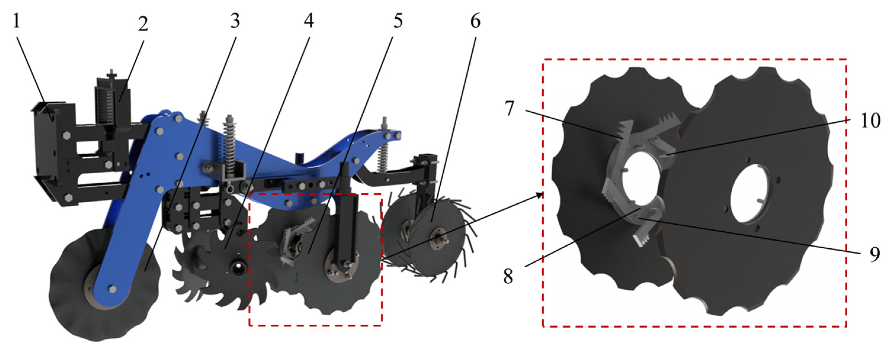
An auxiliary soil-crushing device was integrated into the disc plow system to enhance the soil fragmentation rate and soil disturbance of existing strip-tillage machines (Figure 1) [8]. The strip-till unit consisted of a profiling mechanism, a pressure spring, a straw-cutting coulter, an automatic-width-control row cleaner, two soil-loosening disc plows, and a V-shaped soil-crushing wheel. A good-quality seedbed, free of straw residue and with a uniform soil structure, can be established prior to sowing. The main technical parameters are set out in Table 1.
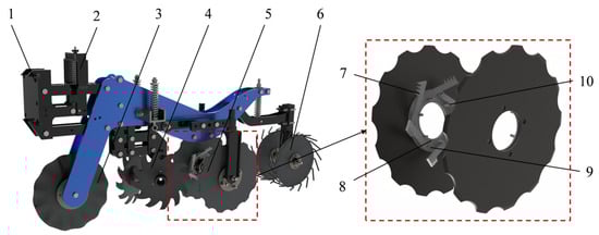
Figure 1.
Schematic of strip-tillage machine and auxiliary soil-crushing device structure. 1. profiling mechanism. 2. tillage-depth-stabilization control system. 3. Straw-cutting coulter. 4. automatic-width-control row cleaner. 5. soil-loosening disc plow. 6. V-shaped soil-crushing wheel. 7. soil-crushing blade. 8. soil-crushing blade disk. 9. soil-crushing blade shaft. 10. positioning lugs.

Table 1.
Main technical parameters.
The auxiliary soil-crushing device comprises two primary components: the soil-crushing blade disk and the soil-crushing blades. The soil-crushing blade shaft was concentrically mounted to the disc at a constant diameter, with positioning lugs welded radially inward. The soil-crushing blades were mounted on the soil-crushing blade shaft, positioned by positioning lugs, and welded to the soil-crushing blade disk after angle adjustment, facilitating precise soil-cutting and fragmentation performance.
During operation, the tractor provides power to drive the implement forward. The pressure spring applies force to the profiling mechanism, maintaining consistent downforce on the monobloc to ensure stable tillage depth. The coulters cut off the residual straw between rows, and the automatic-width row cleaner pushes the residual straws into the working row and throws them to the two sides of the working width. The soil-loosening disc plow loosens and breaks the soil under the preset width in a clean row. Following that, the V-shaped soil-crushing device impacts and breaks the loosened soil, forming clean and consistent strips.
The combined effect of the traction force of the implement and the reaction force of the soil yields a force couple. As a result, the disc plow passively rotates around a fixed axis, exerting compression and overturning forces on the soil within the strip. As the disc plow rotates, the auxiliary soil-crushing device engages with displaced soil particles and the surface soil within the strip, performing cutting and dispersing actions to further fragment the disturbed soil. Subsequently, the crushed soil is redirected by the disc plow, ensuring a level and uniform soil surface within the tilled strip.
2.2. Design and Analysis of Key Components
2.2.1. Design and Analysis of the Soil-Crushing Blade Structure
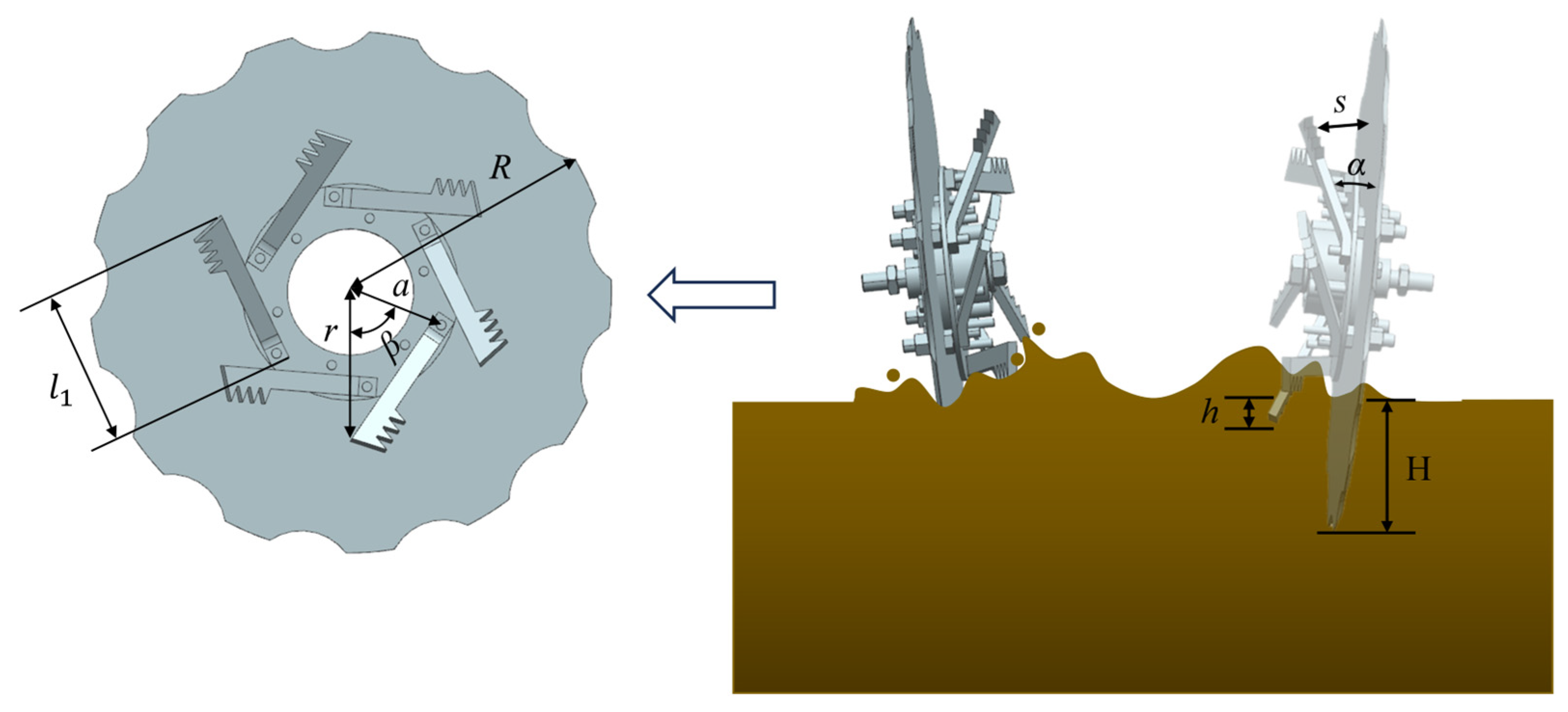
During operation, the working principle of the soil-crushing blade in the auxiliary soil-crushing device is similar to that of a reverse rotary tillage blade [27,28]. In this study, the IT245 rotary tillage curved blade was used as a reference for the design of the soil-crushing blade, with a selected blade rotation angle of 37° [29,30]. Figure 2 illustrates the front view and side view of the soil-crushing blade. As revealed from the analysis, the structural parameters of the soil-crushing blade satisfy:
where denotes the projection length of the soil-crushing blade on the disc plow (m); represents the eccentric distance of the soil-crushing blade (m); indicates the projected rotational radius of the auxiliary soil-crushing device on the disc plow (m); embodies the working width of the soil-crushing blade (m); refers to the rotation angle of the soil-crushing blade (rad); describes the length of the soil-crushing blade (m); expresses the offset angle of the soil-crushing blade (rad).

Figure 2.
Structural parameters of soil-crushing blade.
When the soil-crushing blade reaches its maximum working depth, the following parameters satisfy the given relationship:
where represents the radius of the opposing disc plow (m); denotes the working depth of the opposing disc plow (m); embodies the working depth of the soil-crushing blade (m).
The , , and significantly impact the operational performance of the auxiliary soil-crushing device. In Equations (1)–(4), the working width and the working depth of the soil-crushing blade are the primary structural parameters affecting its operational efficiency.
2.2.2. Determination of Soil-Crushing Blade Parameter Ranges
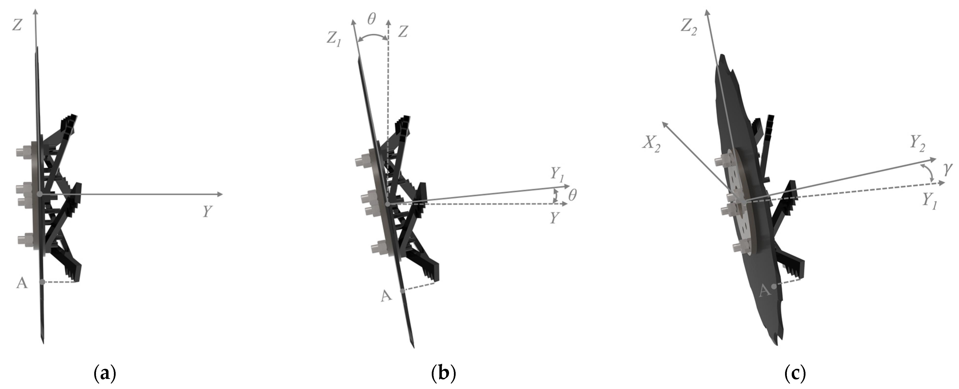
The tilt angle and inclination angle of the disc plow trigger variations in its internal spatial configuration, which directly affect the working width of the soil-crushing blade [14,31,32]. In this study, we established a spatial coordinate system () with the center of the disc plow as the origin to analyze the relationship between blade working width and disc plow rotation angle. Specifically, the X-axis represents the forward direction of the auxiliary soil-crushing device, the Y-axis lies in the horizontal plane perpendicular to the X-axis, and the Z-axis is in the vertical direction. The tip of the soil-crushing blade projects onto the disc plow at point A with coordinates () when the disc plow is not tilted. However, the new coordinates of point A shift to () after the disc plow undergoes tilting and inclination. The maximum Y-axis value of point A was determined through a spatial coordinate rotation matrix and conditional extremum calculations. In this way, the working width range of the soil-crushing blade was optimized to enhance soil fragmentation and simultaneously minimize operational resistance:
where denotes the rotation angle of the opposing disc plow around the forward direction (X-axis) (rad); represents the rotation angle of the opposing disc plow around the vertical direction (Z-axis) (rad); indicates the center distance between the two opposing disc plows (m); embodies the maximum working width of the soil-crushing blade (m) (Figure 3).
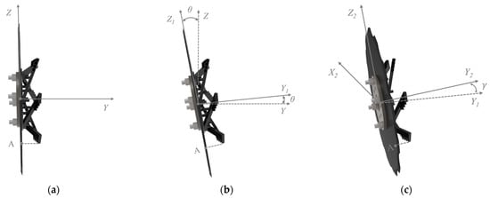
Figure 3.
Schematic of disc plow tilting process. (a) Without tilting or inclination; (b) Tilting around X-axis; (c) Tilting around the Z-axis after the X-axis rotation.
The working width () of the soil-crushing blade is defined as the vertical distance between the blade tip and the disc plow, satisfying the following relationship:
Following the above analysis and the field conditions of low-tillage seeding operations in Northeast China, the tilt angle and inclination angle of the disc plow were set at 5° and 4°, respectively [33]. According to the technical requirements of low-tillage seeding operations, the soil-crushing blade primarily acts on displaced soil clods and compacted surface soil disturbed by the disc plow. Therefore, the penetration depth of the blade tip should be consistent with the seeding depth. It has been calculated based on these design requirements that the parameter ranges for optimal performance are 35 mm ≤ ≤ 95 mm and 30 mm ≤ ≤ 50 mm.
2.2.3. Determination the Number of Soil-Crushing Blades to Be Installed
During operation, the cutting interval of the soil-crushing blade significantly impacts the degree of soil fragmentation [34]. The cutting interval can be calculated by:
where denotes the cutting interval (mm); indicates the forward speed of the implement (m/s); refers to the time interval between two consecutive blade cuts (s); represents the number of blades; stands for the ratio of the blade tip’s circumferential velocity to the implement’s forward velocity; describes the angular velocity of the blade tip’s circular motion.
Finely crushed soil particles can fill voids between each other, forming a stable soil aggregate structure and thus promoting crop growth [35]. As suggested by setting the cutting interval at 60 mm, an optimal blade count of six meets agronomic requirements for effective soil fragmentation [36].
2.3. Bionic Design of Soil-Crushing Blade
In this study, the Oriental mole cricket was selected as the bionic prototype because the strong digging capabilities of its rake-shaped forelegs enable it to be highly effective in soil fragmentation [24,37]. With the purpose of achieving optimal soil-crushing performance, the study primarily focuses on extracting and applying parameters from its more robust claw toes. Specifically, the claw toe length is 1.9 mm, the toe tip angle is 35°, and the distance between adjacent toe tips is 2.5 mm. Regarding practical engineering applications, the rounded shape of the toe tips was simplified in the study by considering only the frontal contour of the claw toes [38]. Based on the earlier analysis of the working width and depth of the soil-crushing blade, the claw toe length and toe tip spacing were scaled proportionally to determine the final structural dimensions of the soil-crushing blade: blade tooth length = 13 mm, tooth spacing = 10 mm, and tooth angle = 35°. The design process is depicted in Figure 4.
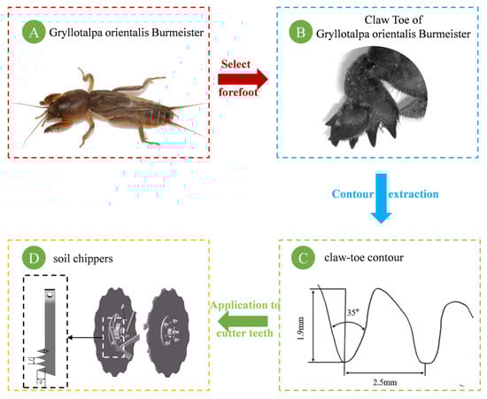
Figure 4.
The bionic design process of the auxiliary soil-crushing blade.
2.4. Simulation Test Based on DEM
2.4.1. Establishment of EDEM Discrete Element Model
The auxiliary soil-crushing device model was simplified by removing irrelevant components that do not affect its operational performance, to ensure rational and effective simulation and computation. The 3D model of the device was created in CATIA P3 V5-6R2020 software (Dassault System, Paris, France) at scale 1:1 and imported into the Geometry module of engineering discrete element method (EDEM) software in .igs format. The material properties of the simulation model were set as follows: 65 Mn steel, a Poisson’s ratio of 0.3, shear modulus of 7.9 × 10¹⁰ Pa, and density of 7865 kg/m3 [39,40]. Considering the structural characteristics of Northeast China’s soil, the Hertz–Mindlin with Bonding model was selected to define the mechanical interactions between soil particles, with a shear modulus of 1.21 × 10⁶ Pa, density of 2130 kg/m3, and Poisson’s ratio of 0.4. Furthermore, a single spherical particle with a radius of 3 mm was adopted as the soil particle model for accurate simulation. The specific contact parameters for the simulation materials are listed in Table 2 [21,41].
Table 2.
Contact parameters of simulation materials.
A virtual soil bin was constructed in EDEM 2021 software (Altair, Troy, MI, USA) to simulate the actual soil-crushing conditions in the field. The dimensions of the soil bin were set to 2200 mm × 500 mm × 300 mm (length × width × height) and designated as a virtual particle factory, ensuring a sufficient quantity of soil particles for simulation (Figure 5). During the generation of soil particles, they could freely settle under gravity. After the formation of the entire particle group, a vertical load was applied on the top layer to calibrate soil density and compact the soil model. This guarantees that the simulation closely matched actual field soil conditions.
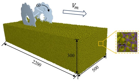
Figure 5.
Soil-crushing operation simulation process.
The simulation process is illustrated in Figure 5.
2.4.2. Simulation Test Measurement Methods
(1) Soil Fragmentation Rate
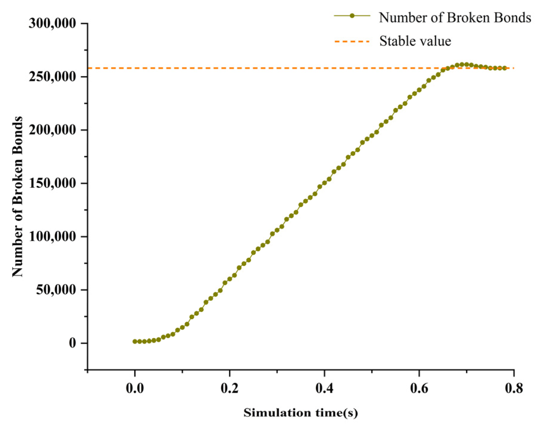
The number of Bonding connections between soil particles was extracted by the Export function in the Analyst module of EDEM software. As shown in Figure 6, the orange dashed indicates the stable value of the number of broken bonds. Afterward, the soil fragmentation rate was determined by calculating the ratio of the number of broken Bonding connections to the total number of Bonding connections within the tilled strip.
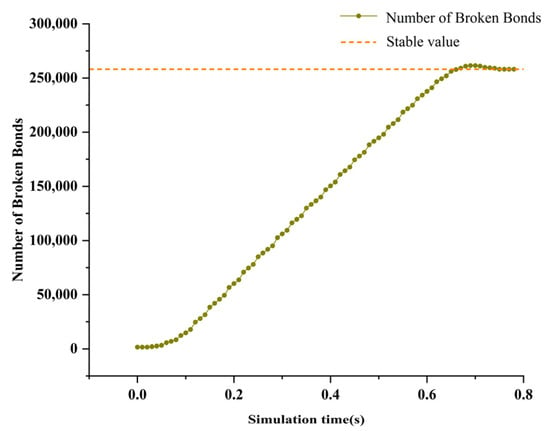
Figure 6.
Number of broken soil particle bonding bonds.
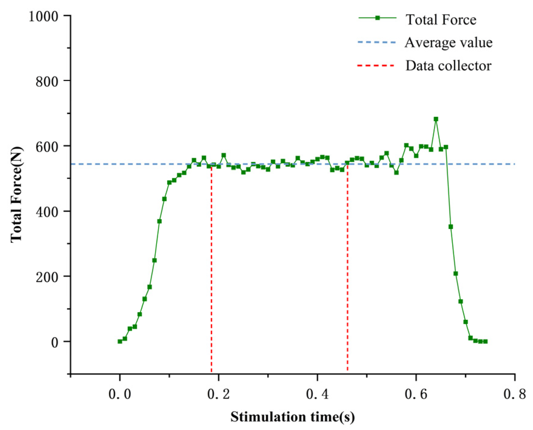
(2) Operational Resistance
The Graph module in the Analyst section of EDEM software was utilized to collect the real-time force data acting on the soil-crushing device during the simulation. The red dashed line in Figure 7 is within the data collection area, and the blue dashed line is the average of the determination of operational resistance in the data collection area as determination of operational resistance.
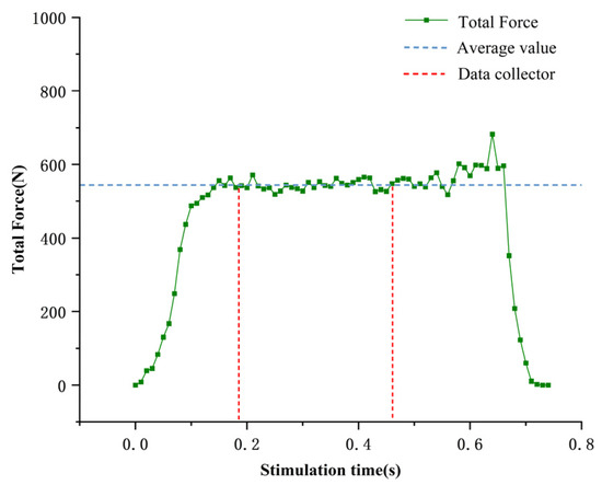
Figure 7.
Determination of operational resistance.
2.4.3. Simulation Test Design
(1) CCD Experiment
The soil-crushing blade parameters were optimized through a two-factor, three-level central composite design (CCD) experiment. Following theoretical analysis, the experimental factors were the blade’s working width and working depth, and the response variables were soil fragmentation rate and operational resistance. The multi-factor experimental variables and their corresponding codes are presented in Table 3.
Table 3.
Experimental factors and levels.
(2) Blade Tooth Structure Comparison Test
The objectives of this test were to investigate the effects of forward speed and different types of blade tooth structures on soil fragmentation rate and operational resistance. While the disc plow parameters and the optimized soil-crushing blade structure remained unchanged, a comparative simulation test was conducted between bionic and non-bionic blade tooth structures at different operating speeds to analyze the effects of bionic design and forward speed on operational performance.
2.5. Field Experiment
2.5.1. Field Experiment Method
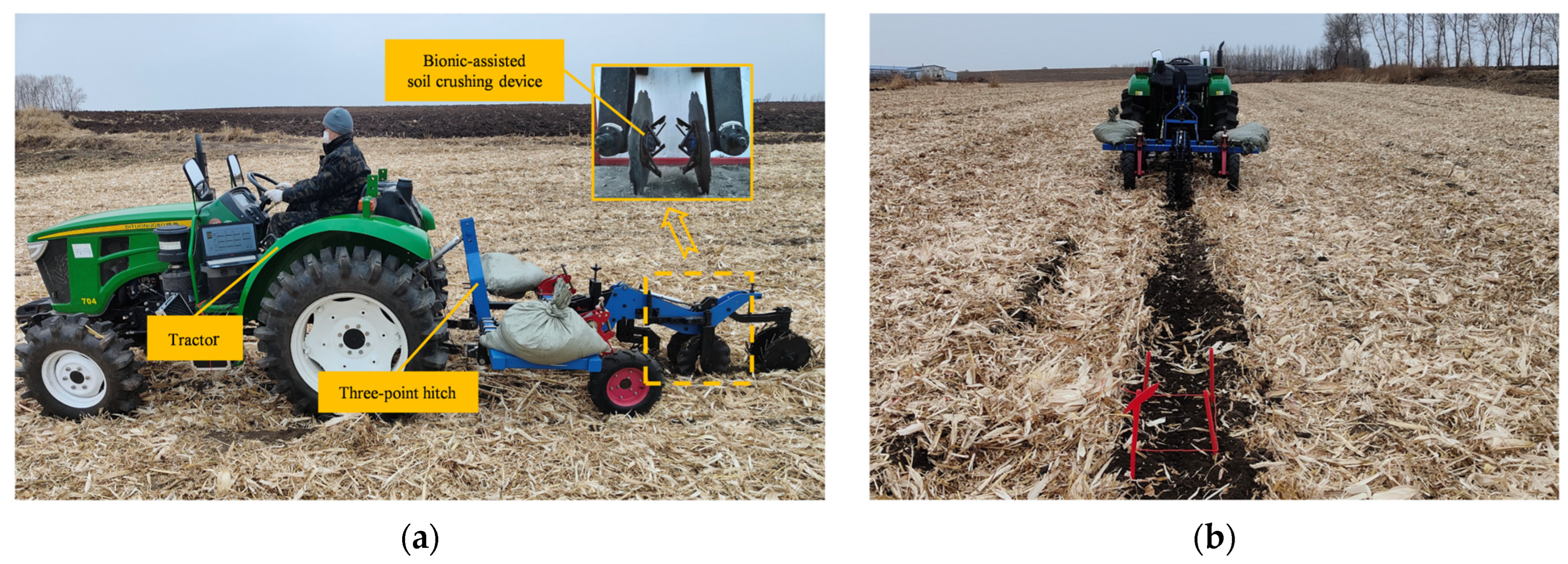
The bionic auxiliary soil-crushing device was designed to reinforce soil fragmentation efficiency. Therefore, our team conducted the field experiment at the Xiangyang Farm Research Base in Harbin, Heilongjiang Province, from 15 to 22 October 2023. Different forward speeds were set in combination with the agronomic standards of Heilongjiang Province to further evaluate the effect of forward speed on soil fragmentation rate. The experimental field featured Northeast black clay soil with maize as the previous crop. The straw cover in the experimental area was quantified as 1.8 kg/m2 using a standardized five-point sampling protocol. The moisture content of the straw was determined to be 50% by oven-drying at 105 °C until constant weight was achieved. This experiment was exclusively designed to assess the soil fragmentation rate without investigating force conditions. The disc plow was attached to a Dituo 704 tractor (Shandong Dituo Agricultural Equipment Co., Ltd., Weifang, China) with a three-point hitch system. To ensure experimental accuracy, we divided each test run into sections, with a working length of 70 m and a working width of 3 m, while designating the middle 50 m as the data collection zone.
During the field experiment, the disc plow working depth was set to 120 mm, and the operating width was set to 260 mm. Besides, the forward speeds of the tractor were set at 6 km/h, 8 km/h, and 10 km/h. The field experiment setup is displayed in Figure 8.
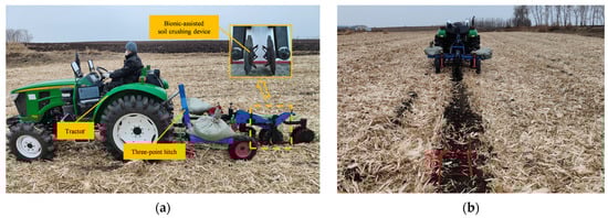
Figure 8.
Field experiment. (a) Field operation of the bionic auxiliary soil-crushing device; (b) Field operation effect.
2.5.2. Bionic Auxiliary Soil-Crushing Device Field Operation
The soil fragmentation performance was evaluated by calculating the percentage of soil clods of different sizes relative to the total soil mass [9]. After each test, soil samples were collected from three evenly spaced measurement points within the data collection zone. Each measurement point had dimensions of 0.5 m (length) × 0.26 m (width) × 0.12 m (height). The mass of soil clods smaller than 4 cm was weighed and compared to the total soil mass in the sample area. Subsequently, the soil fragmentation rate was calculated as the ratio of small clod mass to total soil mass, allowing for a quantitative assessment of the soil-crushing efficiency. The measurement process is provided in Figure 9.
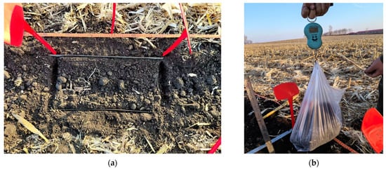
Figure 9.
Operational effect and measurement indicators. (a) Selection of soil fragmentation rate measurement points; (b) Soil fragmentation rate measurement process.
2.6. Statistical Methods
In this study, we conducted parameter optimization, simulation experiments, and field trials using Design-Expert 13 (Stat-Ease, Minneapolis, MN, USA), Excel 2019(Microsoft, Washington, DC, USA), and SPSS 26 software (IBM, Chicago, IL, USA). The collected data were analyzed through least significant difference (LSD) analysis, analysis of variance (ANOVA), regression analysis, and response surface analysis. LSD analysis was performed to evaluate whether significant differences existed between different levels of the same experimental factor. ANOVA and regression analysis were employed to establish the regression equations for the relationship between soil-crushing blade working width, working depth, soil fragmentation rate, and operational resistance. The F-test and p-value were applied to select the most suitable model. Additionally, the response surface analysis was performed to visualize the interaction effects of soil-crushing blade parameters on the response indicators. LSD analyses and Tukey’s test were used to assess whether there were significant differences between different levels of cutter tooth type and forward speed. This was used to determine whether the bionic knife teeth had a significant advantage in terms of work resistance and soil fragmentation rate, and to identify the pattern of the effect of different levels of operating speed on these two indicators. Furthermore, the LSD analysis was implemented to investigate whether significant differences existed between the field test results of machines with and without the bionic auxiliary soil-crushing device.
3. Results and Discussion
3.1. Optimization and Analysis of CCD Experiment
The experimental results are presented in Table 4.
Table 4.
Experimental design and results.
3.1.1. ANOVA
A multiple regression fitting was performed on the data in Table 4, to establish regression equations for soil fragmentation rate and operational resistance as functions of working width and working depth , expressed as:
The ANOVA for the response values and is summarized in Table 5. The lack-of-fit terms for both models were greater than 0.05, implying that the lack of fit was insignificant. In other words, the regression models fit well. The p-values for the regression models were both less than 0.01, reflecting that they are highly significant and that the regression results are reliable.
Table 5.
ANOVA results.
The analysis of soil fragmentation rate reveals that , , and have a highly significant impact (p < 0.01); has a significant impact (0.01 < p < 0.05); and the interaction terms x1 and x2 do not exhibit a significant impact. The factor weight ranking for soil fragmentation rate is: working depth > working width, suggesting that working depth exerts a greater impact on soil fragmentation compared to working width. Similarly, the analysis of operational resistance demonstrates that and have a highly significant impact (p < 0.01), and the interaction terms and have a significant impact (0.01 < p < 0.05), but and do not have a significant impact. The factor weight ranking for operational resistance is: working width > working depth.
3.1.2. Response Surface Analysis
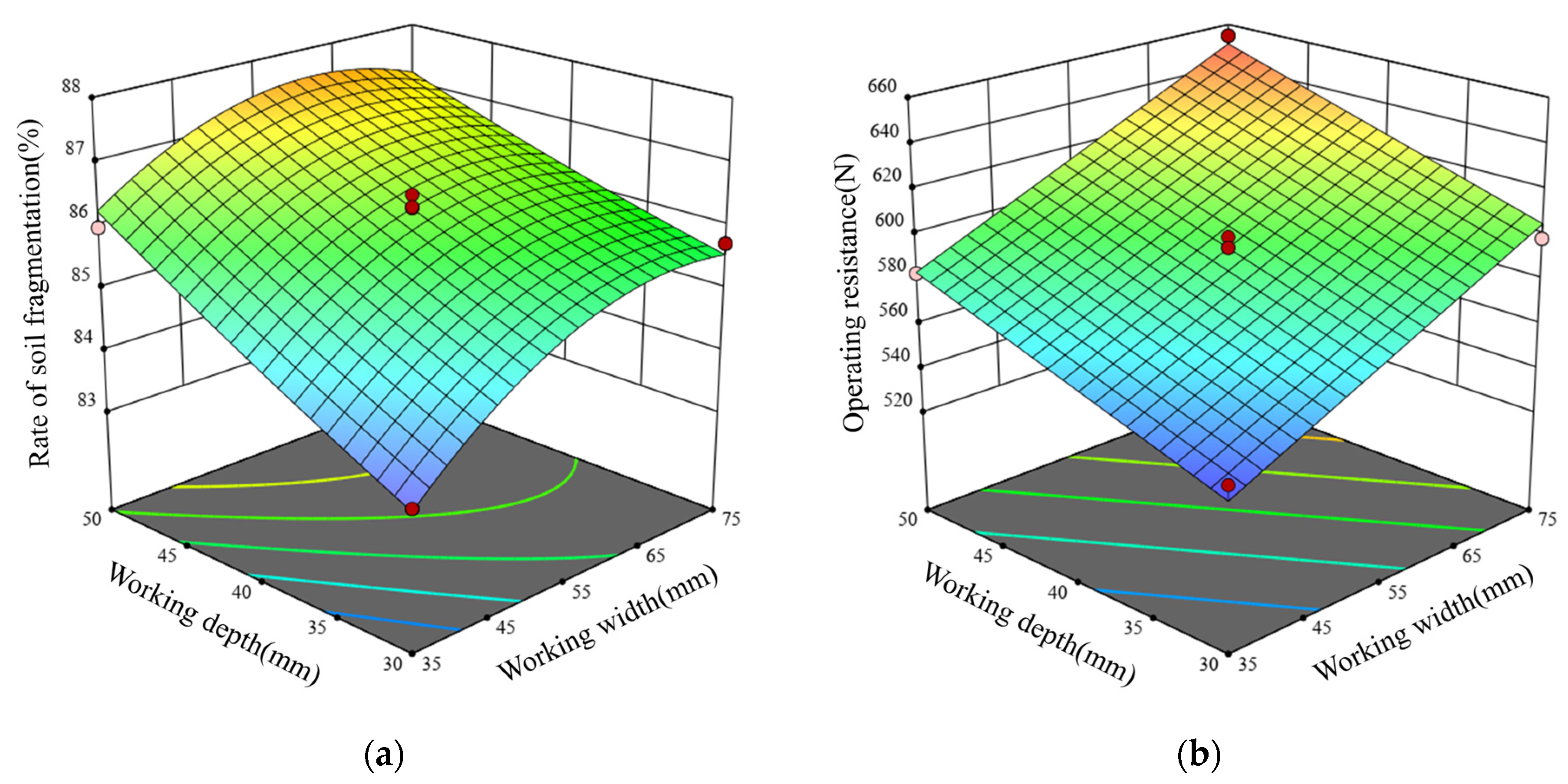
Figure 10a illustrates the effect of the working width and working depth of the soil-crushing blade on the soil fragmentation rate. When the working depth remains constant, the soil fragmentation rate initially increases and then decreases with the working width. When the working width remains constant, the soil fragmentation rate increases as the working depth increases. The primary reason for this trend is that as working width increases, maintaining the same working depth necessitates a longer blade, contributing to greater soil penetration, an expanded working range, and thereby reinforced soil fragmentation. However, the angle between the soil-crushing blade and the disc plow also increases when the working width continues to increase, potentially triggering soil accumulation. This accumulation can obstruct the interaction between soil particles and the disc plow, lowering the degree of soil fragmentation. In contrast, increasing the working depth results in the blade engaging with a larger volume of soil particles, and, hence, fragmentation efficiency is enhanced through additional effects and cutting actions.
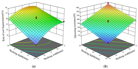
Figure 10.
Interaction effects on experimental indicators. (a) Interaction effect on soil fragmentation rate; (b) Interaction effect on operational resistance.
Figure 10b illustrates the effect of working width and working depth on operational resistance. When the working depth remains constant, operational resistance increases as the working width increases. When the working width remains constant, operational resistance also increases with increasing working depth. This trend can be explained as follows: a wider working width enlarges the cutting area, requiring the blade to break and displace more soil. As a result, operational resistance is strengthened. Similarly, a greater working depth brings about deeper soil penetration, an expanded contact area between the blade and soil particles, and subsequently higher operational resistance. This finding aligns with the research conducted by Hasimu [42], which suggests that operational resistance increases with the depth of operation and width of operation of the implement.
An optimization design was conducted based on the principles of maximizing soil fragmentation rate and minimizing operational resistance to determine the optimal structural parameter combination for the soil-crushing blade. A multi-objective variable optimization method was employed under the integration with the boundary conditions of the experimental factors. A nonlinear programming parameter model was established as:
We analyzed and solved the mathematical model through the optimization module in Design-Expert 13 software to determine the optimal parameter combination. A reasonable set of structural parameters was selected based on the optimization results. Specifically, when the working width of the soil-crushing blade was 40.66 mm and the working depth was 50 mm, the operational performance was ideal, with a soil fragmentation rate of 86.74% and an operational resistance of 590.81 N. Furthermore, we performed a virtual simulation using the optimized parameters to validate these results. The simulation yielded a soil fragmentation rate of 86.90% and an operational resistance of 589.43 N, consistent with the optimization results. Thus, it was confirmed that the model possesses favorable accuracy and reliability of predictions.
3.2. Blade Tooth Structure Comparison Test
The comparative test results of different blade tooth structures are shown in Table 6.
Table 6.
Comparison of test results with different types of blade tooth structure.
In Figure 11, the type of blade tooth structure exerted a highly significant impact on operational resistance (p < 0.01). The bionic blade tooth structure (Bs) exhibited an average operational resistance of 604.68 N, which was 7.682% lower than that of the original blade tooth structure (Os). This finding aligns with the research conducted by Jia [43], which suggests that the special sawtooth shape cuts more effectively and requires less force to complete the job than the original saw blade. Further analysis also unveils that operating speed posed a highly significant impact on operational resistance (p < 0.01). As the forward speed increased from 6 km/h to 10 km/h, the average operational resistance rose from 613.61 N to 643.44 N, a 4.86% increase. This can be attributed to the fact that a higher forward speed resulted in a higher rotational speed of the soil-crushing blade, an increased amount of soil engaged per unit time, a greater force required to overcome soil shear strength, and thus higher operational resistance—similar to the findings of Kheiralla [44].
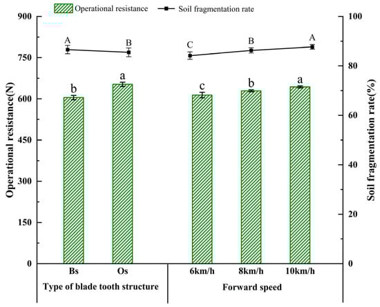
Figure 11.
Effects of different blade tooth structures and forward speed on experimental indicators: means followed by different lowercase or uppercase letters are significantly different according to Tukey’s test and LSD multiple range test at the significance level of 0.05; error bars are standard deviations.
Figure 11 exhibits the variation in soil fragmentation rate as a function of blade tooth structure and forward speed. The Bs demonstrated a higher average soil fragmentation rate of 86.59%, which was 1.45% higher than that of the Os. This finding aligns with the research conducted by Zhu [37], where a soil-crushing blade with bionic tooth profiles improved crushing performance compared to conventional blades. Further analysis specifies that the soil fragmentation rate increased with increasing forward speed. When the forward speed increased from 6 km/h to 10 km/h, the average soil fragmentation rate rose from 84.15% to 87.70%, a 4.22% improvement. This can be explained by the fact that higher forward speeds contributed to a higher blade rotational speed, which in turn increased the number of effects per unit time and therefore reinforced soil fragmentation efficiency—similar to the findings of Matin [45].
3.3. Field Experiment Results
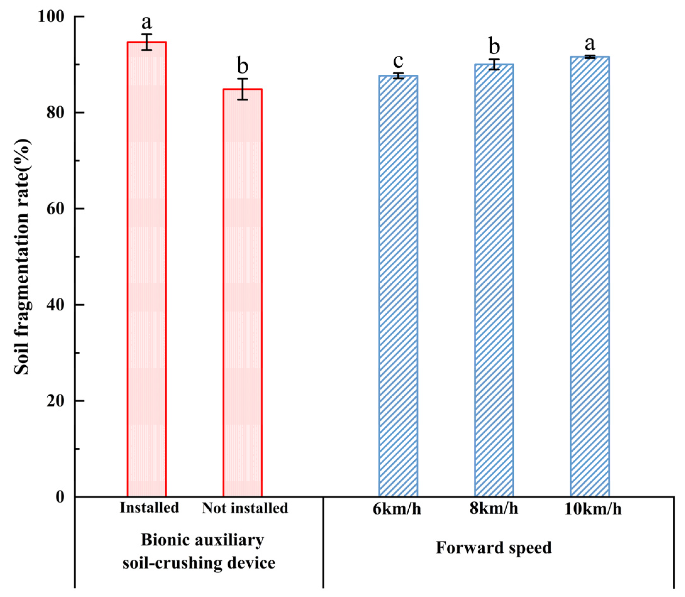
In Figure 12, the presence of the bionic auxiliary soil-crushing device exerted a highly significant impact on the soil fragmentation rate (p < 0.01). When the bionic auxiliary soil-crushing device was installed, the average soil fragmentation rate reached 94.54%, which was 11.54% higher than that obtained when the device was not installed. This improvement was achieved due to the ability of the bionic auxiliary soil-crushing device to effectively crush displaced soil clods and compacted surface soil disrupted by the disc plow, thereby enhancing the overall soil fragmentation rate. Additionally, operating speed also posed a highly significant impact on the soil fragmentation rate (p < 0.01). An increase in the forward speed from 6 km/h to 10 km/h led to a growth of the average soil fragmentation rate from 87.67% to 91.60%, a 4.48% improvement.
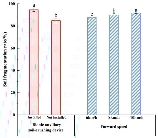
Figure 12.
Field experiment results: means followed by different lower case letters are significantly different according to Tukey’s test and LSD multiple range test at the significance level of 0.05; error bars are standard deviations.
Although certain discrepancies appeared between the field experiment results and the simulation results, their trends remained consistent. The measured soil fragmentation rate in the simulation was lower than that in the field experiment owing to differences in data collection methods. The field experiment excluded soil clods smaller than 4 cm, whereas soil aggregates under 4 cm may still have contained unbroken bonding connections in the simulation, leading to an underestimation of the fragmentation rate in the simulation.
4. Conclusions
In this study, we designed and analyzed a bionic auxiliary soil-crushing device. Specifically, the optimal parameter range was determined by theoretical analysis, and biomimetic tooth structures were designed following the claw-toe morphology of the Oriental mole cricket. Additionally, we optimized the structural parameters of the soil-crushing blade and compared the performance of different blade tooth structures by employing a discrete element simulation model. The device was further validated through field experiments. The main conclusions are outlined as follows.
Theoretical analysis and numerical calculations established that the working width (s) and working depth (h) of the soil-crushing blade were the key structural parameters affecting operational performance. The optimal parameter range was determined as 35 mm ≤ s ≤ 95 mm and 30 mm ≤ h ≤ 50 mm. Based on the claw-toe contour of the Oriental mole cricket, a bionic design was developed for the soil-crushing blade teeth.
We constructed a discrete element simulation model suitable for Northeast China’s soil conditions. A CCD experiment was conducted with working width and working depth as experimental factors and soil fragmentation rate and operational resistance as response variables. Furthermore, we established a mathematical model to analyze the relationship between factors and response indicators and adopted a multi-objective optimization model to determine the optimal parameter combination: working width = 40.66 mm and working depth = 50 mm. A comparative simulation of two blade tooth structures suggested that the bionic blade tooth structure significantly improved operational performance, with a soil fragmentation rate of 86.90% and an operational resistance of 589.43 N. These results demonstrated a 1.45% increase in soil fragmentation rate and a 7.68% reduction in operational resistance compared to the original blade tooth structure.
Field experiments were performed on the simulation results. The results revealed that after the bionic auxiliary soil-crushing device was installed, the soil fragmentation rate reached 94.54%, an 11.54% increase compared to the non-installed condition. The trends in the field test results were consistent with the simulation results, verifying the reliability of the design. Moreover, the superior operational performance of the machine with the bionic auxiliary soil-crushing device satisfied the agronomic and technical requirements for strip-tillage operations.
This study has several limitations. The test results were obtained in a defined plot, so the machine may need to be made adjustable when used in other plots. Additionally, we did not consider energy consumption when measuring resistance. In future research, we will conduct a farm-scale experiment and assess the energy consumption of the tillage process under different operating modes.
Author Contributions
Conceptualization, Q.W.; methodology, Y.Z. and Q.W.; software, Y.Z., K.Z., and Y.-Y.Z.; validation, K.Z., Y.-Y.Z. and X.Z.; formal analysis, Y.Z. and X.Z.; investigation, Y.Z. and Q.W.; resources, Q.W.; data curation, Y.Z. and X.Z.; writing—original draft preparation, K.Z., Y.-Y.Z., and Q.W.; writing—review and editing, Q.W. and X.F.; visualization, Q.W.; supervision, Q.W. and X.F.; project administration, Q.W. and J.W.; funding acquisition, Q.W. and J.W. All authors have read and agreed to the published version of the manuscript.
Funding
This research was financially supported by the Heilongjiang Provincial Key Research and Development Program (No. 2022ZX05B04), the National Natural Science Foundation of China (No. 52005094, No. 52205253), the Heilongjiang Provincial Natural Science Foundation of China (No. LH2022E007), and the Heilongjiang Provincial Natural Science Foundation Research Team Project (No. TD2023E001).
Institutional Review Board Statement
Not applicable.
Data Availability Statement
The original contributions presented in this study are included in the article. Further inquiries can be directed to the corresponding authors.
Acknowledgments
The authors would like to thank their schools and colleges, as well as the funding providers of the project. All support and assistance are sincerely appreciated.
Conflicts of Interest
The authors declare no conflicts of interest.
References
- Blanco-Canqui, H.; Lal, R. Crop residue removal impacts on soil productivity and environmental quality. Crit. Rev. Plant Sci. 2009, 28, 139–163. [Google Scholar] [CrossRef]
- Ren, Z.J.; Han, X.J.; Feng, H.X.; Wang, L.F.; Ma, G.; Li, J.H.; Lv, J.J.; Tian, W.Z.; He, X.H.; Zhao, Y.N.; et al. Long-term conservation tillage improves soil stoichiometry balance and crop productivity based on a 17-year experiment in a semi-arid area of northern china. Sci. Total Environ. 2024, 908, 168283. [Google Scholar] [CrossRef] [PubMed]
- Nunes, M.R.; Karlen, D.L.; Veum, K.S.; Moorman, T.B.; Cambardella, C.A. Biological soil health indicators respond to tillage intensity: A us meta-analysis. Geoderma 2020, 369, 114335. [Google Scholar] [CrossRef]
- Xu, X.Z.; Xu, Y.; Chen, S.C.; Xu, S.G.; Zhang, H.W. Soil loss and conservation in the black soil region of northeast china: A retrospective study. Environ. Sci. Policy 2010, 13, 793–800. [Google Scholar] [CrossRef]
- Tagar, A.A.; Adamowski, J.; Memon, M.S.; Do, M.C.; Mashori, A.S.; Soomro, A.S.; Bhayo, W.A. Soil fragmentation and aggregate stability as affected by conventional tillage implements and relations with fractal dimensions. Soil. Till Res. 2020, 197, 104494. [Google Scholar] [CrossRef]
- Guan, C.S.; Fu, J.J.; Xu, L.; Jiang, X.Z.; Wang, S.L.; Cui, Z.C. Study on the reduction of soil adhesion and tillage force of bionic cutter teeth in secondary soil crushing. Biosyst. Eng. 2022, 213, 133–147. [Google Scholar] [CrossRef]
- Wang, J.W.; Wen, N.; Liu, Z.M.; Zhou, W.Q.; Tang, H.; Wang, Q.; Wang, J.F. Coupled bionic design of liquid fertilizer deep application type opener based on sturgeon streamline to enhance opening performance in cold soils of northeast China. Agriculture 2022, 12, 615. [Google Scholar] [CrossRef]
- Wang, Q.; Wang, B.; Sun, M.J.; Sun, X.B.; Zhou, W.Q.; Tang, H.; Wang, J.W. Design and testing of an automatic strip-till machine for conservation tillage of corn. Agronomy 2023, 13, 2357. [Google Scholar] [CrossRef]
- Wu, B.; Huang, T.C.; Qiu, X.X.; Zuo, T.L.; Wang, X.S.; Xie, F.P. Design and experimental study of potato-soil separation device for sticky soils condition. Appl. Sci. 2021, 11, 10959. [Google Scholar] [CrossRef]
- Tukhtakuziyev, A.; Ishmuradov, S.U.; Abdumajidov, R. Researching the parameters of the disc plough and its smooth run throughout the tillage depth. In IOP Conference Series: Earth and Environmental Science; IOP Publishing: Bristol, UK, 2021; p. 012058. [Google Scholar]
- Han, C.J.; Liu, Z.; Mao, H.P.; Ma, X.; Wang, S. Design and experiment of variable rate fertilization combined soil preparation machine. Trans. Chin. Soc. Agric. Mach. 2024, 55, 250–261, 284. [Google Scholar]
- Li, F.; Yang, H.J.; Zheng, X.; Hu, H.Y. Development of the soil layer construction device for the cotton seedbed in sandy soil of arid areas. Trans. Chin. Soc. Agric. Eng. (Trans. CSAE) 2024, 40, 55–65. [Google Scholar]
- Kayombo, B.; Lal, R. Effects of soil compaction by rolling on soil structure and development of maize in no-till and disc ploughing systems on a tropical alfisol. Soil. Tillage Res. 1986, 7, 117–134. [Google Scholar] [CrossRef]
- Ucgul, M. Simulating soil–disc plough interaction using discrete element method–multi-body dynamic coupling. Agriculture 2023, 13, 305. [Google Scholar] [CrossRef]
- Onwualu, A.; Watts, K. Draught and vertical forces obtained from dynamic soil cutting by plane tillage tools. Soil. Tillage Res. 1998, 48, 239–253. [Google Scholar] [CrossRef]
- Zhong, G.Y.; Li, H.W.; He, J.; Wang, Q.J.; Lu, C.Y.; Wang, C.; Tong, Z.W.; Cui, D.D.; He, D. Design and test of single-disc opener for no-till planter based on support cutting. Agriculture 2023, 13, 1635. [Google Scholar] [CrossRef]
- Zeng, Z.W.; Chen, Y. Performance evaluation of fluted coulters and rippled discs for vertical tillage. Soil. Till Res. 2018, 183, 93–99. [Google Scholar] [CrossRef]
- Li, J.W.; Li, X.Y.; Hu, B.; Gu, T.L.; Wang, Z.J.; Wang, H.L. Analysis of the resistance reduction mechanism of potato bionic digging shovels in clay and heavy soil conditions. Comput. Electron. Agr. 2023, 214, 108315. [Google Scholar] [CrossRef]
- Jia, H.L.; Wang, W.J.; Wang, W.P.; Zheng, J.; Wang, Q.; Zhuang, J. Application of anti-adhesion structure based on earthworm motion characteristics. Soil. Till Res. 2018, 178, 159–166. [Google Scholar] [CrossRef]
- Sun, J.Y.; Wang, Y.M.; Ma, Y.H.; Tong, J.; Zhang, Z.J. Dem simulation of bionic subsoilers (tillage depth >40 cm) with drag reduction and lower soil disturbance characteristics. Adv. Eng. Softw. 2018, 119, 30–37. [Google Scholar] [CrossRef]
- Wang, Q.; Wang, Z.M.; Zhang, Z.H.; Zhang, K.; Yao, S.; Zhou, W.Q.; Sun, X.B.; Wang, J.W. Design and test of bionic elastic row cleaner with improved straw cleaning performance. Agriculture 2024, 14, 186. [Google Scholar] [CrossRef]
- Zhao, J.L.; Lu, Y.; Wang, X.G.; Zhuang, J.; Han, Z.W. A bionic profiling-energy storage device based on mbd-dem coupled simulation optimization reducing the energy consumption of deep loosening. Soil. Till Res. 2023, 234, 105824. [Google Scholar] [CrossRef]
- Tan, H.C.; Shen, C.C.; Ma, J.L.; Wu, C.L.; Xu, L.M.; Ma, S. The reduction of energy consumption and soil disturbance mechanisms in trenching using biomimetic blades. Comput. Electron. Agr. 2025, 230, 109887. [Google Scholar] [CrossRef]
- Zhang, Z.J.; Jia, H.L.; Sun, J.Y. Review of application of biomimetics for designing soil-engaging tillage implements in northeast china. Int. J. Agric. Biol. Eng. 2016, 9, 12–21. [Google Scholar]
- Xiao, M.; Wang, K.; Yang, W.; Wang, W.; Jinag, F. Design and experiment of bionic rotary blade based on claw toe of Gryllotalpa orientalis burmeister. Nongye Jixie Xuebao/Trans. Chin. Soc. Agric. Mach. 2021, 52, 55–63. [Google Scholar]
- Liu, S.H.; Weng, S.J.; Liao, Y.L.; Zhu, D.Y. Structural bionic design for digging shovel of cassava harvester considering soil mechanics. Appl. Bionics Biomech. 2014, 11, 1–11. [Google Scholar] [CrossRef]
- Shibusawa, S. Reverse-rotational rotary tiller for reduced power requirement in deep tillage. J. Terramechanics 1993, 30, 205–217. [Google Scholar] [CrossRef]
- Salokhe, V.; Ramalingam, N. Effects of direction of rotation of a rotary tiller on properties of bangkok clay soil. Soil. Tillage Res. 2001, 63, 65–74. [Google Scholar] [CrossRef]
- Wang, J.; Yang, D.; Wang, Z.; Fu, Z.; Wang, J.; Weng, W. Design and experiment of rice straw biaxial deep-buried returning machine. Nongye Jixie Xuebao/Trans. Chin. Soc. Agric. Mach. 2023, 54, 21–30. [Google Scholar]
- Zhang, X.Y.; Yu, S.Y.; Hu, X.; Zhang, L.X. Study on rotary tillage cutting simulations and energy consumption predictions of sandy ground soil in a xinjiang cotton field. Comput. Electron. Agr. 2024, 217, 108646. [Google Scholar] [CrossRef]
- O’Dogherty, M.; Godwin, R.; Hann, M.; Al-Ghazal, A. A geometrical analysis of inclined and tilted spherical plough discs. J. Agric. Eng. Res. 1996, 63, 205–217. [Google Scholar] [CrossRef]
- Kogut, Z.; Sergiel, L.; Żurek, G. The effect of the disc setup angles and working depth on disc harrow working resistance. Biosyst. Eng. 2016, 151, 328–337. [Google Scholar] [CrossRef]
- Cheng, Y.; Yan, X.; Zhu, R.; Li, C.; Liu, Y.; Liu, Z.; Lu, Q. Design and experiment of testing device for passive disc. J. Northwest Univ. Nat. Sci. Ed. 2016, 44, 228–234. [Google Scholar]
- Yang, Z.; Zhang, K.; Zhang, Y.; An, J. Discrete element method–multibody dynamics coupling simulation and experiment of rotary tillage and ridging process for chili pepper cultivation. Agronomy 2024, 14, 446. [Google Scholar] [CrossRef]
- Tisdall, J.M.; Oades, J.M. Organic matter and water-stable aggregates in soils. J. Soil Sci. 1982, 33, 141–163. [Google Scholar] [CrossRef]
- Bao, P.; Wu, M.; Guan, C.; Luo, H.; He, Y.; Xiang, W. Design of plow-rotary style ditching and ridging device for rapeseed seeding. Trans. Chin. Soc. Agric. Eng. 2017, 33, 23–31. [Google Scholar]
- Zhu, H.; Wang, D.; He, X.; Shang, S.; Zhao, Z.; Wang, H.; Tan, Y.; Shi, Y. Study on plant crushing and soil throwing performance of bionic rotary blades in cyperus esculentus harvesting. Machines 2022, 10, 562. [Google Scholar] [CrossRef]
- Zhang, Z.; Sun, X.; Jin, Z.; Bing, Z.; Sun, J.; Tong, J. Design and test of crushing bionic soil covering device of soybean seeder. Nongye Jixie Xuebao/Trans. Chin. Soc. Agric. Mach. 2018, 49, 34–40. [Google Scholar]
- Zhu, A.W.; Xu, C.T.; Liu, Y.F.; Wang, J.S.; Tan, X.D. Design and experiment of oblique stubble-cutting side-throwing anti-blocking device for no-tillage seeder. Agriculture 2024, 14, 2250. [Google Scholar] [CrossRef]
- Zhang, L.; Wang, X.W.; Chen, J.N.; Wang, H.Y.; Cao, Y.G. Analysis and optimization of low-resistance animal bionic subsoiling shovel based on edem. Agriculture 2024, 14, 2046. [Google Scholar] [CrossRef]
- Zhao, S.; Gao, L.; Yuan, Y.; Hou, L.; Zhang, X.; Yang, Y. Maize straw motion law in subsoiling operation using discrete element method. Trans. Chin. Soc. Agric. Eng. 2021, 37, 53–62. [Google Scholar]
- Hasimu, A.; Chen, Y. Soil disturbance and draft force of selected seed openers. Soil. Till Res. 2014, 140, 48–54. [Google Scholar] [CrossRef]
- Jia, H.L.; Li, C.Y.; Zhang, Z.H.; Wang, G. Design of bionic saw blade for corn stalk cutting. J. Bionic Eng. 2013, 10, 497–505. [Google Scholar] [CrossRef]
- Kheiralla, A.F.; Yahya, A.; Zohadie, M.; Ishak, W. Modelling of power and energy requirements for tillage implements operating in serdang sandy clay loam, malaysia. Soil. Till Res. 2004, 78, 21–34. [Google Scholar] [CrossRef]
- Matin, M.A.; Fielke, J.M.; Desbiolles, J.M.A. Torque and energy characteristics for strip-tillage cultivation when cutting furrows using three designs of rotary blade. Biosyst. Eng. 2015, 129, 329–340. [Google Scholar] [CrossRef]


Disclaimer/Publisher’s Note: The statements, opinions and data contained in all publications are solely those of the individual author(s) and contributor(s) and not of MDPI and/or the editor(s). MDPI and/or the editor(s) disclaim responsibility for any injury to people or property resulting from any ideas, methods, instructions or products referred to in the content. |
© 2025 by the authors. Licensee MDPI, Basel, Switzerland. This article is an open access article distributed under the terms and conditions of the Creative Commons Attribution (CC BY) license (https://creativecommons.org/licenses/by/4.0/).