Article

Alignment Error Modelling, Analysis and Experiment of the Deep-Water Bolt Flange Automatic Connection Tool

College of Mechanical and Electrical Engineering, Harbin Engineering University, Harbin 150001, China
*
Author to whom correspondence should be addressed.
J. Mar. Sci. Eng. 2022, 10(1), 64; https://doi.org/10.3390/jmse10010064
Submission received: 19 December 2021 / Revised: 29 December 2021 / Accepted: 30 December 2021 / Published: 5 January 2022
(This article belongs to the Special Issue Frontiers in Deep-Sea Equipment and Technology)

Abstract

:
A deep-water bolt flange automatic connection tool plays a very important role in the process of offshore oil exploitation and transportation. In the connection process, the alignment error of bolts and nuts is the key factor to ensure the connection process is successful. Using the kinematics modeling method, this paper created the alignment error model of the deep-water bolt flange automatic connection tool and analyzed the influence of manufacturing accuracy on the alignment error of bolts and nuts through computer simulation software. Based on the error matching design method, the manufacturing accuracy of parts were optimized with a part-size-based priority sequence to ensure the bolt–nut alignment error was within the allowable limits. The land tests, the pool tests and the sea test were carried out. The test results showed that the bolt and nut can be connected in the subsea environment reliably.

1. Introduction

In the process of offshore oil exploitation and transportation, the submarine oil pipeline plays an important role in regard of safety, reliability and economy [1,2,3]. Bolt flange connection is the main connection method of a submarine pipeline [4,5,6]. Thus far, companies, such as the United States Sonsub, Norway Acergy and Switzerland All Seas Group, have used a deep-water bolt flange automatic connection tool in the process of pipeline connection [7,8]. In the connection process of the deep-water bolt flange automatic connection tool, the critical function is to lead the bolts into nuts at the same time and the alignment error of the bolts and nuts is the key factor.
In recent years, the error control method has been studied. Jia Z [9] presented a comprehensive review of the state of the art of the contouring-error reduction methods, the studies on constraining the contouring errors were classified and summarized, and, accordingly, the advantages and the disadvantages of different kinds of methods were discussed and compared. To meet the tolerance requirements of parts, Zhang J [10] proposed a high-accuracy estimation method of a contouring error that was not related to (without) a datum (ND-contouring error), and the results showed that the contouring error could be significantly reduced to improve the quality of the parts. Yang X [11] presented a novel computationally efficient contouring error estimation method for contouring control; the experimental result showed that the proposed method eliminated the sudden change of the contouring error vector directions in large curvature regions. Yang J [12] proposed a novel control structure that treated the form error as a direct objective. Experimental results showed that the proposed form error estimation and compensation methodology significantly improves the contouring accuracy. Liu Z [13] proposed an algorithm to calculate the exact contouring error of the NURBS tool path in real time; experiments were conducted, the experimental results showed the effectiveness of the proposed algorithm, and the actual contouring error was reduced significantly compared with the other methods. Zhang D [14] proposed a variable-parameter-model-based iterative pre-compensation method of the tracking error; experiments were conducted, and the results showed that the variable-parameter-model-based iterative pre-compensation method of the tracking error could reduce the tracking error and adapt to the change of the moment-of-inertia.
However, due to a technical blockade, few studies about the deep-water bolt flange automatic connection tool can be found, particularly the alignment error and tolerance assignment. It is necessary to study the deep-water bolt flange automatic connection tool to improve the performance of the deep-water bolt flange automatic connection tool. This study created the alignment error model of the deep-water bolt flange automatic connection tool using the kinematics modeling method in Section 2. The alignment error of the bolt and nut were calculated with simulation software, and the influence of the manufacturing accuracy/tolerance of each part on the alignment error was analyzed in Section 3. Based on the error matching design method, the manufacturing accuracy of parts was optimized with the part-size-based priority sequence in Section 4. The land tests, pool tests and sea test were carried out in Section 5. The test results showed that the bolt and nut can be connected successfully with the optimized tolerance assignment, which showed the design of the deep-water bolt flange automatic connection tool can be used in a subsea environment reliably.

2. Error Model of Deep-Water Bolt Flange Automatic Connection Tool

The structure of the deep-water bolt flange automatic connection tool is as shown in Figure 1. The frame mainly plays a role of support. The structures of the bolt magazine and the nut magazine are as shown in Figure 2 and Figure 3, respectively. The overall structure is a three-petal type; the two lower petals can be opened and closed by hydraulic cylinders, and they move axially along the linear guide or rotate circumferentially along the ring guide; the bolts are held in the bolt magazine through the locking mechanism and can be released after the connection is completed; the nuts are located in the nut sleeve, and their position and angle can be adjusted. The tensioner in the tensioner magazine stretches the bolt after the bolts are led into the nuts, to ensure enough preload, and the claw holds the flange in the right position.
In order to analyze the error of the deep-water bolt flange automatic connection tool, the coordinate system is defined using the Denavit–Hartenberg method (D–H method) [15]. The D–H method uses four parameters, αi, θi, ai and di, to describe the relative position of two adjacent coordinate systems.
The coordinate system of the deep-water bolt flange automatic connection tool is created using the D–H method, as shown in Figure 4. The initial coordinate system O0X0Y0Z0 is established on the frame, the coordinate system of the bolt magazine is OiXiYiZi (i = 1~5), and that of nut magazine is OiXiYiZi (i = 1~5).
The torsion angle αi is the angle of the Zi−1 axis and Zi axis about the Xi axis; the joint angle θi is the angle of the Xi−1 axis and Xi axis about the Zi−1 axis, the length ai is the distance between the Zi−1 axis and Zi axis along the Xi axis, and the offset di is the distance from the origin Oi−1 of the i−1 coordinate system to the Xi axis along the Zi−1 axis. According to the D–H method, the general transformation formula is as follows:
T i i 1 = [ cos θ i sin θ i 0 a i cos α i sin θ i cos α i cos θ i sin α i d i sin α i sin α i sin θ i sin α i cos θ i cos α i d i cos α i 0 0 0 1 ] .
The D–H parameters for error modelling and analysis are listed in Table 1.
The transformation matrix of the bolt tip (away from the bolt magazine) relative to the initial coordinate system O0X0Y0Z0 is,
T 5 0 = T 1 0 T 2 1 T 3 2 T 4 3 T 5 4 = [ N x 5 O x 5 A x 5 P x 5 N y 5 O y 5 A y 5 P y 5 N z 5 O z 5 A z 5 P z 5 0 0 0 1 ] .
The transformation matrix of the bolt cap (in the bolt magazine) relative to the initial coordinate system O0X0Y0Z0 is,
T 4 0 = T 1 0 T 2 1 T 3 2 T 4 3 = [ N x 4 O x 4 A x 4 P x 4 N y 4 O y 4 A y 4 P y 4 N z 4 O z 4 A z 4 P z 4 0 0 0 1 ] .
The transformation matrix of the end of the nut sleeve (away from the nut magazine) relative to the initial coordinate system O0X0Y0Z0 is,
T 5 0 = T 1 0 T 2 1 T 3 2 T 4 3 T 5 4 = [ N x 5 O x 5 A x 5 P x 5 N y 5 O y 5 A y 5 P y 5 N z 5 O z 5 A z 5 P z 5 0 0 0 1 ] .  
The transformation matrix of the bottom of the nut sleeve (in the nut magazine) relative to the initial coordinate system O0X0Y0Z0 is,
T 4 0 = T 1 0 T 2 1 T 3 2 T 4 3 = [ N x 4 O x 4 A x 4 P x 4 N y 4 O y 4 A y 4 P y 4 N z 4 O z 4 A z 4 P z 4 0 0 0 1 ] .  
With Equations (2)–(5), the coordinates of the bolt and nut sleeve in the initial coordinate system O0X0Y0Z0 can be expressed as αi, θi, ai, di(i = 1~5, 1′~5′). In the initial coordinate system O0X0Y0Z0, the coordinates of the bolt cap are (Px4, Py4, Pz4); the coordinates of the bolt tip are (Px5, Py5, Pz5), and the coordinates of the nut sleeve bottom are (Px4′, Py4′, Pz4′); The coordinates of the nut and the end of the nut sleeve are (Px5′, Py5′, Pz5′). Since the nut is located at the end of the nut sleeve and coaxial with the nut sleeve, the position error between the bolt tip and the nut can be approximated as the position error between the bolt tip and the end of the nut sleeve, and the angle error between the bolt and the nut can be approximated as the angle error between the bolt and the nut sleeve. The position error between the bolt tip and the nut sleeve end in the coordinate system O0X0Y0Z0 can be expressed as,
P j = P j ( α i , θ i , a i , d i ) = | P j 5 P j 5 | ,
where i = 1, 2, 3, 4, 5, 1′, 2′, 3′, 4′, 5′ and j = x, y, z.
Take the total differential on both sides of Equation (6) and yield,
d P j = i = 1 n ( P j α i ) d α i + i = 1 n ( P j θ i ) d θ i + i = 1 n ( P j a i ) d a i + i = 1 n ( P j d i ) d d i .
Use Δαi, Δθi, Δai and Δdi to replace the differentials, dαi, i, dai and ddi in Equation (7), and the error between the bolt tip and the nut sleeve end in the direction of each axis can be rewritten as [16,17],
Δ P j i = 1 n ( P j α i ) Δ α i + i = 1 n ( P j θ i ) Δ θ i + i = 1 n ( P j a i ) Δ a i + i = 1 n ( P j d i ) Δ d i .
The total position error between the bolt tip and the nut sleeve end in the initial coordinate system O0X0Y0Z0 is,
Δ p = j = x , y , z Δ P j 2 .
As the bolt magazine and nut magazine are movable along the Z-axis, the error in the Z-axis direction can be compensated. Therefore, this research focuses on the position error in the XOY plane, which is,
Δ P = ( Δ p x ) 2 + ( Δ p y ) 2 .  
The vector of the bolt in the coordinate system O0X0Y0Z0 is,
O 4 O 5 = ( x B , y B , z B ) = ( p x 5 p x 4 , p y 5 p y 4 , p z 5 p z 4 ) .  
The vector of the nut sleeve in the coordinate system O0X0Y0Z0 is,
O 4 O 5 = ( x N , y N , z N ) = ( p x 5 p x 4 , p y 5 p y 4 , p z 5 p z 4 ) .
The angle error between bolt and nut sleeve, θNB, is,
θ N B = arccos [ ( x N x B + y N y B + z N z B ) / ( x N 2 + y N 2 + z N 2 x B 2 + y B 2 + z B 2 ) ] .

3. Error Analysis

According to the actual process and manufacturing conditions, the corresponding tolerance of the structural parameters under different accuracy grades can be calculated [18], as listed in Table A1 in Appendix A. The corresponding error limits of structural parameters are calculated, as listed in Table A2 in Appendix A.
The relationship between the position error and angle error of the bolt and nut sleeve is programmed and calculated by MATHEMATICA, the hardware is 6-intel(R) core(TM) i7-8750H 2.21GHz, RAM 16GB, according to Formulas (10) and (13). The manufacturing error of parts applies to the normal distribution [19]. However, in the process of simulation, the random number (uniform distribution) method is adopted for the part error to investigate the error effects in the full range. Taking the accuracy of grade IT7 as an example, the calculation results are as shown in Figure 5, Figure 6, Figure 7, Figure 8, Figure 9, Figure 10 and Figure 11.
The errors caused by Δai are as shown in Figure 5 and Figure 6. The maximum error of ΔPx is 1.25 mm, and Δai does not contribute to ΔPy, as shown in Figure 5a; the maximum error of ΔP is 1.25 mm and the maximum error of θNB is 0.10°. The distribution of ΔP and θNB is a trend of truncated normal distribution, though Δai applies to the normal distribution, and Δai (i = 1~5, 1′~5′) affects the distribution of ΔP and θNB. The length ai is the distance between the Zi−1 axis and the Zi axis along the Xi axis, and Δai does not affect the position error on the Y-axis.
Δdi does not contribute to ΔPx, ΔPy, ΔP and θNB. Offset di is the distance from the origin Oi−1 of the i−1 coordinate system to the Xi axis along the Zi−1 axis; therefore, Δdi only affects the position error on the Z-axis.
The error caused by Δαi is as shown in Figure 7 and Figure 8. Δαi does not contribute to ΔPx, as shown in Figure 7a; the maximum error of ΔPy is 0.30 mm and that of ΔP is 0.30 mm, the maximum error of θNB is 0.05°. The distribution of ΔP and θNB is a trend of truncated normal distribution. The torsion angle αi is the angle of the Zi−1 axis and Zi axis about the Xi axis and Δαi does not affect the position error on the Y-axis.
The position error caused by Δθi is as shown in Figure 9. The maximum error of ΔPx is less than 10−4 mm and can be ignored; the maximum error of ΔPy is 0.11 mm; the maximum error of ΔP is 0.11 mm. Δθi does not contribute to the angle error θNB. The joint angle θi is the angle of the Xi−1 axis and Xi axis about the Zi−1 axis; therefore, Δθi does not affect the position error on the Z-axis and θNB.
The total position error caused by four error sources is as shown in Figure 10. The maximum error of ΔPx is 1.61 mm, the maximum error of ΔPy is 0.34 mm and the maximum error of ΔP is 1.62 mm. The total angle error is as shown in Figure 11; the maximum error of θNB is 0.12°. There is a trend of truncated normal distribution in the distribution of ΔP and θNB.
The above analysis shows that Δai contributes the most to ΔP, and particularly needs to be paid attention to in optimization; Δdi does not contribute to ΔPx, ΔPy, ΔP and θNB and can be ignored.

4. Tolerance Assignment

The position and angle of the nut can be adjusted in the nut sleeve. The radial adjustment range is ±1.5 mm, and the adjustment angle is ±2.5°. According to the analysis, when the manufacturing accuracy of each part of the automatic connection tool is grade IT 7, the maximum position error between the bolt and the nut sleeve is 1.62 mm, which cannot meet the requirements to lead the bolt into the nut. Therefore, it is necessary to reasonably assign the manufacturing tolerances to the parts of the deep-water bolt flange automatic connection tool, so that the total position error between the bolt and the nut sleeve does not exceed ±1.5 mm.
Generally, when there is a certain relationship between the errors of the dimension chain, the error matching design (which refers to a kind of tolerance design for several selected parameters from the dimension chain) is required to improve the system accuracy to an acceptable level [20,21].
The simple dimensions should be selected, which are convenient for processing, adjustment and assembly. It should also be a dimension with a big impact and sensitivity. According to Equations (10) and (13), the alignment accuracy of the bolt and nut sleeve is a function of ai, αi, di, θi, Δai, Δαi, Δdi and Δθi (i = 1~5, 1′~5′). The error simulation shows that Δdi (i = 1~5, 1′~5′) takes a low effect on the alignment error. At the same time, Δai, Δαi, Δdi and Δθi (i = 1, 1′) are mainly caused by the manufacturing accuracy of the guide. The guide is a commercial product on the market with a given accuracy of IT 7; it is not necessary to redesign it with regard to the project cost. Therefore, Δai, Δαi and Δθi with i = 1 and 1′, and Δdi (i = 1~5, 1′~5′) are not considered in the error matching design. Furthermore, Δai contributes the most to ΔP; after that, is Δαi (i = 2~5, 2′~5′), and the last is Δθi (i = 2~5, 2′~5′). Δai (i = 2~5, 2′~5′) is the first element to improve; after that, is Δαi and Δθi (i = 2~5, 2′~5′). According to the component size and contribution to the total error, the priority sequence of the tolerance assignment is as follows: Δa2 = Δa2′ > Δa5 > Δa4′ > Δa3′ > Δa3 > Δa4 > Δa5′ > Δa2 = Δα2′ > Δα5 > Δα4′ > Δα3′ > Δα3 > Δα4 > Δα5′θ2 = Δθ2′θ5 > Δθ4′ > Δθ3′ > Δθ3 > Δθ4 > Δθ5′. The process flow chart of tolerance assignment is as shown in Figure 12.
Through error simulation in MATLAB, when the tolerance grade is assigned as the list of Table 2, the total error meets the requirements, ΔP ≤ [ε] = 1.5 mm.
Using the selected tolerances, the total position errors and angle errors are plotted in Figure 13 and Figure 14. The maximum error of ΔPx is 1.43 mm, the maximum error of ΔPy is 0.35 mm, the maximum total error of ΔP is 1.44 mm and the maximum angle error, θNB, is 0.10°, which meet the alignment error requirements.

5. Experiment and Verification

The deep-water bolt flange automatic connection tool is as shown in Figure 15, where an extra frame is designed to hold the pipeline and the tool for the experiment.
In order to verify the reliability of the deep-water bolt flange automatic connection tool, a land test was carried out. In the land test, the deep-water bolt flange automatic connection tool was assembled on land, the offset between the bolt and nut sleeve were measured, and the connection process was tested. As shown in Figure 16, the connection test on land was repeated 20 times and the success rate was 100%.
The measurement method of the offset between the bolt and nut sleeve is as shown in Figure 17.
The process was as follows:
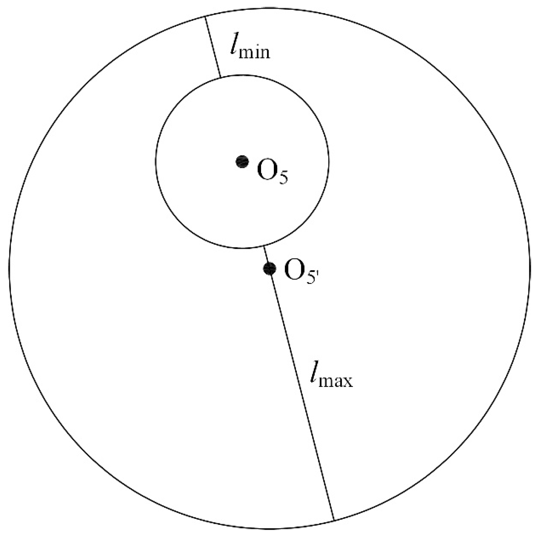
  • Fix the micrometer on the outer edge of the nut sleeve;
  • The micrometer rotates around the bolt;
  • Record the maximum and minimum readings of the micrometer as lmax and lmin, respectively.
The offset between the bolt and nut sleeve is as follows:
Δ P = l max l min 2 .
The test was repeated 20 times and the offset results are listed in Table 3.
In order to verify the reliability of the deep-water bolt flange automatic connection tool in an underwater environment, the pool test was carried out. The depth of the pool was 10 m. The pool test process was as follows:
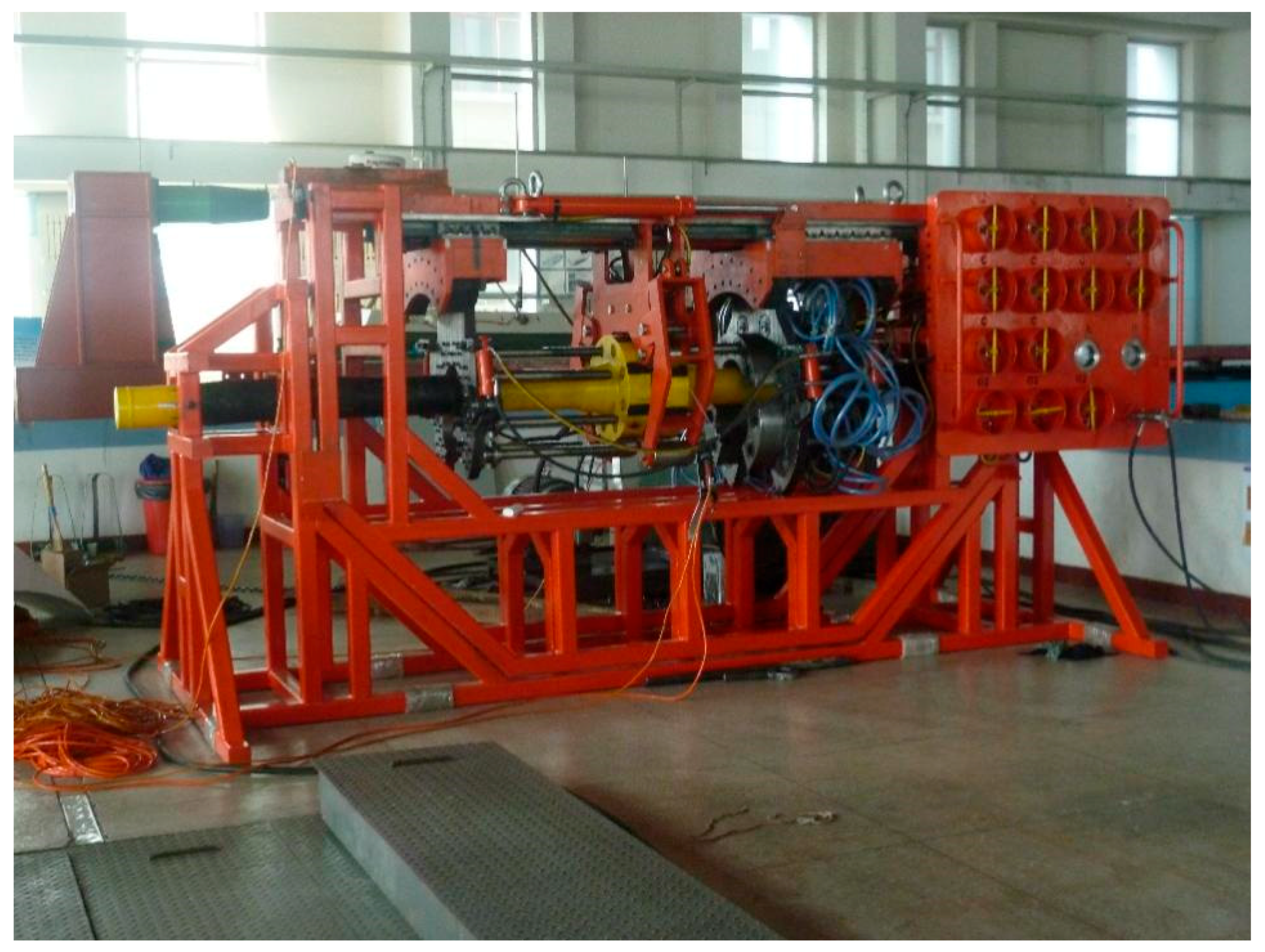
  • Assemble the deep-water bolt flange automatic connection tool on land;
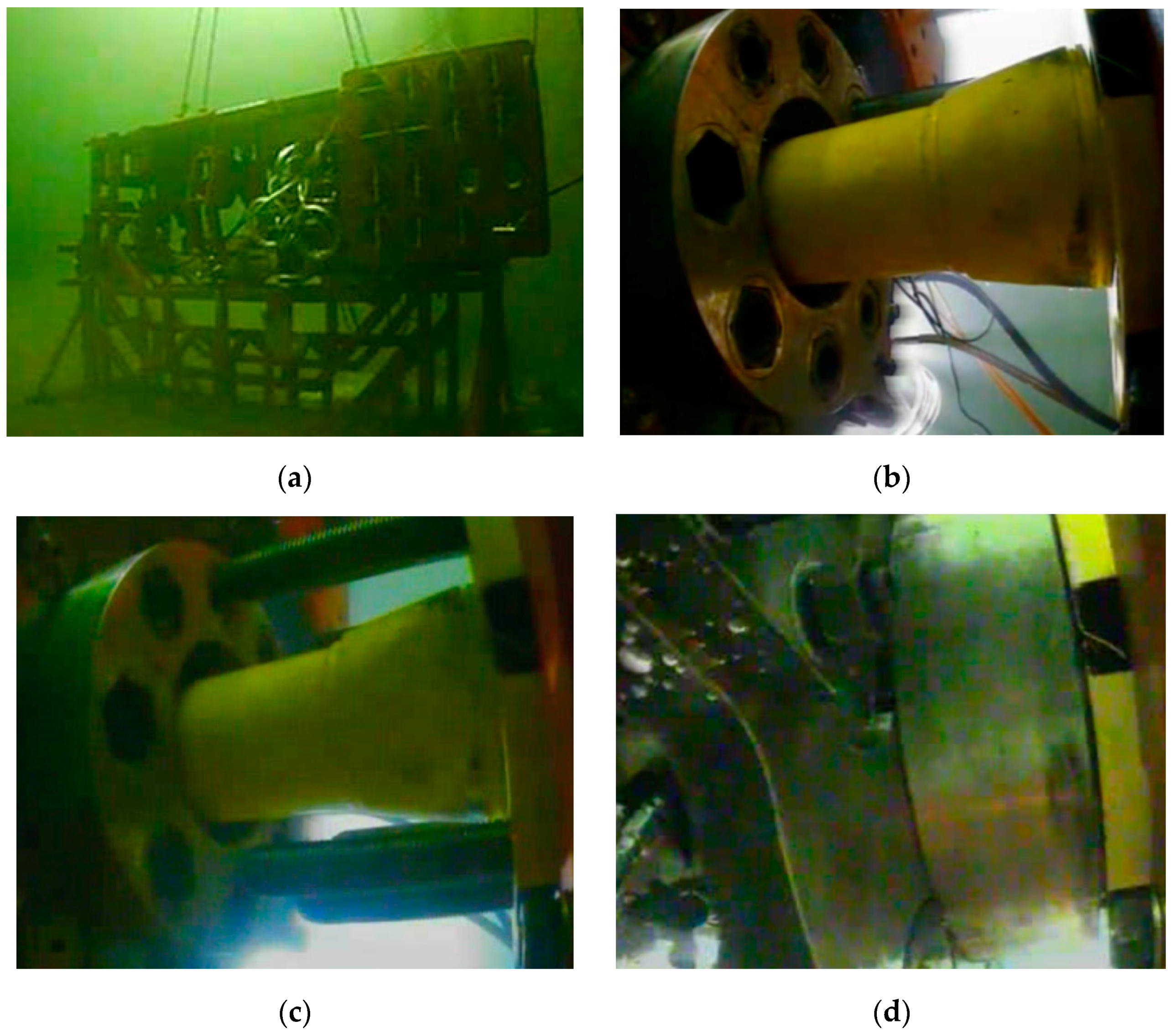
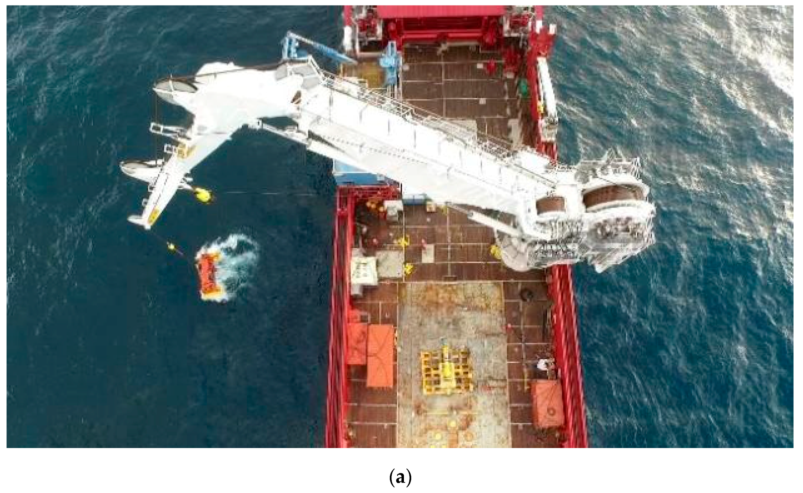
  • Use the crane to put the deep-water bolt flange automatic connection tool into the pool, as shown in Figure 18a;
  • Close the claw to hold the flange;
  • Close the bolt magazine, nut magazine and tensioner magazine, as shown in Figure 18b;
  • Adjust the position of the bolt magazine and the nut magazine to align the bolts and holes;
  • Move the bolt magazine forward and make the bolts go through the flange bolt holes, as shown in Figure 18c;
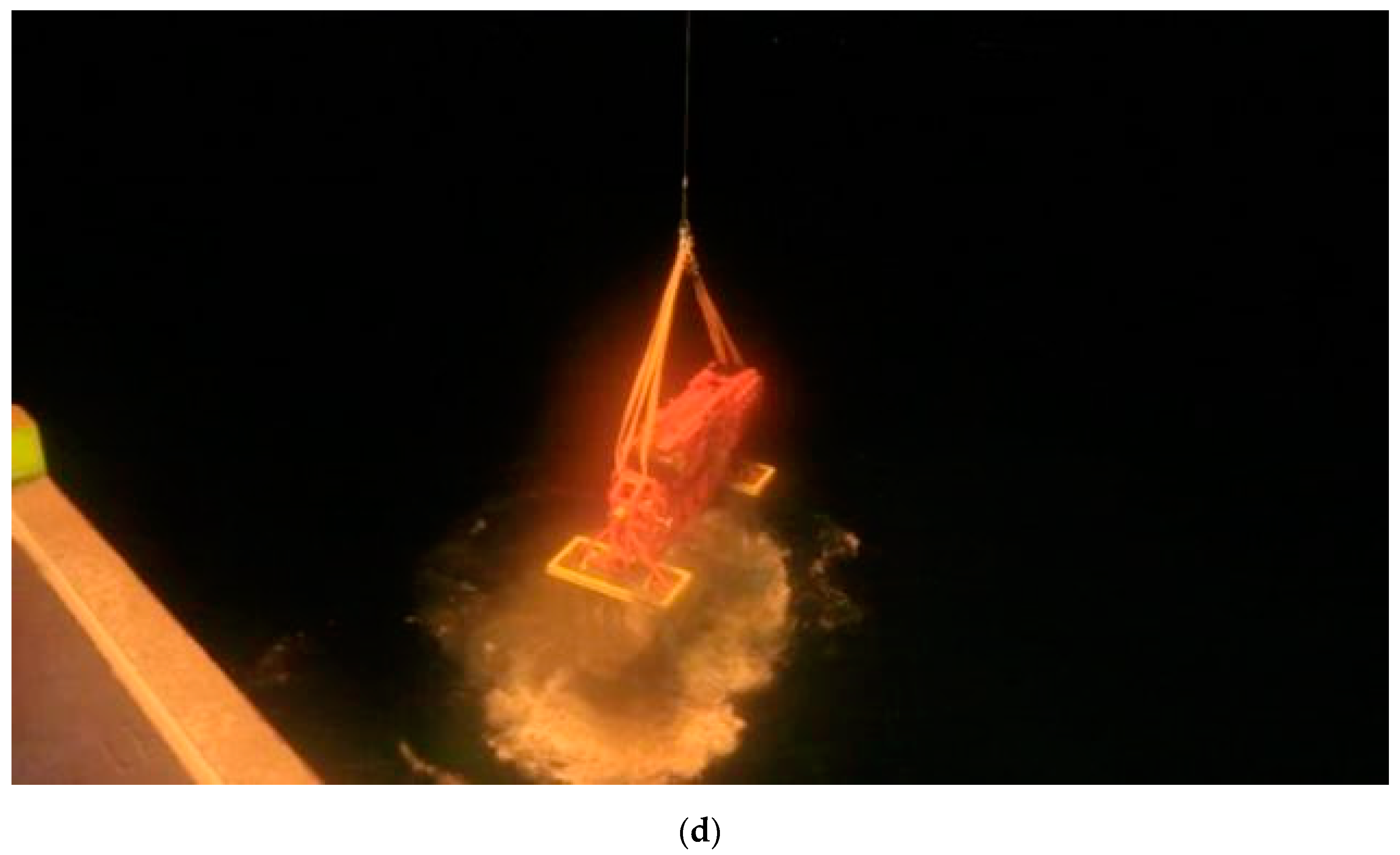
  • After the bolt magazine moves to the position, the nut magazine moves forward with the nut until the nuts contact the bolts; then, the motors rotate to tighten up the nuts, as shown in Figure 18d;
  • Open the claw, bolt magazine, nut magazine and tensioner magazine; lift up the deep-water bolt flange automatic connection tool back to land by crane and the test is complete;
  • Redo steps 1 to 8 10 times and record the results.
The 10 pool tests were smooth and successful.
To further verify the function of the deep-water bolt flange automatic connection tool, a sea test was conducted. The ship HYSY291 was used, which has the dynamic positioning system DP−2, the depth of the underwater operation of main crane was 2600 m, the ROV was TRITON XLX 28, which can work at 3000 m underwater. The water depth of the test point was 60 m. As shown in Figure 19, the sea test followed the same process as the pool test. The test results of the deep-water bolt flange automatic connection tool are listed in Table 4.

6. Conclusions

In this research, the kinematics modeling method was used to establish the error model of the deep-water bolt flange automatic connection tool. The alignment error of the bolt and nut was calculated through the computer simulation software, and the influence of each manufacturing accuracy on the alignment of the bolt and nut was analyzed. Based on the error matching design method, the manufacturing tolerances of parts are optimized with the priority sequence based on part size. The design of the deep-water bolt flange automatic connection tool was validated by land tests, pool tests and a sea test. The following conclusions can be drawn:
(1) The alignment error model of the deep-water bolt flange automatic connection tool can be created using the kinematics modeling method. The model can be used for an alignment error calculation with a given tolerance assignment.
(2) Based on the error matching design method, the manufacturing tolerances of the parts are optimized with the part-size-based priority sequence to ensure the total error is less than the allowable alignment error, 1.5 mm. The maximum alignment errors of the bolt and nut are 1.43 mm along the X−axis and 0.35 mm along the Y−axis, and the maximum combined alignment error is 1.44 mm; the maximum angle of the central lines of the bolt and nut is 0.10°, which meets the connection requirements of the bolt and nut. Δai contributes the most to ΔP, and particularly needs to be paid attention to in optimization; Δdi does not contribute to ΔPx, ΔPy, ΔP and θNB, and can be ignored.
(3) A land test, pool test and sea test have been carried out to validate the design. The land test was repeated 20 times and the pool test 10 times successfully to ensure the reliability of the connection tool. The sea test was successful as well and the connection tool worked well in subsea environment.
Further works need to be carried out, including uncertainty modelling and analysis, cost-based tolerance assignment and environment interferences, such as temperature and sea flow.

Author Contributions

Formal analysis, P.W. and H.G.; Methodology, P.W.; Writing—original draft preparation, P.W. and H.G.; Writing—review and editing, F.Y., Y.N., C.L., M.J., H.W. and K.X.; Validation, L.W. and F.Y.; Supervision L.W.; Funding acquisition, H.G. and F.Y. All authors have read and agreed to the published version of the manuscript.

Funding

This research was funded by National Natural Science Foundation of China (52001089); Heilongjiang Provincial Natural Science Foundation of China (LH2021E046); the central University Foundation of China (3072020CFT0704); Heilongjiang Provincial Natural Science Foundation of China (E2018021).

Acknowledgments

The authors gratefully acknowledge the financial support from National Natural Science Foundation of China (52001089); Heilongjiang Provincial Natural Science Foundation of China (LH2021E046); the central University Foundation of China (3072020CFT0704); Heilongjiang Provincial Natural Science Foundation of China (E2018021).

Conflicts of Interest

All the authors have read and approved this version of the article, and due care has been taken to ensure the integrity of the work. All the authors have no conflict of interest to declare.

Appendix A

Table A1. The tolerance of structural parameters.
Joint NumberLength Tolerance
(mm)
Assembly Tolerance
(mm)
Coaxiality Tolerance/Parallelism Tolerance
(mm)
Grade of ToleranceGrade of ToleranceGrade of Tolerance
fmIT5IT6IT7IT8IT5IT6IT7IT8
10.6001.600 0.0500.0800.1200.200
20.6001.6000.0550.0780.1250.1950.0400.0600.1000.150
30.4001.0000.0090.0130.0210.0330.0300.0500.0800.120
40.4001.0000.0130.0190.0300.0460.0300.0500.0800.120
50.6001.600 0.0200.0300.0500.080
1′0.6001.600 0.0400.0600.1000.150
2′0.6001.6000.0550.0780.1250.1950.0400.0600.1000.150
3′0.4001.0000.0110.0160.0250.0390.0300.0500.0800.120
4′0.4001.0000.0150.0220.0350.0540.0300.0500.0800.120
5′0.3000.600 0.0100.0150.0250.040
Table A2. The error limit of structural parameter.
Joint NumberΔdi
(10−2 mm)
Δai
(10−3 mm)
Δαi
(10−6°)
Δθi
(10−6°)
Grade of ToleranceGrade of ToleranceGrade of ToleranceGrade of Tolerance
fmIT5IT6IT7IT8IT5IT6IT7IT8IT5IT6IT7IT8
16016050801202007712318530877123185308
2601609513822534565971612426597161242
3401003963101153103171274411103171274411
4401004369110166107179286429107179286429
56016020305080375693148375693148
1′6016040601001508012020030080120200300
2′601609513822534565971612426597161242
3′4010041661051598013321332080133213320
4′4010045721151748013221231780132212317
5′3060101525408312520933383125209333

References

  1. Wang, L.; Wei, Z.; Yao, S.; Guan, Y.; Li, S. Sealing Performance and Optimization of a Subsea Pipeline Mechanical Connector. Chin. J. Mech. Eng. 2018, 31, 1–14. [Google Scholar] [CrossRef]
  2. Yun, F.; Wang, G.; Yan, Z.; Jia, P.; Xu, X.; Wang, L.; Sun, H.; Liu, W. Analysis of Sealing and Leakage Performance of the Subsea Collet Connector with Lens-Type Sealing Structure. J. Mar. Sci. Eng. 2020, 8, 444. [Google Scholar] [CrossRef]
  3. Zhang, L.; Zhao, C.; Liu, M.; Ru, C.; Zhu, Z.; Wang, L.; Liu, H. Mechanics analysis and performance research of hermetic rubber barrel for large diameter submarine pipeline stopper used in deepwater environment. Polym. Test. 2019, 79, 106014. [Google Scholar] [CrossRef]
  4. Li, Z.; Lin, Q.; Zhao, D.; Wang, L. The structural design and optimization for the inner-frame of subsea flange connection tool. Key Eng. Mater. 2009, 419, 197–200. [Google Scholar] [CrossRef]
  5. Shang, Z.; Ruan, W.; Qiao, H.; Bai, Y. Study on risk assessment and numerical simulation method of subsea manifold system. Ships. Offshore Struct. 2021, 16, 245–255. [Google Scholar] [CrossRef]
  6. Bouchonneau, N.; Sauvant-Moynot, V.; Choqueuse, D.; Grosjean, F.; Poncet, E.; Perreux, D. Experimental testing and modelling of an industrial insulated pipeline for deep sea application. J. Pet. Sci. Eng. 2010, 73, 111–112. [Google Scholar] [CrossRef]
  7. Wang, L.; Wang, W.; He, N.; Li, W.; Lin, Q. Design and simulation analysis of deep-sea flange connection tool. J. Harbin Eng. Univ. 2010, 31, 559–563. [Google Scholar] [CrossRef]
  8. Alliot, V.; Frazer, I. Tie-in system uses low-cost flanges on deepwater Girassol development. Oil Gas J. 2002, 10, 96–104. [Google Scholar] [CrossRef]
  9. Jia, Z.; Ma, J.; Song, D.; Wang, F.; Liu, W. A review of contouring-error reduction method in multi-axis CNC machining. Int. J. Mach. Tools Manuf. 2018, 125, 34–54. [Google Scholar] [CrossRef]
  10. Zhang, J.; Ding, J.; Li, Q.; Jiang, Z.; Ding, Q.; Du, L.; Wang, W. A new contouring error estimation for the high form accuracy of a multi-axis CNC machine tool. Int. J. Adv. Manuf. Technol. 2019, 101, 1403–1421. [Google Scholar] [CrossRef]
  11. Yang, X.; Seethaler, R.; Zhan, C.; Lu, D.; Zhao, W. A Novel Contouring Error Estimation Method for Contouring Control. Mechatronics. IEEE/ASME Trans. Mechatron. 2019, 24, 1902–1907. [Google Scholar] [CrossRef]
  12. Yang, J.; Rao, P.; Chen, B.; Ding, H.; Ai, W. Form error on-line estimation and compensation for non-circular turning process. Int. J. Mech. Sci. 2020, 184, 105847. [Google Scholar] [CrossRef]
  13. Liu, Z.; Dong, J.; Wang, T.; Ren, C.; Guo, J. Real-time exact contour error calculation of NURBS tool path for contour control. Int. J. Adv. Manuf. Technol. 2020, 108, 2803–2821. [Google Scholar] [CrossRef]
  14. Zhang, D.; Chen, H.; Wang, Z.; Zhao, H.; Ding, H. Variable-parameter-model-based iterative pre-compensation method of the tracking error. Mech. Syst. Signal. Proc. 2021, 156, 107687. [Google Scholar] [CrossRef]
  15. Denavit, J.; Hartenberg, R. A kinematic notation for lower-pair mechanisms based on matrices. ASME J. Appl. Mech. 1955, 23, 215–221. [Google Scholar] [CrossRef]
  16. Zheng, D.; Fei, Y.; Hu, Y.; Yang, R. Research on the Spatial Error Distribution Model of Flexible Coordinate Measuring Machines Based on Support Vector Regression. Adv. Mater. Res. 2011, 201–203, 2058–2062. [Google Scholar] [CrossRef]
  17. Zheng, D. Research on spatial error model of flexible coordinate measuring machine. J Mech. Eng. 2010, 46, 19–25. [Google Scholar] [CrossRef]
  18. Cheng, D. Limit and fit. In Handbook of Mechanical Design, 5th ed.; Chemical Industry Press: Beijing, China, 2007; Volume 1, pp. 92–154. [Google Scholar]
  19. Gafurov, A.; Jeong, J.; Park, P.; Kim, I.; Phung, T.; Kim, H.C.; Kang, D.; Oh, D.; Lee, T. Registration error analysis and compensation of roll-to-roll screen printing system for flexible electronics. Flex. Print. Electron. 2021, 6, 024003. [Google Scholar] [CrossRef]
  20. Qi, X.; Peng, Q.; Zhao, C. A new method based on attitude quaternion matching for transfer alignment. J. Astronaut. 2011, 32, 81–87. [Google Scholar] [CrossRef]
  21. Shi, H.; Zhao, Y. Error correction design. In New Idea and Methods of Error Design; Science Press: Beijing, China, 2007; pp. 112–113. [Google Scholar]
Figure 1. Deep-water bolt flange automatic connection tool.
Jmse 10 00064 g001
Figure 2. The structure of bolt magazine in the closed state (a) and open state (b).
Jmse 10 00064 g002
Figure 3. The structure of the nut magazine in the closed state (a) and open state (b).
Jmse 10 00064 g003
Figure 4. The coordinate system of deep-water bolt flange automatic connection tool.
Jmse 10 00064 g004
Figure 5. Position error caused by Δai.
Jmse 10 00064 g005
Figure 6. Angle error caused by Δai.
Jmse 10 00064 g006
Figure 7. Position error caused by Δαi.
Jmse 10 00064 g007
Figure 8. Angle error caused by Δαi.
Jmse 10 00064 g008
Figure 9. Position error caused by Δθi.
Jmse 10 00064 g009
Figure 10. Total position error.
Jmse 10 00064 g010
Figure 11. Total angle error.
Jmse 10 00064 g011
Figure 12. The process of tolerance assignment.
Jmse 10 00064 g012
Figure 13. Total position error after tolerance assignment.
Jmse 10 00064 g013
Figure 14. Total angle error after tolerance assignment.
Jmse 10 00064 g014
Figure 15. The deep-water bolt flange automatic connection tool.
Jmse 10 00064 g015
Figure 16. The land test.
Jmse 10 00064 g016
Figure 17. Measurement method of the offset between the bolt and nut sleeve.
Jmse 10 00064 g017
Figure 18. The pool test. (a) Put the deep-water bolt flange automatic connection tool into the pool; (b) Close the bolt magazine, nut magazine and tensioner magazine; (c) Move the bolt magazine; (d) Tighten up the nuts.
Jmse 10 00064 g018
Figure 19. Sea test. (a) Put the deep-water bolt flange automatic connection tool into the sea; (b) The deep-water bolt flange automatic connection tool in subsea environment; (c) ROV operation control panel; (d) Take the deep-water bolt flange automatic connection tool back to ship.
Jmse 10 00064 g019aJmse 10 00064 g019bJmse 10 00064 g019c
Table 1. The D–H parameters.
iai (mm)di (mm)αi (°)θi (°)
1065000
2001800
3292000
4−22201800
50−54000
1′0−50000
2′001800
3′375000
4′−30501800
5′012000
Table 2. Manufacturing tolerance grade assignment.
Joint NumberGrade of Tolerance of ΔdiGrade of Tolerance of ΔaiGrade of Tolerance of ΔαiGrade of Tolerance of Δθi
1mIT7IT 7IT 7
2mIT 5 IT 6IT6
3mIT 5IT 6IT 6
4mIT 5IT 6IT 6
5mIT 5IT 6IT 6
1′mIT 7IT 7IT 7
2′mIT 5 IT 6IT 6
3′mIT 5IT 6IT 6
4′mIT 5IT 6IT 6
5′mIT 5 IT 6IT 6
Table 3. The offset between the bolt and nut sleeve.
Test No.lmax (mm)lmin (mm)ΔP (mm)
146.55244.4481.052
246.45344.5470.953
346.44544.5550.945
446.45144.5490.951
546.45444.5460.954
646.52644.4741.026
746.52244.4781.022
846.46544.5350.965
946.45644.5440.956
1046.48344.5170.983
1146.49244.5080.992
1246.50244.4981.002
1346.56344.4371.063
1446.42544.5750.925
1546.46344.5370.963
1646.52544.4751.025
1746.56844.4321.068
1846.46244.5380.962
1946.41244.5880.912
2046.46944.5310.969
Table 4. The results of test.
Test NameTest TimesSuccess TimesSuccess Rate
Land test2020100%
Pool test1010100%
Sea test11100%
Publisher’s Note: MDPI stays neutral with regard to jurisdictional claims in published maps and institutional affiliations.

