
Development of a Towed Underwater Platform That Can Operate in a Marine Environment and Explore the Sea Bottom

 , , and
Abstract
:1. Introduction
2. Towed Underwater Platform
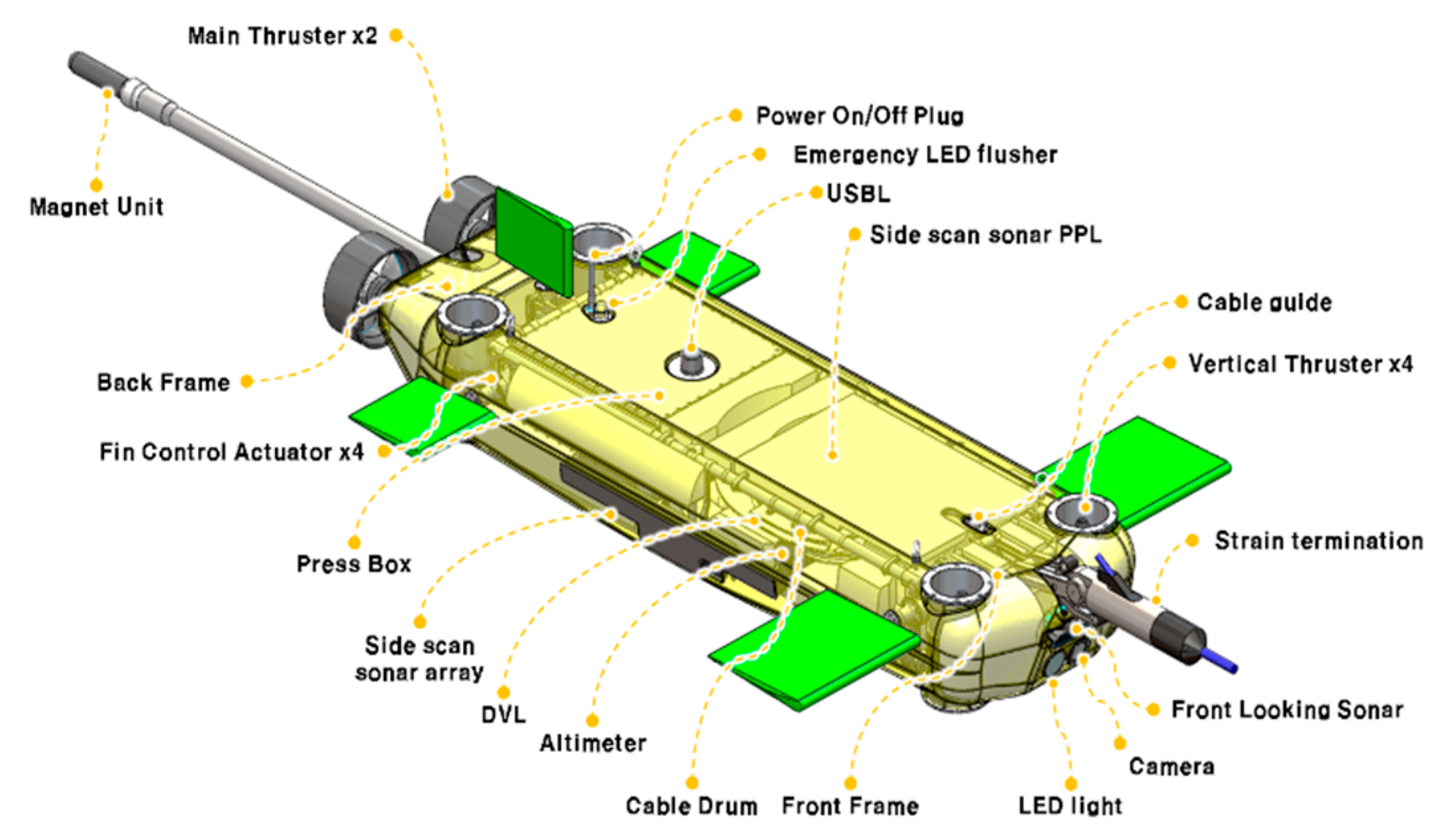
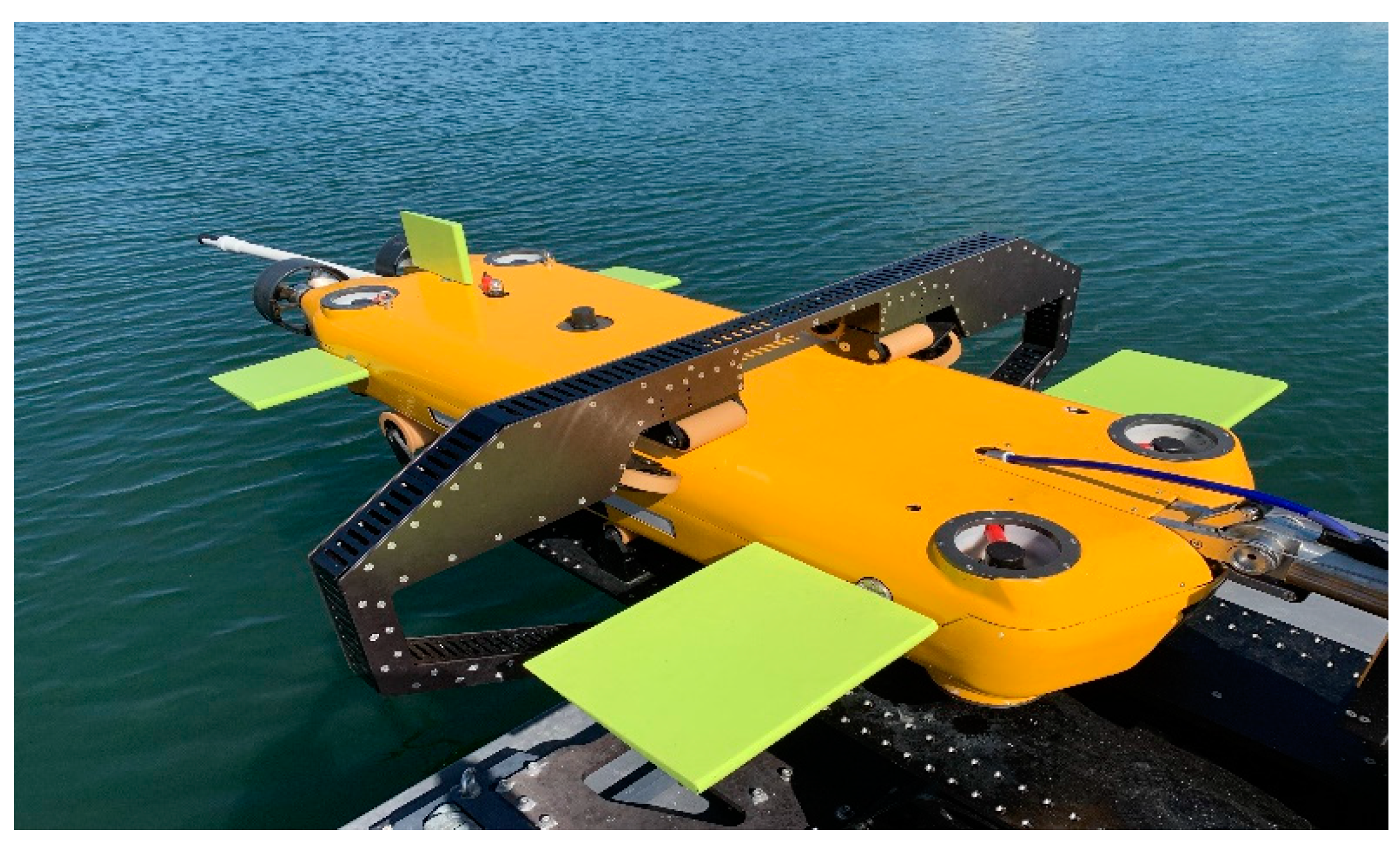
2.1. Hardware
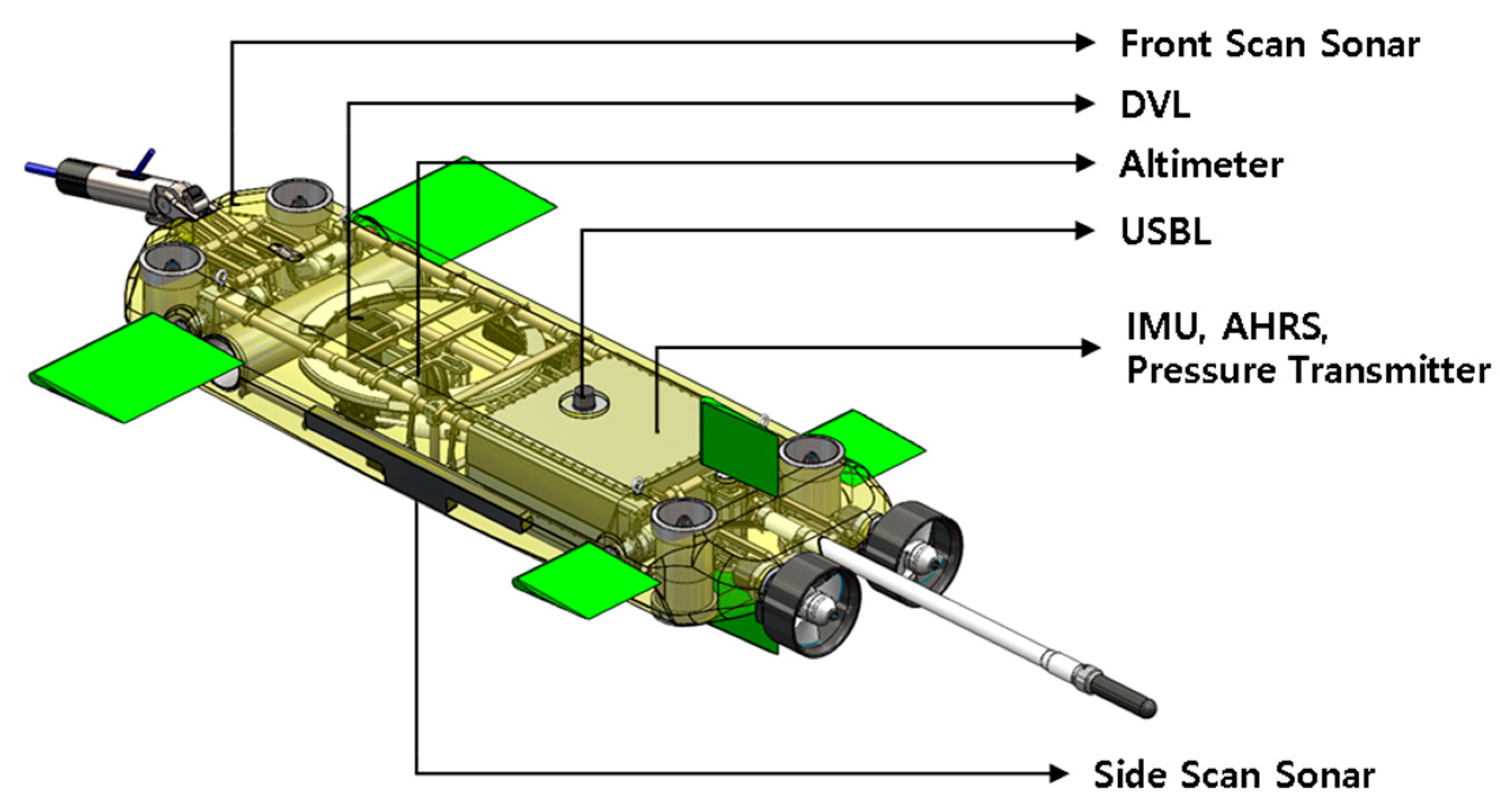
2.2. Sensors
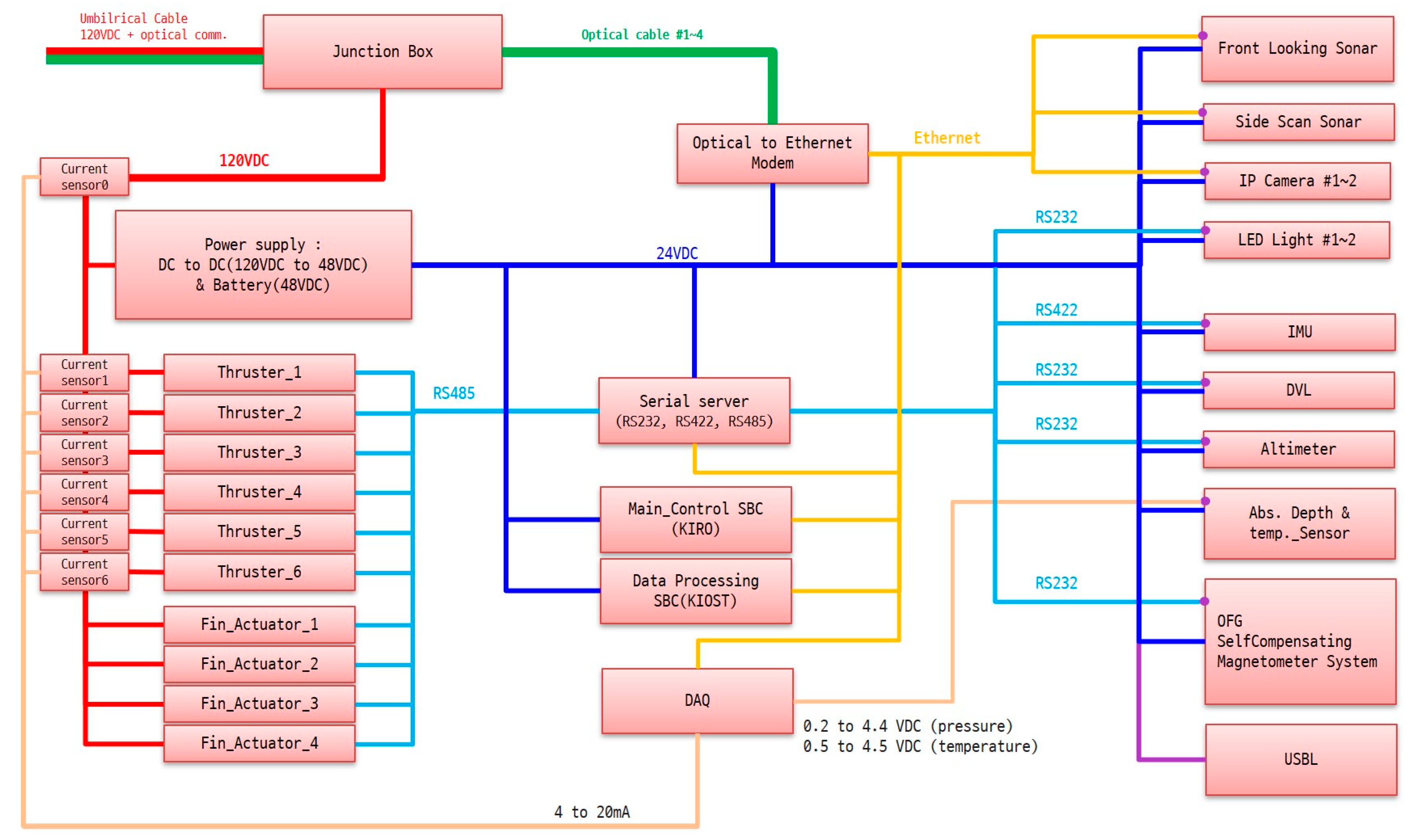
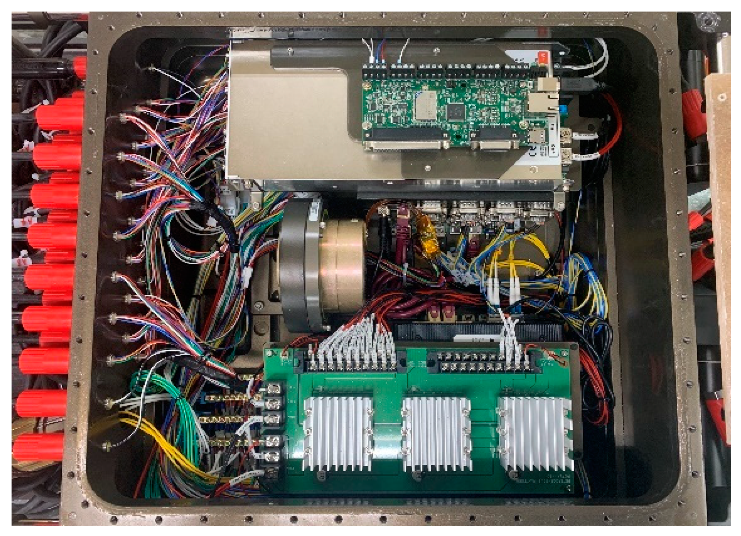
2.3. Electronic Design
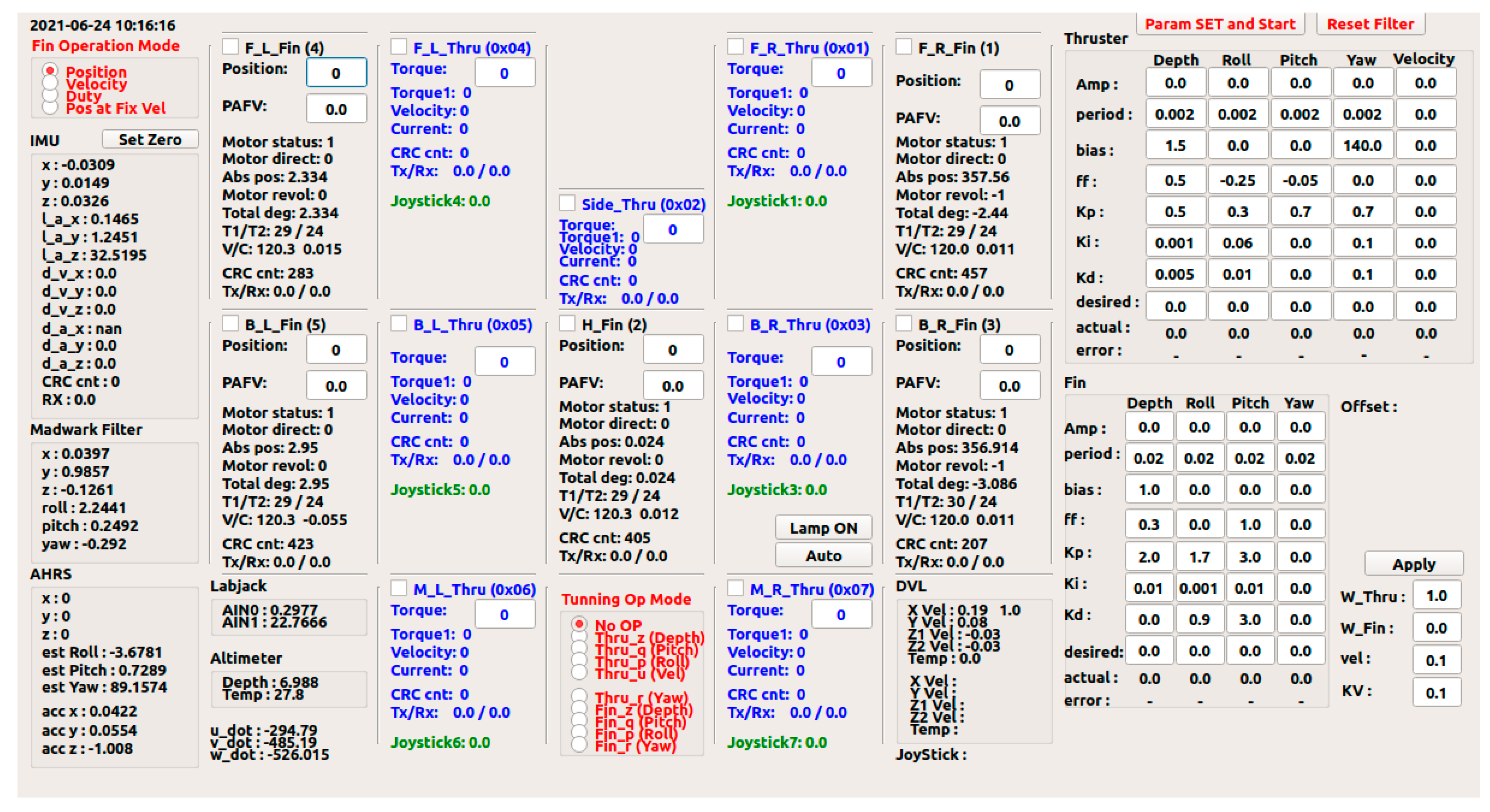
2.4. Software
3. Experiment
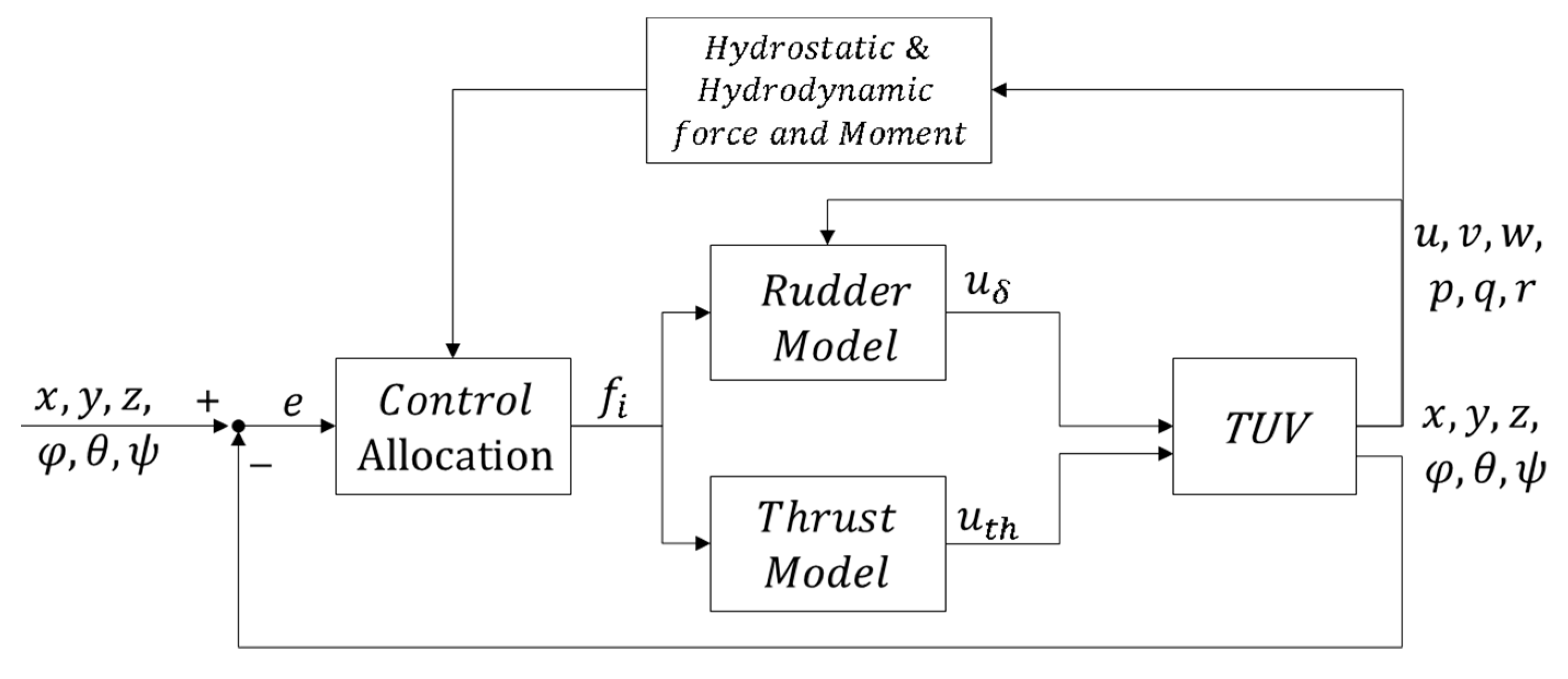
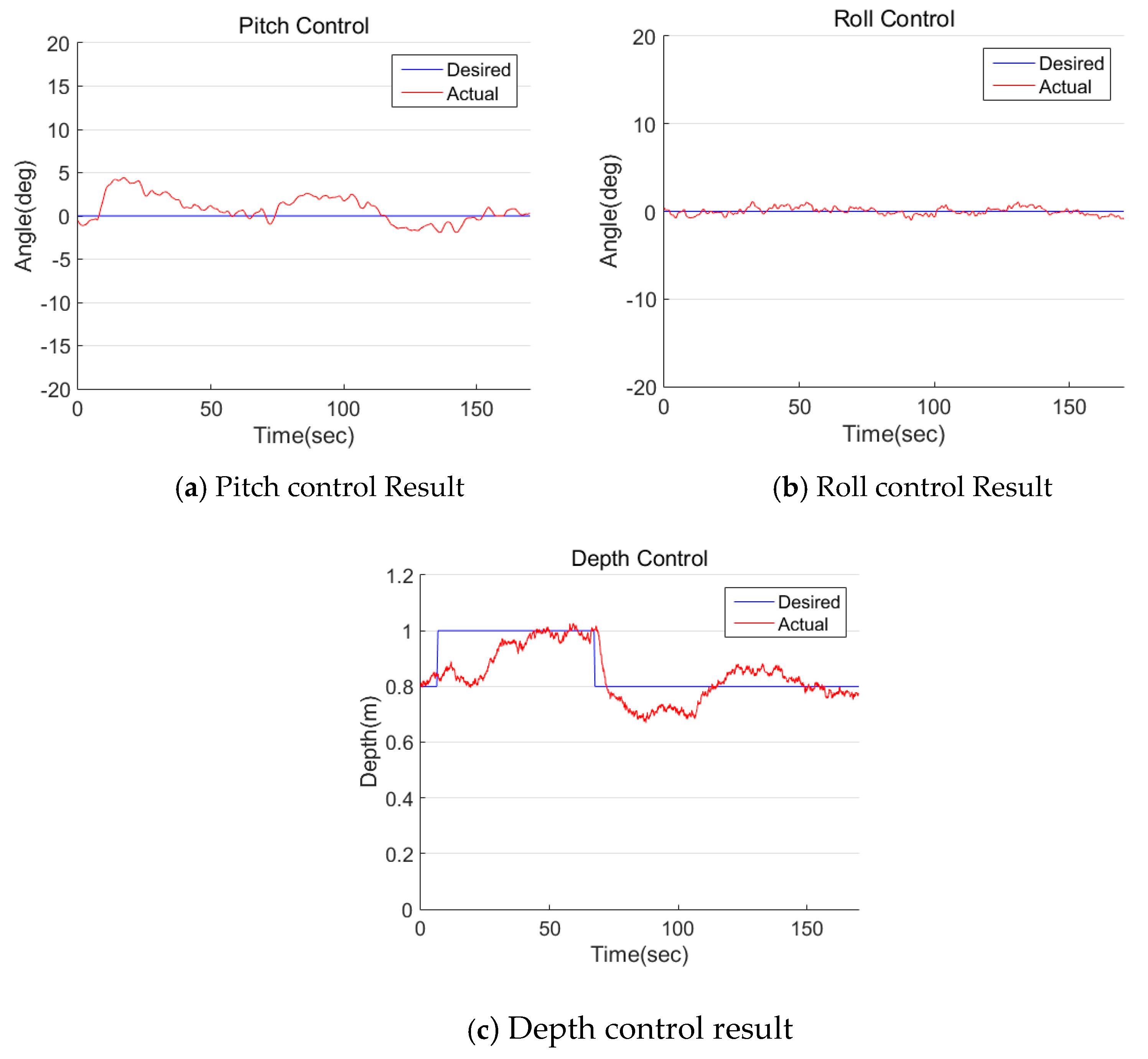
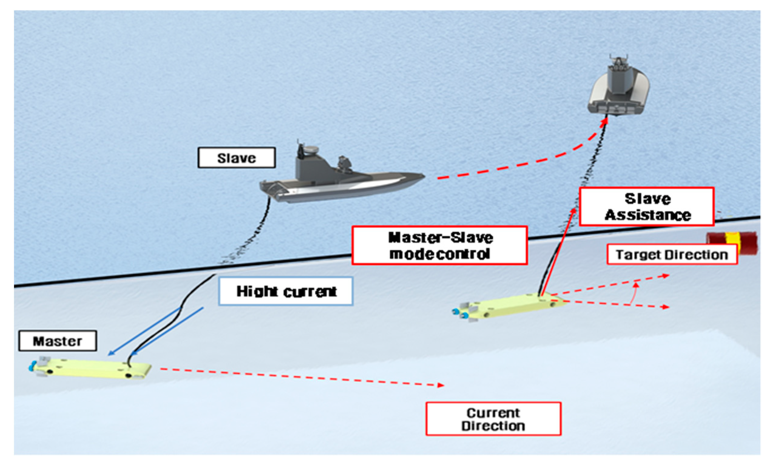
3.1. Control
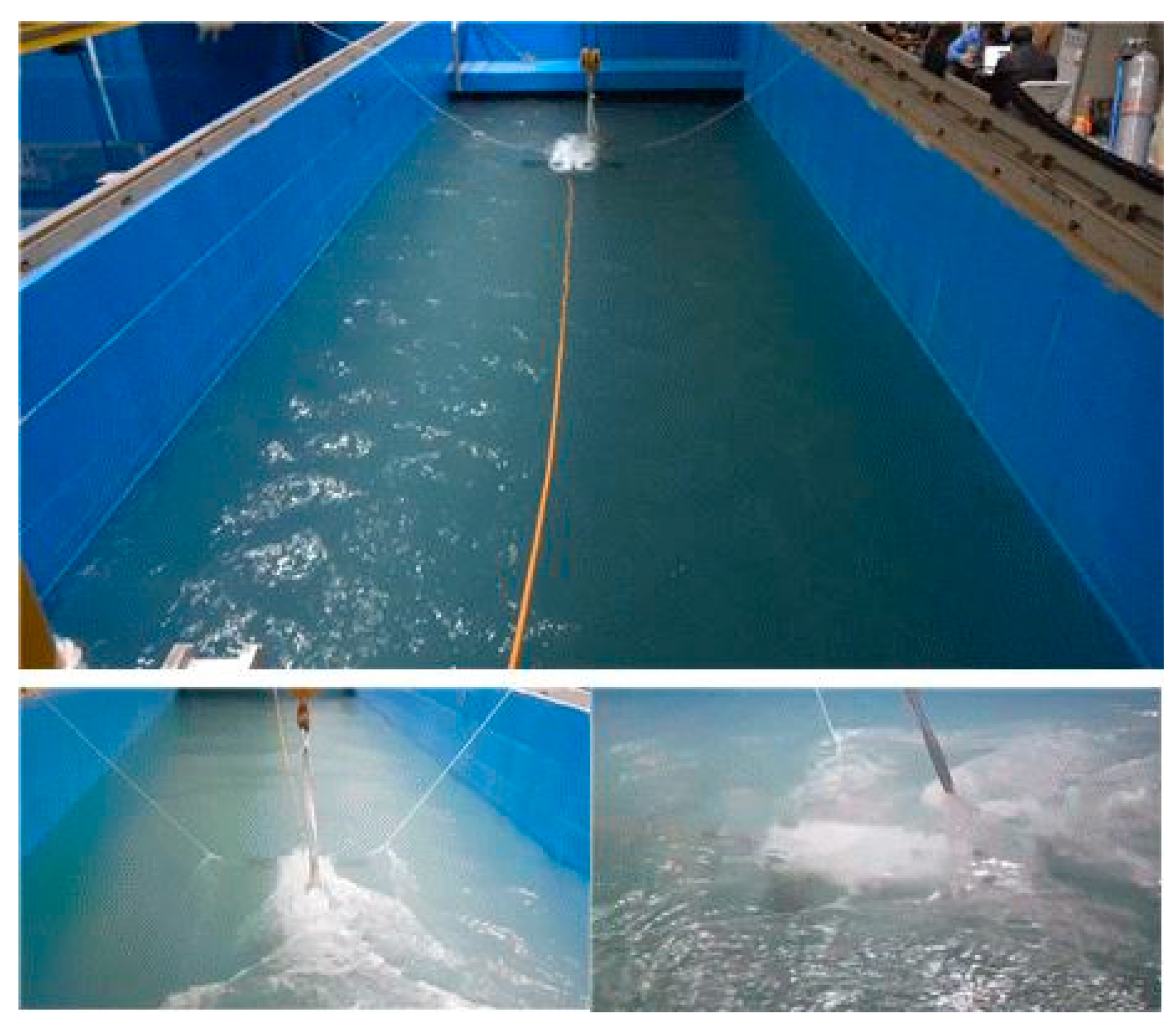
3.2. Water Tank Test
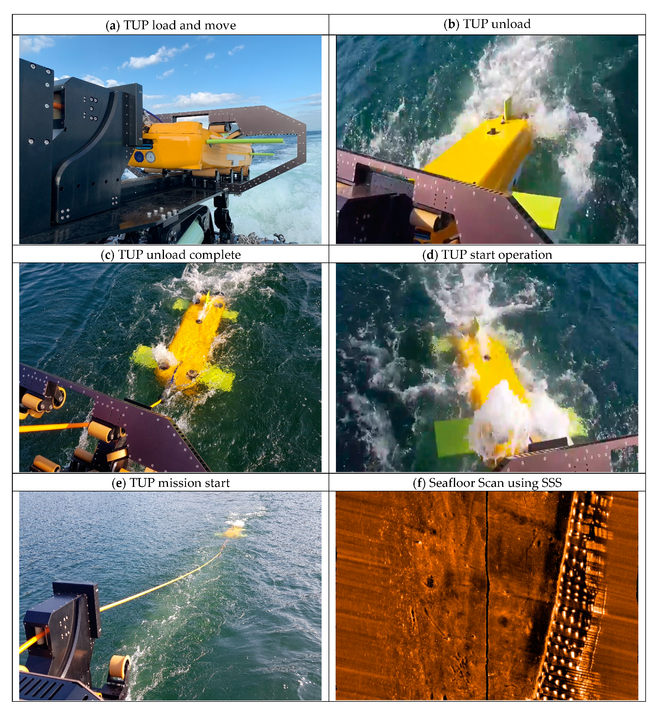
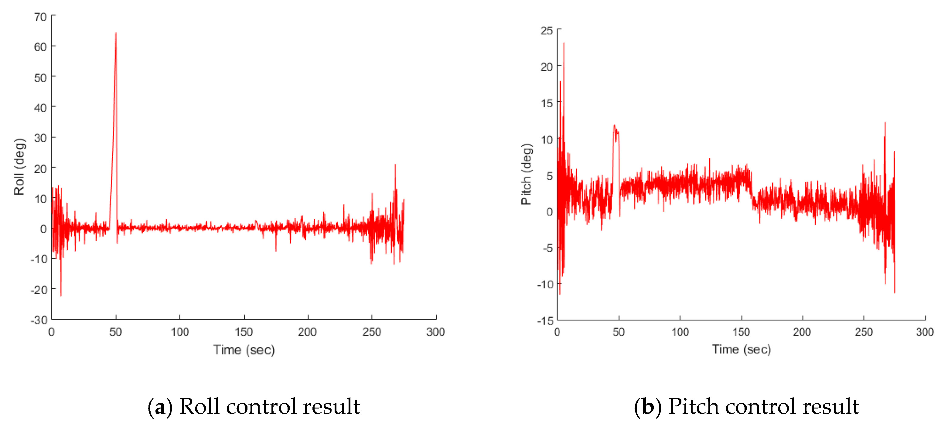
3.3. Actual Experiment Environment
4. Conclusions
Author Contributions
Funding
Institutional Review Board Statement
Informed Consent Statement
Data Availability Statement
Conflicts of Interest
References
- Fagundes Gasparoto, H.; Chocron, O.; Benbouzid, M.; Siqueira Meirelles, P. Advances in Reconfigurable Vectorial Thrusters for Adaptive Underwater Robots. J. Mar. Sci. Eng. 2021, 9, 170. [Google Scholar]
- Kim, K. Underwater navigation based on the multiple sensor fusion for the deep-sea UUV system, HEMIRE and HENUVY. In Proceedings of the OCEANS 2007—Europe, Aberdeen, UK, 18–21 June 2007; pp. 1–6. [Google Scholar] [CrossRef]
- Irani, R.A.; Limited, R.-R.C.; Kehoe, D.; Spencer, W.W.; Watt, G.D.; Gillis, C.; Carretero, J.A.; Dubay, R. Towards a UUV Launch and Recovery System on a Slowly Moving Submarine. In Proceedings of the Warship 2014: Naval Submarines & UUV’s, Bath, UK, 18–19 June 2014. [Google Scholar] [CrossRef]
- Sands, T. Development of Deterministic Artificial Intelligence for Unmanned Underwater Vehicles (UUV). J. Mar. Sci. Eng. 2020, 8, 578. [Google Scholar] [CrossRef]
- Brown, H.C.; Rodocker, J. Cooperative Underwater Survey with an L3Harris Iver UUV and Strategic Robotic Systems FUSION ROV. In Proceedings of the OCEANS 2019 MTS/IEEE SEATTLE, Seattle, WA, USA, 27–31 October 2019. [Google Scholar] [CrossRef]
- Park, D.; Jung, J.; Kwak, K.; Chung, W.K.; Kim, J. 3D underwater localization using EM waves attenuation for UUV docking. In Proceedings of the 2017 IEEE Underwater Technology (UT), Busan, Korea, 21–24 February 2017; pp. 1–4. [Google Scholar] [CrossRef]
- Pearson, D.; An, E.; Dhanak, M.; von Ellenrieder, K.; Beaujean, P. High-level fuzzy logic guidance system for an unmanned surface vehicle (USV) tasked to perform autonomous launch and recovery (ALR) of an autonomous underwater vehicle (AUV). In Proceedings of the 2014 IEEE/OES Autonomous Underwater Vehicles (AUV), Oxford, MS, USA, 6–9 October 2014; pp. 1–15. [Google Scholar] [CrossRef]
- Jung, D.W.; Hong, S.M.; heon Lee, J.; Cho, H.J.; Choi, H.S. A study on unmanned surface vehicle combined with remotely operated vehicle system. Proc. Eng. Technol. Innov. 2018, 9, 17–24. [Google Scholar]
- Vu, M.T.; Van, M.; Bui, D.H.P.; Do, Q.T.; Huynh, T.-T.; Lee, S.-D.; Choi, H.-S. Study on Dynamic Behavior of Unmanned Surface Vehicle-Linked Unmanned Underwater Vehicle System for Underwater Exploration. Sensors 2020, 20, 1329. [Google Scholar] [CrossRef] [Green Version]
- Lee, J.; Jin, H.S.; Cho, H.; Huang, J.; Jeong, S.K.; Ji, D.H.; Choi, H.S. A New Complex Marine Unmanned Platform and Field Test. J. Mar. Sci. Technol. 2020, 28, 9. [Google Scholar] [CrossRef]
- Cho, H.J.; Jeong, S.-K.; Ji, D.-H.; Tran, N.-H.; Vu, M.T.; Choi, H.-S. Study on Control System of Integrated Unmanned Surface Vehicle and Underwater Vehicle. Sensors 2020, 20, 2633. [Google Scholar] [CrossRef]
- Panish, R.; Taylor, M. Achieving high navigation accuracy using inertial navigation systems in autonomous underwater vehicles. In Proceedings of the OCEANS 2011 IEEE—Spain, Santander, Spain, 6–9 June 2011; pp. 1–7. [Google Scholar] [CrossRef]
- Pagliai, M.; Ridolfi, A.; Gelli, J.; Meschini, A.; Allotta, B. Design of a Reconfigurable Autonomous Underwater Vehicle for Offshore Platform Monitoring and Intervention. In Proceedings of the 2018 IEEE/OES Autonomous Underwater Vehicle Workshop (AUV), Porto, Portugal, 6–9 November 2018; pp. 1–6. [Google Scholar] [CrossRef]
- Vedachalam, N.; Umapathy, A.; Ramesh, R.; Babu, S.M.; Muthukumaran, D.; Subramanian, A.; Harikrishnan, G.; Ramadass, G.A.; Atmanand, M.A. Ampacity Derating Analysis of Winch-Wound Power Cables: A Study Based on Deep-Water ROV Umbilical. IEEE J. Ocean. Eng. 2015, 41, 462–470. [Google Scholar] [CrossRef]

| Item | Value |
|---|---|
| Size | 800 × 1800 × 320 mm |
| Weight (in air) | 150 kg |
| Search depth | 50 m |
| Search radius | 50 m |
| Operating depth | 50 m |
| Sensor types | 12 |
| Item | Model | Specification |
|---|---|---|
| SSS | Solstice Sidescan Sonar 8200 | 200-m scan range |
| FLS | Oculus M750d | 120 × 40-m scan range |
| USBL | Nano AvTrak6 OEM | 995-m depth rating |
| Magnetometer | OFG Self-Compensating Magnetometr System | 100 m, ±65 µT |
| DVL | DVL1000~300 m | 00.01 mm/s, 2–75 m altitude |
| Altimeter | Micron Echosounder | 0.1–120-m range |
| Depth | 4080BT010-FL1 | 0–10 bar |
| Temperature | 4080BT010-FL1 | −40–150 °C |
| IMU | Honeywell HG1700AG | Gyro 1 °/h, Acc 1 m·g |
| AHRS | 3DM-GX5-35 | Accelerometer: +/−8 g, Gyroscope: 300 °/s, Magnetometer: +/−8 Gauss |
| Camera | Ealge IPF 300 | 300-m depth rating, FHD |
| Light | Dragonfish T1K | 6000 K |
Publisher’s Note: MDPI stays neutral with regard to jurisdictional claims in published maps and institutional affiliations. |
© 2022 by the authors. Licensee MDPI, Basel, Switzerland. This article is an open access article distributed under the terms and conditions of the Creative Commons Attribution (CC BY) license (https://creativecommons.org/licenses/by/4.0/).
Share and Cite
Yun, S.-J.; Kim, H.-G.; Park, J.-W.; Lee, H.-J.; Kim, J.-C.; Hwang, J.-H.; Choi, Y.-H.; Lee, S.-J.; Ryu, J.-K.; Suh, J.-H.; et al. Development of a Towed Underwater Platform That Can Operate in a Marine Environment and Explore the Sea Bottom. J. Mar. Sci. Eng. 2022, 10, 66. https://doi.org/10.3390/jmse10010066
Yun S-J, Kim H-G, Park J-W, Lee H-J, Kim J-C, Hwang J-H, Choi Y-H, Lee S-J, Ryu J-K, Suh J-H, et al. Development of a Towed Underwater Platform That Can Operate in a Marine Environment and Explore the Sea Bottom. Journal of Marine Science and Engineering. 2022; 10(1):66. https://doi.org/10.3390/jmse10010066
Chicago/Turabian StyleYun, Sung-Jo, Hyo-Gon Kim, Jung-Woo Park, Hyo-Jun Lee, Jong-Chan Kim, Jeong-Hwan Hwang, Young-Ho Choi, Sin-Je Lee, Jae-Kwan Ryu, Jin-Ho Suh, and et al. 2022. "Development of a Towed Underwater Platform That Can Operate in a Marine Environment and Explore the Sea Bottom" Journal of Marine Science and Engineering 10, no. 1: 66. https://doi.org/10.3390/jmse10010066