Article

Design of a Disc-Shaped Autonomous Underwater Helicopter with Stable Fins

Ocean College, Zhejiang University, Zhoushan 316021, China
*
Author to whom correspondence should be addressed.
These authors contributed equally to this work.
J. Mar. Sci. Eng. 2022, 10(1), 67; https://doi.org/10.3390/jmse10010067
Submission received: 25 November 2021 / Revised: 14 December 2021 / Accepted: 4 January 2022 / Published: 5 January 2022
(This article belongs to the Special Issue State of the Art in Marine Robotics)

Abstract

:
The autonomous underwater helicopter, shortly referred to as AUH, is a newly developed underwater platform with a unique disc shape. An autonomous underwater helicopter with a suboptimal disc shape is presented in this paper. It adopts a multirotor configuration and stable fins to overcome the shape shortcoming for motion stabilization. Its motion analysis and mathematical model have been introduced accordingly. Computational Fluid Dynamics (CFD) simulation is carried out to evaluate fins’ hydrodynamic performance. Proportional integral derivative (PID) and sliding mode fuzzy (SMF) control are adopted for controller design. Finally, the controller is applied on this AUH and extensively tested in various simulations and experiments, and the results illustrate the high stabilization and robustness of the controller and the hovering stability and manoeuvrability of AUH.

1. Introduction

Autonomous underwater vehicles (AUVs) are used extensively in deep-sea exploration, scientific research, and rescue operation [1]. They are also employed in commercial underwater applications, such as laying underwater cables, collecting marine samples, and building underwater structures [2,3]. Traditional AUVs have good hydrodynamic performance and low resistance; thus, they can achieve long operation time and long-distance navigation benefit [4]; but on the other hand, it has the drawbacks of poor manoeuvrability and hovering ability [5]. With the development of ocean observation and sea equipment, the demand for close seabed and near ice sheet exploration calls for new requirements for AUVs [6], which can hover near the surface and have good manoeuvrability and stability. Existing AUVs are not suitable for such operations since they need to move forward to stay submerged and cannot work at a closer distance from the seafloor. To undertake this, Sparus II AUV [7] applies a vertical thruster in the central part of the vehicle to get better hovering ability and Seabed AUV [8] uses a double-hull structure to obtain stable underwater performance.
Disc shape is unique and its symmetrical structure has zero radius of gyration which could allow vehicles to explore from all angles and directions within a narrow space. Although the fluid resistance in the vertical direction will increase the energy consumption and decrease the velocity, it can also bring stability [9]. The first disc-shaped AUV was Discuz of the Webb Corporation in the United States [10] and there are LUNA [11] and BOOMERANGE [12] of the Research Institute for Applied Mechanics, Kyushu University, and a disc-shaped underwater glider of Dalian Maritime University [13]. This research on disc-shaped AUVs is mainly in the laboratory and they cannot yet carry out the complex and flexible planar movement.
To meet the needs of near-seafloor and under-ice observations, further research and exploit the properties of the disc shape, Chen first proposed the concept of the autonomous underwater helicopter (AUH) in 2017 [6]. It is a new member of the AUV family with a unique disc shape; much research has been conducted over the last few years such as parametric design [14], wave impact [15], and so on [16]. This vehicle does not need to move to stay submerged compared with traditional AUVs. In this context, we designed an autonomous underwater helicopter (AUH) with a suboptimal shell due to size restrictions for under-ice applications. A multirotor configuration and stable fins are built to reduce the adverse effects of shape. The fluid analysis demonstrates fins’ effects on horizontal motion. A Proportional integral derivative (PID) and sliding mode fuzzy (SMF) controller is developed and applied to control underwater motion with five degrees of freedoms (DOFs). After that, simulations were carried out and the underwater experiment results show that the AUH has manoeuvrable motion and stable hovering ability.
This paper is organized as follows. The following section describes the hydrodynamic analysis and dynamic model of AUH. Section 3 details the design of a multirotor controller and a simulation test is then executed. Section 4 presents the underwater experiments. Section 5 presents the summary and conclusions.

2. Dynamic Model of AUH

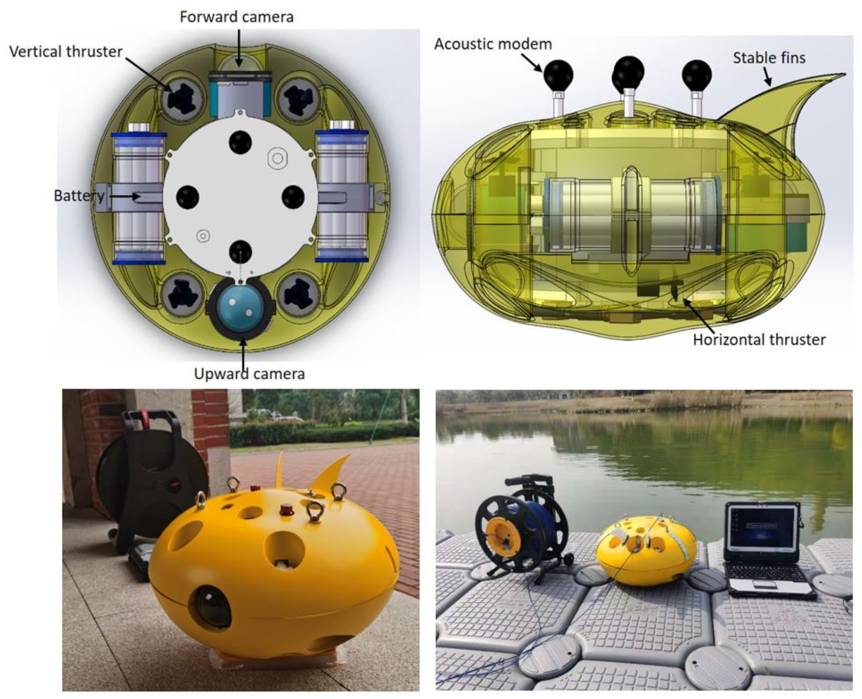
2.1. Mechanical Structure of AUH

The AUH presented in this paper is shown in Figure 1; it is designed for under-ice and near-seafloor observation with strict size restrictions to be deployed and recovered vertically through a small-diameter hole drilled in the ice shelf. This vehicle has a 42 cm diameter, 23 cm height and 14 kg weight, and the maximum design depth is 300 m. According to the fluid analysis in [14], the optimal diameter to height ratio is around 2.6. In this vehicle, the ratio is 1.82, this suboptimal disc shell would cause instability in attitude control. The ratio in the previous work [16] is 2.3, which can be considered as an ideal ratio, and it used four thrusters for four DOFs control. In [17], the vehicle is spherical and uses eight thrusters for six DOFs control. We do not have enough space for more thrusters, to solve the problems caused by suboptimal shape we made the following design:
  • A multirotor configuration used six thrusters for five DOFs of the surge, heave, roll, pitch, and yaw;
  • Two fins at the rear are used to make stability when moving forward.
Four thrusters for vertical control are placed in a square formation with equal distance from the vehicle’s center similar to a quadcopter [18], they can control heave, roll, pitch independently. Two thrusters for horizontal control are placed in the lower position for surge and yaw. This configuration could help reduce the diameter, and pitch control can offset the rotation torque produced by horizontal thrusters. Fins are mainly used for yaw stabilization during navigation.
This vehicle is equipped with several sensors: an attitude and heading reference system (AHRS), a deep sensor, a temperature sensor, two cameras for underwater photography, and a self-developed acoustic system for absolute positioning. Users can get real-time data through an optical fiber connection. Without an extra payload, at 1 kn surge speed, it would allow a 5 h operation at least. In this paper, we focus on the effect of the fins on yaw dimension during horizontal motion and the multirotor configuration’s overall control effect. A computational fluid dynamics (CFD) simulation is conducted, motion analysis is discussed in the following. The analysis of the whole suboptimal shell should be another separate computational fluid dynamic work.
Figure 1. Autonomous underwater helicopter.
Jmse 10 00067 g001

2.2. CFD Simulation

During underwater navigation, various uncertainties can cause changes in the vehicle’s attitude, such as current disturbances and inconsistencies in propulsion power output. Disc shape has a complete circumferential symmetry in the horizontal direction, which makes it subject to the same forces in all directions of horizontal motion.
To enhance stability during movement, we designed fins at the rear of the shell. The angle between two fins is 36°, and the surface area of a single fin is 69.43 cm2. CFD simulations of the suboptimal shell with fins are shown in Figure 2, Figure 3, Figure 4 and Figure 5. The shell rotated at six different angles to assess the effect of water flow on it, and the water flows at 0.5 m/s with a fixed direction. The results show that the force acting on the shell’s circumference does not change while the force acting on the fins increases as the shell rotates. The force on the shell’s circumference only affects the motion along the direction of the water flow, while the force acting on the fins can also produce a torsional moment to affect rotation motion in the vertical plane. The CFD simulation results of the suboptimal shell without fins are shown in Figure 6, the water flow rate is 0.5 m/s. The resistance acts in the same direction with the same size regardless of how the shell rotates. This feature can bring flexibility, but it also brings more instability under disturbances. After adding the stable fins it requires more torque to counteract water resistance for steering, and it would have less yaw angle oscillation in the presence of disturbances since the moment of the water on the fins can be seen as a reversion moment.
The water resistance is shown in Figure 7. These fins can create up to 0.12 N·m additional torque at 72°. The resistance will increase significantly with the increase of yaw angle in the range of 18–72° compared to the shell without fins. That means AUH would be more stable and can back to the original course faster if the disturbance changes the yaw angle in the range of 18−72° along the current course. This section analyzes the fins’ effect on the yaw angle during horizontal motion, and an underwater experiment is executed to evaluate the actual control impact in Section 4.

2.3. Motion Analysis

The inability to independently control the attitude angle and liner motion of AUH would negatively influence overcoming the effect of attack angle and flow disturbance. To overcome this, we designed a multirotor configuration with six thrusters (see Figure 8.) to control five DOFs especially independently control pitch, roll, and surge motion. Adjacent to the four vertical thrusters adopt different rotating directions to eliminate the effect of anti-torque (i.e., M 1 + M 2 + M 3 + M 4 = 0), and the same is true for two horizontal thrusters. The motion mode of this multirotor configuration is as follows.
  • Heave
    Four vertical thrusters 1, 2, 3, and 4 rotate simultaneously at the same speed.
  • Roll
    Increasing the rotating speed of 1 and 2 and make Ω 1 = Ω 2 , Ω 3 = Ω 4
  • Pitch
    Increasing the rotating speed of 1 and 4 and make Ω 1 = Ω 4 , Ω 2 = Ω 3
  • Yaw
The quadcopter uses the difference in anti-torque to steer yaw angle because the rotor has a large area propeller and very high rotating speed; therefore, it can produce enough torsion. This AUH’s thruster has a small area propeller and low speed; thus, it is challenging to use anti-torque for yaw steering. Here we use two horizontal thrusters to achieve yaw control, increasing the rotating of 6 to produce a thrust difference between 5 and then making a clockwise turning motion (this will produce a difference between M 5 and M 6 but it can be ignored relative to the overall quality).
  • Surge
    Increasing the rotating speed of 5 and 6.
Figure 8. Rotor distribution. f 1 ,   f 2 ,   f 3 ,   f 4 ,   f 5 ,   f 6 are the thrust produced by propeller 1, 2, 3, 4, 5, 6. Ω 1 ,   Ω 2 ,   Ω 3 ,   Ω 4 ,   Ω 5 ,   Ω 6 presenting the rotating speed and direction. M 1 , M 2 , M 3 , M 4 ,   M 5 ,   M 6 present the anti-torque produced by the water, opposite the rotating direction.
Jmse 10 00067 g008
In general, the four vertical thrusters oversee heave, roll, pitch, and horizontal thrusters control surge and yaw; change of any one of them does not affect the others’ states. Finally, it is worth noting that the vehicle does not have the sway DOF, its hovering and manoeuvrable capability is enough for most applications.

2.4. Mathematical Modelling

The coordinate frame system is present in Figure 9. The absolute linear position of this vehicle is defined in the inertial frame with ξ = x y z T and the angular position is defined in the inertial frame with η = ϕ θ ψ T . The origin of the body frame is considered in the center of mass of the vehicle. The linear velocities are determined by V B = u v w T and the angular velocities by ν = p q r T . The rotation matrix from the body frame to the inertial frame is R , and the rotation matrix R is orthogonal, thus R 1 = R T which is the rotation of the rotation matrix from the inertial frame to the body frame.
R = cos ψ cos θ cos ψ sin θ sin ϕ sin ψ cos ϕ cos ψ sin θ cos ϕ + sin ψ sin ϕ sin ψ cos θ sin ψ sin θ sin ϕ + cos ψ cos ϕ sin ψ sin θ cos ϕ cos ψ sin ϕ sin θ cos θ sin ϕ cos θ cos ϕ
The disc shape has a symmetric structure, so the inertia matrix is diagonal J , in which J x = J y .
J = J x 0 0 0 J y 0 0 0 J z
AUH is assumed to be a rigid body and we use Newton-Euler equations to describe its dynamic [19]. The linear dynamic equation in the inertial frame is written as:
m ζ ¨ = G F f l o a t R R t R T B
where G donates the gravity force, F f l o a t is the vehicle underwater buoyancy, R t is the water resistance generated by vehicle movement. Generally, the underwater resistance can be written as R t = R f + R p v = C t ρ v n S / 2 , C t is total water resistance coefficient,   v is flow velocity, S is wet surface area, T B is the total thrust.
In the body frame, the angular acceleration of the inertia J ν ˙ , the centripetal forces ν J ν , the gyroscopic moment M g y r o and the flow resistance moment M f l o w are equal to the rotor torque τ.
J v ˙ + v Jv + M g y r o + M f l o w = τ
where M g y r o = ν H i , H i is the moment of momentum produced by propeller.   M f l o w = C w R v , C w is the proportional coefficient of water resistance torque and rotational angular velocity, R is the radius of the vehicle.
The significant feature of this vehicle is the ability to achieve a stable underwater movement, this is the foundation of other motion. Therefore, the dynamic model can be simplified since roll and pitch would maintain near zero during operation.
In summary, the dynamic model of AUH is shown as follows:
x ¨ = K T m Ω 5 2 + Ω 6 2 c o s ψ + 1 2 m C t x ρ S 1 y ˙ 2 s i n Ψ x ˙ 2 c o s Ψ y ¨ = K T m Ω 5 2 + Ω 6 2 s i n ψ 1 2 m C t y ρ S 1 y ˙ 2 c o s Ψ + x ˙ 2 s i n Ψ z ¨ = K T m Ω 1 2 + Ω 2 2 + Ω 3 2 + Ω 4 2 1 2 m C t z ρ z ˙ 2 S 2 + K b g ϕ ¨ = 2 2 J x K T l ( Ω 1 2 Ω 2 2 Ω 3 2 + Ω 4 2 ) J r ϕ ˙ J x ( Ω 1 Ω 2 + Ω 3 Ω 4 ) C w J x R ϕ ˙ θ ¨ = 2 2 J y K T l ( Ω 1 2 + Ω 2 2 Ω 3 2 Ω 4 2 ) + J r θ ˙ J x ( Ω 1 Ω 2 + Ω 3 Ω 4 ) C w J y R θ ˙ ψ ¨ = K T l J z ( Ω 5 2 Ω 6 2 ) C w J z R ψ ˙
where K b is the buoyancy coefficient, it represents the difference between gravity and buoyancy,   K T is the thruster coefficient, J r is the inertia of the propeller, l is the value of force arm,   C t x = C t y is the resistance coefficient in the horizontal plane, C t z is the resistance coefficient in the vertical direction and according to the hydrodynamic analysis of the disc type underwater vehicle [20] C t z C t x , S 1 is the vehicle horizontal wet surface area, S 2 is the vertical wet surface area.

3. Controller Design and Simulation

3.1. Controller Design

The control objective is to achieve stable deep control and accurate attitude tracking. The vertical motion of AUH is similar to a quadcopter [21,22], so a PID controller would be a good choice for AUH to undertake the vertical motion control. The horizontal motion of AUH is much more complicated, the vehicle will be affected by the flow resistance and uncertain disturbances. The suboptimal disc shape causes instability, and the stable fins produce additional resistance torque in the meanwhile. To solve the horizontal motion control problem, we use the SMF control method, sliding mode control is known as the advantage for nonlinear system control and has good robustness, fuzzy logic control has the property of approximation. This controller has the robustness of sliding mode control and uses fuzzy logic control to achieve compensation for disturbances, and those properties make it ideal for AUH robust control.
From formula (5) we can get the SMF controller of yaw motion:
u = J z C w J z R ψ ˙ ψ ¨ d + c e ˙ + K ˜ t s a t s / K T l
where K ˜ t is the integration of fuzzy logic control output to estimate the trend of disturbances. The fuzzy logic control input and out is shown in Figure 10 and Figure 11. s a t s is the saturation function that can bring a boundary layer to the switch surface [23]:
s a t s = 1           s > k s         s 1         s <           k = 1  
where determine the thickness. Outside this layer controller would adopt switch control but inside layer use linearized feedback control, which could reduce the chattering.

3.2. Simulation

The simulation test is performed by applying different attitude angles and depth as input to the control system, the SMF controller is contrasted with a standard sliding mode controller, which does not adopt fuzzy logic control and saturation function; the results are presented in Figure 12, Figure 13, Figure 14, Figure 15 and Figure 16.
Firstly, the yaw angle and depth are set as 20°, 40°, 60°and 10 m, 20 m, 30 m, respectively, pitch and roll are set to constant zero. Figure 12 depicts the attitude and depth control result of AUH. Secondly, the comparative test of SMF controller and standard sliding mode controller is conducted. We adopt the gauss function to simulate abrupt environmental disturbance in this test. The SMF controller uses fuzzy logic control to make a dynamic compensation and a saturation function to reduce system chattering; the standard sliding mode controller has a constant compensation and uses a sign function. Disturbance has the max value of 200 at 5 s, the constant compensation value is set to 210. It can be observed in Figure 13, Figure 14, Figure 15 and Figure 16 that the SMF controller has a stable tracking result than the standard sliding mode controller, the designed fuzzy logic control system can improve system stability. Besides, the control output of the SMF controller is much smoother than the standard sliding mode controller, and the results reveal that fuzzy logic control and saturation function can sufficiently reduce the chattering of the system under uncertain disturbances. Based on the analysis of the simulation results, it can be concluded that the controller could make dynamic compensation to uncertain disturbance and the control system has quick response time and low chattering.

4. Pool Experiments

After simulation, we then conducted serial underwater experiments, we used the water pool of Zhejiang University Ocean College, which has 45 m diameter and 6 m depth (see Figure 17). In general, there are two usage scenarios for AUH, one scenario is to hover at a fixed position for some observing purpose and another one is to navigate according to a set route. Both scenarios need hovering stability and manoeuvrability.
We first carried out experiments in hovering mode. We set four different depths and yaw angles, respectively. The experiments results show in Figure 18 and Figure 19. It can be seen that the vehicle has good deep and attitude angle control ability, it can maintain at different depths and attitude angles stably and we set roll and pitch angles at constant zero. It takes a relatively long time to reach the set depth and the simulation coincides with test trends. It approximately takes an average of 30 s to make a 1 m deep change and 1 s to achieve a 3° change of yaw. The multirotor controller has a low steady-state error of deep and attitude control which is 0.02 m and 2°, respectively, in hovering mode. This can ensure a stable underwater observation at a fixed position.
After hovering mode experiments, we carried out the navigation mode tests. At this mode our vehicle will navigate at a constant speed, it needs to maintain its current depths and attitude angles, execute quick and precise turnings. The manoeuvrability of underwater navigation is another advantage of AUH over traditional AUVs. At first, we made a set of comparative experiments to further verify the actual effect of fins on yaw angle control during navigation and the results are shown in Figure 20. Subsequently, we conducted navigation mode experiments in four depths with 1 kn velocity, and the results are shown in Figure 21 and Figure 22.
From Figure 20 we can see the suboptimal shell brings instability while the poor diameter to height ratio will further aggravate this shortcoming, these characteristics are not exhibited during hovering because there is no fluid action. Without fins, the yaw control had frequent chattering and the standard deviation and variance are bigger, fins could help reduce 3.8° control error and improve yaw stability by about 43.2%.
In the first 60 s of navigation experiments, we let the vehicle working at hovering mode take off from the bottom of the pool and then start navigation. At the beginning of the motion, depth and attitude angle will oscillate but be quickly controlled. The following reasons mainly cause the oscillation: (1) the horizontal thrusters are placed in the lower position of the vehicle; they will produce a torsion moment which makes the depth decrease and the pitch angle increase. (2) There is an attack angle under the action of the motion of the vehicle and the water current, it will make depth increase the pitch angle decrease. This pitch result meets the theoretical analysis in [16].
The results show that the vehicle has flexible turning at navigation mode, which takes an average of 1 s for a 15° turn. Roll and pitch angle can maintain near zero under the influence of attack angle. The steady-state error of deep and attitude angle control in navigation mode is 0.05 m and 5°, respectively.
Overall, the vehicle has good depth stability and accuracy attitude control both in hovering and navigation mode, stable fins can reduce control error and improve stability. The results verify the simulations and hydrodynamic analysis match the experiments well.

5. Conclusions

This paper proposed a new platform AUH with a suboptimal shell. The most important features of this AUH are the disc shape with stable fins. This new member of the AUV family is modelled and analyzed. Its motion analysis is discussed to show the benefits of setting the four vertical thrusters X shape and two horizontal thrusters in the lower position. It can control five DOFs independently. The hydrodynamic analysis and the underwater experiments show the effects of fins; they can produce additional torque up to 0.12 N·m at 72°, improve 43.2% yaw stability and reduce 3.8° error during navigation. This vehicle can hover at a fixed position and have manoeuvring navigation. It takes 30 s for 1 m deep change and 1 s for 3°/15° yaw angle turning at hovering/navigation mode, the steady error of AUH is 0.02 m/0.05 m for depth control and 2°/5° for attitude control in hovering/navigation mode. It is admitted that the disc shape produces large resistance for heave motion, and it usually takes a relatively long time for deep changing. The suboptimal disc shape can be optimized and further studied. The results show that the AUH has hovering stability and manoeuvrability; it might be a better platform for ocean exploration near the seafloor.

Author Contributions

Conceptualization, P.D. and Y.C.; methodology, P.D., W.Y., Y.W. and R.H.; software, P.D. and W.Y.; validation, P.D. and Y.C.; formal analysis, P.D., W.Y. and Z.W.; investigation, P.D., W.Y. and S.H.H.; resources, Y.C. and S.H.H.; data curation, P.D.; writing—original draft preparation, P.D.; writing—review and editing, Y.C. and S.H.H.; visualization, P.D.; supervision, Y.C. and S.H.H.; project administration, Y.C and S.H.H.; funding acquisition, Y.C. and S.H.H. All authors have read and agreed to the published version of the manuscript.

Funding

This work was supported by the Second Institute of Oceanography, MNR, the National Key R&D Program of China (Grant No.2017 YFC0306100).

Conflicts of Interest

The authors declare no conflict of interest.

References

  1. Wynn, R.B.; Huvenne, V.A.I.; Le Bas, T.P.; Murton, B.J.; Connelly, D.P.; Bett, B.J.; Ruhl, H.A.; Morris, K.J.; Peakall, J.; Parsons, D.R.; et al. Autonomous Underwater Vehicles (AUVs): Their past, present and future contributions to the advancement of marine geoscience. J. Mar. Geol. 2014, 352, 451–468. [Google Scholar] [CrossRef] [Green Version]
  2. Hassan, O.I.H. Black-Box Identification and Control for Autonomous Underwater Vehicles. Ph.D. Thesis, School of Engineering and Information Technology, The University of New South Wales, Sydney, Australia, Australian Defence Force Academy, Canberra, Australia, 2013. Available online: http://handle.unsw.edu.au/1959.4/52888 (accessed on 5 April 2021).
  3. Berget, G.E.; Fossum, T.O.; Johansen, T.A.; Eidsvik, J.; Rajan, K. Adaptive Sampling of Ocean Processes Using an AUV with a Gaussian Proxy Model. IFAC-PapersOnLine 2018, 51, 238–243. [Google Scholar] [CrossRef]
  4. Phillips, A.B.; Turnock, S.R.; Furlong, M. The use of computational fluid dynamics to aid cost-effective hydrodynamic design of autonomous underwater vehicles. Proc. Inst. Mech. Eng. Part M J. Eng. Marit. Environ. 2010, 224, 239–254. [Google Scholar] [CrossRef]
  5. Zhang, C. The Design and Motion Control of Round Dish-Shaped Underwater Vehicle. Master’s Thesis, Harbin Engineering University, Harbin, China, 2013. [Google Scholar]
  6. Ji, D.; Chen, C.W.; Chen, Y. Autonomous Underwater Helicopters AUV with Disc-Shaped Design for Deepwater Agility. SEA Technol. 2018, 59, 25–27. [Google Scholar]
  7. Carreras, M.; Hernandez, J.D.; Vidal, E.; Palomeras, N.; Ribas, D.; Ridao, P. Sparus II AUV—A Hovering Vehicle for Seabed Inspection. IEEE J. Ocean. Eng. 2018, 43, 344–355. [Google Scholar] [CrossRef]
  8. Singh, H.; Can, A.; Eustice, R.; Lerner, S.; McPhee, N.; Roman, C. Seabed AUV offers new platform for high-resolution imaging. Eos 2004, 85, 289–296. [Google Scholar] [CrossRef] [Green Version]
  9. Lin, Y.; Huang, Y.; Zhu, H.; Huang, H.; Chen, Y. Simulation study on the hydrodynamic resistance and stability of a disk-shaped autonomous underwater helicopter. Ocean Eng. 2021, 219, 108385. [Google Scholar] [CrossRef]
  10. Niewiadomska, K.; Jones, C.; Webb, D. Design of a mobile and bottom resting autonomous underwater gliding vehicle. In Proceedings of the 13th International Symposium on Unmanned Untethered Submersible Technology (UUST 2003), Durham, NH, USA, 1 January 2003. [Google Scholar]
  11. Nakamura, M.; Ito, Y.; Koterayama, W.; Masaru, I.; Joshiro, N.; Kenji, M.; Hisao, K.; Takashi, A.; Yutaka, Y.; Hiroyuki, O. Development of Disk Type Underwater Glider for Virtual Mooring-Part 3, Construction of Prototype Vehicle and Field Experiments. J. Jpn. Soc. Nav. Archit. Ocean. Eng. 2013, 18, 157–166. [Google Scholar]
  12. Nakamura, M.; Hyodo, T.; Koterayama, W. “LUNA” testbed vehicle for virtual mooring. In Proceedings of the Seventeenth International Offshore and Polar Engineering Conference, Lisbon, Portugal, 1–6 July 2007. [Google Scholar]
  13. Yu, P.; Wang, T.; Zhou, H.; Shen, C. Dynamic modeling and three-dimensional motion simulation of a disk type underwater glider. Int. J. Nav. Arch. Ocean Eng. 2018, 10, 318–328. [Google Scholar] [CrossRef]
  14. An, X.; Chen, Y.; Huang, H. Parametric Design and Optimization of the Profile of Autonomous Underwater Helicopter Based on NURBS. J. Mar. Sci. Eng. 2021, 9, 668. [Google Scholar] [CrossRef]
  15. Chen, C.-W.; Wang, T.; Feng, Z.; Lu, Y.; Huang, H.; Ji, D.; Chen, Y. Simulation research on water-entry impact force of an autonomous underwater helicopter. J. Mar. Sci. Technol. 2020, 25, 1166–1181. [Google Scholar] [CrossRef]
  16. Wang, Z.; Liu, X.; Huang, H.; Chen, Y. Development of an Autonomous Underwater Helicopter with High Maneuverability. Appl. Sci. 2019, 9, 4072. [Google Scholar] [CrossRef] [Green Version]
  17. Liu, X.; Zhang, M.; Chen, J.; Yin, B. Trajectory tracking with quaternion-based attitude representation for autonomous underwater vehicle based on terminal sliding mode control. Appl. Ocean Res. 2020, 104, 102342. [Google Scholar] [CrossRef]
  18. Luukkonen, T. Modelling and control of quadcopter. Independent research project in applied mathematics. Espoo 2011, 22, 22. [Google Scholar]
  19. Titterton, D.; Weston, J.L.; Weston, J. Strapdown Inertial Navigation Technology, 2nd ed.; The Institution of Engineering and Technology: London, UK, 2004; p. 574. [Google Scholar]
  20. Chen, C.-W.; Jiang, Y.; Huang, H.-C.; Ji, D.-X.; Sun, G.-Q.; Yu, Z.; Chen, Y. Computational fluid dynamics study of the motion stability of an autonomous underwater helicopter. Ocean. Eng. 2017, 143, 227–239. [Google Scholar] [CrossRef]
  21. Prouty, R.W. Helicopter Performance, Stability, and Control; Krieger Pub Co.: Malabar, FL, USA, 1995. [Google Scholar]
  22. Yang, C. Research on Modeling and Flight Control Technology of Multi-Rotor Aircraft. Ph.D. Thesis, NanJing University of Aeronautics and Astronautics, Nanjing, China, 2013. [Google Scholar]
  23. Slotine, J.J.; Sastry, S.S. Tracking control of nonlinear systems using sliding surfaces, with application to robot manipulators. Int. J. Control. 1983, 38, 465–492. [Google Scholar] [CrossRef] [Green Version]
Figure 2. Pressure contour in the horizontal plane of the shell with fins at different angles. As the angle is rotated, the pressure around the shell gradually increases and reaches a maximum at 72 degrees.
Jmse 10 00067 g002
Figure 3. Pressure contour of the shell with fins at different angles. As the angle is rotated, the pressure on the shell’s circumference does not change; pressure on fins increases gradually and reaches a maximum at 72 degrees.
Jmse 10 00067 g003
Figure 4. Velocity contour of the shell with fins at different angles. As the angle is rotated, the velocity around the fins increases and reaches a maximum at 72 degrees.
Jmse 10 00067 g004
Figure 5. Velocity streamlines of the shell with fins at different angles. As the angle is rotated, the velocity around the fins increases and reaches a maximum at 72 degrees.
Jmse 10 00067 g005
Figure 6. CFD simulations of the shell without fins, due to the complete circumferential symmetry of the disc shape, pressure, and velocity around the shell do not change with the rotation.
Jmse 10 00067 g006
Figure 7. Water resistance of two kinds of shell.
Jmse 10 00067 g007
Figure 9. The inertial and body frame of AUH.
Jmse 10 00067 g009
Figure 10. Fuzzy control input.
Jmse 10 00067 g010
Figure 11. Fuzzy control output.
Jmse 10 00067 g011
Figure 12. The depth and attitude control simulation.
Jmse 10 00067 g012
Figure 13. Yaw tracking of SMF controller.
Jmse 10 00067 g013
Figure 14. Yaw tracking of the standard sliding mode controller.
Jmse 10 00067 g014
Figure 15. SMF controller output.
Jmse 10 00067 g015
Figure 16. Standard sliding mode controller output.
Jmse 10 00067 g016
Figure 17. Testing water pool.
Jmse 10 00067 g017
Figure 18. Depth control result in hovering mode.
Jmse 10 00067 g018
Figure 19. Attitude control result in hovering mode.
Jmse 10 00067 g019
Figure 20. Yaw control result with and without fins (left), the stand deviation and variance (right).
Jmse 10 00067 g020
Figure 21. Depth control results in navigation mode.
Jmse 10 00067 g021
Figure 22. Attitude control results in navigation mode.
Jmse 10 00067 g022
Publisher’s Note: MDPI stays neutral with regard to jurisdictional claims in published maps and institutional affiliations.

