1. Introduction
Renewable energies are changing the global energy supply structure that used to consist mainly of fossil energy [
1]. In recent decades, human beings have witnessed an increasing demand for renewable energies, such as wind energy, to eliminate the side effects of environmental pollution associated with fossil fuels [
2,
3].
The exploration of wind energy for generating electricity can be traced back to the 1880s when three wind turbines were installed in the United States (1883), in Scotland (1887), and in Denmark (in 1887) [
4]. Since then, multiple types of onshore and bottom-fixed offshore wind turbines have been manufactured to explore wind energy inland and offshore.
The floating offshore concepts represent the next step of the offshore wind energy market, which allows energy production from waters deeper than 50 m where the wind profile is more stable, and the capacity factors (ratio of actual electrical energy output over a given period to the maximum possible electrical energy output over that period) are typically higher [
5,
6,
7]. Accordingly, it is possible to seek higher investment returns for floating wind projects [
8,
9]. The first floating offshore wind farms (Hywind Scotland in the UK and WindFloat Atlantic in Portugal) have been put into operation, and several additional floating wind farms are under construction worldwide [
10,
11]. However, it is still challenging to explore more economical wind resources far from shore with offshore wind turbines with floating supporting structures [
12,
13,
14,
15,
16]. Moreover, the goal of the development of floating offshore wind turbines is to cut down the electricity price until it can be comparable to the price of electricity generated by fossil energy sources [
17,
18,
19]. This calls for operational reliability, availability, and energy generation efficiency of those concepts to a higher degree than onshore and bottom-fixed facilities [
20,
21].
Operational reliability is the probability that a floating offshore wind turbine generates electricity as designed during an observed time at the sea. It represents the capability of floating offshore wind turbines to produce electricity without failures over a given period [
9,
16,
22,
23,
24,
25,
26].
Availability is the degree to which a floating offshore wind turbine is in an operational state at an arbitrary operation time. It can be measured as the ratio of time a floating offshore wind turbine is working during an observed period. Production availability denotes the electricity generation capacity of floating offshore wind turbines during a given period [
4,
27,
28].
Energy generation efficiency is the instantaneous capability that a floating offshore wind turbine converts wind energy into electricity. It reflects the electricity production strength of floating offshore wind turbines [
4,
29,
30].
Operational reliability, availability, and energy generation efficiency of floating offshore wind turbines are the basis of floating offshore projects’ financial feasibility. These indices rely on an insightful and comprehensive understanding of inherent and extrinsic-motivated failures of floating offshore wind turbines by having recourses to failure analysis since they can [
31,
32]:
- (1)
Identify critical items related to failures of floating offshore wind turbines such as systems, components, failure modes, and failure causes. These critical items have serious failure consequences, high failure frequencies, or both.
- (2)
Ascertain the local and widespread impact of each failure of floating offshore wind turbines.
- (3)
Explain the failure behavior of floating offshore wind turbines by assessing how each failure cause results in the corresponding failure mode(s), further gives rise to malfunctions of component(s), and then passes to the upper system level.
- (4)
Suggest corrections to improve the system and structural designs by finding proper measures to avoid the occurrences of critical failure causes.
- (5)
Determine downtime and evaluate maintenance costs to suggest preventive actions for maintenance implementations.
However, several challenges should be recognized when referring to the failure analysis of floating offshore wind turbines [
32,
33,
34,
35,
36]:
- (1)
As a typical complex system composed of thousands of elements, detailed failure analysis is time-consuming and it is unpractical when the analysis is deepened to each basic element level, owing to the limited knowledge of analysts.
- (2)
Failures are rare throughout the life cycle of floating offshore wind turbines, and only a few failures could be observed due to the lack of operational experience for such relatively new installations.
- (3)
The credibility of failure analysis results significantly relies on collected personal knowledge, such as the specialists’ judgments. It also requires reasonable pre-treatment of collected data in advance of failure analysis.
The analysis of failure features and failure behavior are essential for floating offshore wind turbines’ performance. They are the basis of the following activities: (i) Determining economical maintenance strategies; (ii) Conducting robust designs to reduce potential failures; (iii) Estimating the expected return on investment. However, the reality is that floating offshore wind structures are relatively new, and therefore their failure information is unavailable. To overcome the limited information on the failure of floating offshore wind turbines, analogous data from onshore or bottom-fixed foundation wind turbines have been used as a reference. This data, however, introduces additional uncertainty and reduces the credibility of failure analysis outcomes. To this end, this paper proposes an improved failure mode and effect analysis (FMEA) that is then applied in a comprehensive failure analysis of floating offshore wind turbines based on extensive data collection from multiple specialists who are designers or analysts of floating offshore wind turbines. To be specific, this study aims to:
- (1)
Complete a failure analysis of floating offshore wind turbines by comprehensively collecting data from wind energy industry designers, or research institutions’ analysts to avoid using similar data from onshore or bottom-fixed foundation sectors as has previously been done. Accordingly, the failure analysis outcomes could be more credible and convincing.
- (2)
Create a new way of constructing the risk index by considering the background of the employed specialists.
- (3)
Open the collected data to motivate further investigations in the floating offshore wind sector.
The remainder of the paper is organized as follows.
Section 2 introduces the improved FMEA methodologies. The results of the proposed approach are presented in
Section 3. Comparisons between the proposed FMEA and the conventional method are shown in
Section 4. Conclusions are provided in
Section 5.
2. Failure Mode and Effect Analysis
Failure analysis includes qualitative (e.g., Cause-Consequence Analysis, Checklist Analysis, What-If Analysis), quantitative (e.g., Markov analysis), and semi-quantitative (e.g., Failure Mode and Effect Analysis (FMEA), Fault Tree Analysis (FTA), Event Tree Analysis (ETA)), methods [
23,
37,
38]. They have been developed to identify and evaluate the root or basic causes that contribute to the failure of the system to accomplish its designated functions.
FMEA and its developed version, namely Failure Modes, Effects and Criticality Analysis (FMECA), have commonly been applied in the failure analyses of systems or devices such as onshore and offshore wind turbines, due to their features of highly hierarchical structure, understandability, and being easy-to-construct [
16,
19,
32]. FMEAs are systematic processes of identifying and ranking failure items in a bottom-up approach [
19]. A subjective index, known as Risk Priority Number (RPN), is typically used to assess the overall risk degree of each failure item, e.g., failure mode or failure cause [
39,
40]. An
RPN is a product of values of the severity, occurrence, and detection of a failure item. These values are designed by specialists or engineers in the field. Specifically, severity represents failure consequences. Occurrence describes the likelihood of failure modes. Detection reflects the difficulty of a failure mode to be discovered. The primary process of conducting an FMEA includes:
- (1)
Recognition of systems and components of floating offshore wind turbines
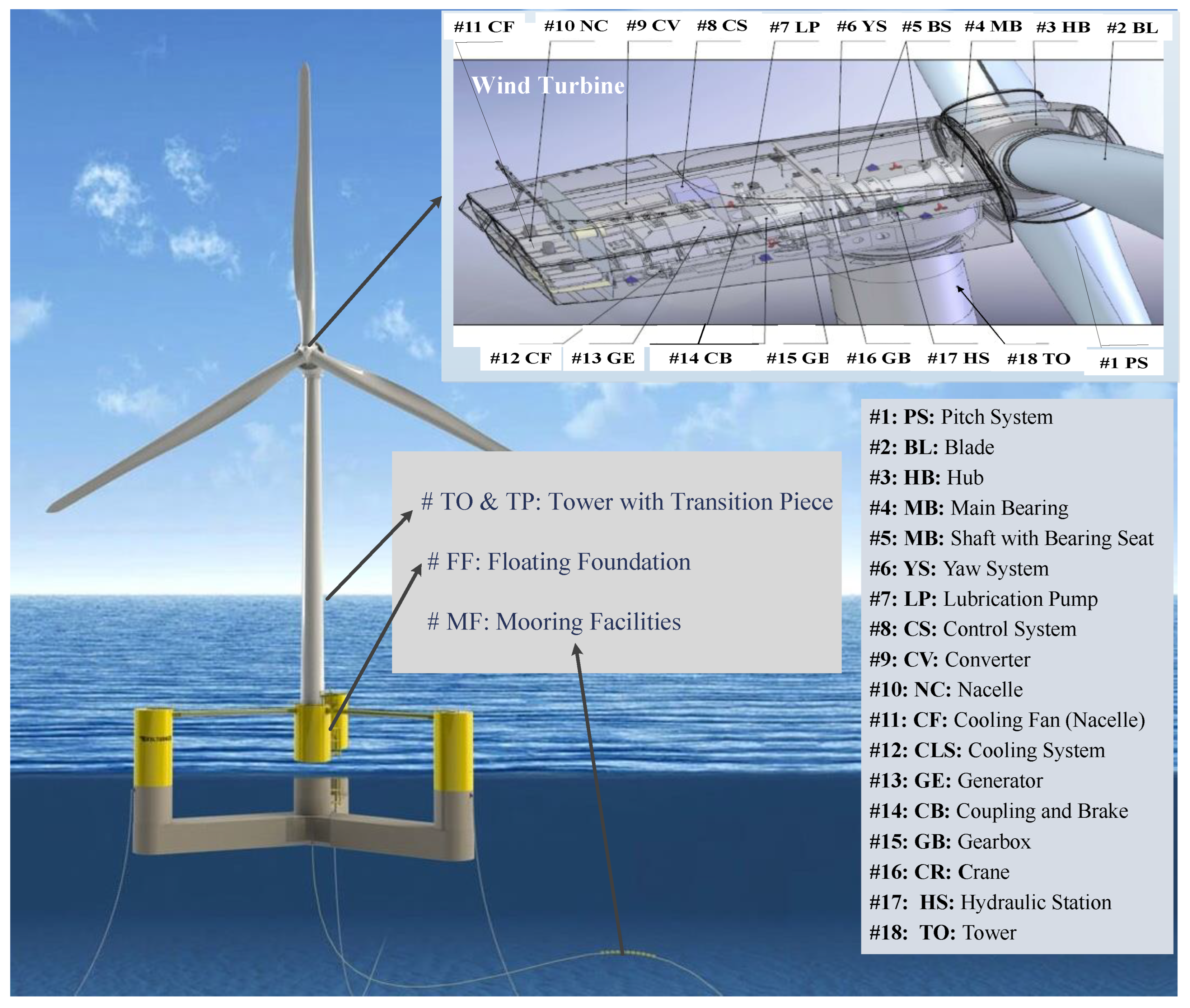
A conceptual model of a floating offshore wind turbine with 5 systems and 15 components is constructed according to publications available, see
Table 1 and
Figure 1.
The energy-receiving system consists of three blades and a hub that converts wind energy into the torque of the main shaft. The energy-producing system is composed of the main bearing, the main shaft, a generator, and a gearbox, which transform the mechanical energy of the main shaft into electricity. The energy-transforming system is designed for voltage regulation and includes a converter and a transformer. The support structure is made up of mooring facilities, a tower, a floating foundation, and a transition piece, which is assembled to support the upper wind turbine. The auxiliary system, which includes a pitch subsystem, a yaw subsystem, as well as several controllers and electrical facilities, guarantees the energy generation efficiency of the floating offshore wind turbine.
- (2)
Selection of failure modes and their corresponding causes
Three designers from two wind energy companies, and one researcher who has worked on failure and risk analysis of floating offshore wind turbines for several years and has several publications on the topic were employed to complete the tasks in this section, see
Table 2. Specifically, three designers with master’s degrees have worked with floating offshore wind turbines for three to four years. Before this, they had more experience and extended working periods on bottom-fixed offshore wind turbines; the researcher with a doctorate has the longest working time on the failure and risk analysis of floating offshore wind turbines compared with designers. The consultation of the specialists was conducted in two continuous rounds: failure items selection, as well as values of severity, occurrence, and detection design. The former was put forward to ascertain potential failure modes and failure causes of the floating offshore wind turbine. The second round of consultation is to obtain information for RPNs calculation.
Round 1: Failure modes and failure causes identification
In the initial round of consultation, a list of 29 failure modes with 53 failure causes taken from publications was distributed to each specialist, who was suggested to delete unlikely failure items and simultaneously add new failure modes (with corresponding failure causes) or new failure causes to existing failure modes. Subsequently, a new failure item is added to the final list if one specialist suggests it, or is deleted if recommended by more than two specialists. Ultimately, 42 failure modes corresponding to 104 failure causes of floating offshore wind turbines were identified, see
Appendix A.
Round 2: Design values of severity, occurrence, and detection
The second round aims to attribute values of severity, occurrence, and detection of failure items that were identified in the previous round. Two documents were distributed to specialists: a final list of failure modes and failure causes (
Appendix A) as well as a rating guidance for the severity of failure modes together with the occurrence and detection of failure causes. The rating guidance provides the specialists with a standard to normalize their knowledge about failures of floating offshore wind turbines, see
Table 3.
- (3)
RPNs calculation
The
RPN is a unidimensional index, without physical meaning, used to rank and assess failure modes. A failure item with a higher
RPN is more critical than those with lower RPNs. However, RPNs are criticized for drawbacks in their implementation in actual engineering cases [
16,
19,
31,
32], for instance: (i) Various combinations of severity, occurrence, and detection may result in the same RPN, and the hidden meaning of each could be completely different; (ii) Indices (like severity, occurrence, and detection) and employed specialists are treated equally when calculating PPNs, in other words, the importance of the indices and the differences of specialists are ignored.
Aiming at removing the aforementioned restrictions, a new way of constructing RPNs is proposed in this study. The experts are weighted based on years of experience, which is an objective and explainable parameter. Other subjective dimensions like educational level (doctor, master) and professional activity (system designer, component designer, quality engineer, researcher) can also be considered in weighing experts, like in Refs. [
41,
42]. However, these dimensions are subjective, and no evidence shows that a specialist with a doctorate is more reliable than others with master’s degrees or industrial specialists who may have better knowledge of failures of floating offshore wind turbines. Introducing such dimensions to weigh experts would bring additional uncertainties and make the results debatable. In this regard, this paper takes individuals’ years of experience as the basis to weigh the experts, considering that years of experience can directly reflect the reliability of knowledge and experience on the failures of floating offshore wind turbines.
The weighted values of indices e.g., severity, occurrence, and detection of FMEA can be computed as:
where,
represents the weighted value of severity, occurrence, or detection of failure cause
j of
i th failure mode of the floating offshore wind turbine. The variable
reflects the original values of FMEA indices given by specialist
k and
denotes the weight of specialist
k which is defined as:
where,
is the working period of specialist
k, see
Table 2.
Hence, the
RPN for failure cause
j of the failure mode
i of the floating offshore wind turbine (
) can be determined by:
Subsequently, the
RPN of failure mode
i (
) is defined as the summation of the RPNs of all its failure causes, which can be represented by:
Accordingly, RPNs for component
h (
) and system
g (
) can be obtained by:
The weighted values of severity, occurrence, or detection of failure causes of the offshore wind turbine together with RPNs calculated (and their ranking) are listed in
Appendix B.
- (4)
Recommendations
The failure analysis of floating offshore wind turbines aims at answering the following questions:
- (1)
What are the key failure items that contribute most to the global failure risk of floating offshore wind turbines?
- (2)
What are the effects, behavior, and root causes of each key failure item?
- (3)
What measures can be implemented to prevent the occurrence of key failures?
Hence, the inherent features of floating offshore wind turbine failures are expected to be explored. Accordingly, recommendations associated with reliable designs and activities related to maintenance and operations are suggested by the specialists employed after they are delivered by the critical failures and their root causes. These recommendations are to guarantee economic benefits and efficient electricity yielding of floating offshore wind turbines by avoiding critical failures. These recommendations are discussed in
Section 3.6.
3. Results
This paper aims to demonstrate the failure features of floating offshore wind turbines, and to suggest potential measures to improve the performance of the system. The measures provide procedures to prevent floating offshore wind turbines from unexpectedly catastrophic failures.
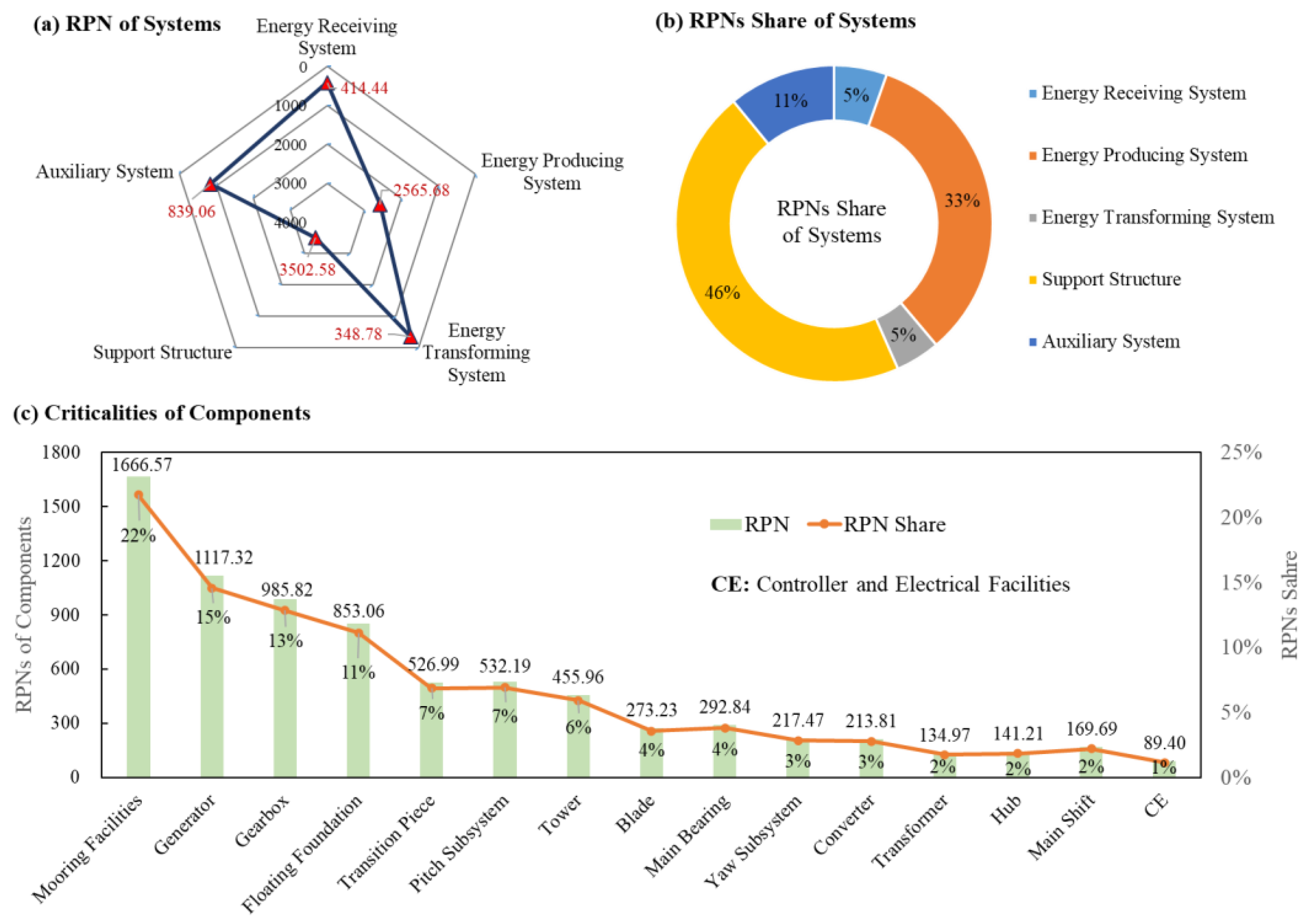
The support structure is the most critical system, as it contributes some 46% of the RPNs of the system, which is significantly higher than that of systems installed within nacelles such as the energy-producing system (33%), auxiliary system (11%), energy-receiving system (5%), and energy-transforming system (5%), see
Figure 2a,b. Floating assemblies are key elements of floating offshore wind turbines over onshore structures. Furthermore, floating assemblies incur considerable risk to the floating offshore wind turbines. This is also confirmed by the relative higher criticalities of components assembled in support structures, that are, mooring facilities (NO.1, with an
RPN share of 22%), floating foundation (NO. 4, 11%), transition pieces (NO. 5, 7%), and tower (NO. 7, 6%), see
Figure 2c.
The results show that the support structure and the energy-producing system have the largest shares of RPNs of the floating offshore wind turbine, which is in line with the knowledge of the specialists who have put greater emphasis on such systems. Specifically, more than 50% of the components, nearly 60% of failure modes, and over 77% of failure causes of the floating offshore wind turbine (collected by this study) are related to the two aforementioned systems.
Figure 2 also demonstrates that: (i) systems with more components, or components having diverse failure modes and failure causes, tend to be distributed by larger RPNs; (ii) systems or components with more complex structures and functions, or subject to inclement working conditions are risk-prone parts of the floating offshore wind turbine.
3.1. Energy-Receiving System
The energy-receiving system collects kinetic energy from the wind and transforms it into the mechanical energy of the main shaft by rotating blades and the hub. The energy-receiving system accomplishes the first step of energy production of the floating offshore wind turbine, that is, from kinetic energy to mechanical energy. One distinguishing property of this system is its particularly huge size, especially the large-scale blades.
Blades are the weak links of floating offshore wind turbines when such facilities enter the seas. Designers are devoted to guaranteeing the survival of these huge structures from irregular wind stress. Two catastrophic failures potentially lead to the floating offshore wind turbine shut down, which are, cracks (RPN = 126) and delamination (RPN = 89) of the blades. The mentioned failures call for the special attention of designers and maintenance teams. A blade crack is a consequence of defective manufacturing, while the blade delamination is due primarily to insufficient lightning protection. Failure of the hub is infrequent. However, manufacturing and fitting errors (RPN = 88) should be avoided to reduce severe consequences, such as blades breaking away from the hub.
3.2. Energy-Producing System
Energy producing system is the most complex system in terms of structure, function, and technological demand. The system is responsible for the second step of electricity generation, which is transforming mechanical energy into electricity. Specifically, the main bearing and main shaft transform mechanical energy from the energy-receiving system to the gearbox. The gearbox converts the received movement into low torque and high-angular velocity rotations. The generator is an electromechanical system designed to transform the rotational motion of the gearbox into electricity by the electromagnetic induction principle.
The generator is more important than other components of the energy-producing system. Both mechanical and electrical components failures can be discovered. Mechanical failures are more severe, while electrical components fail more frequently. To be more specific, bearings failures leading to a lack of, abnormal, or unbalanced electricity generation, and are more critical than the other components of the generator. Root causes of bearings failures can be attributed to electric corrosion of rollaway nests, improper grease, and over-tightening. Moreover, overheating of the generator is a typical failure most likely caused by cooling system failures.
The main reasons for gearbox malfunction are the failures of gears and bearings. Gearbox failures are typical common cause failures since most of them can be associated with lubrication failures. The common cause failures are an explanation for the chain failure form of the gearbox (a slight failure can lead to disastrous failures of other elements) and its severe consequences. Worn gears, fractured gear teeth, and overheating of the gearbox are critical failure modes that lead to vibration and shutdown of the floating offshore wind turbine. Wear, fatigue and lubrication failures are the causes of gearbox failures.
Failures of the main bearings are more critical than those of the main shaft. Common failure modes of these components are abnormal vibration, and cracks resulting primarily from wear, fatigue, substandard lubrication, and welding defects. Details on the failure features of the energy-producing system are presented in
Figure 3.
3.3. Energy-Transforming System
The energy-transforming system is a combination of electrical components including a converter, transformer, cable (mainly among wind turbines, distribution stations, and the grid), power distribution stations, and other support equipment for power transmission from the generator to the shore. The energy transforming system is responsible for adjusting unstable and low voltage electricity generated by the generator into stable and required voltage electricity of the grid. Converters and transformers are considered in this analysis, since they are installed within wind turbines, and other items like power distribution stations and cables, which are not parts of floating offshore wind turbines, are neglected.
Open and short circuits are distinguished failures of the converter and transformer. Failures of the converter are more critical than failures of the transformer. Open circuits result in a disconnection between the generator and the grid. Short circuits, the main reason for fires, lead to the direct shutdown of the converter and the transformer.
Short circuits of the converter and the transformer are consequences of overheating. The root reasons for open circuits of the converter and the transformer are much more complex. The converter’s open circuits are more critical than the same failures of the transformer. On one hand, the primary origins of converter open circuits are cooling system failure and load mutation, which can be compared with those of the transformer: iron core corrosion, overcurrent, and over-voltage. On the other hand, under comparable levels of severity of consequences and likelihood of occurrence, the occurrence of open circuits of the converter is much more difficult to be detected in advance.
3.4. Auxiliary System
The auxiliary system consists of a pitch system, a yaw system, as well as a controller and electrical facilities. This system is not directly involved in electricity production. Instead, it is designed to improve energy production efficiency to guarantee the economy of the floating offshore wind turbine. Pitch and yaw systems adjust blades and the wind turbine to maintain appropriate angles to the wind. Controller and electrical facilities are the “brain” of the floating offshore wind turbine. These systems connect and control several systems and components of the floating offshore wind turbine.
Failures of the pitch system are more critical than those of the yaw system, as well as the controller and electrical facilities. Particularly, the criticality of failures of the pitch system can be attributed to their disaster-causing causes e.g., poor calibration of the pitch angle, wear, fatigue, and the excessive vibration of pitch bearings. Yaw system failures, such as seizure bearings as well as bearing and gear corrosion, are caused by hydraulic system failures e.g., the poor lubrication and wear (or degradation) of hydraulic lines. Failures of the controller and electrical facilities are not critical. These failures can be easily discovered. Failure consequences of the controller and electrical facilities are minor, but these failures are likely to happen frequently. To date, failure warning and detection modules have already been embedded into wind turbine monitoring software, which confirms that the criticality of the controller and electrical facilities failures will further decline.
3.5. Support Structure
Various types of support structures of floating offshore wind turbines, e.g., spar-buoy, semi-submersible, and tension-leg platforms, have been developed to enable offshore wind turbine installations in deep water where bottom-fixed systems are no longer feasible [
43]. Except for the larger size and higher reliability requirements for each component, the main difference between floating and bottom-fixed offshore wind turbines is the employed support structure. Support structures are the most failure-prone part of the system due to their destructive damage and unexpected vulnerabilities raised by harsh sea conditions.
In this failure analysis, the authors and the specialists have particularly focused on the support structure by expecting that this analysis will provide details and insights into the failure features of this relatively new system to the designers and operators of floating offshore wind farms.
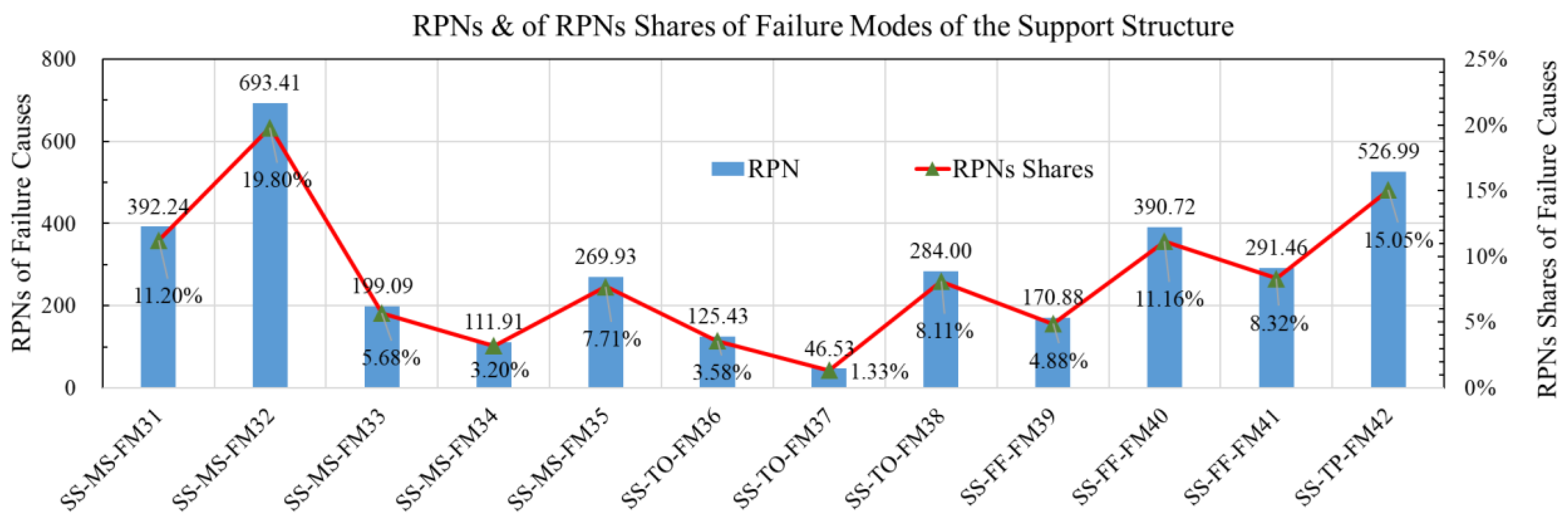
Support structures are designed to sustain wind turbines located at the required height above the sea so that they can access the desired wind resources. Mooring facilities, towers, floating foundations, and transition pieces are typical items of the support structure. The mooring facilities keep the floating offshore wind turbine at the selected location with anchors and mooring lines. The floating foundation provides indispensable buoyancy to the massive upper structures. The transition piece connects the floating foundation and the tower. The tower determines the height of the floating offshore wind turbine. Failure features of the support structure at the failure mode level are listed in
Figure 4.
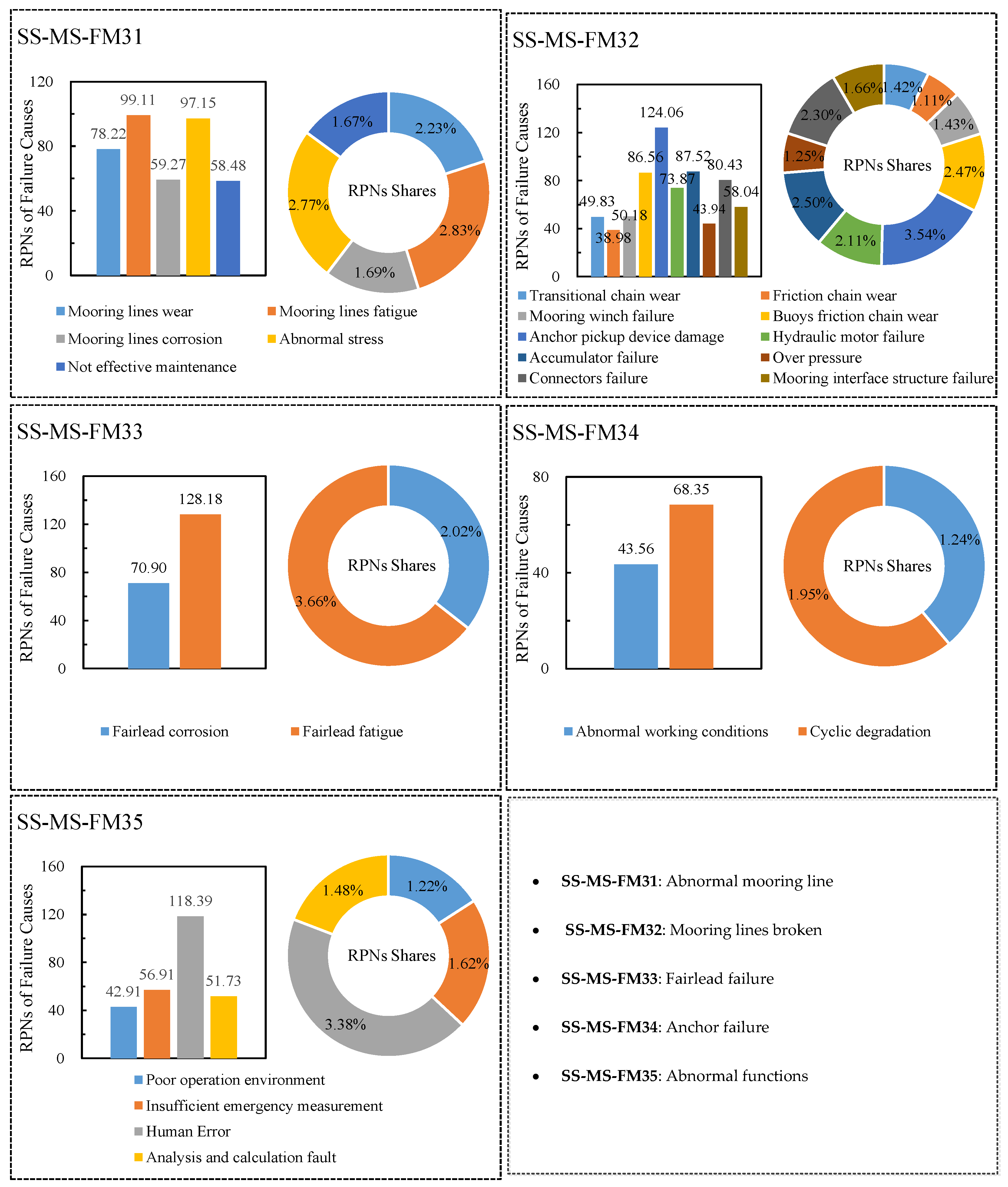
The mooring facilities are much more critical than other components. Mooring line failure is highlighted by its considerably high
RPN (
RPN = 693.41, 9% of the total). Mooring line failure is harmful to the stability of the support structure and the wind turbine. Devices, such as anchor pickup devices, accumulators, and connectors, that failed to accomplish their functions are responsible more often than other degenerative root causes (e.g., wear of the transitional chain and friction chain). An abnormal mooring line is an initial failure mode of the mooring facilities, such as mooring lines breaking. It is a consequence of mooring line wear, fatigue, and unknown abnormal stress. Moreover, several human failures e.g., insufficient emergency measurement and calculation faults, are not neglectable as failures of the mooring lines. Fairlead and anchor failures are not critical. The details of the failure features of the mooring system are demonstrated in
Figure 5.
Regarding tower failures, tower crack is recognized to be critical. Specifically, tower cracks result from faulty welding or material fatigue. Other failures are either merely not possible e.g., tower collapse, or are easy-to-be detected e.g., abnormal vibration. Transition piece failures mainly associated with cracks have not been reported in previous publications. The criticalities of failure causes such as material fatigue, corrosion, plastic deformation of structures, cyclic degradation, strong wind or waves, and faulty welding are considerably high. Details on the failure features of the tower and the transition piece are illustrated in
Figure 6.
The huge volume, massive weight, and inclement sea conditions introduce considerable vulnerability to the floating foundation, particularly to its underwater seals. Virtually, all seal failures result from pipe joint defects such as welding defects, corrosion, and fatigue. The floating foundation is a complex system assembled by multiple devices. Devices’ failures of the floating foundation are diverse, but with low criticalities. Sensors (for platform monitoring), manholes, pumps, and towing brackets are fragile and fail frequently. Dropped objects may result in unexpected and unforeseen damages to the floating foundation and contribute to vast economic losses. This failure is the consequence of harsh and uncertain sea conditions e.g., strong wind/waves, operational failures e.g., plane crashes, or unpredictable events e.g., bird collisions. The details of the failure features of the floating foundation are demonstrated in
Figure 7.
3.6. Recommendations
Failure analysis enables the analysts to comprehensively understand the failure characteristics of the components of floating offshore wind turbines and provide the basis for preventing critical failures from occurring. The conducted analysis includes the development of recommendations to designers and operators (particularly in the maintenance sector) to update designs and optimize maintenance strategies. Accordingly, better economic performance is expected to be achieved by such recommendations formulated as follows:
- (1)
Energy-Receiving System
Improve manufacturing processes and enhance testing in advance of blades being delivered to wind farms; Enhance lightning prevention by designing more reliable and less vulnerable systems for blades; Improve manufacturing and installation processes, especially for connection parts between hubs and blades.
- (2)
Energy-Producing System
Strengthen surfaces of bearing tracks (inner ring, outer ring, and rolling elements) of main bearings; Pay attention to main shaft welding and conduct more strict welding quality inspections; Improve electric corrosion prevention of generators; Upgrade cooling systems to enhance the heat dissipation of generators; Introduce wear and fatigue prevention actions to the gears in gearboxes; Guarantee high-quality lubrication by periodical lubrication inspection and replacement.
- (3)
Energy-Transforming System
Guarantee reliable operation of the cooling system to avoid overheating of converters and transformers; Implement additional design activities for instantaneous voltage or current overload offsetting of converters and transformers.
- (4)
Auxiliary System
Develop control-and-feedback module to monitoring software of wind turbines to precisely adjust pitch angles; Better design of the hydraulic systems, particularly its embranchments of yaw and pitch systems.
- (5)
Support Structure
Enhance the strength of mooring lines to eliminate abnormal stress; Improve the reliability of anchor pickup device, transitional chain, mooring winch, fairlead, and accumulators in mooring systems; Improve the training of operators and maintenance members to avoid human failures; Reinforce tower welding quality; Enhance pipe joint design and welding quality of floating foundations to avoid watertight fault; Improve the sensors of platform monitoring and pay more attention to manholes failures; Implement measures to avoid transition pieces from corrosion, fatigue, and life cycle degradation; Consider the impacts of strong wind/waves in the full life cycle of support structures.
4. Comparisons
This study has collected the knowledge of four experts to complete a failure analysis of a floating offshore wind turbine. This approach takes the specialists’ working experience as weights of their knowledge rather than a traditional analysis that treats values of severity, occurrence, and detection from each specialist as nondistinctive.
A comparative analysis between the ranks of failures obtained by the proposed method and by the conventional model, based on a single expert, was conducted, see
Appendix C. The results show that: (i) rankings of failures based on a single expert are inconsistent with the results of this paper that includes four experts for group decision-making; (ii) the years of the experts’ experience affect the failures’ ranking. To be specific, the overall failure ranking difference between expert #4 (with 6 years of working experience) and the results of the group decision-making in the paper is the smallest, followed by expert #1 (4 years), expert #3 (4 years), and expert #2 (3 years); (iii) two experts with the same working period show some 40% difference in their ranking of failures, which indicates that individual properties of experts impact their judgments.
A comparative analysis was also carried out to show the rank differences between the conventional and the proposed FMEA methods based on the group of 4 experts, see
Figure 8, where failure items with the same
RPN of both FMEAs are not displayed. The figure reveals that: (i) the proposed FMEA reclassifies most failure causes of the floating offshore wind turbine. To be specific, 89 of 104 failure cause ranks were changed, since this analysis distributed higher priorities to experienced specialists and decreased the credibility of specialists who have short working periods in the field; (ii) the
RPN ranks of failure modes changed slightly, and failure modes with fewer root causes change more distinctly than those with more causes; (iii) Experienced specialists consider pitch system failures to be more critical; (iv) RPNs of systems of the floating offshore wind turbine calculated by the proposed FMEA are superior to that of the conventional FMEA technique. It reflects that experienced specialists tend to provide more aggressive evaluations than the others; (v) The use of more specialists for failure analysis, and simultaneously the prioritization of their knowledge according to their experience, is in line with practice and can provide convincing results.
Overall, this paper identifies possible failures of floating offshore wind turbines, and identifies the most critical failures and their causes from a risk management point of view by considering the influence of the experts’ backgrounds. In addition, actions to prevent the occurrence of the root causes of critical failures are determined.
Although the recommendations for failure prevention summarized in this paper are applicable, additional ranking criteria can also be considered. Economic factors, like failure cost, and operational factors, like downtime, may also be used as criteria for ranking the criticality of failures from other perspectives. The joint consideration of various criteria will contribute to more robust conclusions.


