1. Introduction
Autonomous underwater vehicles (AUVs) have a wide range of applications in military and civilian operations, such as resource exploration and enemy reconnaissance. Traditional AUVs mostly use blade propellers as actuators, which can obtain greater thrust force and higher speed while baring many problems, such as low efficiency, high energy consumption, high noise, etc. To make up for these shortcomings, researchers found inspiration from aquatic creatures, especially fish, and developed various underwater robots based on the principle of bionic propulsion.
The propulsion modes of fish can be divided into two main types: median-paired fin (MPF) and body-caudal fin (BCF) propulsion [
1], each with its own advantages, although it is difficult to achieve an optimal combination of speed, acceleration and maneuverability at the same time [
2,
3]. Fish that use MPF propulsion mode gain advantages over those that use BCF in propulsion efficiency, maneuverability and noise control [
4,
5]. Myliobatidae creatures, such as manta rays and cownose rays, have large, flat body features that offer more carrier space and payload than fusiform fish (mostly BCF propulsion), and their wide, delta-shaped pectoral fins can achieve vectorial propulsion, simultaneously functioning as the main thrust generator and controlling rudder. The pectoral fin movement of rays can be regarded as a combination of span-wise flapping and chord-wise pitching, which is driven and conducted by the muscles and cartilages of the highly flexible fin organism [
6,
7].
The complex locomotion and control freedom of the pectoral fins, plus the relatively better payload capacity of ray-like fish, has drawn attention from many researchers in the field of bionic underwater robots. Much research has been conducted on ray-inspired bionic robot fish; however, due to the limitation of actuators, structural volume/weight, control complexity and other factors, the existing prototypes and their bionic pectoral fins were either oversimplified, thus unable to reproduce the flexible characteristics of the original creature, or pursuing full flexibility or a new actuating method came at the expense of swimming performance and payload capacity.
For example, early prototypes used a flexible rod as finray in the leading edge, with a soft membrane connected to it as the fin surface [
8,
9,
10,
11]. These two-dimensional fins driven by motors or smart actuators, such as SMAs, can only perform the span-wise flapping motion and have to rely on the passive deformation of the soft membrane to swim forward, which leads to poor maneuverability because they cannot control the direction of thrust force. Some researchers used more flexible rods driven by several motors to build multi-DOF fins and achieved better maneuverability [
12,
13,
14,
15,
16]. Although their flexible skin can preserve the 3D shape of the pectoral fin, the rigidity of the inner skeleton and outer skin differs so greatly that these materials cannot match well under movement, leading to lower swimming speed. Later on, 3D soft fins made of solid rubber instead of hollow skin were developed [
17,
18]. Such a structure can better preserve the fin profile during motion but may also lead to low energy efficiency because it requires much higher torque for inner skeletons to move in solid materials, especially for multi-DOF fins. Although this problem can be avoided by setting only one bending skeleton at the leading edge, it requires compromises in maneuverability, like earlier prototypes.
Most of the above research has mainly focused on one type of pectoral fin that only performed well either from a pure speed or maneuverability point of view, and rarely has the performance of different fin structure types been compared on the same platform to find an optimal solution. There are some remarkable studies on underwater bionic soft robots, such as fish [
19] and frogs [
20], as well as biological comparison research on the pectoral fins of different dolphin populations [
21], all offering valuable information for the design, fabrication and experimentation of a new soft bionic pectoral fin. In this paper, a ray-inspired robot fish with both three-dimensional biomimetic shape (higher speed) and multi-DOF pectoral fins (better maneuverability) is presented. In
Section 2, kinematic model of the pectoral fin based on motion analysis of cownose rays is introduced as guidance for the design of a bionic propelling mechanism. Then, a high-fidelity parametric geo-model of the fish is established based on statistical data observed from natural specimens, and the mechanical structure and control system of the robot fish is presented, as well as the manufacturing process of the bionic pectoral fins. In
Section 3, a comparative experiment is carried out, and the forward swimming and steering speed of the robot ray with two different fin types are recorded. Results are discussed to further investigate the influence of different fin structures and materials on swimming performance of the robot fish. Finally, conclusions and future work are listed in
Section 4.
2. Materials and Methods
2.1. Kinematic Model
Morphology, kinematics, structure and function are essential elements of a bionic robot ray, similar to all other biomimetic robots. Rhinoptera bonasus, also known as cownose ray, is characterized by its streamlined flat body and delta-shaped pectoral fins with high aspect ratio. The flat body located in the middle is a rather rigid part, and the delta-shaped pectoral fins on either side are constructed with highly flexible organisms as a radial cartilage network in the middle, with muscles connected to it on the upper and lower sides. Previous research [
7,
22,
23,
24] provides guidance on geometric design and material composition in prototype development. Kinematic observation and modeling play a more important role, directly determining the swimming performance of the robot ray.
The locomotion of the cownose ray can be categorized as MPF oscillation mode when the span-wise and chord-wise wave numbers on the pectoral fin are less than 0.5 [
6]. Under these circumstances, it can be seen as a combination of span-wise flapping and chord-wise pitching. On one hand, the basal part of the fin first flaps upwards or downwards, and then the distal part is dragged to move after it, forming a parabolic curvature with a small phase delay from fin root to tip; on the other hand, the flexible deformation of the fin under hydro-force forms a pitching motion, along with an incremental angle of attack from fin root to tip.
In our previous research [
25], motion frame sequences of the cownose ray were extracted from steady swimming videos taken from different aspects in an aquarium (side view and lateral view). Essential locomotion parameters, such as flapping amplitude, frequency, pithing angle and phase difference, were extracted by analyzing these frames using a Matlab verge-point capture script. The coordinate system of the pectoral fin was then established for kinematic modeling.
The coordinate system of the pectoral fin was established as shown in
Figure 1a. The origin point was set at the root of the fin leading edge. Axis
y is parallel with the middle body axis and points backward, axis
x is perpendicular to it and axis
z is determined by the right-hand rule. Based on the cartilage distribution feature of the pectoral fin [
24], a bionic cartilage system was established to better describe different locations on the fin surface. As shown in
Figure 1b, the pectoral fin was discretized chord-wise into a group of parallel finrays at an amount of
m and span-wise into a group of segments connected by a series of joints, the max number of which is
n along the longest finray.
For an arbitrary segment, it rotates around the previous joint at a certain angular velocity, and there is also a time delay between the neighboring finrays. Define
S as the normal distance from joint
n to axis
y, which also represents the maximum fin span; then,
S =
nsj if every fin segment is of equal length. By increasing the degree of discretization, i.e., the number of
m and
n, nearly every point on the pectoral fin can be described by the kinematic model as follows:
where
θij is the flapping angle of segment
sj on finray
I;
βj is the pitching angle of the chord line,
Cj;
ψ1 and
ψ2 are the phase differences of
θij and
βj, respectively, between the neighboring segments. According to motion analysis of swimming video frame sequences, the maximum flapping amplitude,
θmax, and pitching angle,
βmax, are about 60° and 30°, respectively. Moreover, the flapping and pitching frequency,
f1 and
f2, is in the range of about 0.3–0.5 Hz, and there is also a 90° phase delay between
ψ1 and
ψ2. The key parameters and three calculated motion trajectories of different fin locations (points along the longest finray from root to tip) are illustrated in
Figure 1d, providing fundamental principles for the bionic fin design.
2.2. High-Fidelity Geometric Model
The streamlined flat body and flexible delta-shaped pectoral fins that evolved over millions of years are important factors allowing the cownose ray to swim with high speed and low drag. Although most of the researchers have mainly focused on the design of the bionic fin mechanism during robot development, few have paid attention to the biofidelity of the geometric model. For most existing prototypes [
9,
10,
11,
12,
13,
14], only an approximate outline of a “ray-like” body shape was adopted, of which key geometric parameters were defined according to subjective observation rather than objective measurement. Later research managed to CT-scan a natural specimen of a cownose ray to acquire a more realistic geometry [
18]. It is a very inspiring work, but it was based on a single specimen, and unfortunately, the scanned data were not openly shared. To the best of our knowledge, there is no common standard to evaluate the precision of modeling. To better meet the morphology principle of bionic robots, a high-fidelity geometric model of a cownose ray was established based on statistical data, and a precision evaluation method was proposed to parametrically assess our model as an attempt to set a possible standard for related research.
Based on statistical morphology data of more than 10 specimens of Rhinoptera bonasus and Aetobatus narinari (highly similar in body shape and locomotion mode) [
25], key geometric parameters were extracted and combined with fin foil data from the NACA airfoil database [
26] to determine the profile of each section, and the photo projection of the fish was also referenced during data integration. The 2D fin profile was then calculated by the licensed airfoil design software Profili 2 and imported into SolidWorks to build the 3D surface using multi-section lofting and multi-spline controlling methods. Specifically, a combination of NACA63-20, 63-18, 0015 and 0012 profiles was merged to generate a geometric model that better matches the original bionic object, as shown in
Figure 2.
Additionally, careful evaluation was carried out to make sure the model was of high fidelity both statistically and geometrically. As shown in
Figure 3, typical parameters that have a major influence on fin geometry were compared. Fin thickness,
T, is measured span-wisely from the middle plane of the body to the tip of the fin, and shoulder length,
S, is the distance from the leading edge to the max thickness point.
T/C and
S/C are the ratio of
T and
S, respectively, divided by the chord length,
C. They are important indicators of the maximum thickness and its location in different sections of the fish. Results show that in the medial-to-distal part of the fish, integrated parameters of the geo-model align well with statistical data from [
25] and the profile data calculated based on the NACA database [
26]. In the basal part, the integrated parameters are also well balanced between statistics and calculation. The average error of
T/C and
S/C is less than 2%, indicating the high precision of our parametric geo-model.
Moreover, the zebra stripes and curvature check illustrated in
Figure 3c show good surface quality and continuity, ensuring high smoothness and low drag coefficient. The photo of a living specimen in
Figure 3d was used to check the outline similarity from a vertical perspective. This rigorously assessed model will be used as the basis reference in the following structural design of a robot fish prototype and its bionic pectoral fins.
2.3. Multi-DOF Bionic Propelling Mechanism
According to the kinematic model presented in the previous section, pectoral fin locomotion can be decoupled into two independent motions: span-wise flapping and chord-wise pitching. Meanwhile, anatomical results show that muscles are stronger and thicker at the basal part of the fin, whereas the distal part consists of more flexible cartilage [
7,
24], which implies that the basal part contributes more to the actuation power output, whereas the distal part mainly focuses on fin surface deformation control. Based on these features, a novel bionic propelling mechanism with multiple degrees of freedom that can mimic the fin locomotion pattern was developed.
As shown in
Figure 4, the scheme of this mechanism contains 4 structural components and 5 kinetic pairs. Front link 1 and rear link 4 are driven by two motors, which are defined as revolute pair I and V, respectively. Front link 1 and fin base 2 are also connected by revolute pair II, whereas rear link 4 connects to fin base 2 through a combination of spherical plus cylindrical pair III and sliding pair IV. A combination of two sliding rods and one spherical hinge is compactly integrated by component 3, which plays a fundamental role in achieving the flapping and pitching composite locomotion of fin base 2.
This novel parallel mechanism can simultaneously realize the spatial movement of flapping and pitching and control them independently. In addition to the two basic degrees of freedom of fin base 2, optional accessories can be easily added to introduce extra degrees of freedom and better control of fin surface curvature in the distal part. Thanks to the abundant space and mechanical interface on the fin base, bionic fins can be conveniently installed or replaced, making comparative study of modularized fin units with various types of structure possible.
2.4. Fabrication of Bionic Pectoral Fins
For the comparative experiment presented in
Section 3.1, two different kinds of bionic pectoral fins were fabricated. Both were formed in 3D shapes according to the geometric model presented in
Section 2.2.
The first kind was constructed with a flexible skeleton, soft ribs and a permeable outer skin, as shown in
Figure 5a,b. The skeleton frame was first cut from carbon fiber boards of 0.6 mm and 1.2 mm and then bonded together with a “thin–thick–thin” sandwich structure to mimic the stiffness distribution of the original pectoral fins, which changes from more rigid at the fin base and leading edge to more flexible at the fin tip and the trailing edge. The soft ribs function as chord-wise support to maintain the streamlined profile of the fin. They were made of silicon rubber made by mixing two liquid ingredients and then pouring them into a premade mold to solidify. The outer skin makes direct contact with water, and hydro-force is generated on it through this interaction. The outer skin was made of polyurethane cloth, which is permeable with good flexibility in order to cover the skeleton and ribs tightly and form a 3D fin surface without wrinkles. A servo was also installed on the fin base and connected to the middle beam of the skeleton in order to better control the pitching angle in the distal part of the fin. Our multi-layer skeleton that varies in thickness can better mimic the stiffness distribution of the original pectoral fin, which differs from traditional fin structures used in previous research [
12,
13,
14,
15,
16]. Based on this new fabrication method, an upgrade of soft rubber fins was made, which refers to our second kind of fins.
The skeleton layout and sandwich structure were similar to the those of the first fin type, except that the thickness of the carbon fiber boards was reduced to 0.5 mm and 0.8 mm because the solid rubber fins already had a basic stiffness level higher than that of the skin structure. Bio-inspired by the connective tissue, the smooth skeleton surface was covered with a fluffy fabric layer on both sides so that the the more rigid carbon fiber and the much softer silicon rubber would tightly bind together, as shown in
Figure 5c. The multi-layer skeleton was then placed into a 3D-printed mold and filled with mixed-liquid silicon rubber with a hardness of Shore 5A after solidification, similar to the flexible tissues of real pectoral fins. A distal-pitching control servo was also installed. The finished bionic soft fin is presented in
Figure 5d.
2.5. Structrual and Electrical Integration of the Modular Prototype
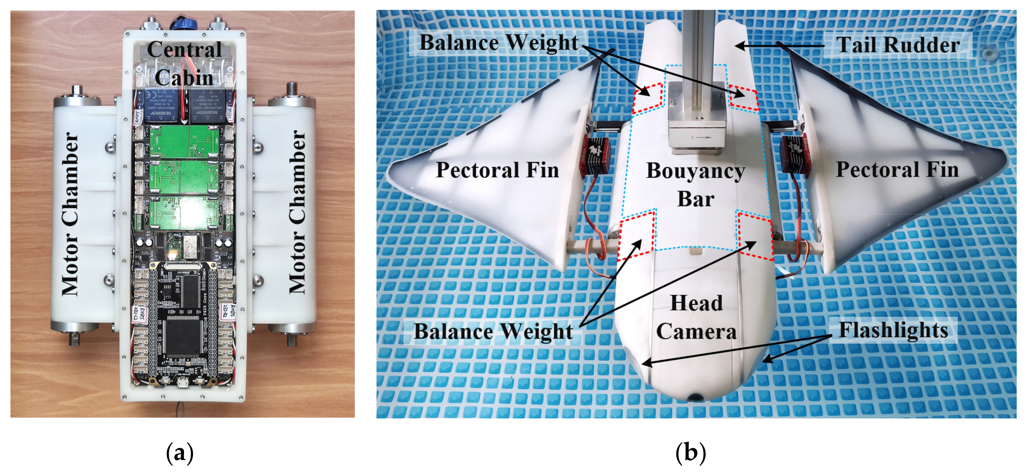
Our robot ray prototype was designed to be a multifunctional platform to carry out different experiments or tasks with various types of payloads. Accordingly, a modular design was introduced from the beginning. The central cabin plays a significant role among all the modules because this small, watertight box contains most of the electronic devices, including four motor drivers, the battery pack and an integrated control board. The motor chambers are also very important because they each contain two high-power density motors (15 Nm peak torque and 75 W max power) in a limited space, similar to two standard servos in volume but 5 times in power. The two motor chambers were connected to the left and right sides of the central cabin, respectively, and all joint surfaces were sealed with rubber rings. These three parts protect the fragile electronic devices to a maximum 20 m depth of water and occupy only 23% of the total volume, concentrating 45% of the fish total mass, making lots of space available for extended-function modules.
Except for the central module (central cabin plus two motor chambers, shown in
Figure 6a), other necessary modules, such as the pectoral fin, the tail rudder, the head with a camera and flashlights/sonars, are all waterproof and therefore able to be quickly assembled with no leakage issues. Furthermore, various extended modules, such as acoustic communication/positioning devices, can be attached using the ample available space. Several 3D-printed hollow buoyancy bars that follow the back and belly curvature of the fish body were mounted on both sides of the central module, and the four corners were loaded with lead weights to balance the extra buoyancy. As shown in
Figure 6b, the final prototype was 0.58 m in body length and 0.89 m in wingspan, similar to the size of a male cownose ray in nature. Due to the difference in water displacement, the total weight of this robot is 6.2 kg with skin–skeleton fins and 8.0 kg with solid rubber fins.
The architecture of electronic hardware is shown in
Figure 7. An STM32F429IGT6 microcontroller was selected as the main processor of the robot ray control system, and various peripheral devices were linked to this powerful chip through different interfaces.
Four motor drivers were used to control four high-power density motors (two on each side) in order to independently actuate the fin-propelling mechanism with close-loop control. The drivers communicate with the MCU through CAN bus and are capable of 1 kHz control/feedback frequency. Eight PWM output interfaces were set to control servos on the tail fin and other extended devices. Two sets of interfaces were used for wireless communication: a 170 MHz RF module for full-duplex serial data transmission and a 35 MHz 8 CH receiver for one-way radio control. The former is more convenient for experiments that require precise motion commands or real-time data feedback, whereas the latter has a longer transmission range underwater and is better for outdoor applications.
Multiple sensors were adopted, including a pressure sensor used to calculate water depth; an IMU module used to measure current motion status, such as body orientation and acceleration; two micro sonars to detect obstacles ahead; a liquid conductive sensor to prevent leaking accidents; and as a voltage/current sensor to monitor system power consumption. Most of these sensors connect to the MCU through an SPI or I2C bus, which are convenient to mount multiple devices, whereas other regularly used interfaces, such as ADC ports, were also reserved for possible extension.
The power supply is a 25.2 V, 6400 mAh lithium battery pack with a current capacity of more than 20A, which allows a 350 W maximum power output. Several on-board DC-DC modules convert battery voltage to 12 V, 7.4 V and 5 V for servos and other extended devices. The power and signal lines (red solid lines and black dashed lines, respectively, in
Figure 7) were also isolated to minimize interference. Furthermore, a motion control program based on the CPG algorithm was developed to ensure smooth and robust locomotion of the robot ray.
3. Results and Discussion
3.1. Experimental Setup
To test the actual performance of the propelling mechanism and soft bionic fins, different swimming experiments were carried out to measure cruising speed, steering speed and radius as important indicators to assess the speed and maneuverability of the robot ray. Parallel experiments on the prototype with “skin-skeleton” structured fins were also conducted as a comparison group.
A cruising test was performed in a swimming pool with dimensions of 4.0 m × 5.5 m × 1.3 m and a water depth of 1.0 m, as shown in
Figure 8a. The prototype was immersed in the water to a depth of 0.5 m and swam straight forward from one side of the pool to the other, with a group of kinematic parameters sent by remote control. The starting line was set at 2.2 m from one side of the pool, with the finish line 0.3 m from the opposite side, creating a 3-meter observation distance in which the robot ray would reach steady cruising speed after pre-acceleration. Two cameras were installed on a steel beam aligned with the cruising route right above the starting and finishing line, respectively, in order to minimize measuring errors caused by the oblique projection effect. Video recording was initiated simultaneously to capture the exact moment when the fish head went across the two lines; then, the average speed could be figured out by calculating the time taken to cover the 3-m distance, and each test with same kinematic parameters was taken performed times to reduce measuring errors.
The turning test took place in the same environment as the cruising test. Differently, the robot ray was placed in the middle of the pool, where the distance from the fin tip to the nearest lateral wall was more than 1.5 m, eliminating interference by reflection wave as much as possible. As shown in
Figure 8b, a COM (center of mass) arrow marker was attached to the fish back, and a similar marker was placed nearby on the pool bottom as a reference point. A camera was set 0.4 m above the water to record HD videos of the turning motion at a framerate of 60 fps. By analyzing the trajectory of the COM marker and the time cost of the arrow rotating 360°, the average steering radius and speed were calculated.
According to the pectoral fin kinematic model and characteristics of the bionic propelling mechanism, locomotion at the fin base can be actively controlled by the rotation angle of the front link,
θ1, and rear link,
θ2, through the sinusoidal function shown below:
where oscillating amplitude,
A, and frequency,
f, of these two links, as well as the phase difference,
φ, between them, are the three key parameters for the motion control program. By altering these parameters in motion commands, different underwater maneuvers can be achieved. For the cruising test, parameters on both sides were the same, generating balanced thrust force to reach high forward swimming speed. However, for the steering test, the phase difference on either side was changed or even reversed to achieve fast steering speed and small turning radius.
To carry out studies on the influence of different motion parameters on robot ray swimming performance, for each test group, only one of the three parameters was changed, and the rest remained constant. Their mapping relationship will be discussed in the next section.
3.2. Cruising Performance Results
The comparative results of the cruising speed achieved with two types of bionic fins under different flapping amplitude, frequency and phase difference are shown in
Figure 9. In the following discussion, the experimental group with soft rubber fins will be referred to as Group 1, whereas the comparison group with skin-skeleton fins will be referred to as Group 2.
The amplitude increased from 10° to 60° with a 5° step length, and the speed of each fin group was recorded at an ordinary frequency of 0.4 Hz and a higher frequency of 0.8 Hz. The phase difference was set to an optimal 40° to achieve maximum speed. According to
Figure 9a, the cruising speed increased approximately linearly with flapping amplitude for both fin groups, although the growth rate of Group 1 was slightly higher. The absolute speed of Group 1 was always higher than Group 2 under the same amplitude, and a top speed of 0.68 m/s (1.17 BL/s) was achieved when A = 60° at 0.8 Hz—approximately 15% faster than Group 2.
The frequency increased from 0 to 1.0 Hz with a 0.1 Hz step length, and the speed was recorded for the two groups at an amplitude of 45° and 60°, respectively. An optimal 40° phase difference was set for both as above. According to
Figure 9b, the cruising speed first grew rapidly with the increase in frequency, and then the growth became flat after 0.6 Hz. The S-shaped curve indicates that the relationship between frequency and cruising speed was nonlinear, so the contribution of frequency to cruising speed was not as steady as that of amplitude. The maximum growth rate of each curve was in the range of about 0.4–0.6 Hz, with frequency increment contributing the most. This might explain the fact that rays in nature usually choose a relatively lower frequency at 0.4 Hz when exhibiting cruising behavior and adjust their speed by changing amplitude. The absolute speed of Group 1 was still higher than that of Group 2 under the same frequency, with the gap increasing as the frequency increased. A curious phenomenon is that the robot ray could not maintain steady forward swimming with simultaneous high amplitude and high frequency, and skin-skeleton fins had better stability performance than that of soft rubber fins under such circumstances. As a result, cruising speed above 45° and 0.8 Hz for Group 1 was not recorded.
The phase difference increased from 0 to 50° with a step of 5 deg, and the speed was respectively for the two groups under 45° of amplitude and 0.4 Hz of frequency as a usual parameter combination for optimal cruising efficiency. According to
Figure 9c, phase difference had less influence on speed than the other two parameters. The speed curve climbed slowly at first, but a rapid increase occurred at about 30°. However, after reaching the maximum at 35° to 40°, the speed dropped a little under larger phase-difference conditions, indicating that there is an optimal value at about 35° to 40 deg that can provide maximum thrust. This might be due to the fact that the pitching angle in the basal part of pectoral fins was just within the proper range to create an optimal angle of attack with a maximum thrust-to-drag ratio, which is approximately 75 (C
l/C
d) at 9° (AoA) for the NACA0012 profile according to the referenced database [
26] and calculation by Profili software. Another interesting phenomenon was observed: the speed of Group 1 dropped below that of Group 2 at first but increased quickly and outpaced that of Group 2 until the end. Additionally, the top speed of Group 1 was reached sooner than that of Group 2, at about 35°.
The above experimental results show that the robot ray with soft bionic fins had higher cruising speed in most cases, indicating superior performance compared to traditional bionic fins with a skin-skeleton structure. A possible explanation is that soft fins can better preserve their streamlined 3D shape both under static and dynamic conditions, whereas the flexible skin is crashed into the ribs under water pressure, jeopardizing the high-lift, low-drag fin profile. The solid rubber can also better interact with hydro forces, whereas permeable skin causes considerable power loss because part of the water passes through the porous fabric instead of transferring more kinetic energy to the fin surface.
However, such features can be an advantage for skin-structured fins under certain conditions. For instance, the energy attenuation during strenuous flapping movements may also create a damping effect to better absorb vibration caused by periodic hydro forces, thus making the robot ray swim more steadily. Meanwhile, skin deforms better than relatively rigid rubber under slight forces and can actually form a larger effective angle of attack when the phase difference is close to zero, thus generating a slightly higher thrust force. The two phenomena that appeared in frequency and phase difference charts could be explained as above.
3.3. Maneuverablility Performance Results
The comparative results of the steering speed and radius achieved with two types of bionic fins under different amplitudes and phase differences are shown in
Figure 10. The frequency was set to 0.4 Hz as a constant, according to the optimal flapping frequency most regularly used by cownose rays in nature. Group numbers defined in previous section are still effective here.
During the first steering test, the amplitude of the right fin was set to zero, and the phase difference of the left side was set to 40°, simulating the steering mode of single-DOF fins by changing the left amplitude only. According to
Figure 10a, as the amplitude increased from 25° to 50°, the steering radius of both groups dropped by about 40% to 1.0 m at nearly the same rate. For amplitudes under 25°, the turning radius was too large for the pool space to cover and was therefore not recorded. For amplitudes over 50°, the prototype encountered stability problems due to the unbalanced rolling torque created by one-side flapping. This steering mode is a compromise strategy used by traditional robot rays with single-DOF membrane fins because they cannot actively control the flapping phase on either side and therefore have to use only one side of the fin to create maximum steering torque.
For the second steering test, the phase difference was set to the same absolute value but opposite on either side. By creating a clockwise steering torque around the COM of the robot, pivot steering (zero in radius) was achieved. The amplitude increased from 10° to 60°, and the steering speed for both groups under a phase difference of 20° and 40°, respectively, was recorded. According to
Figure 10b, the steering speed grew rapidly before the amplitude reached 35°, and then the growth rate dropped but still reached a max speed of 69°/s. Steering speed with a larger phase difference was always higher, indicating that greater steering torque was generated. The difference between the two fin groups was rather small, and both groups performed well relative to previously reported research results, features of which are listed in
Table 1. As can be seen, the body length and span width of our robot ray are relatively larger than most other prototypes, which provides larger in-body volume (extra space) to carry functional equipment, such as aquatic sensors, without jeopardizing the streamlined body shape. Larger pectoral fins provide a more effective propulsion area and achieve faster cruising speeds than prototypes of comparable size and weight [
8,
16]. Meanwhile, this diameter is similar to the body size of a mature male cownose ray and can better mimic the hydrodynamic features of the natural creature without considering the fluid similarity law during experimentation and calculation. However, the relatively larger size also results in greater water displacement and requires more weight to balance the extra buoyancy if no payload is installed. This might be a double-edged sword for swimming performance because higher inertia leads to better stability and poorer maneuverability at the same time during high-speed cruising. More thrust or brake force is needed in order to maintain good acceleration/deceleration performance, which might also lead to higher power consumption. Such a problem not only concerns robot rays with 3D solid rubber fins but also robots with skin-skeleton fins, although their weight seems lower in air because the increased mass should also be counted after the hollow fin structure is filled with water. One solution is to use 2D membrane fins, as they can be both light in weight and tiny in displacement. Such robots often sacrifice payload capacity for better high-speed performance [
10,
11], which is not our intended approach. Another possibility is to develop an intelligent tradeoff strategy to either maximize performance or power efficiency by choosing the optimized motion parameter sets for current working conditions, which requires a large number of hydrodynamic experiments with the robot ray and further study on the thrust generation mechanism of the pectoral fin in the future.
4. Conclusions and Future Work
In this paper, a bio-inspired robot ray with a multi-DOF propelling mechanism and 3D-shaped bio-soft pectoral fins was presented, and a series of swimming experiments were carried out. The parametric geo-model of the robot ray went through different assessments and was proven to be of high fidelity. Under the guidance of the pectoral fin kinematic model, the novel multi-DOF propelling mechanism can simultaneously achieve flapping and pitching motion to mimic the locomotion pattern of the original creature. Thanks to more realistic bionic stiffness distribution and better hydrodynamic profile preservation, our new pectoral fins fabricated with soft silicon rubber achieved much better cruising performance than traditional skin-structured fins and showed a small advantage in maneuverability as well. Experiment results also show that with the increase in flapping amplitude and frequency, both cruising and steering speed increase, although the rate of growth drops at higher intervals, and motion stability is compromised during extreme violent movement, especially for cases with soft rubber fins. Top speed is reached when the phase difference is about 35°~40° but not higher, indicating that there is an optimal combination of the three kinetic parameters to achieve better swimming performance.
Designed with the principle of morphological, kinematic and structural bionics, our robot ray reached a top cruising speed of 0.68 m/s (1.17 BL/s) and a pivot steering speed of 69°/s, achieving the combination of high speed and maneuverability with little compromise.
In the future, this modularized prototype will be used as an experimental platform to carry out further studies on hydrodynamic characteristics of pectoral fins and energy efficiency of propelling with different chord-wise and span-wise flexibility, determining out better optimized solutions for stiffness design, motion control and power management. Autonomous swimming control with a multi-sensor fusion algorithm will also be tested on this platform soon.


