Review

Research Progress on Global Marine Gas Hydrate Resistivity Logging and Electrical Property Experiments

1
Laboratory for Marine Mineral Resources, Pilot National Laboratory for Marine Science and Technology (Qingdao), Qingdao 266237, China
2
Key Laboratory of Gas Hydrate, Ministry of Natural Resources, Qingdao Institute of Marine Geology, Qingdao 266237, China
3
School of Geophysics and Information Technology, China University of Geosciences, Beijing 100083, China
*
Author to whom correspondence should be addressed.
J. Mar. Sci. Eng. 2022, 10(5), 645; https://doi.org/10.3390/jmse10050645
Submission received: 17 March 2022 / Revised: 5 May 2022 / Accepted: 6 May 2022 / Published: 9 May 2022

Abstract

:
Natural gas hydrate is widely spread in marine environments around the world. It has great energy potential due to its high methane gas content. High-precision exploration and evaluation of marine gas hydrate still face great challenges as it is affected by the complex reservoir control mechanisms and distribution characteristics. Resistivity is widely used in geophysical logging and theoretical research on gas hydrate-bearing reservoirs by utilizing the high sensitivity electrical response. In this paper, based on the examination of the global marine gas hydrate occurrences, resistivity logging results are summarized. Then the key remaining gas hydrate resistivity experimental concerns are reviewed. In summary, resistivity properties are a reliable means to derive the gas hydrate reservoir characteristics, despite the effect induced by the anisotropic properties of hydrate reservoirs and drilling technology. The overall resistivity change associated with the occurrence of pore filling gas hydrate in reservoirs are relatively small, and the specific value is affected by sediment lithology and hydrate saturation. On the other hand, fracture filling hydrate reservoirs have strong anisotropy, and massive hydrate occurrences (i.e., layers of gas hydrate with no sediment) section shows very high resistivity variation. Clay minerals are an important factor restricting the accurate estimation of gas hydrate saturations from in situ resistivity measurements. Many experimental studies have proposed the correction of Archie empirical formula, but widely representative models have not yet been developed. It is worth noting that more complex resistivity measurements may be able to provide additional electrical response information on various gas hydrate systems.

1. Introduction

During the natural gas migration from deep within the earth to the surface, the migrating gas can combine with water molecules under certain temperature and pressure conditions to form solid ice-like substances, which are usually called natural gas hydrates [1,2]. Geological survey results show that there is a significant amount of natural gas hydrate in the ocean with water depth of more than 300 m [3,4,5,6], and their main component is methane. It is estimated that the methane gas stored in global gas hydrate is about 1.8 × 10¹⁶~2.1 × 10¹⁶ m3, twice the organic carbon reserves and as much as the sum of coal, oil, and conventional natural gas globally [7,8,9]. Therefore, since the end of last century, an upsurge of gas hydrate resource exploration and development has swept the world. China, the United States, Japan, Canada, Germany, Russia, India, South Korea, and other countries have formulated marine gas hydrate exploration and development projects aimed at energy security, economic strategy, and environmental security [10,11,12,13,14].
As can be seen from Figure 1, there are over 230 areas with direct or indirect gas hydrate evidence in the world, 97% of them are distributed in oceanic areas, and only small areas are distributed on terrestrial permafrost [15]. The research hotspots for marine gas hydrate are concentrated in the South China Sea, Nankai Trough of Japan, Ulleung Basin of East Sea, the sea out of Oregon on the east and west sides of the Pacific Ocean, the Gulf of Mexico, and the Gulf of Oman in the Indian Ocean, and so on [16].
Marine gas hydrate has accumulated special characteristics, such as greater water depth, non-diagenesis, and irregular and uneven distribution. These characteristics lead to great challenges in gas hydrate evaluation and exploitation [17,18,19]. The free gas layer is often developed below the bottom boundary of the submarine hydrate stability zone. Due to the velocity difference in sound waves at different media interfaces, an abnormal phenomenon of “bottom simulating reflection” (BSR) is produced in seismic images, which is an important sign for early gas hydrate identification. However, with the investigation degree deepening, a consensus has been reached that there is no strict mutual correspondence between BSR and hydrate reservoir, and it is also difficult to accurately characterize a gas hydrate reservoir only by BSR [20,21,22]. Methods such as well logging and core analysis are urgently needed to obtain full status data for the gas hydrate reservoir.
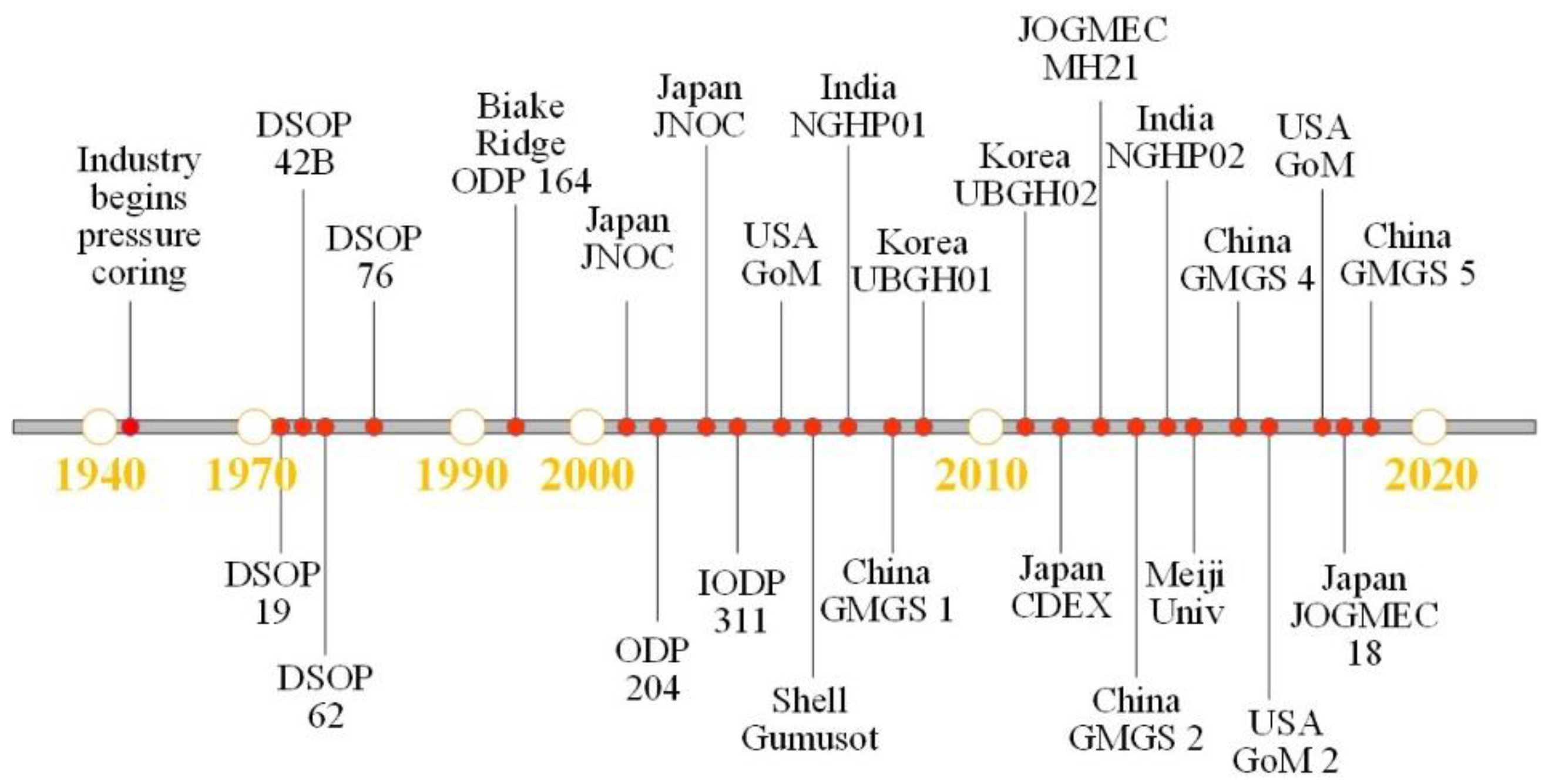
In the early 1970s, the deep-sea drilling program (DSDP) deployed a gas hydrate survey and exploration for the first time [23]. In the mid-1990s, gas hydrate prospect area explorations conducted by the United States, Russia, Japan, Canada, Germany, Netherlands, and other countries, covered most of the continental margins. As the gas hydrate energy potential was confirmed, Japan, China, India, and South Korea successively began their own gas hydrate exploration. Expeditions were carried out in the South China Sea, Nankai Trough, offshore Japan, the north of the South China Sea, the east coast of India, and in the Ulleung Basin of South Korea [24,25,26]. Figure 2 shows the timeline of the major gas hydrate drilling projects around the world. At present, there are more than 100 wells dedicated to gas hydrate research.
Electrical resistivity measurements are one of the most important parameters to identify gas hydrate, and it is widely used in gas hydrate reservoir logging [27,28,29]. Gas hydrate, a natural electrical insulator, can significantly impact the resistivity properties of hydrate-bearing sediments. In addition, hydrate also has a combined effect on the pore water content, ion concentration, and formation skeleton structure, which are critical factors for reservoir electrical properties [30,31,32]. However, the measured resistivity properties of different logging sites around the world vary greatly because of unique tectonic conditions, reservoir mineral composition, gas hydrate stability conditions, and the form of gas hydrate occurrence in sediments.
In order to solve the problems encountered in the logging data interpretation, and to reveal the geophysical properties of gas hydrate-bearing sediment, simulation experiments and numerical analysis have been widely carried out. Scientists have been endeavoring to discover the quantitative relationship between resistivity and gas hydrate saturation, reveal the complex resistivity response of hydrate crystal formation and dissociation processes, and establish a gas hydrate reservoir inversion technique based on resistivity imaging, etc. [33,34,35,36]. However, it can be said that a significant amount of work is required to understand the resistivity properties of hydrate-bearing sediments. The dynamic accumulation and dispersion of gas hydrate in sediments involve the transformation of solid–liquid–gas multiphase materials and core reconstruction at the pore scale, so the electric response mode and control mechanism is complex, leaving many unsolved scientific problems.
Downhole resistivity logging technology is an important method for marine gas hydrate exploration and energy potential evaluation. Affected by the geological factors and the type of gas hydrate accumulation, the reservoirs’ resistivity logging results may vary, and the derived gas hydrate saturation estimates may not be accurate without a complete analysis of all the factors controlling the resistivity properties of the hydrate-bearing sediments. Simulation experiments and theoretical research are effective means to reveal the electrical response controls in different reservoirs. Therefore, this paper gives a summary of the progress related to the marine gas hydrate resistivity logging and experimental research, in order to provide additional insight into the electrical resistivity properties of gas hydrate-bearing sediments.

2. Resistivity Logging Progress of Marine Gas Hydrate

2.1. The South China Sea

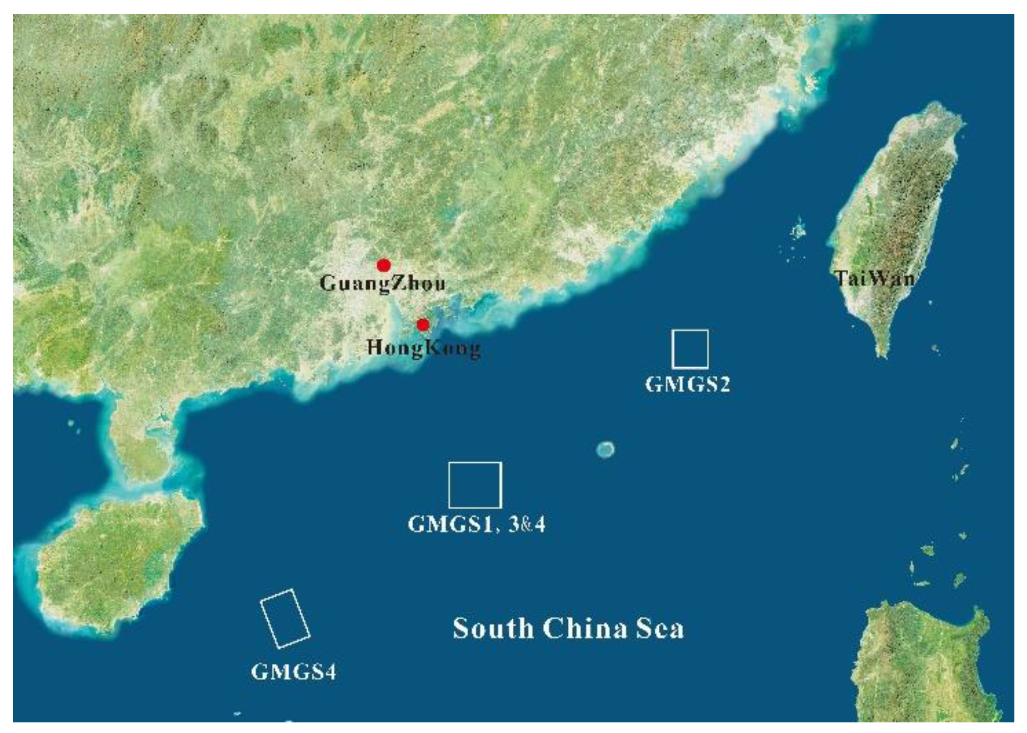
The northern slope of the South China Sea has high-quality gas hydrate reservoir accumulations. China Geological Survey started marine gas hydrate investigations in 1999 [37]. In the past 20 years, exploration expeditions have been conducted from west to east in the South China Sea, including Qiongdongnan Basin, Xisha Trough, Shenhu area, and Dongsha area [38,39,40,41]. Different types of gas hydrate reservoirs were found in these areas (Figure 3).
Shenhu, one of the most studied areas, has been chosen to be the trial production location two times [11]. SH2 was drilled during GMGS1, the downhole logging operations were conducted from about 38 to 245 m below sea floor (mbsf). The resistivity log values increased slowly with the depth. There was a high resistivity anomaly in the depth interval from 189 to 219 mbsf, with the resistivity greater than 3 Ω·m [41]. The W19 gas hydrate research well was drilled during the GMGS3 expedition. The LWD curves of the pilot hole clearly showed the gas hydrate response characteristics, such as high resistivity, high acoustic velocity, and low natural gamma value. There was a 68 m thick resistivity anomaly section between 134~202 mbsf, and the highest resistivity log value was about 8 Ω·m [39]. In addition, the logging results near sites of the two gas hydrate production tests in the Shenhu area showed that the resistivity logging value increased from about 2.5 Ω·m at the top of the hydrate layer to the highest 7.5 Ω·m [42,43].
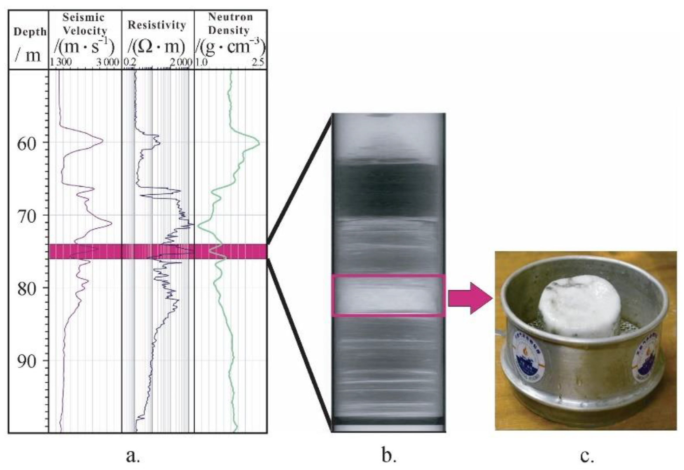
The above described relatively low resistivity anomaly range indicates the presence of pore filling gas hydrate. For the massive gas hydrate reservoir, the resistivity increase was much higher. GMGS2 focused on the continental slope of the northeast Pearl River Mouth Basin, and massive, layered, vein, and dispersed gas hydrates were found in five coring sites [37,40]. The downhole logging data from the W08 well and core samples from the same site confirmed the existence of massive gas hydrate (Figure 4), and the logging data at the depth of 66 to 98 mbsf indicated that the maximum value was more than 2000 Ω·m.
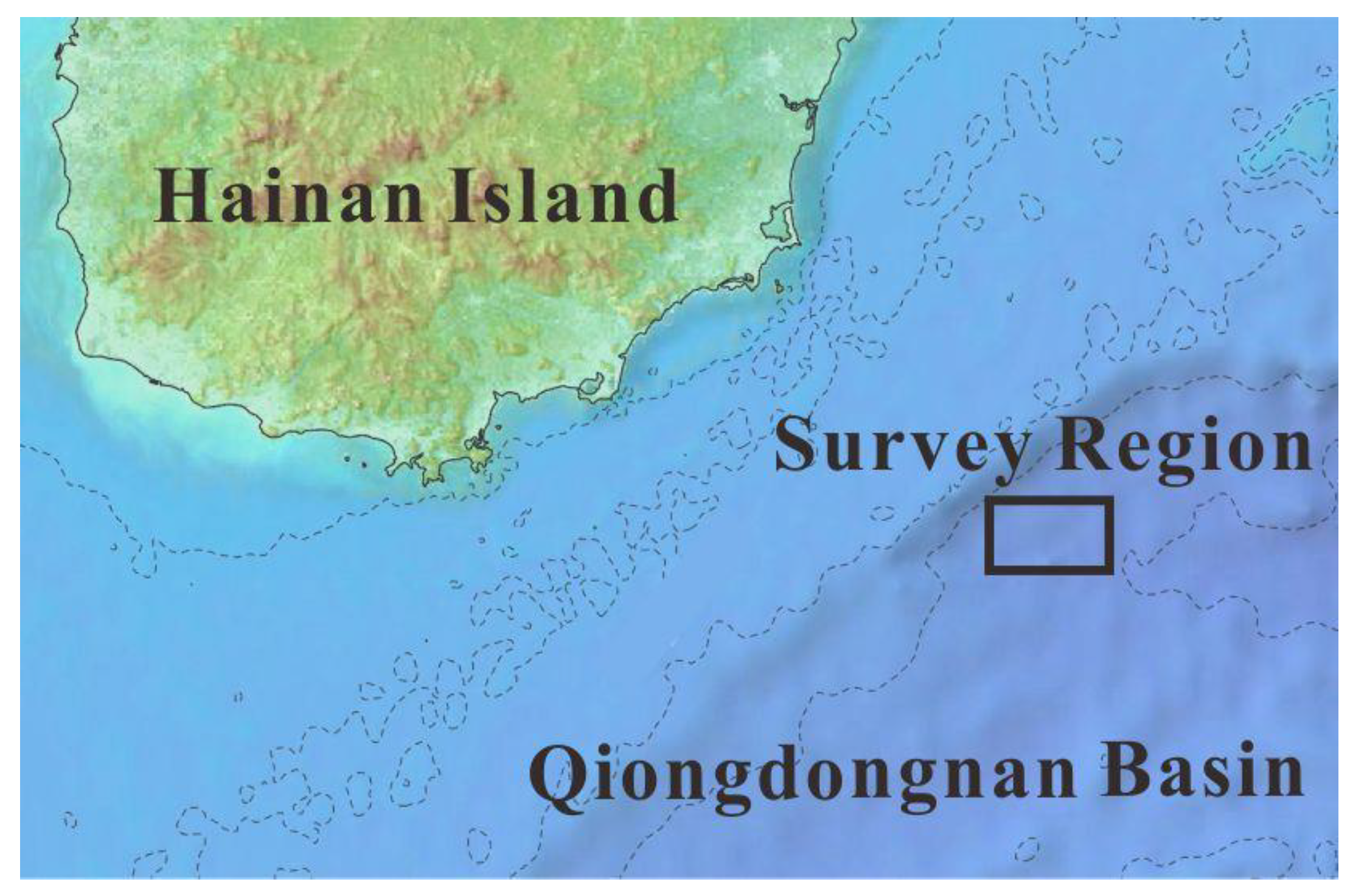
Qiongdongnan Basin is rich in oil and gas resources. The near-seabed pressure and temperature conditions meet the requirements for the stability of gas hydrates [44]. With the aim to image the gas hydrates, a marine controlled-source electromagnetic survey was conducted along a 4.5 km profile, as shown in Figure 5. The inversion results showed that there are numerous laterally discontinuous high resistivity anomalies from 60 to 330 mbsf, and the resistivity in these anomalous intervals ranged from 2 to 10 Ω·m. There were also three additional high resistivity intervals (ranging from 2 to 4 Ω·m) in the W08 below 300 mbsf [45].

2.2. Nankai Trough of Japan

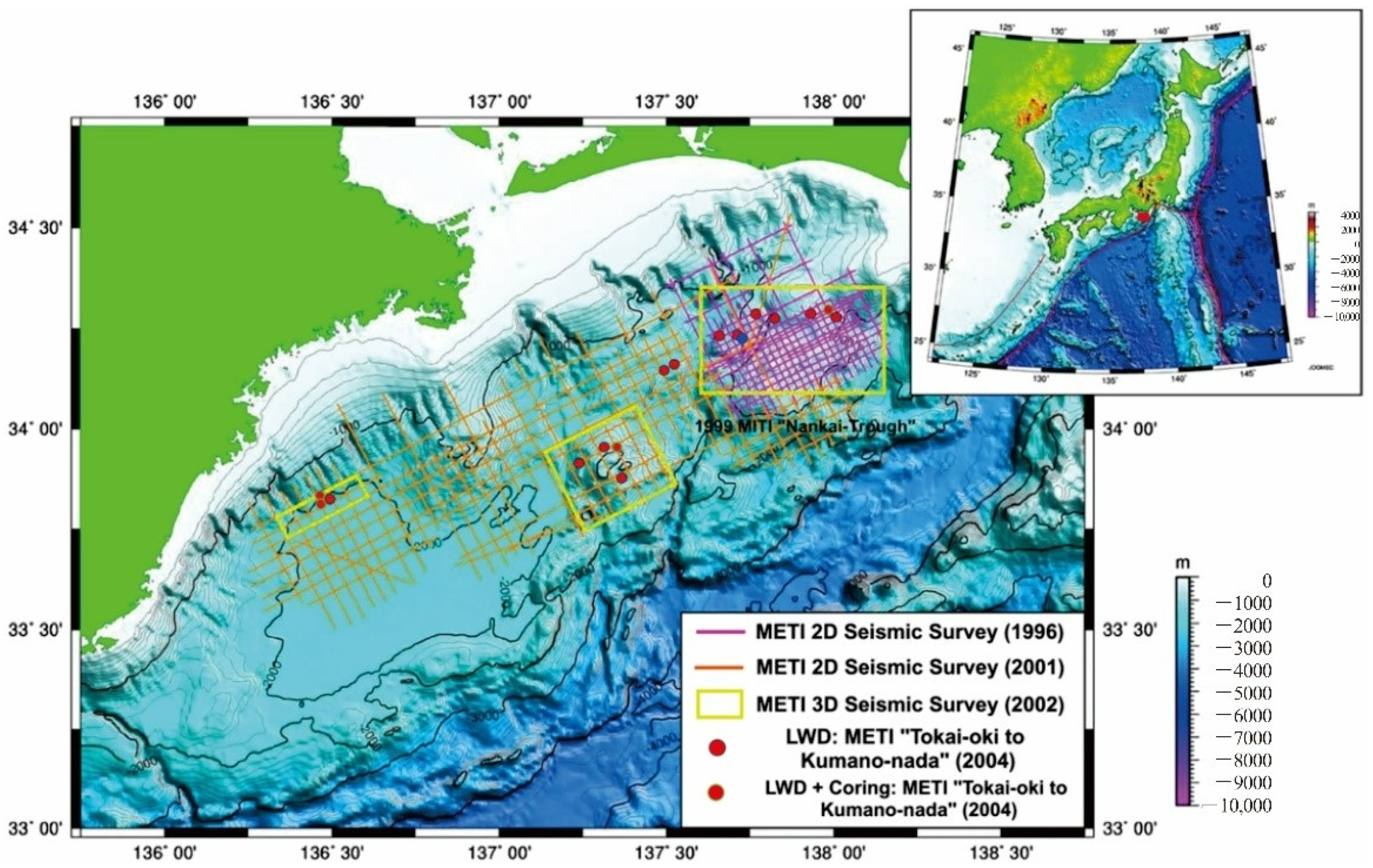
The marine seismic surveys around Japan identified many BSRs. Among the seismic inferred gas hydrate occurrences, the Nankai Trough proved to be the best-known gas hydrate accumulation offshore of Japan. So far, based on the geological exploration and drilling expeditions investigation, two gas hydrate trail production tests have been carried out [12,14]. The Nankai Trough is the southwest portion of the Japanese island arc and was formed by the subduction of the Philippine plate to the Eurasian plate before the Pliocene. The deepest water depth of the trough ranges from 4500 to 4900 m [46]. At present, the exploration locations are mainly distributed along the Daini-Atsumi Knoll (Figure 6) [47].
In 2004, a multi-well exploration campaign in the Nankai Trough was conducted as a national project led by Ministry of Economy, Trade and Industry (METI) of Japan [48,49]. There were 30 wells drilled mainly for geological research purposes and 2 wells drilled for engineering experiment during this campaign. The experimental wells are located in the north end of the Daini-Atsumi Knoll. The formations can be classified into three targeted resistivity log inferred reservoir sections. The muddy portion of the reservoir yielded resistivity log values averaging about 1.5 Ω·m, which is underlain by interbedded methane hydrate and mud layers. The alternated layers were several centimeters to meters in thickness. The formation resistivity log values ranged widely from 2 Ω·m to 30 Ω·m due to the presence of gas hydrate. The non-hydrate bearing formation was at the deepest position, with the resistivity log values ranging from 1.5 to 1.8 Ω·m.

2.3. Ulleung Basin of East Sea

Located on the eastern edge of the Eurasian plate, Ulleung basin is a continental back-arc basin with many block-migration deposits growth. Natural gas hydrate mainly exists in the sandy turbidite layer, which occurs in argillaceous deposits or as vain and fracture-filled. South Korea conducted two gas hydrate expeditions in the Ulleung Basin in 2007 and 2010 (Figure 7) [50].
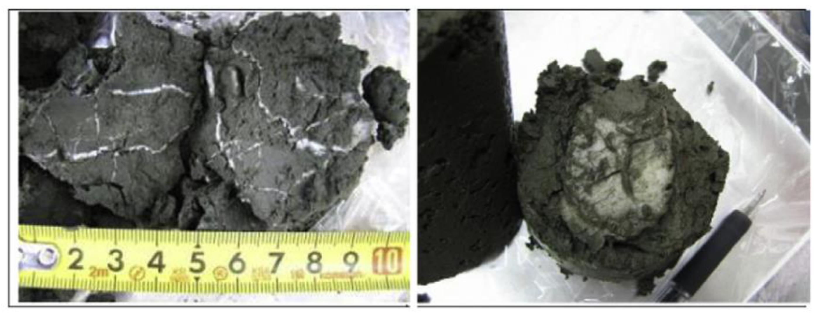
During these expeditions, both vein-filling gas hydrates and pore-filling gas hydrate existed in the reservoir [52]. The resistivity data was acquired by LWD operations [51]. The LWD-tool string (provided by Schlumberger) contained the GeoVision (electrical imaging), EsoScope (propagation resistivity, bulk density, and neutron porosity), TeleScope, and Sonic Vision tools. Here the ring-resistivity log values acquired by the GeoVision were used. The downhole resistivity log data from Sites UBGH1-9 and UBGH1-10 as an example, there were pronounced increases in resistivity log values above the BSR. In UBGH1-9, the resistivity values of the gas hydrates layer increased to over 12 Ω·m and greater values were higher than 80 Ω·m at UBGH1-10. The values seen in these two logs were significantly higher than the unconsolidated sediments of the East Japan Sea [53,54], with an average value of 0.8 Ω·m. These high anomaly resistivity data not only indicate the existence of gas hydrate but also suggest the different types of occurrences. The morphologies of massive or fracture filling hydrate usually are vein, nodule, or lamina (Figure 8) [54], resulting in a high degree of anisotropy, and the resistivity is extremely high.
Riedel et al. used the LWD data of UBGH2 to define the empirical Archie-constants to estimate the gas hydrate saturation [51]. They pointed out that pore filling gas hydrate was more suitable for Archie-based calculations, however, the Archie-constants were still strongly dependent on reservoir properties. For sites located in the northeastern part of the Ulleung Basin, changes in sedimentation patterns within the hemipelagic and turbidite sequences can be linked to patterns in the acquired well log data curves and the correlated to Archie interfered hydrate-bearing reservoirs, at sites located more in the western and southern portion of the basin. The top veneer of hemipelagic and turbidite sediments was mostly absent and the entire depth interval of the gas hydrate stability zone was dominated by stacks of mass transport deposits (MTDs) and Archie inferred interbedded gas hydrate-bearing reservoirs.

2.4. The Krishna–Godavari(K-G) Basin

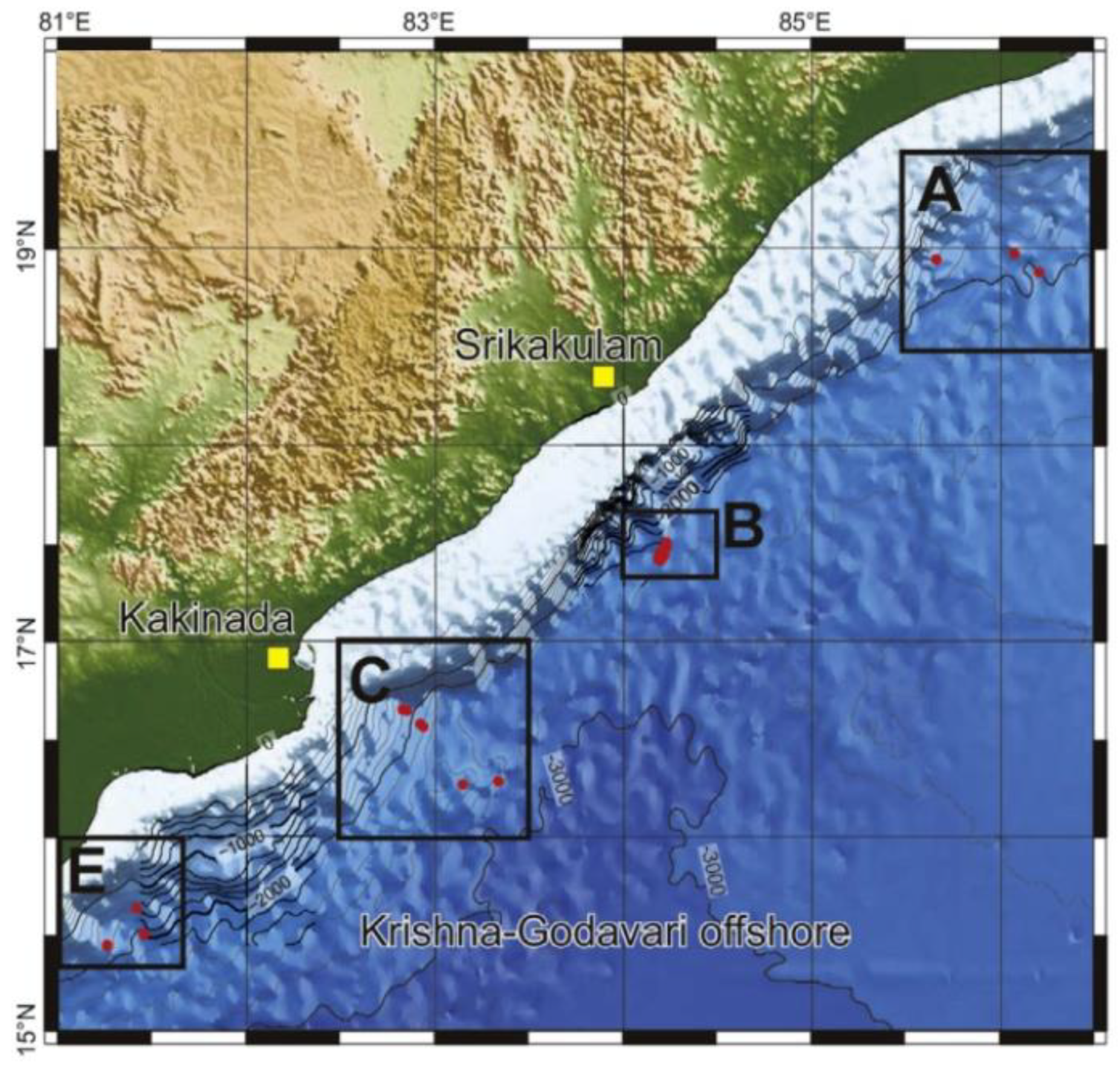
The Krishna–Godavari Basin was formed along the rifted eastern continental margin of India, the offshore K-G Basin is considered a potential gas hydrate province [55]. The Ministry of Petroleum and Natural Gas began the National Gas Hydrates Program (NGHP) in 1997 and implemented NGHP-01 and NGHP-02 in the year 2006 and 2015 [56]. NGHP-01 investigated 21 sites in total, including 12 boreholes for logging while drilling (LWD) and 13 boreholes for wireline logging (WL). NGHP-02 collected LWD and sediment core data in Area B & C offshore of eastern India (Figure 9), to investigate controls on the distribution and peak saturation of methane gas hydrate occurrences in the buried channel, levee, and fan deposits [57].
NGHP-02-07 targeted the upper continental slope channel deposit, NGHP-02-08 targeted levee deposits, and NGHP-02-05 targeted a sequence of fan deposits. Coarse grained sediment exists at each site, but the clay distribution is different. Clay plays an important role in gas hydrate distribution and saturation. Electrical resistivity log data were obtained with the Schlumberger LWD GeoVision resistivity at the bit (RAB) tool. The background resistivity of Area C was about 1 to 2 Ω·m.
The most significant pore-occupying gas hydrate accumulation at Site NGHP-02-07 occurred between 109 to 113 mbsf. Gas hydrate-filled fractures were in fine-grained sediment above and below the primary reservoir unit, characterized by slightly elevated resistivities. The most significant gas hydrate accumulations at Site NGHP-02-08 occurred between 246 to 271 mbsf, but the thinly bedded nature of this site presents a challenge to make direct depth correlations between the LWD results and the recovered sediment core. The main gas hydrate accumulations at Site NGHP-02-05 were between 485 mbsf and the consensus base of hydrate occurrence at 508 mbsf. At certain depths, gas hydrate layers were associated with coarse-grained units, with resistivity as high as about 10 Ω·m.

2.5. The Blake Ridge

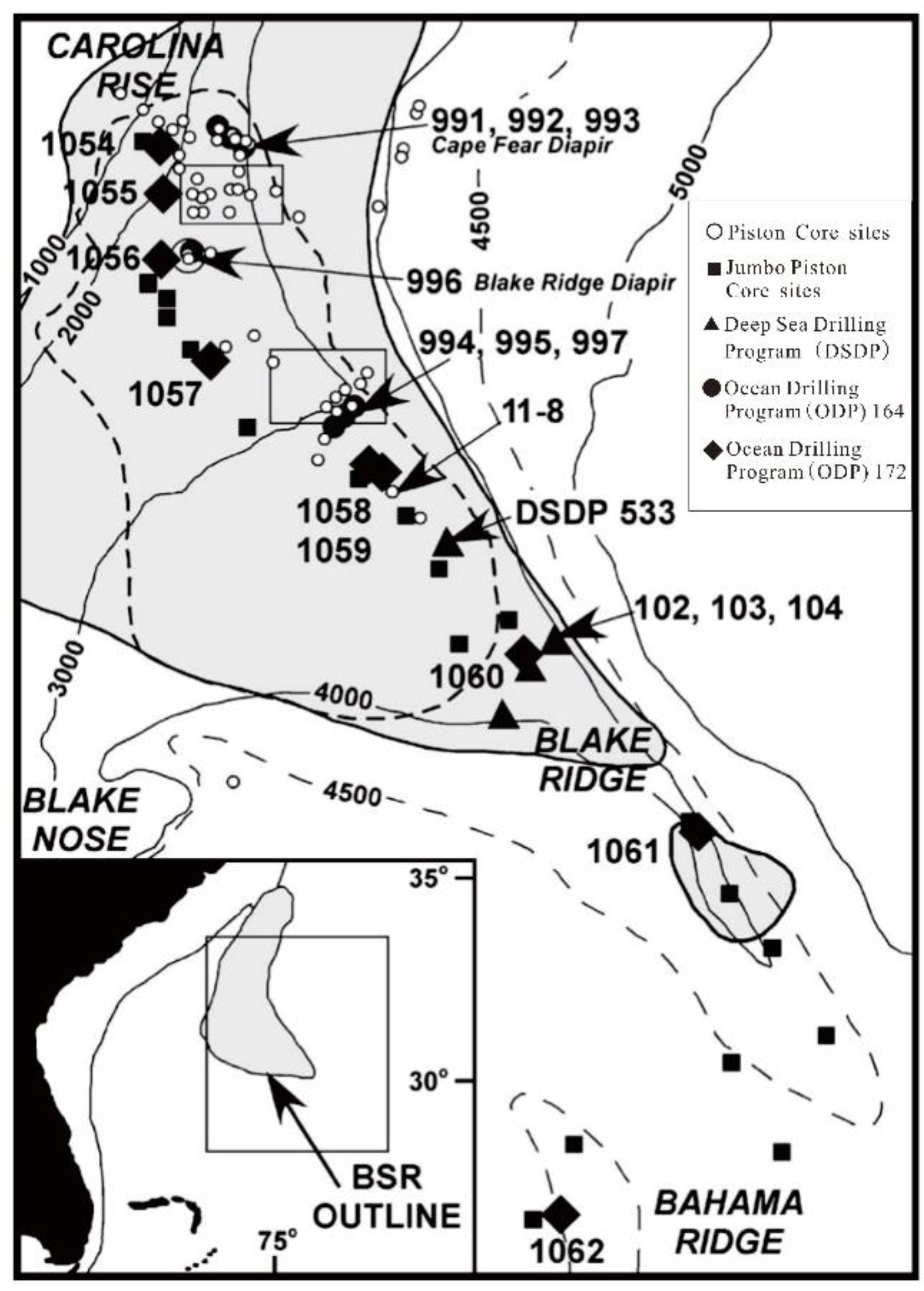
The Blake Ridge is a positive topographic sedimentary feature on the continental slope. The crest of the ridge extends to the general trend of the continental rise from water depths of 2000 to 4800 m. The thickness of the gas hydrate stability zone ranges from zero along the northwestern edge of the continental shelf to a maximum thickness of about 700 m along the eastern edge of the Blake Ridge (Figure 10) [59].
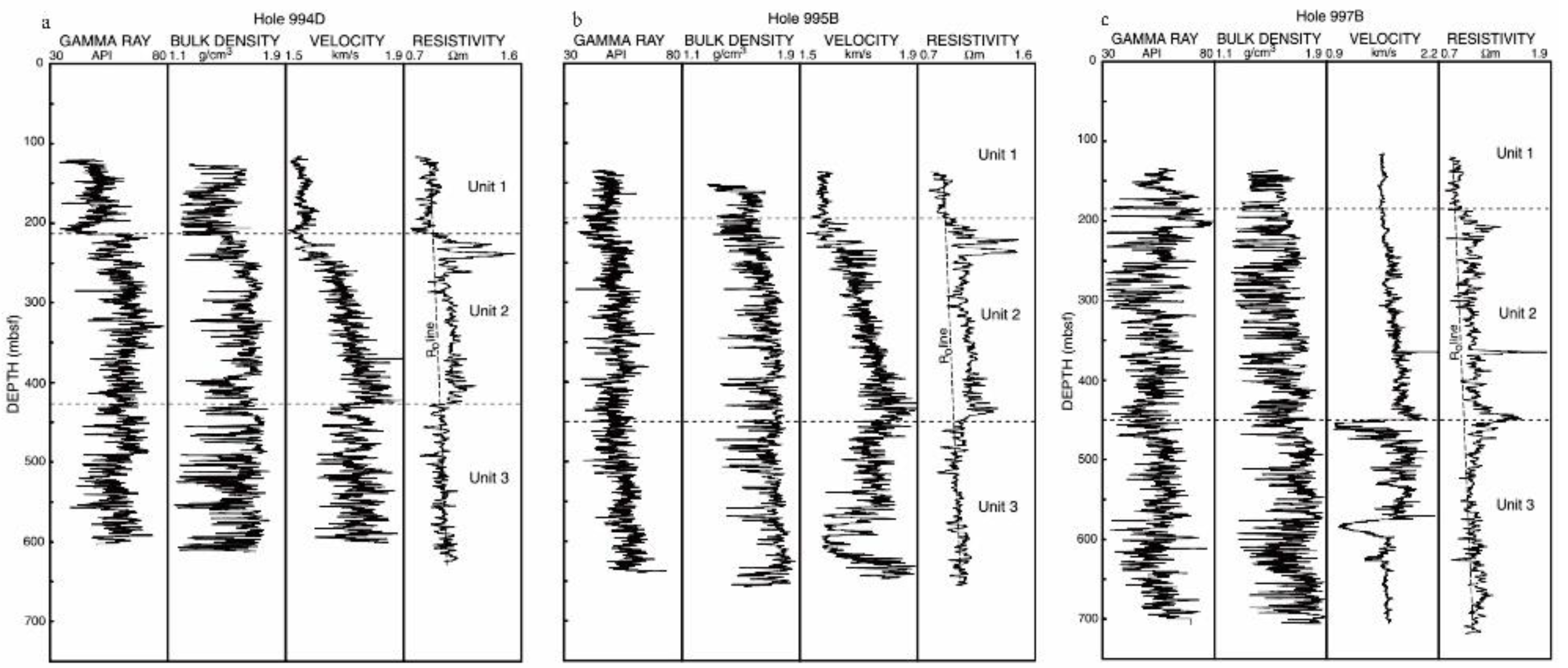
Leg 164 of the Ocean Drilling Program was designed to investigate the occurrence of gas hydrate on the Blake Ridge. Electrical resistivity and other downhole logs from Sites 994, 995, and 997 indicate the presence of gas hydrate in the depth interval between 185 and 450 mbsf. The description of the logged intervals in Holes 994D, 995B, and 997B are shown in Figure 11.
Three units were divided on the base of obvious changes in physical properties. The comparison of logging Units 1, 2, and 3 in these holes revealed that Unit 2 was characterized by a distinct stepwise increase of about 0.1~0.3 Ω·m in resistivity. The deep reading resistivity device revealed several anomalous high resistivity zones within the upper 100 m of Unit 2 at all three sites: anomalous resistivities ranging from 1.4 to 1.5 Ω·m [60].

2.6. Gulf of Mexico

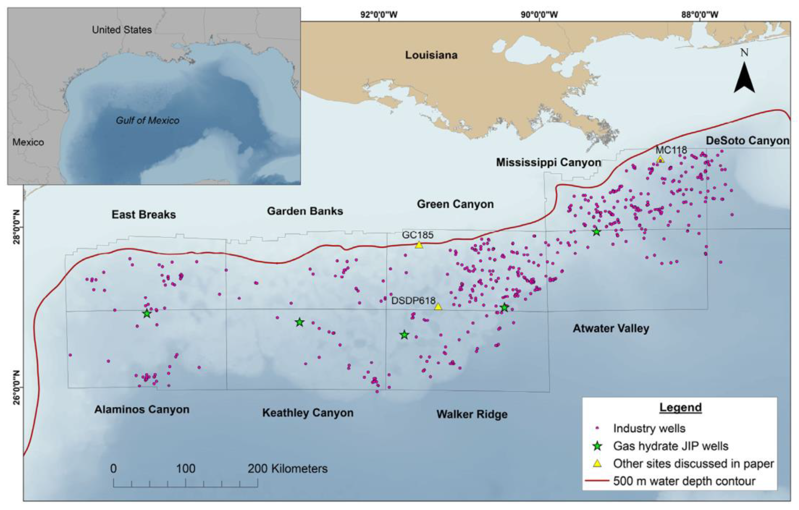
The Gulf of Mexico is a tectonically active and geologically complex environment characterized by faulting, folding, and other deformational processes that largely arise due to the layering of thick sedimentary sequences over buoyant salt deposits [61]. It has been a major location for the exploration of oil and natural gas resources for decades. The first hydrate-focused drilling expedition in this area was the Chevron-led Gulf of Mexico Gas Hydrate Joint Industry Project (JIP) Leg I in 2005, which drilled and cored three sites to evaluate the sediment and borehole stability. During JIP Leg II in 2009, the LWD measurements were used to detect gas hydrate occurrences in sand reservoirs [61,62]. A total of seven holes were drilled at three sites and hydrate was identified in the Green Canyon and Walker Ridge sites in the sand and marine mud reservoirs. Figure 12 shows the 798 petroleum industry wells drilled in this area, including the gas hydrate JIP wells [63].
The electrical resistivity properties of marine sediments are mainly controlled by the conductivity and volume of pore fluids present in the sediment. Setting an appropriate cutoff for the resistivity anomaly that is caused by the presence of gas hydrate is a major challenge. In addition to gas hydrate, several additional factors also yield higher formation resistivities, such as variations in pore–fluid salinities, lithology changes with depth, and the over-compaction of sediments, and so on. Majumdar et al. suggested using the criterion of 0.5 Ω·m or greater increases in formation resistivity as indicative of the presence of gas hydrate [64].
A well from Alaminos Canyon Block 856 was taken as an example. The depth of the base of the gas hydrate stability zone is 2898 m, with a background resistivity of 1 Ω·m. The interpreted gas hydrate interval is at a depth of 2568 to 2611 m with an increase in resistivity of 0.5 Ω·m to a maximum 1 Ω·m above background resistivity [63].

2.7. Cascadia Margin

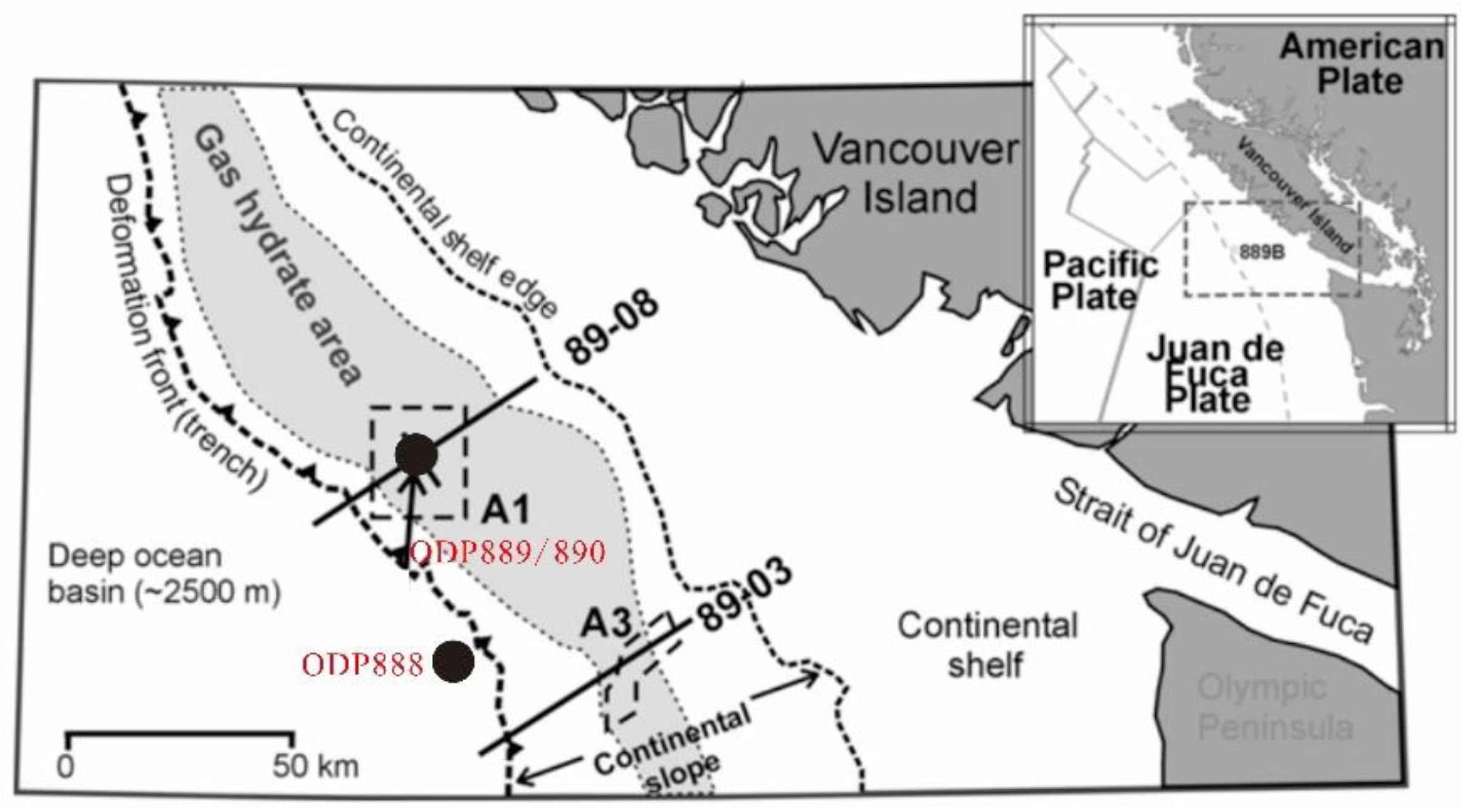
The Cascadia subduction zone extends from northern California to offshore Vancouver Island. The presence of gas hydrate has been established by widespread BSR. However, the major advance in identifying gas hydrate comes from ODP sampling and downhole measurements (Figure 13) [65].
The electrical resistivity logs for Site 888 provide a reference location for a site with no evidence of gas hydrate with an average resistivity log value of 1Ω·m. In contrast, the resistivity for Site 889/890 increased steadily to a value of 2.1 Ω·m for the 100 m above the BSR. There was no sharp resistivity discontinuity at the BSR, but a significant downward decrease appeared in the resistivity log values below the BSR, to about 1.8 Ω·m. The resistivity–depth log can be used along with porosity–depth logs to estimate hydrate saturation [65,67,68].

2.8. Brief Discussion

Gas hydrate is widely spread along the offshore continental slopes, and resistivity measurements are commonly used in geophysical logging. Based on the summary of the electrical resistivity logging results from seven different locations, it can be inferred that the gas hydrate accumulation pattern is the strongest factor in the electrical conduction. The resistivity value of pore-filling gas hydrate sediments is usually lower than 10 Ω·m, while the resistivities of massive or fracture-filling gas hydrate systems are significantly larger. Due to the uneven distribution of gas hydrate, fracture filling gas hydrate shows resistivity anisotropic characteristics. The sedimentary properties also have a great impact on electrical conduction, especially for pore-filling gas hydrate. The resistivity of clay-rich sediment is relatively lower than the coarse sand reservoir.
Although resistivity logging is a reliable method for gas hydrate exploration, there are still significant problems associated with the application of resistivity logging analysis procedures. When the resistivity variation is small, such as in the low gas hydrate saturation locations, the lithology change, over-compaction of sediments, and a pore water salinity decrease can lead to an increase in resistivity logging data. So, a challenge is finding an appropriate cutoff for the resistivity anomaly that could be likely taken as the presence of gas hydrate. Moreover, how to classify the very thin resistivity increases anomaly is another challenge. Taking the Gulf of Mexico resistivity logging as an example where some increases above background occurred as thin spikes, less than 1 m, it is critical to deal with such variability. In addition, precisely evaluating the gas hydrate saturation is always an important challenge. Archie’s equation is suitable for gas hydrate saturation calculations on pore-filling sand reservoirs, but the clay content can make the electrical field distribution more complex, leading to a deviation in Archie’s equation result. Furthermore, there is still a lack of an effective method to calculate the gas hydrate saturation of fractural filling reservoirs.

3. Simulation Experimental Study on Electrical Characteristics of Natural Gas Hydrate

Hydrate crystal growth consumes free water in sediments and fills the pores and fractures of unconsolidated reservoirs, which leads to the highly resistive (i.e., low conductivity) sedimentary sections and reservoirs [69,70,71]. Limited to conditions of deep water, high pressure, and low temperature, gas hydrate reservoirs are difficult and costly to study. Simulation experiments are widely used as an economic and effective research method.

3.1. Simulation Experiment on Electrical Characteristics of Gas Hydrate Bearing Sediments

By analyzing the resistivity data of pure gas hydrate, gas hydrate bearing sediments and permafrost areas, Halleck et al. pointed out that there is a direct correlation between resistance and gas hydrate saturation, so resistivity measurements could be used to detect the presence of gas hydrate in the field [72]. Yousif et al. conducted gas hydrate simulation experiments with a Berea consolidated core. Their results showed that the rate of gas hydrate synthesis and decomposition can be identified by resistivity change [73]. Zatsepina et al. used resistivity change to analyze the nucleation and microcrystalline process of CO2 hydrate [74]. Chen et al. also took advantage of the conductivity of CO2 solutions to detect the nucleation of CO2 hydrate. They found that there is a slight resistivity increase associated with crystal nucleation, which happened before hydrate formation that is also accompanied by a temperature rise [75].
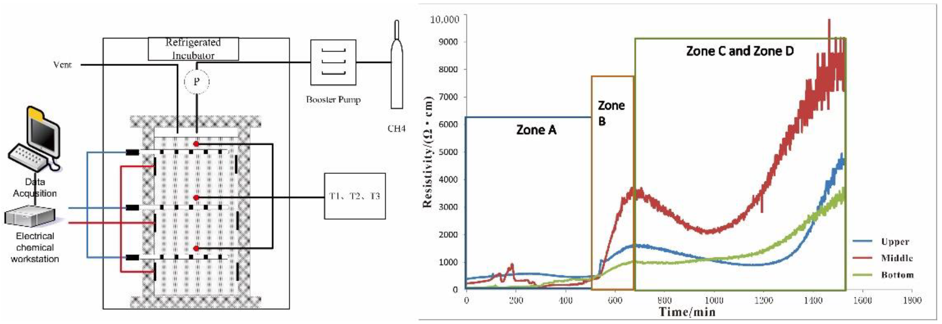
Relative to marine sediment pore water systems, resistivity measurements can also give good information on gas hydrate formation and dissociation processes. Chen et al. tested the resistivity changes during the gas hydrate formation process to analyze the response between gas hydrate distribution and resistivity in marine sediments (Figure 14) [76]. It could be seen that during the gas hydrate formation process, the resistivity experienced four stages of formation from stable to rapidly increasing then relatively decreasing resulting in an overall increase in the measured resistivity as shown in Figure 14. The controlling mechanism behind this phenomenon is a function of temperature, pressure, water saturation, salinity, and gas hydrate distribution.
In the initial stages of gas hydrate formation, if the sediment is saturated with brine, the ion mobility decreases with temperature drop, and pressure has relatively little effect on the resistivity. If the sediment is unsaturated, pore space is partially occupied by saline water. Due to the existence of free gas, when the temperature-drop leads to gas bubble contraction, the fluid connectivity in pores could be improved. In this case, the resistivity change is a product of free gas saturation.
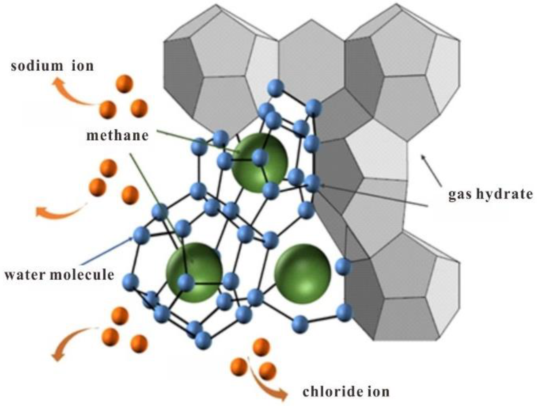
Gas hydrate formation consumes methane molecules and water molecules in pore solution, and salt ions are excluded by this process (Figure 15). Stimulated by the reaction heat, ion mobility is also accelerated. Therefore, even if the connectivity of pores become weak as the insulated hydrate crystal grows, the resistivity still shows a decreasing trend during the gas hydrate formation process [77]. However, with hydrate formation continuing, most of the pore water is replaced by solid hydrate, and the resistivity will continue to increase.
In order to further establish the accurate correlation between gas hydrate and sediment electrical resistivity, and reveal the micro response mechanism, Spangenberg et al. measured the resistivity of gas hydrate formation and the decomposition process in fully water-saturated artificial porous media, and indirectly calculated saturation through free water consumption [78]. They assumed various occurrence modes of gas hydrate in porous media such as cementation and suspension and discussed the main factors leading to resistivity changes in different filling modes (Figure 16).
With the development of X-CT imaging technology, it is possible to acquire the in situ micro distribution information of gas hydrate bearing sediment. A method was established to determine the sediment porosity and identify gas hydrates based on the analysis of X-CT images [79]. Chen et al. carried out a series of simulation experiments to study the resistivity variation during gas hydrate formation in different porous media [80]. During X-CT detection, the nano ray source was selected according to the size of the sample, with a working voltage of 110 kV and working current of 100 μA. The exposure time was 333 ms, the number of X-CT slices was 1000, and the resolution was 28.55 μm/voxel, magnification 7.01.
For each X-CT image of gas hydrate bearing sediment, by counting the calibrated gray values of each image pixel, the gray histogram of the scanning area can be obtained. In order to identify the content and get the micro-distribution of gas hydrate, the threshold between gray adjacent two-phase substances is calculated with the combination of scanning image and gray histogram. The final formula used to calculate gas hydrate saturation is listed below:
S w = i = 1 n P w ( i ) i = 1 n P g ( i ) + i = 1 n P h ( i ) + i = 1 n P w ( i )
where S w is the gas hydrate saturation, P g ( i ) is the pixel of free gas, P h ( i ) is the pixel of gas hydrate, P w ( i ) is the pixel of pore water.
Figure 17 shows the system resistivity variation under different gas hydrate distributions, where the sediment is clay-free sand particles. According to the resistivity change, when gas hydrate saturation increased from 0 to 7.99%, the measured resistivity increased slowly with the increase in gas hydrate saturation, and the resistivity increased from 1.50 Ω· m to 1.63 Ω· m. The X-CT image (stage I) showed that gas hydrate grew along the sediment surface, mainly in the “hydrate–sediment contact” mode.
As gas hydrate saturation increased from 7.99% to 39.24%, and the resistivity increased from 1.63 Ω·m to 3.61 Ω·m. As shown in X-CT images of stage II and III, there were significant gas hydrate particles suspended in pore water, so the gas hydrate micro-distribution mode turned to the coexistence of contact and suspension. In this period, gas hydrate particles have a greater blocking effect on the pore water connection, which results in higher resistivity values. [81].
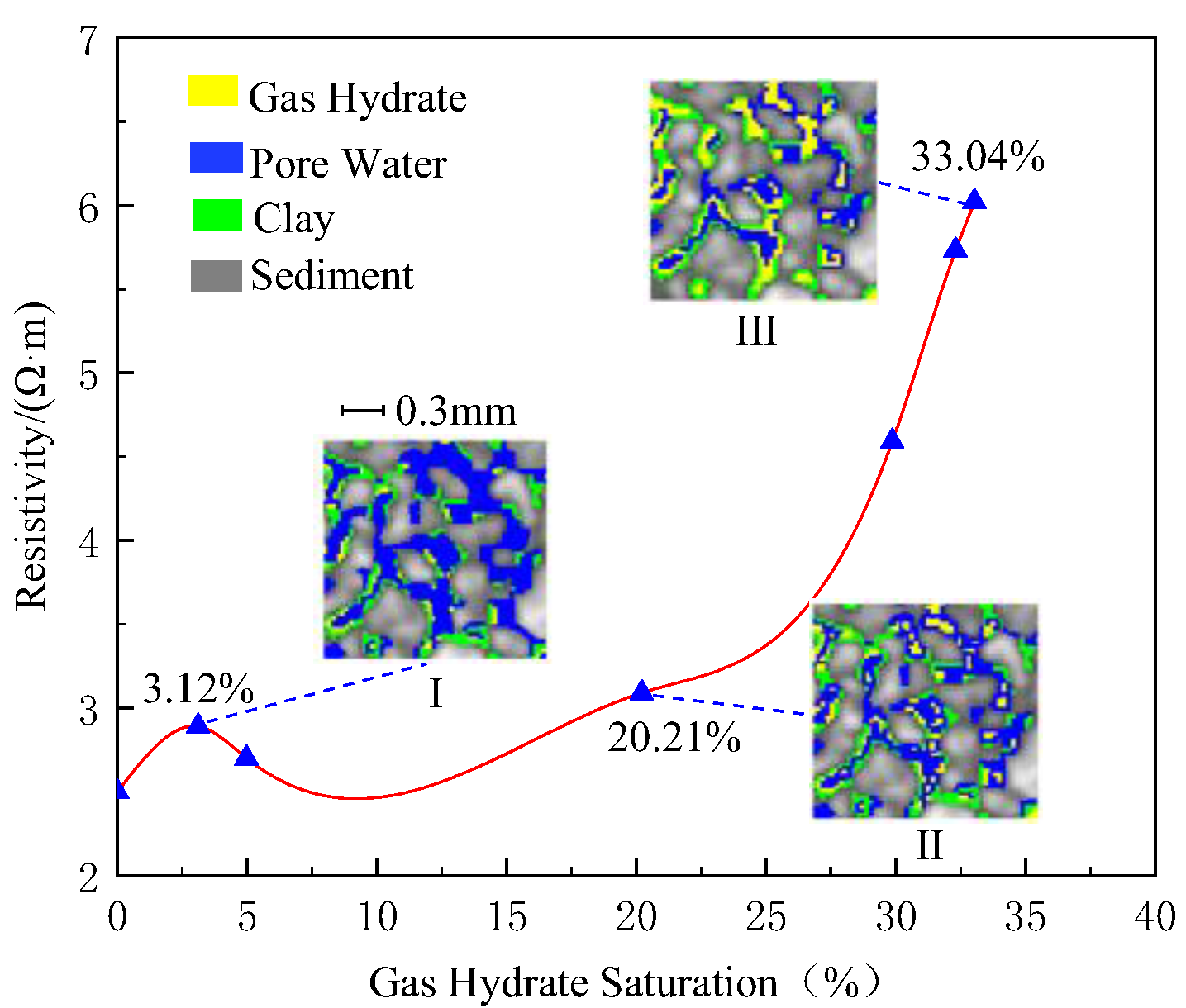
Figure 18 shows the system resistivity variation under gas hydrate distribution in clay-bearing silt sediments. According to the resistivity measurement changes, in the initial stage of gas hydrate formation, the resistivity first increases and then decreases as the gas hydrate saturation rose from 0 to 10%. The X-CT image during stage I showed that gas hydrate grew along the clay layers in a contact distribution mode, and the amount of gas hydrate was relatively small. As the formation process continued, with gas hydrate saturation increasing from 10% to 25%, the resistivity increased slowly with the increasing gas hydrate saturation. As shown in X-CT image stage II, gas hydrate appeared to have formed disseminations (suspension) in the sediment pore space and coexisted with contact formed gas hydrate. In the final stage, the gas hydrate saturation increased from 25% to 33%, and the resistivity increased from 3.3 Ω·m to 6.0 Ω·m. Compared with the clay-free sediment, the resistivity change rate was greater. It is possible clay particles occupied both the large and small pore spaces. Therefore, even at the same gas hydrate saturation, the degree of gas hydrate blocking the pores in clay-bearing sediment was higher and the blocking effect of gas hydrate on pores was stronger, leading to the observed rapid resistivity increase [81].
Chen et al. discussed the numerical simulation of the resistivity of gas hydrate bearing sediment based on the fractal pore model, which can more accurately reflect the actual pore structure [82]. Considering the self-similar characteristic of natural sediments, the Sierpinski Carpet method was selected, with a total side length of three and particle side length of one as the fractal pore model (Figure 19). The effects of porosity, interstitial water conductivity, and sediment skeleton conductivity were analyzed for the relationship between the sediment resistivity and gas hydrate saturation. The results indicated that the resistivity of hydrate bearing sediment can be expressed using this fractal model, especially in the 0 to 40% gas hydrate saturation range. The model is in line with experimental data and logging data with a high degree of accuracy.
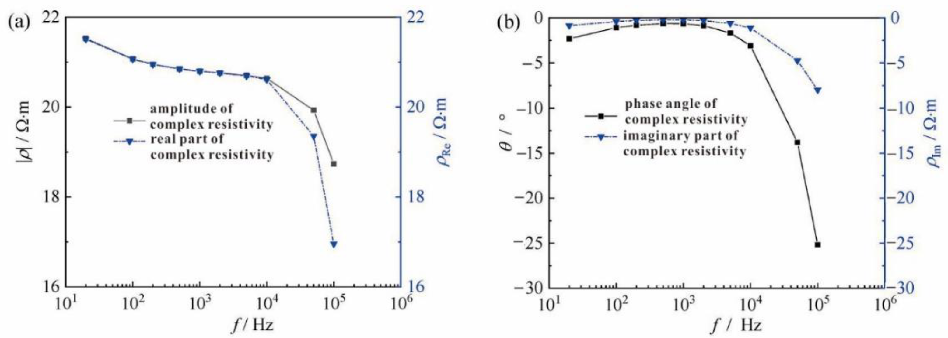
Frequency is another critical factor impacting the resistivity response of different materials. Frane et al. studied the electrical frequency response of the gas hydrate formation process in the range of 20 Hz to2 MHz through a set of complex frequency measurements and analyzed the electrical properties of different system components by the method of equivalent circuit [35,83]. Xing et al. found that the resistivity of gas hydrate bearing sediment showed unique features under different frequencies or types of excitation sources [84,85]. The complex resistivity of hydrate bearing sediment was measured in the frequency range of 20 Hz to 100 kHz (Figure 20). It was demonstrated that the complex resistivity exhibited significant frequency-dispersion characteristics, and the polarization mechanism was dominated by double-layer polarization and interfacial polarization at 20 Hz to 1 kHz and 1 to 100 kHz, respectively. The electrical double-layer polarization of hydrate bearing sediments was enhanced by the deformation of the electrical double layer on the surface of clay particles.
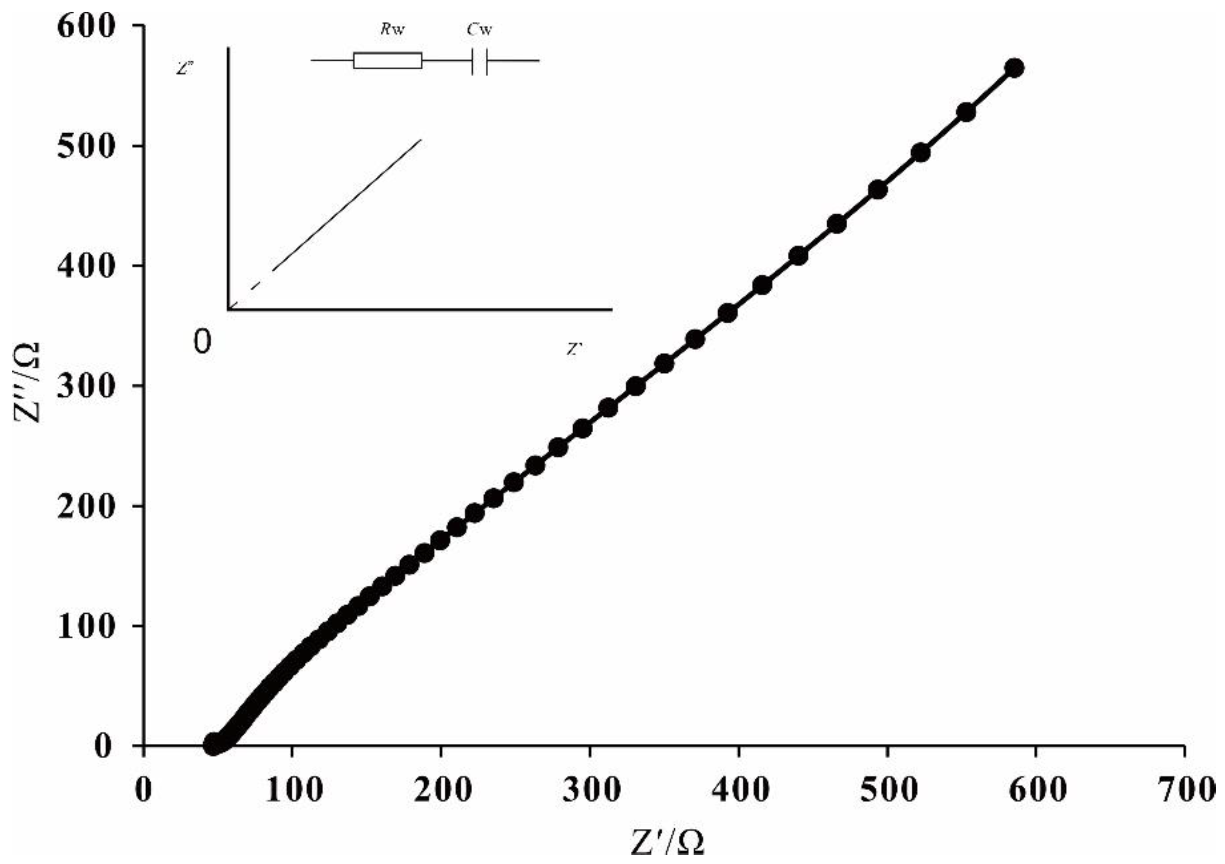
Wang et al. analyzed the complex resistivity parameter based on the impedance spectroscopy of hydrate–porous media and brine system [86]. According to the equivalent circuit model, the relationship between complex resistivity and frequency was established (Figure 21). Then a correlation between the gas hydrate saturation and characteristic parameters of frequency dispersion was found, and finally a new saturation model was proposed with the experimental data fitting results.
Although significant progress has been made to clarify the electrical property of hydrate bearing sediment, the effect of clayey silt on the resistivity properties is still not understood, which restricts the development of gas hydrate saturation evaluation. The clay surface adsorbs cations, and its fine particle size leads to complex pore structure, resulting in more complex electric field distribution. Winsauer et al. proposed that rock resistivity is the result of clay mineral double-layer properties together with parallel of free electrolytes [87]. The effect of the cation exchange in clay minerals on rock resistivity was confirmed by Hill et al. [88], and the cation exchange capacity was used to represent the clay content. Afanasyev et al. analyzed the experimental data and believed that the total resistivity of argillaceous sandstone is the result of parallel conduction of “free ions” and “non free ions” in the pores [89].
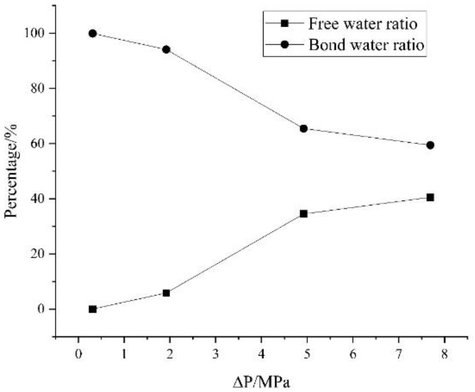
In addition, the formation and decomposition of gas hydrate in clayey silt sediments also change the relative content of free water and bound water. This phenomenon was confirmed by test results of samples from offshore gas hydrate reservoirs in the South China Sea [90]. A high-speed centrifuge was used to test the Shenhu sediment pore water. First, a relationship between centrifuge speed and the pressure was established, which was used to evaluate the free and irreducible water of the reservoir at different pressures during hydrate dissociation. Figure 22 shows the free water and irreducible water variation trends under different pressures. At 0.3 MPa the ratio of free water was very low, and more than 99% pore-water was bounded by sediment. As the pressure increased, irreducible water was released step by step. From 1.9 to 4.9 MPa, the water releasing speed was fast, at 7.9 MPa, there was still 59% of pore water was bounded with sediment.

3.2. Gas Hydrate Saturation Evaluation Models Based on Electrical Property

Archie proposed an equation for calculating oil and gas saturations in sandstone reservoirs with resistivity variation data. It was then improved and applied to the interpretation of gas hydrate resistivity logging data [29,30]. Resistivity of water-saturated formations is directly proportional to the pore water resistivity, and resistivity of hydrate-bearing sediment is proportional to the water-saturated formation. If the formation is composed of sand, the formula of gas hydrate saturation and reservoir resistivity can be defined as:
S h = 1 S w = 1 ( a b ρ w ϕ m ρ t ) 1 n
where S h is the gas hydrate saturation, S w is the pore water saturation, ρ w is the resistivity of pore water, ρ t is the resistivity of hydrate bearing sediment, ϕ is the porosity fraction of sand, a and b are the fitting coefficients, m is the exponent, n is the saturation index.
It is known that the saturation index of the Archie equation is affected by various rock properties (such as pore morphology, connectivity, pore network), and the basic electrical conductivity assumption of Archie equation does not consider the effect of clayey sediments, which adds a complexity when considering normal marine gas hydrate system. In order to optimize the application of the Archie equation in non-sandstone reservoirs, a series of modifications and alternative models have been gradually developed, including the Simandoux model [91], Waxman-Smits model [92], Indonesia equation [91], and Dual-Water model [93]. Taking the Waxman-Smits model as an example, which assumed that the formation resistivity is controlled by clay particles and pore water, and their connection pattern is parallel, then a resistivity model suitable for unsaturated clay containing sediments is proposed.
ρ = a ρ w ϕ m S w 1 n S w + ρ w B Q
where ρ is the sediment resistivity, B is the charge conductivity with an opposite electrical property to the clay surface particles in the electric double layer, Q is the cation exchange capacity per unit sediment pore, B Q is the conductivity of electric double layer on the surface of clay particles.
While effectively improving the accuracy of oil and gas saturation estimation of clay bearing reservoirs, these models also expose new problems. For example, some of them are empirical equations based on macro scale rock models, which are too idealized to deal with the pore structure of low porosity and low permeability reservoirs. Some ignore the actual distribution, geometric shapes, or electrochemical characteristics of clayey components.
In order to further solve the above problems, a skeleton conductivity resistivity model based on HB equation was applied. Song established a general HB model of effective media by treating dispersed mud, rock skeleton, and oil/gas as the dispersed phase with parallel connection [94]. Hu et al. first introduced the HB model to estimate gas hydrate saturation in the Qilian Mountain permafrost area [95]. In addition, Garcia et al. used a high-resolution CT scanner to determine the network geometry and connectivity of clay-bearing cores and proposed a set of resistivity models for oil saturation prediction based on clay composition and rock structure [32]. The new resistivity model incorporates directional pore network connectivity of each conductive component of the rock. The directional connectivity is calculated as a function of the volume fractions and rock fabric features. Clay-bearing cores are scanned using X-CT, and trainable segmentation is performed on each set of 2D raw images to identify different rock components and pores. The 2D-segmented images are then converted into a 3D volume. Finally, the network connectivity and tortuosity from the 3D binary images can be input into the model. The results comparison against conventional methods showed that saturation estimates were improved by up to 50% in more than 60% of the samples after considering the spatial distribution of the clay network.

3.3. Brief Discussion

Simulation experiments play an important role in the gas hydrate-bearing sediment electrical conduction research and field resistivity logging. The experiment findings of resistivity response provide a theoretical basis for the establishment of logging technology. Moreover, the microscopic and mesoscopic-scale resistivity experiment results are very helpful for field logging data explanation. With the assistant of X-CT, resistivity characteristic during gas hydrate growth and dissociation in porous media can be acquired, and it has been found that at different hydrate saturations, the resistivity shows different response sensitivity. At the beginning of gas hydrate formation, high resistance gas bubbles are converted into hydrate particles; the system resistivity changes little, so the amount of gas hydrate would be underestimated by resistivity interpretation.
Archie’s empirical law and its empirical parameters work well in water and oil/gas reservoir systems, but they should be revised in gas hydrate prediction in different reservoir conditions. It has been confirmed that clay minerals have strong effects on electrical conduction and Archie’s equation needs to be modified. Based on experimental results, several fixed models have been proposed to correct for the clay effect on gas hydrate saturation calculations. However, most of them are established under significant restrictive conditions. A universal model has still not been proposed.
Experimental results showed that the utilization of a single frequency current does not completely isolate the different contributions during electrode polarization. The complex resistivity method, such as the electrochemical impedance spectroscopy, has significant potential to separate electrode effects and reveal the conduction mechanisms of sediments with hydrate and clay. More information may be gleaned by measuring the impedance spectroscopy over a broad range of frequencies, which could become a new research hotspot in future. In addition, several experiments on the resistivity data imaging have made progress in gas hydrate sediment, which can provide effective support for the establishment of new technologies to monitor gas hydrate reservoir conditions.

4. Conclusions

Electrical resistivity logging is one of the most useful methods to examine the petrophysical nature of gas hydrate reservoirs and the distribution and concentration of gas hydrates within complex reservoir systems. The logging sensors provide important information on the nature of the sediments and the occurrence of gas hydrate. Integrated sediment coring and well-log research have confirmed that logging data such as electrical resistivity can yield accurate gas hydrate saturations in pore filling reservoirs such as sand reservoirs with isotropic gas hydrate distribution, but more advanced log analysis models are required to characterize gas hydrate in anisotropic fractured reservoirs. According to the logging results of marine gas hydrate reservoirs around the world, the resistivity of pore-filling gas hydrate reservoir is about 1 to 10 Ω·m, clayey silt layers are about 1 to 5 Ω·m or less, and lower than coarse sand layers are about 10 Ω·m. The resistivity of fracture-filling reservoirs are often orders of magnitude higher, usually varying from hundreds Ω·m to thousands Ω·m.
It is worth noting that the anisotropy of natural gas hydrate reservoirs have a direct impact on the resistivity logging results. Most logging tools predominately measure the change in current or electromagnetic waves in the formation of normal to borehole walls. In a vertical hole with flat-lying sediment, measured resistivity is parallel to the bedding planes. Therefore, if sediments and gas hydrate are thinly layered and have dramatically different resistivities, the local resistivity will be underestimated.
A simulating experiment is a useful method to reveal the resistivity control mechanism of gas hydrate-bearing sediments, which is necessary to establish more accurate gas hydrate saturation calculation models. So far as we know, clay induced electrical influence factors such as effective pore-network conductivity and electrical double layer need more study in future.

Author Contributions

Writing—original draft preparation, Q.C.; writing-review and editing, N.W. and Y.L. (Yanlong Li); data collection, C.L., C.Z. and Y.L. (Yang Liu); Cartographer, J.S. and G.H. All authors have read and agreed to the published version of the manuscript.

Funding

This research was funded by the Natural Science Foundation of Shandong Province (ZR202011030013); National Natural Foundation of China (No. 41976205); the Marine S&T Fund of Shandong Province for Pilot National Laboratory for Marine Science and Technology (Qingdao) (No.2021QNLM020002), and the China Geological Survey Program (DD20221704).

Institutional Review Board Statement

Not applicable.

Informed Consent Statement

Not applicable.

Data Availability Statement

Not applicable.

Acknowledgments

Due to their helpful suggestions, thanks are extended to my research team, all members of Key Laboratory of Gas Hydrate, Qingdao Institute of Marine Geology.

Conflicts of Interest

The authors declare no conflict of interest.

References

  1. Boswell, R.; Hancock, S.; Yamamoto, K.; Collett, T.; Pratap, M.; Lee, S.-R. 6-Natural Gas Hydrates: Status of Potential as an Energy Resource. In Future Energy, 3rd ed.; Letcher, T.M., Ed.; Elsevier: Amsterdam, The Netherlands, 2020; pp. 111–131. [Google Scholar]
  2. Sloan, E.D. Clathrate Hydrates of Natural Gases, 2nd ed.; Revised and Expanded; CRC Press: Boca Raton, FL, USA, 1998. [Google Scholar]
  3. Liu, B.; Chen, J.; Pinheiro, L.M.; Yang, L.; Liu, S.; Guan, Y.; Song, H.; Wu, N.; Xu, H.; Yang, R. An insight into shallow gas hydrates in the Dongsha area, South China Sea. Acta Oceanol. Sin. 2021, 40, 136–146. [Google Scholar] [CrossRef]
  4. Matsumoto, R.; Aoyama, C. Verifying Estimates of the Amount of Methane Carried by a Methane Plume in the Joetsu Basin, Eastern Margin of the Sea of Japan. J. Geogr. Chigaku Zasshi 2020, 129, 141–146. [Google Scholar] [CrossRef] [Green Version]
  5. Daigle, H.; Cook, A.; Malinverno, A. Formation of massive hydrate deposits in Gulf of Mexico Sand Layers. Fire Ice 2018, 18, 1–3. [Google Scholar]
  6. Riedel, M.; Collett, T.S.; Shankar, U. Documenting channel features associated with gas hydrates in the Krishna–Godavari Basin, offshore India. Mar. Geol. 2011, 279, 1–11. [Google Scholar] [CrossRef]
  7. Boswell, R.; Shipp, C.; Reichel, T.; Shelander, D.; Saeki, T.; Frye, M.; Shedd, W.; Collett, T.S.; McConnell, D.R. Prospecting for marine gas hydrate resources. Interpretation 2016, 4, SA13–SA24. [Google Scholar] [CrossRef]
  8. Collett, T.; Bahk, J.; Baker, R.; Boswell, R.; Divins, D.; Frye, M.; Goldberg, D.; Husebø, J.; Koh, C.; Malone, M.; et al. Methane Hydrates in Nature—Current Knowledge and Challenges. J. Chem. Eng. Data 2015, 60, 319–329. [Google Scholar] [CrossRef]
  9. Collett, T.S.; Johnson, A.H.; Knapp, C.C.; Boswell, R. Natural gas hydrates—A review. Brows. Collect. 2009, 89, 146–219. [Google Scholar]
  10. Ye, J.L.; Qin, X.W.; Xie, W.W.; Lu, H.L.; Ma, B.J.; Qiu, H.J.; Liang, J.Q.; Lu, J.A.; Kuang, Z.G.; Lu, C.; et al. Main progress of the second gas hydrate trial production in the South China Sea. Geol. China 2020, 47, 557–568. [Google Scholar]
  11. Wu, N.; Li, Y.; Wan, Y.; Sun, J.; Huang, L.; Mao, P. Prospect of marine natural gas hydrate stimulation theory and technology system. Nat. Gas Ind. B 2021, 8, 173–187. [Google Scholar] [CrossRef]
  12. Yamamoto, K.; Wang, X.-X.; Tamaki, M.; Suzuki, K. The second offshore production of methane hydrate in the Nankai Trough and gas production behavior from a heterogeneous methane hydrate reservoir. RSC Adv. 2019, 9, 25987–26013. [Google Scholar] [CrossRef] [Green Version]
  13. Wu, N.Y.; Huang, L.; Hu, G.W.; Li, Y.L.; Chen, Q.; Liu, C.L. Geological controlling factors and scientific challenges for offshore gas hydrate exploitation. Mar. Geol. Quat. Geol. 2017, 37, 1–11. [Google Scholar]
  14. Konno, Y.; Fujii, T.; Sato, A.; Akamine, K.; Naiki, M.; Masuda, Y.; Yamamoto, K.; Nagao, J. Key Findings of the World’s First Offshore Methane Hydrate Production Test off the Coast of Japan: Toward Future Commercial Production. Energy Fuels 2017, 31, 2607–2616. [Google Scholar] [CrossRef]
  15. Giavarini, C.; Hester, K. Methods to Predict Hydrate Formation Conditions and Formation Rate. In Gas Hydrates; Springer: London, UK, 2011; pp. 49–57. [Google Scholar]
  16. Waite, W.F.; Ruppel, C.D.; Boze, L.-G.; Lorenson, T.D.; Buczkowski, B.J.; McMullen, K.Y.; Kvenvolden, K.A. Preliminary Global Database of Known and Inferred Gas Hydrate Locations; U.S. Geological Survey, Coastal and Marine Hazards and Resources Program: Woods Hole, MA, USA, 2020.
  17. Bhade, P.; Phirani, J. Effect of geological layers on hydrate dissociation in natural gas hydrate reservoirs. J. Nat. Gas Sci. Eng. 2015, 26, 1549–1560. [Google Scholar] [CrossRef]
  18. Li, F.; Yuan, Q.; Li, T.; Li, Z.; Sun, C.; Chen, G. A review: Enhanced recovery of natural gas hydrate reservoirs. Chin. J. Chem. Eng. 2018, 27, 2062–2073. [Google Scholar] [CrossRef]
  19. Ning, F.L.; Liang, J.Q.; Wu, N.Y.; Zhu, Y.H.; Wu, S.G.; Liu, C.L.; Wei, C.F.; Wang, D.D.; Zhang, Z.; Xu, M.; et al. Reservoir characteristics of natural gas hydrates in China. Nat. Gas Ind. 2020, 40, 1–24. [Google Scholar]
  20. Wang, L.F.; Fu, S.Y.; Liang, J.Q.; Shang, J.J.; Wang, J.L. A review on gas hydrate developments propped by worldwide national projects. Geol. China 2017, 44, 439–448. [Google Scholar]
  21. Guan, J.A.; Fan, S.S.; Liang, D.Q.; Wan, L.H.; Li, D.L. An overview on gas hydrate exploration and exploitation in natural fields. Adv. New Renew. Energy 2019, 7, 522–531. [Google Scholar]
  22. Berndt, C.; Bünz, S.; Clayton, T.; Mienert, J.; Saunders, M. Seismic character of bottom simulating reflectors: Examples from the mid-Norwegian margin. Mar. Pet. Geol. 2004, 21, 723–733. [Google Scholar] [CrossRef]
  23. Paull, C.K.; Ussler, W., III. History and significance of gas sampling during DSDP and ODP drilling associated with gas hydrates. In Natural Gas Hydrates: Occurrence, Distribution, and Detection; Geophysical Monograph Series; American Geophysical Union: Washington, DC, USA, 2001; Volume 124, pp. 53–65. [Google Scholar]
  24. Zhang, T.; Ran, H.; Xu, J.J.; Sha, Z.B.; Jiang, Y.; Wang, K. Research and development progress as well as technical orientation of the natural gas hydrate in Japan. Acta Geosci. Sin. 2021, 42, 196–202. [Google Scholar]
  25. Wang, S.L.; Sun, Z.T. Current status and future trends of exploration and pilot production of gas hydrate in the world. Mar. Geol. Front. 2018, 34, 24–32. [Google Scholar]
  26. Sha, Z.; Xu, Z.; Wang, P.; Liang, Q.; Wan, X.; Wang, L.; Su, P. World progress in gas hydrate research and its enlightenment to accelerating industrialization in China. Mar. Geol. Front. 2019, 35, 1–10. [Google Scholar]
  27. Qian, J.; Wang, X.; Collett, T.S.; Guo, Y.; Kang, D.; Jin, J. Downhole log evidence for the coexistence of structure II gas hydrate and free gas below the bottom simulating reflector in the South China Sea. Mar. Pet. Geol. 2018, 98, 662–674. [Google Scholar] [CrossRef]
  28. Collett, T.S.; Boswell, R.; Waite, W.F.; Kumar, P.; Roy, S.K.; Chopra, K.; Singh, S.K.; Yamada, Y.; Tenma, N.; Pohlman, J.; et al. India National Gas Hydrate Program Expedition 02 Summary of Scientific Results: Gas hydrate systems along the eastern continental margin of India. Mar. Pet. Geol. 2019, 108, 39–142. [Google Scholar] [CrossRef]
  29. Zhang, Z.; Wright, C.S. Quantitative interpretations and assessments of a fractured gas hydrate reservoir using three-dimensional seismic and LWD data in Kutei basin, East Kalimantan, offshore Indonesia. Mar. Pet. Geol. 2017, 84, 257–273. [Google Scholar] [CrossRef]
  30. Wang, X.J.; Wu, S.G.; Liu, X.W.; Guo, Y.Q.; Lu, J.A.; Yang, S.X.; Liang, J.Q. Estimation of gas hydrate saturation based on resistivity logging and analysis of estimation error. Geoscience 2010, 24, 993–999. [Google Scholar]
  31. Gongli, W.; Aria, A.; David, A.; Yan, S. Determining anisotropic resistivity in the presence of invasion with triaxial induction data. In Proceedings of the SPWLA 58th Annual Logging Symposium, Oklahoma City, OK, USA, 17–21 June 2017; pp. 1–12. [Google Scholar]
  32. Garcia, A.P.; Jagadisan, A.; Rostami, A.; Heidari, Z. A New Resistivity-Based model for Improved Hydrocarbon Saturation Assessment in Clay-Rich Formation using Quantitative Clay Network Geometry and Rock Fabric. In Proceedings of the SPWLA 58th Annual Logging Symposium, Oklahoma City, OK, USA, 17–21 June 2017. [Google Scholar]
  33. Chen, Y.F.; Zhou, X.B.; Liang, D.Q.; Wu, N.Y. Resistivity changes of natural gas hydrate formation and dissociation in sediments. Nat. Gas Geosci. 2018, 29, 1672–1678. [Google Scholar]
  34. Lim, D.; Ro, H.; Seo, Y.; Lee, J.Y.; Lee, J.; Kim, S.; Park, Y.; Lee, H. Electrical resistivity measurements of methane hydrate during N/CO gas exchange. Energy Fules 2016, 31, 708–713. [Google Scholar] [CrossRef]
  35. Du Frane, W.L.; Stern, L.A.; Weitemeyer, K.A.; Constable, S.; Pinkston, J.C.; Roberts, J.J. Electrical properties of polycrystalline methane hydrate. Geophys. Res. Lett. 2011, 38. [Google Scholar] [CrossRef]
  36. Chen, L.-T.; Li, N.; Sun, C.-Y.; Chen, G.-J.; Koh, C.A.; Sun, B.-J. Hydrate formation in sediments from free gas using a one-dimensional visual simulator. Fuel 2017, 197, 298–309. [Google Scholar] [CrossRef]
  37. Liang, J.Q.; Zhang, G.X.; Lu, J.A.; Su, P.B.; Sha, Z.B.; Gong, Y.H.; Su, X. Accumulation characteristics and genetic models of natural gas hydrate reservoirs in the NE slope of the South China Sea. Nat. Gas Ind. 2016, 36, 152–162. [Google Scholar]
  38. Zhang, W.; Liang, J.Q.; Lu, J.A.; Wei, J.G.; Su, P.B.; Fang, Y.X.; Guo, Y.Q.; Yang, S.X.; Zhang, G.X. Accumulation features and mechanisms of high saturation natural gas hydrate in Shenhu area, norther South China Sea. Pet. Explor. Dev. 2017, 44, 670–680. [Google Scholar] [CrossRef]
  39. Zhang, W.; Liang, J.Q.; He, J.X.; Cong, X.R.; Su, P.B.; Lin, L.; Liang, J. Differences in natural gas hydrate migration and accumulation between GMGS1 and GMGS3 drilling areas in the Shenhu area, northern South China Sea. Nat. Gas Ind. 2018, 38, 138–149. [Google Scholar]
  40. Wei, J.G.; Yang, S.X.; Liang, J.Q.; Lu, J.A.; Liu, S.X.; Zhang, W. Impact of seafloor drilling on methane seepage- enlightenments from natural gas hydrate drilling site GMGS2-16, northern South China Sea. Mar. Geol. Quat. Geol. 2018, 38, 63–70. [Google Scholar]
  41. Liu, J.; Zhang, J.Z.; Sun, Y.B.; Zhao, T.H. Gas hydrate reservoir parameter evaluation using logging data in the Shenhu area, South China Sea. Nat. Gas Geosci. 2017, 28, 164–172. [Google Scholar]
  42. Qin, X.-W.; Lu, J.-A.; Lu, H.-L.; Qiu, H.-J.; Liang, J.-Q.; Kang, D.-J.; Zhan, L.-S.; Lu, H.-F.; Kuang, Z.-G. Coexistence of natural gas hydrate, free gas and water in the reservoir system in the Shenhu Area, South China Sea. China Geol. 2020, 3, 210–220. [Google Scholar]
  43. Kang, D.; Lu, J.; Zhang, Z.; Liang, J.; Kuang, Z.; Lu, C.; Kou, B.; Lu, Q.; Wang, J. Fine-grained gas hydrate reservoir properties estimated from well logs and lab measurements at the Shenhu gas hydrate production test site, the northern slope of the South China sea. Mar. Pet. Geol. 2020, 122, 104676. [Google Scholar] [CrossRef]
  44. Chen, M.; Liao, J.; Ouyang, M.; Sun, D.Q.; Qu, W.C.; Cai, H.M. Characteristics and exploration potential of gas hydrate reservoir in Songnan low Uplift, Qiongdongnan Basin. Well Logging Technol. 2021, 4, 290–296. [Google Scholar]
  45. Jing, J.E.; Zhao, Q.X.; Deng, M.; Luo, X.H.; Chen, K.; Wang, M.; Tu, G.H. A study on natural gas hydrates and their forming model using marine controlled source electromagnetic survey in the Qiongdongnan Basin. Chin. J. Geophys. 2018, 61, 4677–4689. [Google Scholar]
  46. Fujii, T.; Suzuki, K.; Takayama, T.; Tamaki, M.; Komatsu, Y.; Konno, Y.; Yoneda, J.; Yamamoto, K.; Nagao, J. Geological setting and characterization of a methane hydrate reservoir distributed at the first offshore production test site on the Daini-Atsumi Knoll in the eastern Nankai Trough, Japan. Mar. Pet. Geol. 2015, 66, 310–322. [Google Scholar] [CrossRef]
  47. Noguchi, S.; Shimoda, N.; Takano, O.; Oikawa, N.; Inamori, T.; Saeki, T.; Fujii, T. 3-D internal architecture of methane hydrate-bearing turbidite channels in the eastern Nankai Trough, Japan. Mar. Pet. Geol. 2011, 28, 1817–1828. [Google Scholar] [CrossRef]
  48. Takahashi, H.; Tsuji, Y. Multi-well exploration program in 2004 for natural hydrates in the Nankai-Trough offshore Japan. In Proceedings of the 2005 Offshore Technology Conference, Houston, TX, USA, 2–5 May 2005. [Google Scholar]
  49. Matsuzawa, M.; Umezu, S.; Yamamoto, K. Evaluation of experiment program 2004: Natural hydrate exploration campaign in the Nankai-Trough Offshore Japan. In Proceedings of the IADC/SPE Drilling Conference, Miami, FL, USA, 21–23 February 2006. [Google Scholar]
  50. Bahk, J.; Kim, D.; Chun, J. Gas hydrate occurrences and thier relation to host sediment properties: Results from Second Ulleung Basin Gas Hydrate Drilling Expedition, East Sea. Mar. Pet. Geol. 2013, 47, 21–29. [Google Scholar] [CrossRef]
  51. Riedel, M.; Collett, T.S.; Kim, H.S.; Bahk, J.J.; Kim, J.H.; Ryu, B.J.; Kim, G.Y. Large-scale depositional characteristics of the Ulleung Basin and its impact on electrical resistivity and Archie-parameters for gas hydrate saturation estimates. Mar. Pet. Geol. 2013, 47, 222–235. [Google Scholar] [CrossRef]
  52. Kim, G.Y.; Yi, B.Y.; Yoo, D.G.; Ryu, B.J.; Riedel, M. Evidence of gas hydrate from downhole logging data in the Ulleung Basin, East Sea. Mar. Pet. Geol. 2011, 28, 1979–1985. [Google Scholar] [CrossRef]
  53. Kim, G.Y.; Yoo, D.G.; Lee, Y.J.; Kim, D.C. The relationship between silica diagenesis and physical properties in the East Japan Sea: ODP Legs 127/128. J. Asian Earth Sci. 2007, 30, 448–456. [Google Scholar] [CrossRef]
  54. Kang, D.H.; Yoo, D.G.; Bahk, J.J.; Ryu, B.J.; Koo, N.H.; Kim, W.S.; Park, K.P. The occurrence patterns of gas hydrate in the Ulleung Basin, East Sea. J. Geol. Soc. Korea 2009, 45, 143–155. [Google Scholar]
  55. Shukla, K.M.; Kumar, P.; Yadav, U.S. Gas hydrate reservoir identification, delineation and characterization in the Krishna-Godavari Basin using subsurface geologic and geophysical data from the National Gas Hydrate Program 02. Mar. Pet. Geol. 2018, 108, 185–205. [Google Scholar] [CrossRef]
  56. Kumar, P.; Collett, T.S.; Shukla, K.M.; Yadav, U.S.; Lall, M.V.; Vishwanath, K. India National gas hydrate program expedition 02: Operational and technical summary. Mar. Pet. Geol. 2019, 108, 3–38. [Google Scholar] [CrossRef]
  57. Waite, W.; Jang, J.; Collett, T.; Kumar, P. Downhole physical property-based description of a gas hydrate petroleum system in NGHP-02 Area C: A channel, levee, fan complex in the Krishna-Godavari Basin offshore eastern India. Mar. Pet. Geol. 2018, 108, 272–295. [Google Scholar] [CrossRef]
  58. Hsiung, K.-H.; Saito, S.; Kanamatsu, T.; Sanada, Y.; Yamada, Y. Regional stratigraphic framework and gas hydrate occurrence offshore eastern India: Core-log-seismic integration of National Gas Hydrate Program Expedition 02 (NGHP-02) Area-B drill sites. Mar. Pet. Geol. 2019, 108, 206–215. [Google Scholar] [CrossRef]
  59. Borowski, W.S. A review of methane and gas hydrates in the dynamic, stratified system of the Blake Ridge region, offshore southeastern North America. Chem. Geol. 2004, 205, 311–346. [Google Scholar] [CrossRef]
  60. Collett, T.S.; Ladd, J. Detection of gas hydrate with downhole logs and assessment of gas hydrate concentrations (saturations) and gas volumes on the Blake Ridge with electrical resistivity. In Proceedings of the Ocean Drilling Program, Scientific Results; Paull, C.K., Matsumoto, R., Eds.; Ocean Drilling Program: College Station, TX, USA, 2000; pp. 179–191. [Google Scholar]
  61. Francisca, F.M.; Yun, T.-S.; Ruppel, C.; Santamarina, J. Geophysical and geotechnical properties of near-seafloor sediments in the northern Gulf of Mexico gas hydrate province. Earth Planet. Sci. Lett. 2005, 237, 924–939. [Google Scholar] [CrossRef]
  62. Collett, T.S.; Lee, M.W.; Zyrianova, M.V.; Mrozewski, S.A.; Guerin, G.; Cook, A.E.; Goldberg, D.S. Gulf of Mexico Gas Hydrate Joint Industry Project Leg II logging-while-drilling data acquisition and analysis. Mar. Pet. Geol. 2012, 34, 41–61. [Google Scholar] [CrossRef]
  63. Majumdar, U.; Cook, A.E.; Scharenberg, M.; Burchwell, A.; Ismail, S.; Frye, M.; Shedd, W. Semi-quantitative gas hydrate assessment from petroleum industry well logs in the northern Gulf of Mexico. Mar. Pet. Geol. 2017, 85, 233–241. [Google Scholar] [CrossRef]
  64. Majumdar, U.; Cook, A.E.; Sheed, W.; Frye, M. The connection between natural gas hydrate and bottom-simulating reflectors. Geophys. Res. Lett. 2016, 43, 7044–7051. [Google Scholar] [CrossRef]
  65. Hyndman, R.D.; Spence, G.D.; Chapman, N.R.; Riedel, M.; Edwards, R.N. Geophysical studies of marine gas hydrate in Northern Cascadia. In Natural Gas Hydrates: Occurrence, Distribution, and Detection; American Geophysical Union: Washington, DC, USA, 2001. [Google Scholar]
  66. Pohlman, J.W.; Canuel, E.A.; Chapman, N.R.; Spence, G.D.; Whiticar, M.J.; Coffin, R.B. The origin of thermogenic gas hydrate s on the northern Cascadia Margin as inferred from isotopic (13C/12C and D/H) and molecular composition of hydrate and vent gas. Org. Geochem. 2005, 36, 703–716. [Google Scholar] [CrossRef]
  67. Chen, M.A.P.; Riedel, M.; Spence, G.D.; Hyndman, R.D. Data report: A downhole electrical resistivity study of northern Cascadia marine gas hydrate. In Proceedings of the Integrated Ocean Drilling Program; Texas A & M University: College Station, TX, USA, 2008. [Google Scholar]
  68. Riedel, M.; Spence, G.D.; Chapman, N.R.; Hyndman, R.D. Deep-sea gas hydrates on the northern Cascadia margin. In The Leading Edge; Society of Exploration Geophysicists: Houston, TX, USA, 2012; Volume 20. [Google Scholar]
  69. Tabbagh, A.; Cosenza, P. Effect of microstructure on the electrical conductivity of clay-rich systems. Phys. Chem. Earth 2007, 32, 154–160. [Google Scholar] [CrossRef]
  70. Lee, J.Y.; Francisca, F.M.; Santamarina, J.C.; Ruppel, C. Parametric study of the physical properties of hydrate-bearing sand, silt, and clay sediments: 2. Small-strain mechanical properties. J. Geophys. Res. 2010, 115. [Google Scholar] [CrossRef]
  71. Ning, F.L.; Liu, L.; Li, S.; Zhang, K.; Jiang, G.S.; Wu, N.Y.; Sun, C.Y.; Chen, G.J. Well logging assessment of natural gas hydrate reservoirs and relevant influential factors. Acta Pet. Sin. 2013, 34, 591–606. [Google Scholar]
  72. Pearson, C.F.; Halleck, P.M.; McGuire, P.L.; Hermes, R.; Mathews, M. Natural gas hydrate deposits: A review of in situ properties. J. Phys. Chem. 1983, 87, 4180–4185. [Google Scholar] [CrossRef] [Green Version]
  73. Youslf, M.H.; Sloan, E.D. Experimental Investigation of Hydrate Formation and Dissociation in Consolidated Porous Media. SPE Reserv. Eng. 1991, 6, 452–458. [Google Scholar] [CrossRef]
  74. Zatsepina, Y.O.; Buffett, B.A. Nucleation of CO2-hydrate in a porous medium. Fluid Phase Equilibria 2002, 200, 263–275. [Google Scholar] [CrossRef]
  75. Chen, Q.; Liu, C.L.; Ye, Y.G.; Diao, S.B.; Zhang, J. Preliminary research about the nucleation of gas hydrate in porous media. Acta Pet. Sin. Pet. Process. Sect. 2008, 24, 345–349, (In Chinese with English Abstract). [Google Scholar]
  76. Chen, Q.; Liu, C.L.; Xing, L.C.; Hu, G.W.; Meng, Q.G.; Sun, J.Y.; Jin, X.B. Resistivity variation during hydrate formation in vertical inhomogeneous distribution system of pore water. Acta Pet. Sin. 2016, 37, 222–229, (In Chinese with English Abstract). [Google Scholar]
  77. Wang, Q.; Han, D.; Wang, Z.; Ma, Q.; Wang, D. Lattice Boltzmann modeling for hydrate formation in brine. Chem. Eng. J. 2019, 366, 133–140. [Google Scholar] [CrossRef]
  78. Spangenberg, E.; Kulenkampff, J. Influence of methane hydrate content on electrical sediment properties. Geophys. Res. Lett. 2006, 33. [Google Scholar] [CrossRef]
  79. Li, C.A.; Li, C.F.; Liu, C.L.; Xing, L.C.; Meng, Q.G.; Li, H.S. A method to calculate the porosity of Berea sandstone based on CT digital images. Nucl. Electron. Detect. Technol. 2017, 37, 482–487. [Google Scholar]
  80. Chen, G.Q.; Li, C.F.; Liu, C.L.; Xing, L.C.; Cheng, J. Design and development of a resistivity measurement system for sediments containing natural gas hydrate based on CT. Comput. Meas. Control 2020, 28, 72–77. [Google Scholar]
  81. Chen, G.Q.; Li, C.F.; Liu, C.L.; Xing, L.C. Effect of microscopic distribution of methane hydrate on resistivity in porous media. Adv. New Renew. Energy 2019, 7, 493–499. [Google Scholar]
  82. Chen, Y.F.; Wu, N.Y.; Liang, D.Q.; Hu, R.H. Numerical simulation on the resistivity of hydrate-bearing sediment based on the fractal pore model. Nat. Gas Ind. 2018, 38, 128–134. [Google Scholar]
  83. Du Frane, W.L.; Stern, L.A.; Constable, S.; Weitemeyer, K.A.; Smith, M.M.; Roberts, J.J. Electrical properties of methane hydrate + sediment mixtures. J. Geophys. Res. Solid Earth 2015, 120, 4773–4783. [Google Scholar] [CrossRef]
  84. Xing, L.C.; Chen, Q.; Liu, C.L. Investigation of formation and dissociation processes of tetrahydrofuran hydrate based on electrochemical impedance spectroscopy. Rock Miner. Anal. 2015, 34, 704–711. [Google Scholar]
  85. Niu, J.L.; Xing, L.C.; Wei, W.; Han, W.F.; Cao, S.C. A calculation model for hydrate saturation based on broadband electrical impedance and Archie’s formula. Comput. Meas. Control 2020, 28, 250–255. [Google Scholar]
  86. Wang, C.C.; Xing, L.C.; Chen, Q.; Liu, C.L.; Jin, X.B.; Zheng, J.W. Frequency dispersion characteristics and modeling of complex resistivity of porous medium containing methane hydrate. Sci. Technol. Eng. 2017, 17, 46–54. [Google Scholar]
  87. Winsauer, W.; McCardell, W. Ionic Double-Layer Conductivity in Reservoir Rock. J. Pet. Technol. 1953, 5, 129–134. [Google Scholar] [CrossRef]
  88. Hill, H.; Milburn, J. Effect of Clay and Water Salinity on Electrochemical Behavior of Reservoir Rocks. Trans. AIME 1956, 207, 65–72. [Google Scholar] [CrossRef]
  89. Afanasyev, Y.; Filippov, I.A. Generation of intermediate water vortices in a rotating stratified fluid: Laboratory model. J. Geophys. Res. Earth Surf. 1996, 101, 18167–18174. [Google Scholar] [CrossRef]
  90. Chen, Q.; Hu, G.-W.; Wu, N.-Y.; Liu, C.-L.; Meng, Q.-G.; Li, C.-F.; Sun, J.-Y.; Li, Y.-L. Evaluation of clayed silt properties on the behavior of hydrate production in South China Sea. China Geol. 2020, 3, 362–368. [Google Scholar]
  91. Kumar, K.H. On the Application of Simandoux and Indonesian shaly sand resistivity interpretation models in low and high Rw regimes. In Proceedings of the 8th Biennial International Conference & Exposition on Petroleum Geophysics, Hyderabad, India, 1–3 February 2010; pp. 71–81. [Google Scholar]
  92. Waxman, M.H.; Thomas, E.C. Saturation modelling: Using the Waxman-Smits Model/Equation in saturation determination in dispersed shaly sands. J. Multidiscip. Eng. Sci. Technol. 2016, 3, 4985–4992. [Google Scholar]
  93. Clavier, C.; Coates, G.; Dumanoir, J. Theoretical and experimental bases for the Dual-Water Model for interpretation of shaly sands. Soc. Pet. Eng. J. 1984, 24, 153–168. [Google Scholar] [CrossRef]
  94. Song, Y.J.; Li, X.J.; Tang, X.M.; Fu, J. Matrix- conduction resistivity model for clean sands based on connectivity conductance theory and HB equation. J. China Univ. Pet. 2014, 38, 66–74. [Google Scholar]
  95. Hu, X.D.; Zou, C.C. Application of HB model in hydrate saturation evaluation in frozen soil area of Qilian Mountain. In Proceedings of the Annual meeting of China Geoscience Federation, Beijing, China, 15–18 October 2017; pp. 521–522. (In Chinese). [Google Scholar]
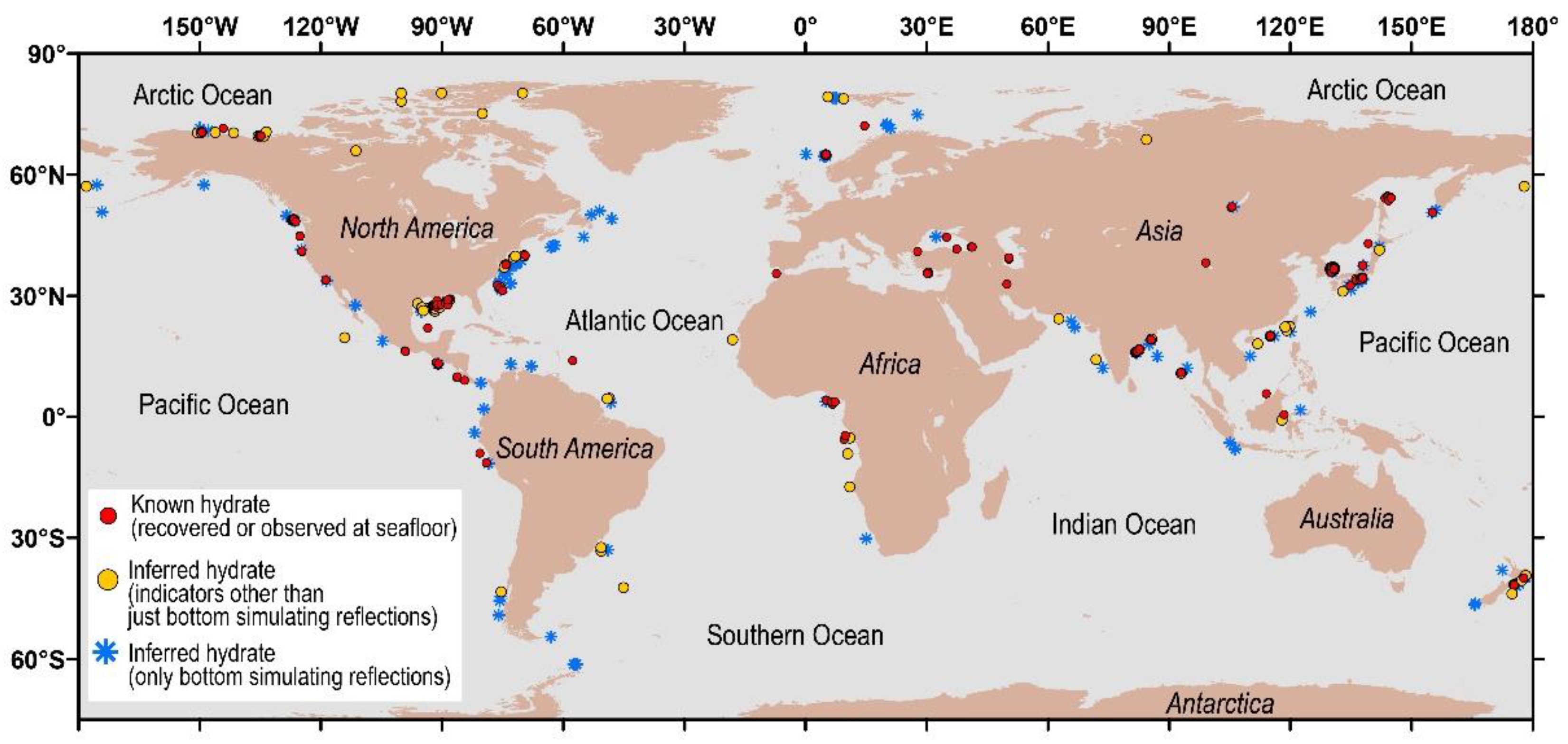
Figure 1. Distribution of main research areas of global natural gas hydrate [16].
Jmse 10 00645 g001
Figure 2. Gas hydrate drilling programs since the 1970s all over the world.
Jmse 10 00645 g002
Figure 3. Schematic diagram of main gas hydrate research areas in the north of South China Sea.
Jmse 10 00645 g003
Figure 4. Massive gas hydrate core sample and logging data from the same interval [37] (a) data from the pressure cored section of the W08 well; (b) X-ray image of pressure core; (c) Massive hydrate samples as recovered in a pressure core.
Jmse 10 00645 g004
Figure 5. Location of marine controlled-source electromagnetic survey of natural gas hydrate in Qiongdongnan Basin.
Jmse 10 00645 g005
Figure 6. Map of gas hydrate seismic surveys in the eastern Nankai Trough [47].
Jmse 10 00645 g006
Figure 7. Schematic diagram of natural gas hydrate exploration drill sites in the Ulleung Basin [51].
Jmse 10 00645 g007
Figure 8. Gas hydrate samples collected from UBGH1-10B-19H [52].
Jmse 10 00645 g008
Figure 9. Gas hydrate research areas established during NGHP-02 (Areas A,B,C and E) [58].
Jmse 10 00645 g009
Figure 10. Location map for the Blake Ridge region [59].
Jmse 10 00645 g010
Figure 11. Downhole log data from Hole 994D, 995B and 997B [60]. ((a) Downhole log data from Hole 994D, (b) Downhole log data from Hole 995B, (c) Downhole log data from Hole 997B).
Jmse 10 00645 g011
Figure 12. The 798 petroleum industry wells drilled in the northern Gulf of Mexico region, including the sites drilled during JIP Leg I and II [63].
Jmse 10 00645 g012
Figure 13. The northern Cascadia margin showing the region where gas hydrate is found [66].
Jmse 10 00645 g013
Figure 14. Gas hydrate resistivity laboratory test in the presence of sea water showing evolution resistivity during gas hydrate formation [76].
Jmse 10 00645 g014
Figure 15. Schematic of salt expulsion effect during hydrate formation.
Jmse 10 00645 g015
Figure 16. Relationship between resistivity and gas hydrate distribution in sediment [78].
Jmse 10 00645 g016
Figure 17. The resistivity and gas hydrate micro distribution in clean non-clay-bearing sediments.
Jmse 10 00645 g017
Figure 18. The resistivity relative to the nature of gas hydrate pore-space distribution in clay-bearing sediments.
Jmse 10 00645 g018
Figure 19. Simulation of electrical resistance of gas hydrate bearing sediments by fractal pore model [82]. (in (b,c), black stands for sediment particle, grey stands for pore water, white stands for gas hydrate).
Jmse 10 00645 g019
Figure 20. Frequency dispersion curves of complex resistivity parameters. (a) Amplitude and real part of the complex resistivity change with frequency; (b) Phase angle and imaginary part of complex resistivity change with frequency.
Jmse 10 00645 g020
Figure 21. Impedance spectra Nyquist diagram of the porous media containing gas hydrate.
Jmse 10 00645 g021
Figure 22. Free water and bound water variation trend under different pressures.
Jmse 10 00645 g022
Publisher’s Note: MDPI stays neutral with regard to jurisdictional claims in published maps and institutional affiliations.