Abstract
This paper proposed a concept prototype of the arm-claw-type manipulator with a general purpose support vessel for the rapid salvage of deep submergence vehicles, aircraft, satellites, etc. The key functions were realized, including object clamping, claw butting and locking, position and posture adjustment, awareness, positioning, and navigation. The prototype was successfully tested in a lake environment on a hollow and cylindrical object. The arm-claw-type manipulator is suitable for the rapid salvage of cylindrical objects in an underwater environment to minimize the clamping force and possible clamping damage on the object being salvaged. Four propeller thrusters with a symmetrical arrangement can be used for the adjustment of position and posture in underwater environments, to match the orientation of the object. Cameras capture the profile images of the underwater salvage object and can be used for posture adjustment, but in dark, deep-water environments, sonar can be used in the place of underwater cameras.
1. Introduction
With the development of marine transportation, the density of maritime transport increases and the scope of navigation extends continuously. Due to the complex navigable environment, marine safety accidents occur from time to time. However, due to the high costs, unpredictable environments, and time-consuming nature of salvage work, deep-sea rapid salvage is a big challenge [1].
Ecosystems in deep waters (>200 m) make up more than 90% of the biosphere; they connect shallow and deep-sea ecosystems, play a key role in nutrient regeneration, and providing harvestable fish resources [2]. Marine accidents lead to oil leaks from sunken ships, submersibles, aircraft, etc., which can pollute the marine ecosystem [3].
Deep-sea salvage technology is a key part of underwater engineering [4]. At present, research into deep-sea salvage techniques is still in its early stages, and underwater operations basically rely on underwater robots. Deep-sea salvage operations need dedicated devices for the deep sea environment [5].
In the 1960s, the United States Underwater Research Center (NUC) developed a salvage robot, and successfully conducted the salvage of sunken torpedoes at depths that ranged from 457 m to 884 m [6]. In the 1980s, Fu C., Xiang Z., and Li Z. designed a salvage manipulator, which was mounted on the Fish Eagle manned submersible, and successfully conducted the salvage of several sunken torpedoes [7,8,9]. Meng Q., Wang L. and Zhou et al. proposed a semi-buried mine salvage device [10]. Harbin Engineering University developed the “Micro Dragon” series of underwater robots with the functions of marine environment information collection, underwater object search, salvage, and life-saving aid [11]. Wang L. proposed an underwater carrier for large and heavy object salvage [12].
In 2013, Odyssey successfully used ROV with a basket to salvage 118 tons of silver ingots from a British merchant ship that was sunk during World War II at a depth of 4700 m in the southwest waters of Ireland; the ingots were valued at over USD 80 million [13]. Inflatable devices were used to salvage ship wrecks from water in the European research project “Surface System for Ship Recovery” (SuSy) [14].
In recent years, a series of research projects have been carried out by Dalian Maritime University and Huazhong University of Science and Technology, responding to the needs of deep-sea aircraft wreckage and black box salvage operations. In 2016, He F. proposed a prototype of a hydraulic expender for deep-sea salvage [15]. Dong Y. proposed a special device for grasping small objects, such as the black boxes of aircrafts, and tested it successfully in 2016 [16]. Zhang J. presented a flexible manipulator for marine research and rescue and salvage in 2021 [17]. In 2017, Sun X. designed a deep-sea hoisting tool, prototyped it, and conducted tests successfully [18]. In 2019, Zhang T. proposed a deep-sea salvage system that did not rely on any operational underwater vehicle to complete salvage operations, but it has not been tested yet [19].
In 2021, Dehkordi proposed a flexible manipulator with a robotic chain for underwater operations, and analyzed the dynamic response in water [20]. However, the concept was not suitable for deep water operations, particularly those involving large and heavy objects.
ROVs play the important role of search and detection in the salvage, and have the advantages of convenience and low cost [21]. The range of activity of an ROV is limited by the umbilical cable, but there are no limits on the amount of data it can collect, and it has high human–machine interaction [22]. AUVs do not rely on an umbilical cable and can be used in big areas, but data transmission is difficult.
The development trend of ROVs/AUVs produces devices that tend to be small in size and flexible in operation, and are not suitable for the salvage of large objects.
This paper proposed an arm-claw-type manipulator with a general support vessel for the deep-water salvage of large and heavy objects. Firstly, the requirement of the manipulators was analyzed; the manipulator concept was created and prototyped with regard to the functions of clamping, claw butting and locking, position and posture adjustment, awareness, positioning and navigation, etc. The operation modes are defined and analyzed in Section 2. Secondly, the rapid salvage system is introduced in Section 3, as well as the salvage procedures. Finally, lake tests were conducted successfully.
2. Design of the Salvage Manipulator
The objects to be salvaged generally include wrecks of deep submergence vehicles, aerospace carriers, and other large and heavy devices. Due to variation in their speeds and directions, objects fall down to the sea floor with an uncertain position and posture, some even into the mud and sand [23]. The operation environment is deep water that is not accessible to divers. The elements that affect the operation include the position and posture uncertainty, the underwater visibility, the sealing performance, the sea current, and the system reliability.
Generally, the posture, structure, and even damage of the object to be salvaged need to be considered in the design and operation of the manipulator. For submarine and other underwater carriers, it is necessary to know their framework structure and cabin layout to evaluate the stability and buoyancy of the underwater carriers during the salvage operation, and to make an accurate estimation of structural strength and the trend of further damage [24].
2.1. Requirements
The design requirements include general requirements, basic requirements, and additional requirements.
(1) General requirements:
The prototype should be suitable for fast salvage with a low cost and good maintainability, to support deep-water fast-salvage studies.
The prototype can be used with general purpose crane vessels, and also has good compatibility with recovery systems and umbilical cables.
(2) Basic requirements:
The object to be salvaged is assumed to be cylindrical, with a diameter of 2 m, a length of 10 m, and s weight of no more than 80 t.
The underwater operation depth is 1000 m.
The total weight of the salvage manipulator is no more than 2 t on land.
The manipulator should be adaptative to the posture of the object in the range of ±10° in the horizontal direction, as well as slight profile deformation.
(3) Additional requirements:
A simple and light structure is preferred, with easy assembly and disassembly, while ensuring that the strength and stiffness meet the minimum requirements for salvage work.
The manipulator should be self-balanced to ensure smooth operation.
Positioning and navigation capabilities are suitable for complex terrain and dark environments.
2.2. Functions
According to the design requirements, the salvage manipulator should have the functions of holding, claw butting, locking, and posture adjustment. As shown in Figure 1, the manipulator is composed of a lifting base, two arms for holding, and two claws (male and female) for butting and locking.
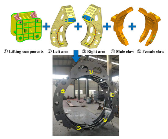
Figure 1.
The manipulator.
Two arms are fitted on the base; they have two hinges and can open and close using hydraulic cylinders. The two claws are retractable along arc guides on the arms.
The parameters of the manipulator are listed in Table 1.

Table 1.
Parameters of the manipulator.
2.2.1. Holding
Underwater operation manipulators are widely used for underwater exploration, particularly for sampling gripping.
Due to its simple structure, the manipulator’s clamping performance is good and the damage to the salvaged object is low. Meanwhile, the fabrication and maintenance costs are relatively low as well.
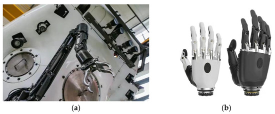
Figure 2.
Typical manipulators: (a) Clamp type and (b) Hand type.
The clamp type consists of two arms/fingers, which are driven by a motor or hydraulic cylinder, as shown in Figure 2a. It is widely used in production, such as in China’s YTO sub-assembly line robots, pipeline clamping machines, and heavy-duty forging manipulators. The hand type is a biomimetic design with five fingers, as shown in Figure 2b.
The clamp type structure is simple and reliable, compared with the hand type. The clamp type has significantly reduced maintenance and fabrication costs, and is particularly suitable for heavy-duty operations. The clamp type is widely used in marine engineering, such as in ROVs, AUVs, mining vehicles, trenchers, etc. A comparison of the two types of manipulators is summarized in Table 2.
Table 2.
Comparison of the two types of manipulators.
For the salvage manipulator prototype, considering the cylindrical geometry of the object to be salvaged, the clamp-type concept with two arc arms is adopted.
In Table 3, the parameters of the arc clamp-type manipulator are listed.
Table 3.
Circular arc clamp-type manipulator specification.
2.2.2. Butting and Locking
For holding reliability, butting and locking are required.
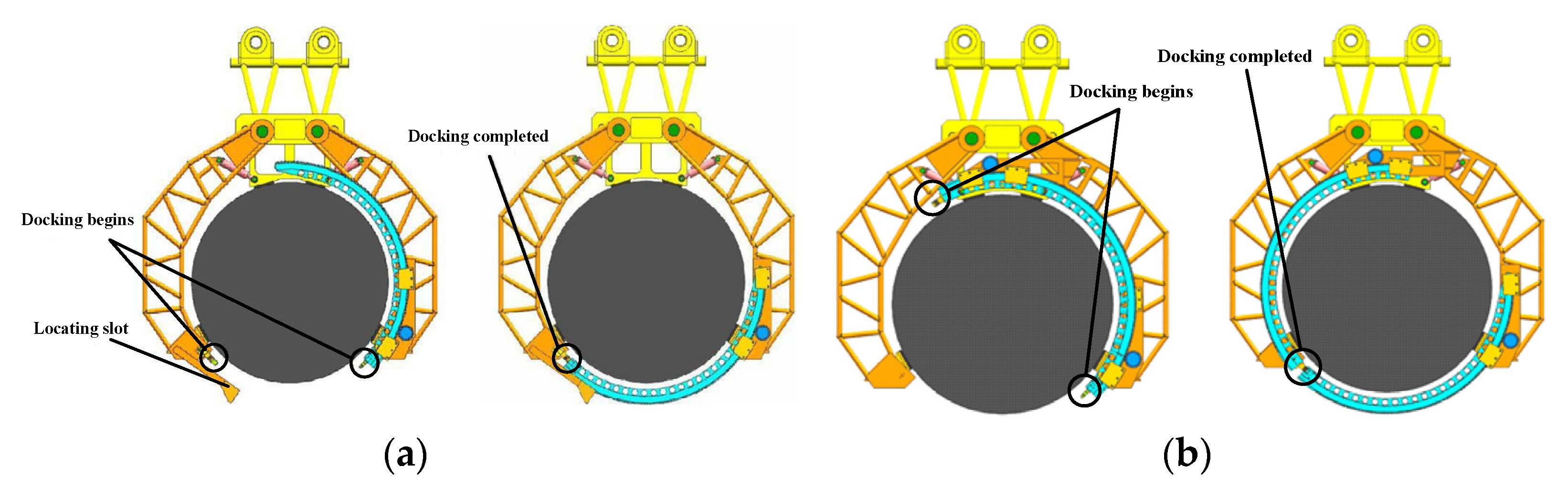
As shown in Figure 3, the salvage manipulator for underwater vehicles designed by Fu C [7] used ropes for salvage and proposed two strategies for butting and locking, which are single-rail docking and double-rail docking. Both strategies required an arc rail or rails to overcome the resistance of the subsea mud on butting and locking.
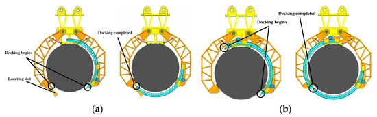
Figure 3.
Two strategies of the salvage manipulator for underwater vehicles. (a) Single-rail docking strategy and (b) Double-rail docking strategy.
The success of single-rail docking depends on the position accuracy of the claws. The docking fails when the claws cannot get into the right position, or the object is not a good cylindrical shape.
Compared with single-rail docking, double-rail docking is not affected by the rotation angle of the two claws. However, due to the long extension of the rail, the question of how to ensure docking accuracy after the rail penetrates the subsea mud was not considered in these two docking strategies.
In the current research, the male and female claws extend simultaneously, and the docking and locking of the two claws are completed at the bottom of the manipulator. A comparison with the single-rail and double-rail strategies is given in Table 4.
Table 4.
Comparison between rail docking and bottom docking.
The concept of the plug-in lock is adopted in this docking and locking mechanism; one side is the male claw and the other side is the female claw. After the arms are closed, the male claw and the female claw are driven by hydraulic cylinders along the arc rails and stretch out at the bottom of the manipulator until the butting and locking are finished.
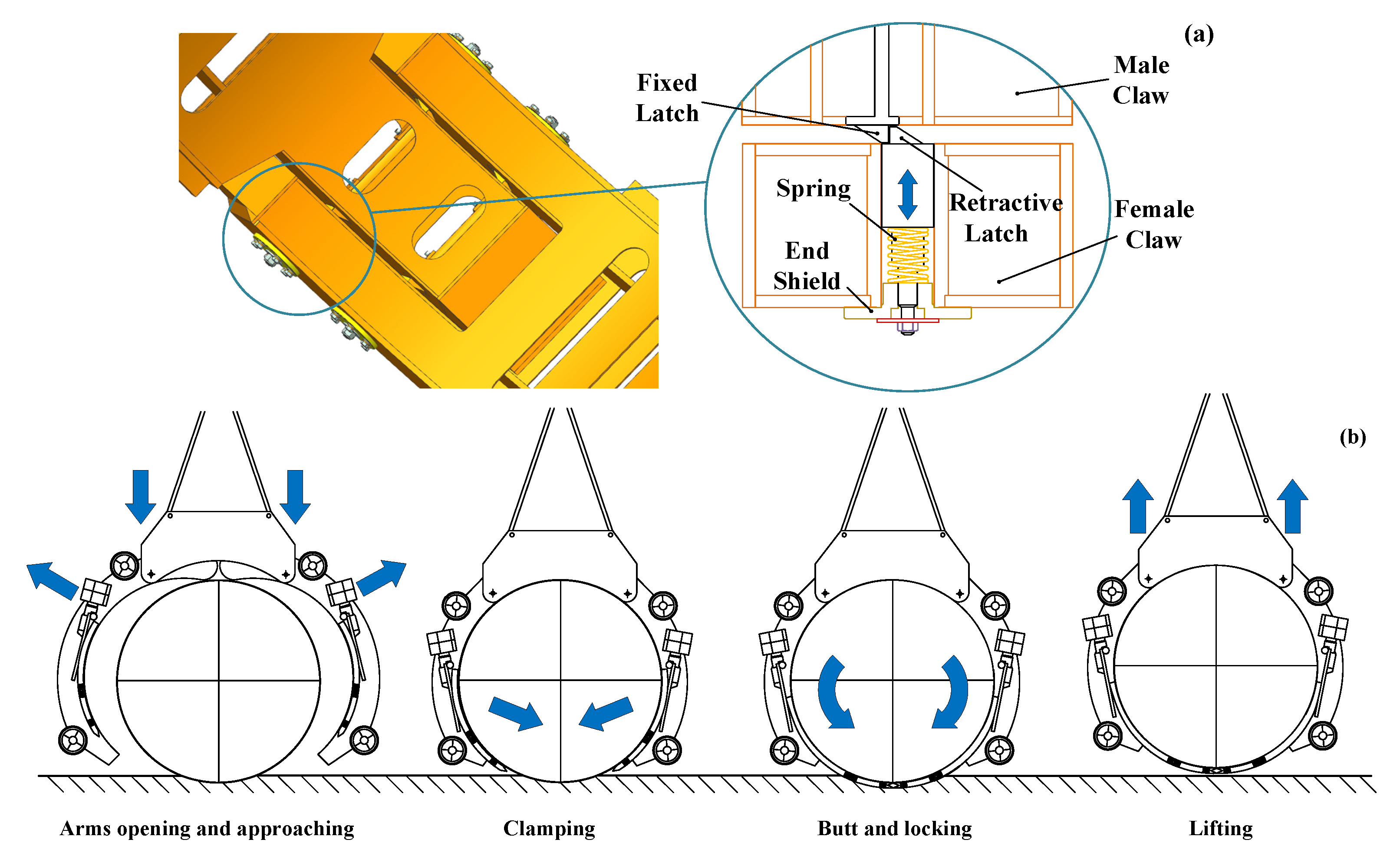
The female claw is equipped with a spring loaded retractive latch and the male claw is equipped with a fixed latch.
The retractive latch and fixed latch are as shown in the Figure 4a. When the fixed latch contacts the retractive latch, the retractive latch can be pressed down along the bevel of the fixed latch. When the male and female claws move to the designated positions, the retractive latch pops out again and the male and female claws are butted and locked. Rotating the nut in the same picture can make the retractive latch retract for unlocking purposes.
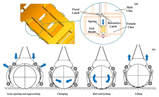
Figure 4.
Working principle and process of the butting and locking mechanism: (a) Locking and unlocking principle and (b) Working principle of Manipulator.
To ensure the success of butting and locking, the synchronous movement of hydraulic cylinders is required and tested in this research. The hydraulic system is as shown in Figure 5a, which consists of male and female claws, hydraulic cylinders, safety valves, and an oil supply system. The hydraulic cylinder parameters are listed in Table 5.
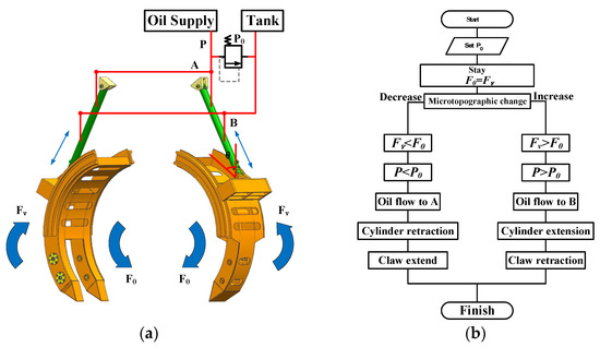
Figure 5.
Synchronous motion of claws: (a) Hydraulic system and (b) Control flow chart.
Table 5.
Claw tip parameters.
The control flow chart is as shown in Figure 5b. The male and female claws stretch out along the arc rails to complete the butting and locking and draw back after unlocking.
Two typical shapes of claw tips are available, as shown in Figure 6a (Conical tip) and Figure 6b (Wedge tip). The conical tip is suitable for excavating soft soil and is more efficient than the wedge tip. The life-cycle of the wedge tip is better than the conical one. The wedge tip, which is welded in the front of the male and female claws, can be used for hard soil.
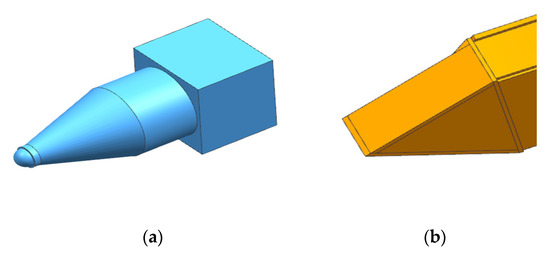
Figure 6.
Typical claw tips: (a) Conical tip, (b) Wedge tip.
The wedge tip is adopted in the current design of the claws. Hydraulic cylinders are controlled by solenoid valves, and the speed can be set during operation. The claw tip parameters are listed in Table 5.
2.2.3. Posture and Position Adjustment
The manipulator’s underwater posture and position can be adjusted by thrusters, so as to align with the object’s orientation. The adjustment controlled manually by the operator on the support vessel, according to the feedback images provided by the camera or sonar on the manipulator.
Two typical thrusters are available: the water jet thruster and the propeller thruster. The water jet thruster is suitable for shallow-water operations. The propeller type is a better option for salvage manipulators used in deep water.
In the current manipulator design, the DC brushless motor-driven channel paddle is adopted for the thrusters.
The channel paddle thrusters can be operated both forward and backward.
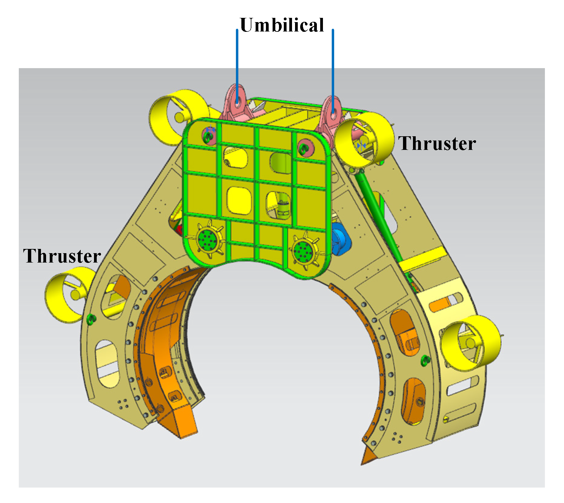
Four thrusters are symmetrically arranged outside of the manipulator, as shown in Figure 7. The manipulator with four thrusters is as shown in Figure 8. The power supply for the motor is 500 VDC and 15 kw, and the power supply for the control and PWM signal is 24 V and 2.5 kw. The controller receives the command from the electronic cabin, then generates four different voltages and PWM speed signals through four underwater cables for four thrusters, respectively. The controller communicates with the surface control computer in real time via an RS-485 interface.
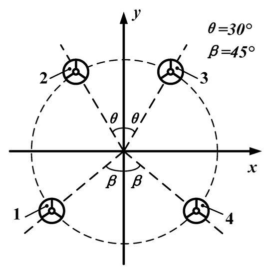
Figure 7.
Thruster arrangement diagram.
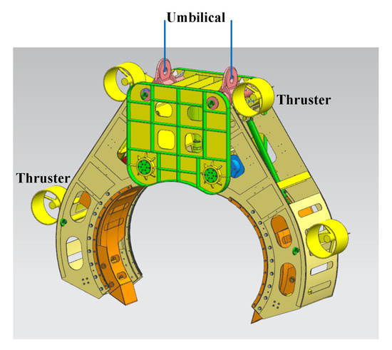
Figure 8.
The manipulator with thrusters.
The relations between thruster output and manipulator motion are listed in Table 6.
Table 6.
Relations between the thruster output and the motion of the manipulator.
Thrust is generated by four hydraulic propellers installed around the manipulator to realize the short-distance movement function, as shown in Figure 8. The thruster specification is listed in Table 7.
Table 7.
Thruster specification.
2.3. Additional Functions
Additional functions are required to support the operation, including awareness, positioning, and navigation.
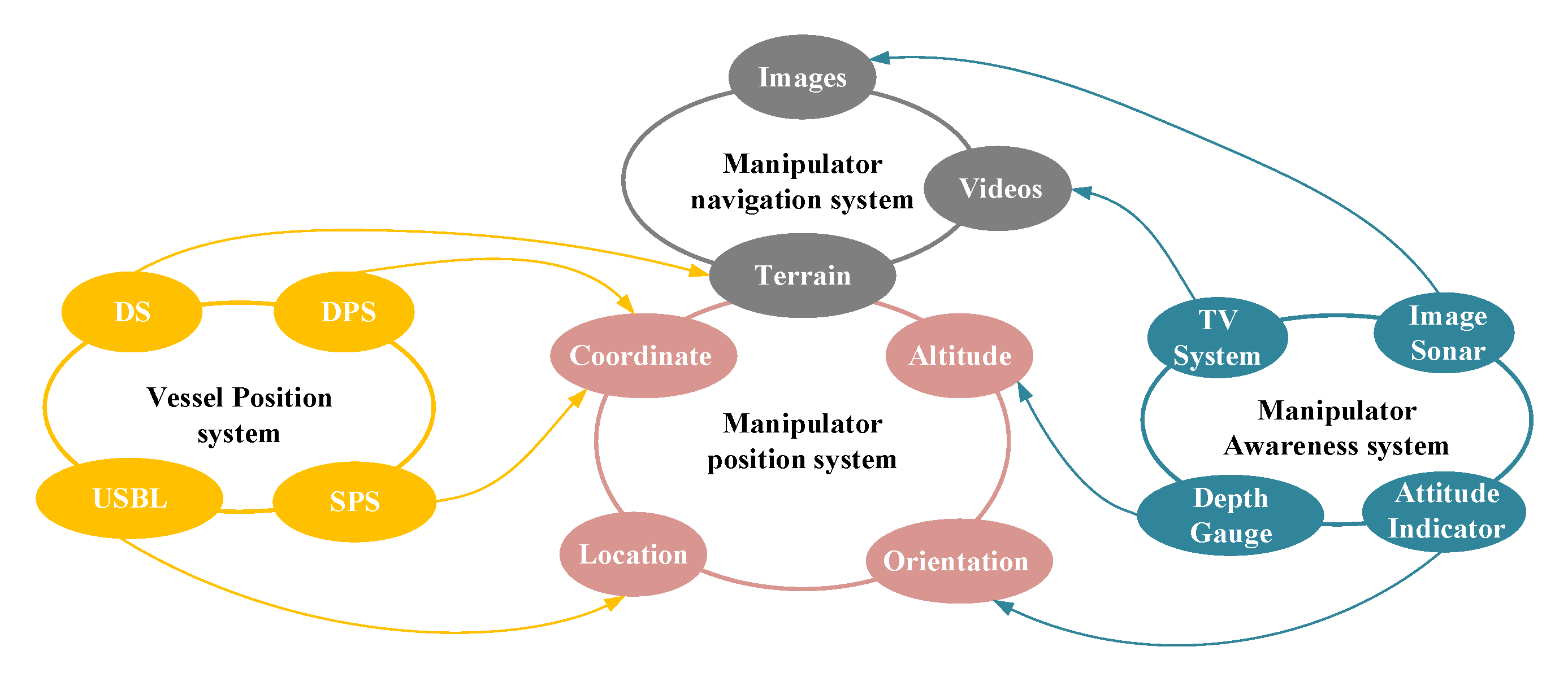
The awareness system and positioning and navigation system are as shown in Figure 9. The support vessel positioning system includes the dynamic positioning system (DPS), detection system (DS), ship positioning system (SPS), and ultra-short baseline (USBL), as shown on the left of Figure 9. DPS and SPS detect the position of the vessel in selected coordinates, and USBL can detect the position of the manipulator relative to the vessel.

Figure 9.
Awareness system and positioning and navigation system.
The awareness system includes the TV system, image sonar, attitude indicator, and depth gauge, as shown on the right of Figure 9. The TV system provides real-time videos and images to the operator. The image sonar is used to detect the terrain beyond the range of vision of the TV system to ensure the safety of the manipulator in the launch and underwater operation. The attitude indicator and depth gauge relay altitude and depth to the positioning and navigation system, to control the motion direction and posture adjustment of the manipulator.
The positioning and navigation system is as shown in the middle of Figure 9. These functions are realized according to the feedback of the awareness system and vessel positioning system.
2.4. Design Process
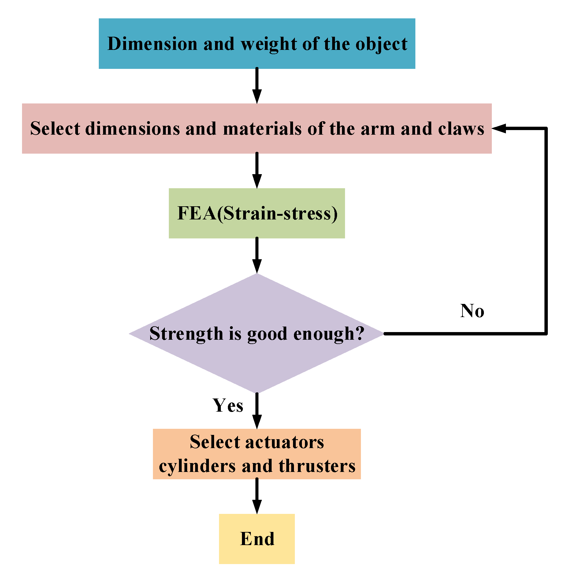
The design process is as shown in Figure 10. According to the given dimension and weight of the object, select the dimensions and material of the arm and claws, and create the 3D model for FEA. If the strength is not sufficient, change the dimensions or material of the arm and claws and redo FEA until the strength is sufficient for the given load. After the dimensions and materials of the arm and claws are determined, select the actuators, including cylinders and thrusters.
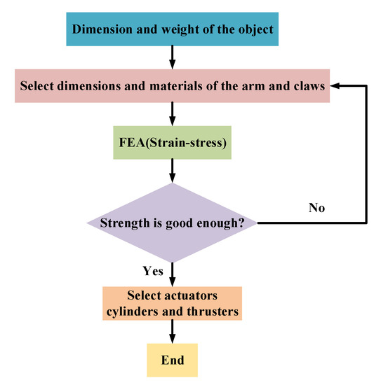
Figure 10.
Design flowchart of the manipulator.
2.5. System Composition
The system composition is as shown in Figure 11. It is composed of the lifting assembly, clamping assembly, butting and locking mechanism, thrusters, electrical system, awareness system, hydraulic system, and positioning and navigation system.
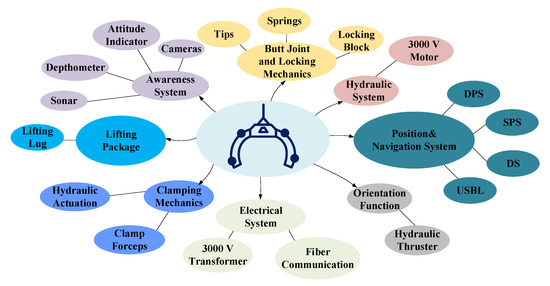
Figure 11.
The manipulator assembly.
2.5.1. Parameters
The manipulator parameters are listed in Table 8. The total weight is around 3 metric tons in the water and the operation depth is up to 1000 m. The power supply voltage is 3000 V, and the power is 70 kW. The parameters of the manipulator are given in Table 8.
Table 8.
Manipulator parameters.
2.5.2. Operation Modes
Two operation modes are available for the salvage process: seawater mode and seafloor mode.
(1) Seawater mode
Seawater mode is for the launch and recovery process of the manipulator. The operator monitors the position and orientation of the manipulator on the support vessel and adjusts the position and orientation to ensure that launch and recovery process is smooth and successful.
(2) Seafloor mode
Sea-floor mode is used during clamping, claw butting and locking, and position and posture adjustment. When the manipulator is in the right position, the two arms are closed to hold the object reliably, and two claws stretch out for butting and locking to ensure the object is safely held by the manipulator. After the claw locking is finished, the lifting system starts to move the object out of the water.
2.5.3. Operation Process
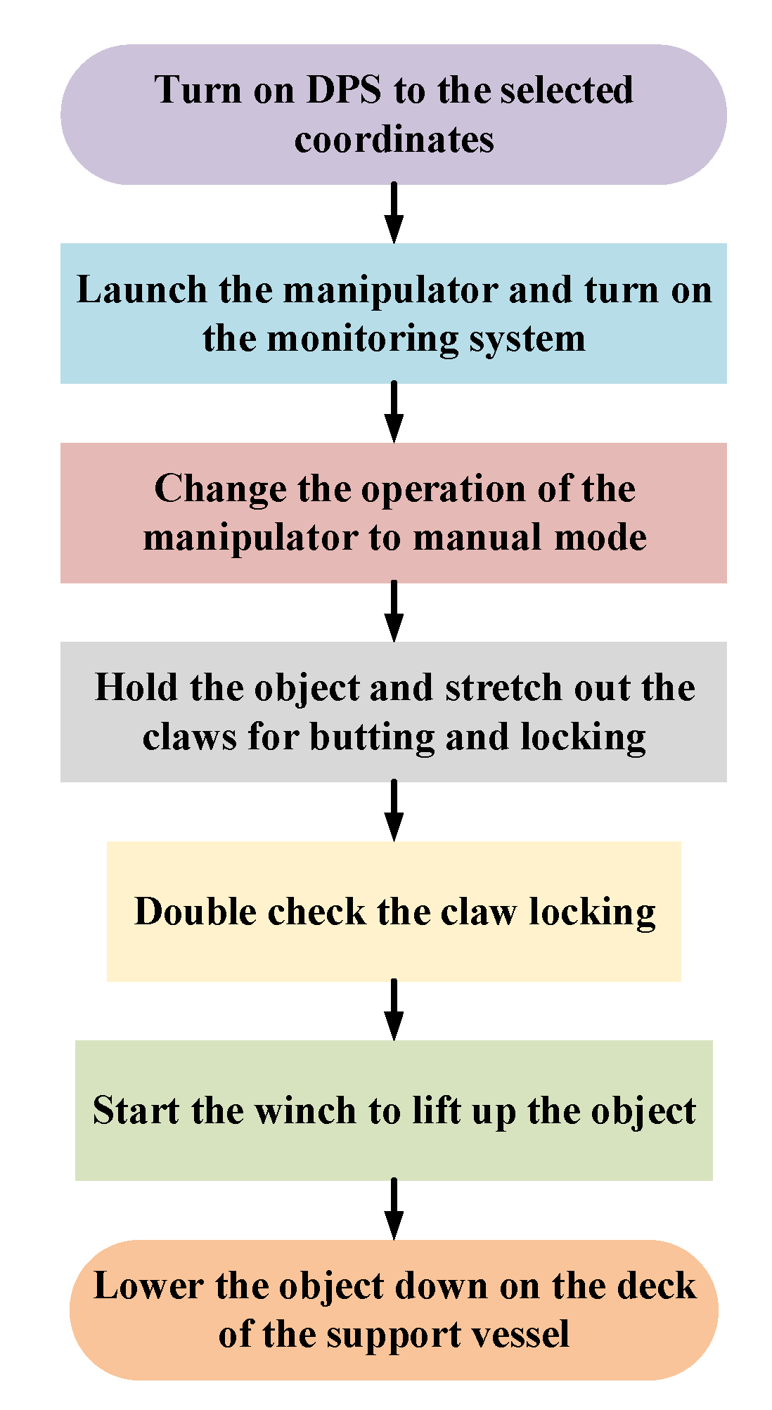
The operation process of the manipulator is as shown Figure 12.
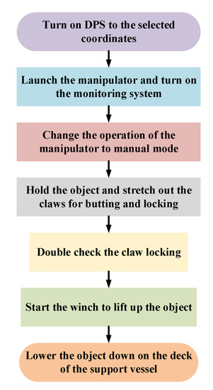
Figure 12.
Flowchart of the manipulator operation process.
The operation of the manipulator comprises seven steps:
Step 1: Turn on the DPS of the support vessel to the selected coordinates before the manipulator is launched.
Step 2: Launch the manipulator and turn on the monitoring system.
Step 3: After launching the manipulator into the right position, change the operation of the manipulator to manual mode.
Step 4: Close the two arms to hold the object on both sides and stretch out the claws for butting and locking.
Step 5: Double check the claw-locking state before recovery.
Step 6: Start the winch to lift the object up with a constant speed, and monitor the whole process continuously through the monitoring system.
Step 7: Lift the object out of the water and lower it down onto the deck of the support vessel.
3. Salvage System
The manipulator needs to work with the general-purpose support vessel with the crane and umbilical system. The crane is used during the manipulator launch, and recovery and object lifting. The umbilical system provides the power supply and signal transmission. The system is as shown in Figure 13.
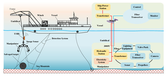
Figure 13.
The rapid salvage system (Left); the control system (Right).
As shown in Figure 13, the rapid salvage system consists of the manipulator, the umbilical system, and the support vessel.
The manipulator under water and the support vessel on the sea surface are connected by the umbilical cable. The monitoring system is installed on the manipulator to capture underwater images and send them back to the support vessel, so that operator can make timely decisions for position adjustment. An ultra-short baseline (USBL) system is installed on the umbilical cable below the support vessel, which relays the real-time position of the manipulator to the support vessel. The surveying system on the support vessel can obtain the topographic information of the seafloor.
This vessel supplies the power of 3000 V to the manipulator through a transformer to the hydraulic station and electrical system installed on the manipulator. The vessel communicates with the manipulator via the fiber-optic cable in the umbilical system for real-time monitoring and control.
The support vessel is a submarine operation mother ship. The support vessel is 44 m in length, 12.4 m in width, and 6.3 m in height, with a full load displacement of 300 tons.
Figure 14 shows the manipulator launching from the crane of the support vessel during the test.
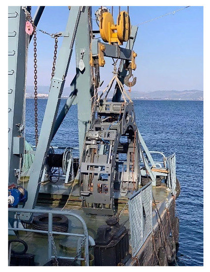
Figure 14.
Launch of the manipulator.
4. Tests
The tests were conducted in a lake with depth of 150 m at the test point. The positioning and navigation system, clamping system, claw butting and locking mechanism, position and posture adjustment, and awareness system were fully tested. The object to be salvaged in these tests was supposed to be a hollow cylinder with a diameter of 2.0 m and a weight of 3.0 tons on land.
4.1. Lake Test
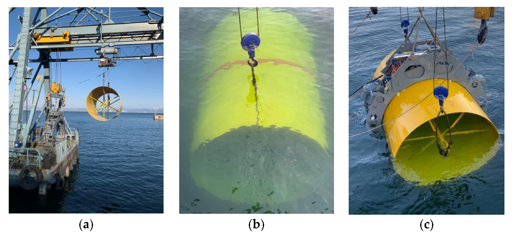
The lake test of the prototype is shown in Figure 15. The cylindrical object was launched by the crane at the test point, as shown in Figure 15a. The object was dipped into the water, as shown in Figure 15b. According to the manipulator operation process detailed in Section 2.5.3, the manipulator was launched and picked up the object. After the manipulator held the object reliably, the object was lifted out of the water, as shown in Figure 15c.

Figure 15.
Lake test of the manipulator prototype: (a) Launch the object at the test point, (b) The object wad dipped into the water and (c) Lift the object out of the water.
4.2. Test Results
The results of the lake test are summarized below:
(1) Clamping test
The clamping test of the manipulator was carried out in the lake test, as shown in Figure 16. The manipulator approached the object with a large posture error, as shown in Figure 16a; after posture adjustment, the manipulator aligned with the object very well and touched the object on the top, as shown in Figure 16b; the two arms closed to hold the object well, as shown in Figure 16c.
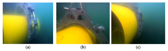
Figure 16.
Clamping test of the manipulator: (a) Close to the object, (b) Posture adjustment and (c) Hold the object.
The clamping test was repeated 10 times and every test was successful.
(2) Butting and locking test
Butting and locking tests were conducted in the meantime, as shown in Figure 17. After the arms closed, the claw tips stretched out of the arm, as shown in Figure 17a. The claw tips further stretched out to the bottom of the object, as shown in Figure 17b. As the butting and locking happened beneath the object, no further images could be captured.
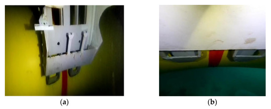
Figure 17.
Butting and locking test: (a) Claw tips stretched out and (b) Claw tips further stretched out to the bottom of the object.
(3) Awareness system and positioning navigation system
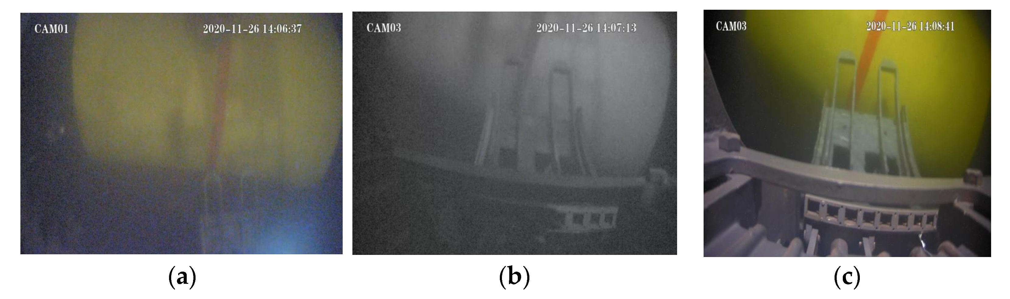
During the test, the underwater cameras captured the object profile with the claw tip on one side, as shown in Figure 18a; when the cameras moved closer to the object, the object image was clearer and the posture error of the manipulator can be seen, as shown in Figure 18b,c. If the posture error is too large, such as more than 30°, the posture should be adjusted before advancing further towards the object, to ensure the object successfully enters the opening between the two arms of the manipulator. In the test, this situation did not arise. The manipulator also approached the object with a posture error, as shown in Figure 16a. At this time, the posture was adjusted to minimize the posture error before the manipulator touched the object. After the posture adjustment, the manipulator was further lowered down until touching the top of the object, as shown in Figure 16b. The tests of the awareness system and the positioning and navigation system were successful.
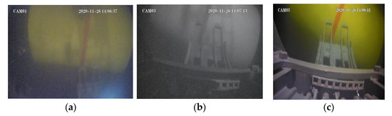
Figure 18.
Images captured by cameras when the manipulator approached the object: (a) Object founded, (b) Approaching the object and (c) Judgement of attitude adjustment error by image.
5. Conclusions
This paper proposed a concept prototype of an arm-claw-type manipulator with a general-purpose support vessel for the rapid salvage of deep submergence vehicles, aircraft, satellites, etc. According to the requirements of these salvage operations, the key functions were realized, including object clamping, claw butting and locking, position and posture adjustment, awareness, positioning, and navigation. The prototype was successfully tested in a lake environment, salvaging a hollow and cylindrical object. The following conclusions can be drawn:
- (1)
- The arm-claw-type manipulator is suitable for the rapid salvage of cylindrical objects in an underwater environment, as it minimizes clamping force and possible clamping damage on the object to be salvaged.
- (2)
- The claw butting and locking mechanism works well and reliably in an underwater environment.
- (3)
- Four propeller thrusters with a symmetrical arrangement can be used for position and posture adjustment in an underwater environment in the given range, to align with the orientation of the object to be salvaged.
- (4)
- The cameras captured the profile images of the underwater salvage object; these images can be used to estimate posture error, and to adjust posture to match the orientation of the object. In a dark, deep-water environment, sonar can be used in the place of underwater cameras.
The manipulator can be used for non-cylinder geometries, but the strength and dimensions of both the object and the manipulator need to be recalculated, as does the stability of lifting.
Further work for this deep-water salvage manipulator includes the mechanical analysis and FEA of the manipulator (Part B); latch geometry optimization of the male and female claws (Part C); analysis of the influence of eddy-excited vibration on stability during lifting (Part D), etc.
Author Contributions
Conceptualization, F.Y. and Y.N.; Methodology, Y.N.; Writing—original draft preparation, Y.N. and F.Y.; Writing—Review and editing, F.L., S.Y., L.W., C.L., P.W., M.L. and Z.L.; Validation, L.W., F.L. and S.Y.; Supervision L.W.; Funding acquisition, F.Y. All authors have read and agreed to the published version of the manuscript.
Funding
This research was funded by National Natural Science Foundation of China (52001089); Heilongjiang Provincial Natural Science Foundation of China (LH2021E046); Fundamental Research Funds for the Central Universities (3072021CFT0701); China Postdoctoral Science Foundation (2020M670889).
Acknowledgments
The authors gratefully acknowledge the financial support from National Natural Science Foundation of China (52001089); Heilongjiang Provincial Natural Science Foundation of China (LH2021E046); Fundamental Research Funds for the Central Universities (3072021CFT0701); China Postdoctoral Science Foundation (2020M670889).
Conflicts of Interest
All the authors have read and approved this version of the article, and due care has been taken to ensure the integrity of the work. The authors declare no conflict of interest.
Abbreviations
| ROV | Remote Operated Vehicle |
| AUV | Autonomous Underwater Vehicle |
| DPS | Dynamic Positioning System |
| SPS | Ship Positioning System |
| DS | Detection System |
| USBL | Ultra-Short Baseline |
References
- Yan, Y.; Jin, H.; Zhang, Y.; Wang, J.; Guo, J. Statistical analysis of typical ship accidents in past 4 years and review of salvage equipment in China. In Proceedings of the 5th International Conference on Transportation Information and Safety (ICTIS), Liverpool, UK, 14–17 July 2019. [Google Scholar] [CrossRef]
- Drazen, J.C.; Smith, C.R.; Gjerde, K.M.; Haddock, S.H.D.; Carter, G.S.; Choy, C.A.; Clark, M.R.; Dutrieux, P.; Goetze, E.; Hauton, C.; et al. Opinion: Midwater ecosystems must be considered when evaluating environmental risks of deep-sea mining. Proc. Natl. Acad. Sci. USA 2020, 117, 17455–17460. [Google Scholar] [CrossRef] [PubMed]
- Lee, M.; Jung, J.Y.; Park, K.C.; Choi, S.H. Environmental and economic loss analyses of the oil discharge from shipwreck for salvage planning. Mar. Pollut. Bull. 2020, 155, 111142. [Google Scholar] [CrossRef] [PubMed]
- Dean, M.S. Salvage Operations; Springer: Berlin/Heidelberg, Germany, 2016; Volume 158, pp. 985–1066. [Google Scholar] [CrossRef]
- Wang, Z. Current development of rescue and salvage equipments. J. Mech. Eng. 2013, 49, 91–100. [Google Scholar] [CrossRef]
- Kohnen, W. Human exploration of the deep seas: Fifty years and the inspiration continues. Mar. Technol. Soc. J. 2009, 43, 42–62. [Google Scholar] [CrossRef]
- Fu, C. Design and Experimental Study of Salvage Manipulator for Underwater Vehicle. Master’s Thesis, Harbin Engineering University, Harbin, China, 2016. [Google Scholar]
- Xiang, Z.; Mao, J. Manipulator Development for Manned Underwater Salvage Vehicle “The Cormorant”. Ocean Technol. 1990, 1, 12–17. [Google Scholar]
- Li, Z. Design of underwater clamp fixture for salvaging target torpedo. Mech. Eng. 1991, 3, 9–10, 22. [Google Scholar]
- Li, G.; Wang, L.; Meng, Q. A Salvaging Apparatus for Underwater Half-buried Torpedo. J. Harbin Eng. Univ. 1999, 5, 18–22. [Google Scholar]
- Zhang, Z.; Wang, L. Design and research on the two-joint mating system of underwater vehicle. China Ocean Eng. 2013, 3, 111–120. [Google Scholar] [CrossRef]
- Zhou, D. Research on Key Technology of Half-Bury-Torpedo Device. Ph.D. Thesis, Harbin Engineering University, Harbin, China, 2006. [Google Scholar]
- The Company History of Odyssey Marine Exploration. Available online: https://www.odysseymarine.com/history (accessed on 17 January 2022).
- Ilias, Z.; Elias, C.; Nicholas, T. An innovative ship salvage concept and its effect on the hull structural response. J. Mar. Eng. Technol. 2018, 19, 266–277. [Google Scholar] [CrossRef]
- He, F.; Qiu, L.; Yu, F. A new type of underwater salvage dilator with seawater hydraulic drive. Appl. Mech. Mater. 2014, 620, 44–47. [Google Scholar] [CrossRef]
- Yang, D. The Research of Black Box Dedicated Grab Tool in Deep Sea. Master’s Thesis, Dalian Maritime University, Dalian, China, 2016. [Google Scholar]
- Zhang, J.; Chen, Y.; Gong, Y. Dynamic Model and Analysis of Soft Manipulator Facing Underwater Complex Environment. In Proceedings of the 6th International Conference on Automation, Control and Robotics Engineering (CACRE), Dalian, China, 15–17 July 2019. [Google Scholar] [CrossRef]
- Sun, X. The Design and Experimental Research of the Deep-Sea Hoisting Tool. Master’s Thesis, Dalian Maritime University, Dalian, China, 2017. [Google Scholar]
- Zhang, T.; Qin, S.; Wang, X.; Tang, J. Deep-sea search and recovery: With and without operating an underwater vehicle. Ocean Sci. Discuss. 2018, 5, 1–16. [Google Scholar] [CrossRef] [Green Version]
- Dehkordi, S.F. Dynamic analysis of flexible-link manipulator in underwater applications using Gibbs-Appell formulations. Ocean Eng. 2021, 241, 110057. [Google Scholar] [CrossRef]
- Wei, R. Research on Development Tendency and Prospect for Underwater Robot. Mod. Manuf. Technol. Eq. 2018, 2, 175–176. [Google Scholar] [CrossRef]
- Liu, L.; Wu, Z. Analysis of small underwater robots in the application of underwater rescue and salvage. China Water Transp. Sci. Technol. Waterw. 2021, 1, 50–54. [Google Scholar] [CrossRef]
- Chen, Y. Research on Deep-sea Wreck Equipment Search and Salvage System and its Key Technologies. Ph.D. Thesis, Harbin Engineering University, Harbin, China, 2019. [Google Scholar] [CrossRef]
- Pan, D.; Zhou, Z.; Sun, Y.; Zhao, K.; Xu, M. Simulation and Research on Righting a Damaged Ship Based on GHS Software. In Proceedings of the 6th International Conference on Control, Automation and Robotics (ICCAR), Singapore, 20–23 April 2020. [Google Scholar] [CrossRef]


Publisher’s Note: MDPI stays neutral with regard to jurisdictional claims in published maps and institutional affiliations. |
© 2022 by the authors. Licensee MDPI, Basel, Switzerland. This article is an open access article distributed under the terms and conditions of the Creative Commons Attribution (CC BY) license (https://creativecommons.org/licenses/by/4.0/).