Article

Stability Analysis of a TLP with Inclined Tension Legs under Different Marine Survival Conditions

1
School of Mechanics and Engineering Science, Shanghai University, Shanghai 200444, China
2
Shandong Taikai Power Engineering Co., Ltd., Taian 271000, China
3
Shanghai Institute of Applied Mathematics and Mechanics, Shanghai University, Shanghai 200444, China
*
Author to whom correspondence should be addressed.
J. Mar. Sci. Eng. 2022, 10(8), 1058; https://doi.org/10.3390/jmse10081058
Submission received: 27 June 2022 / Revised: 25 July 2022 / Accepted: 29 July 2022 / Published: 31 July 2022
(This article belongs to the Special Issue Hydrodynamics of Offshore Structures)

Abstract

:
To verify that inclined tension legs can improve the stability of the tension leg platform, this paper established the dynamic equation of a tension leg platform (TLP) under marine environmental loads by using the modified Morrison equation considering the influence of ocean currents on wave forces. Additionally, the velocity and acceleration of random wave water particles were simulated via the JONSWAP spectrum. In addition, a three-dimensional model of a tension leg platform with inclined tension legs was established by AQWA, and its dynamic responses under variable survival conditions were compared and analyzed. The results showed that the surge and heave were more sensitive to the sea current, while the pitch was more sensitive to the wind. There is a significant difference in tendon tensions between the atypical TLP with inclined tension legs established in this study and the typical International Ship and Offshore Structures Committee (ISSC) TLP.

1. Introduction

Since the floating wind turbine was proposed [1], scholars have carried out in-depth studies from multiple perspectives and proposed various forms of floating wind turbines, such as the semi-submersible, Spar, and tension leg platform (TLP) forms. Among them, the TLP originated from the floating platform in offshore oil field exploitation and was proposed by Professor J.R.O. Marsh of the United States in 1954 [2]. The TLP achieves superior stability in both vertical and horizontal directions through its buoyancy and the pretension of the mooring system [3]. Compared with other floating platforms, the TLP shows better heave, surge and sway responses and motion characteristics at water depths of 300~1500 m, but its mooring system is more complex, and its installation cost is higher than that of the other two types. Moreover, due to the tendons being affected by the tension and sea current, the frequency of the mooring system and the superstructure are prone to coupled resonance. Therefore, it is crucial to study the dynamic characteristics of the TLP floating foundation to avoid significant losses [4].
The TLP is a semirigid and semicompliant nonlinear dynamic system. Due to the pretension provided by the mooring system, the inertia force generated by the platform can offset part of the environmental load effect, thus allowing better stability. Its natural period is far from the frequency where the wave energy is concentrated, thus avoiding the resonant response of the TLP to the primary wave frequency and making the platform as free from structural failure as possible. For decades, scholars have summarized the research emphases of TLPs, including research on the dynamic response of TLPs under the action of complex environmental loads, structural optimization, and research on mooring systems. At first, scholars proposed a relatively simple dynamic model of TLP by using linear wave theory, the Morrison equation and three-dimensional potential flow theory, etc., without considering the coupling problem of various degrees of freedom. Pualing et al. [5,6] established three-degree-of-freedom (3-DoF) and 6-DoF models of the TLP, calculating the wave load by the Morrison equation, and Mercier et al. [7] proposed a basic formula of the platform in a heave direction. Their mathematical models laid a specific foundation for follow-up research. Furthermore, scholars put forward a gradually improved dynamic balance model with coupling degrees of freedom and considered the interaction interference between the tension leg and floating platform [8,9]. To more accurately describe the motion characteristics of the TLP in the marine environment, the tension leg was simplified as a massless spring model, a lumped mass model or a nonlinear beam model. The 6-DoF stiffness matrix and the coupled nonlinear motion equation and boundary conditions of TLP were, respectively, derived by the unit displacement method and Hamiltonian principle [10,11,12,13]. Considering the coupling effect, scholars have studied the dynamic responses of TLPs under different waves, proposed new methods for calculating the recovery stiffness and considered the simultaneous action of multiple nonlinear loads, diffraction problems and subsidence effects. For instance, by deducing the mass matrix, coupled stiffness matrix, damping matrix and external load of the vibration differential equation, Gu et al. [14] investigated the coupled responses of TLPs under the action of random waves. By distinguishing the horizontal low-frequency motion caused by second-order wave excitation and the vertical motion with higher frequency caused by first-order wave force, Senjanovic et al. [15] deduced a more accurate tangent stiffness and considered the sinking effect in the dynamic equation. Wang et al. [16] used a full-field quadratic transfer function (QTF) to calculate second-order wave forces. Chandrasekaran et al. [17] analyzed the water particle movement based on Stokes theory and estimated the wave load acting on the tension leg by using the improved Morrison equation. To investigate the statistical characteristics of the air gap of the TLP, Lim et al. [18] established a second-order Volterra series for wave height around the platform by using the second-order potential flow theory and solved it with the spectrum and the eigenvalue problem of the transfer function of the frequency domain. Mazarakos et al. [19] analyzed the coupled hydroaeroelastic problem for a TLP with multiple vertical truncated cylinders, and solved the hydrodynamic problem by combining the physical idea of multiple scattering and the method of matched axisymmetric eigenfunction expansions. In summary, this paper considers the Morrison equation combined with a random wave spectrum to calculate nonlinear wave forces and simultaneously applies random wind loads and linear ocean current loads to the structure.
To establish more accurate models and cope with highly complex interactions, scholars conducted simulations through FAST, HAWC2, SIMO, SESAM, AQWA, etc. [20,21,22,23]. Sclavounos et al. [24] proposed two low weight, motion resistant stiff floating wind turbine concepts and modeled rigid body dynamics of it by using FAST. Moreover, multiple complex coupling problems can be well solved with the numerical technique. The hydrodynamic responses of the floating platform, such as 6-DoF motion and mooring tension, can be obtained, and the operating load of the floating wind turbine can be evaluated by this means [25,26,27]. Notably, AQWA, a comprehensive simulation tool, plays a significant role in the field of floating body analysis. Over the past decade, AQWA has been used to study the hydrodynamic characteristics of different types of floating foundations. Ghafari et al. [28] established a three-dimensional model using radiation/diffraction theories and the Morrison equation with AQWA. Yang et al. [29] combined the user-defined dynamic library link (DLL) with AQWA through AeroDyn to simulate the wind, wave and current loads of the multibody floating wind turbine (FWT) platform. Sun et al. [30] further verified the prediction accuracy of the AQWA–Aerodyn coupling framework for the floating wind turbine coupling response by comparing it with the calculation results of FAST. Ma et al. [31] calculated low-frequency surge motion in the time domain using AQWA. Ren et al. [32] calculated the hydrodynamic parameters and motion responses of a TLP floating offshore wind turbine (FOWT) by the hydrodynamic analysis software WAMIT and AQWA. Thanks to the usefulness and credibility of AQWA verified by published papers, we chose this software to establish a finite element model and analyze the dynamic characteristics of TLP.
Regarding infrastructure innovation, scholars mainly altered the structure of the floating platform or added other components to tension legs without considering the alteration of the tension leg itself. Ma et al. [33] experimentally and numerically studied the multibody dynamic coupling responses of a new type of TLP. Rao et al. [34] proposed a tension leg platform with a tension base, which reduced the in-plane motion responses by connecting the base in series on the tendons. Adam et al. [35] proposed a novel floating wind turbine GICON®-Tension Leg Platform (TLP). Walia et al. [36] conducted a free attenuation test of the scale model for TLP and compared its natural frequency results with those of GICON®-TLP. Han et al. [37] proposed an underwater tension leg platform (STLP) for medium water depths ranging from 70 to 150 m. Ren et al. [38] proposed a new concept of combining TLP with a buoyancy wave energy converter, namely, TWWC TLP–WT–WEC Combination (TWWC). Two floater concepts coupled with the wind turbine in water depths of 10–200 m were conducted to identify differences in those two stability methods by Wayman et al. [39].
Therefore, in this paper, we will formulate the dynamic equation of a floating foundation by using the modified Morrison equation considering the influence of the current on the wave force. We also adopt the stiffness matrix with coupled degrees of freedom and the JONSWAP spectrum, considering the influence of standard wind speed. The stability of the ISSC TLP and TLP with inclined tension leg is compared by altering the connection angle of tension legs from 0° to 30° and the best stability was obtained at 30° [40]. Based on this, this paper fixed the connection angle of the tension leg at 30° to further study the floating stability of this atypical TLP. The finite element model of the research object was established by the commercial software Ansys-AQWA (Pittsburgh, USA). To provide a reference for designing offshore floating wind turbines, the dynamic responses under variable survival conditions were compared, and the sensitivity of various degrees of freedom to different environmental loads are discussed as well as for various tendon tension.

2. Model Establishment

2.1. Dynamic Equation

TLPs are mainly subjected to wave, wind, current, and mooring loads in the marine environment. The whole system is a kind of complex nonlinear problem. To investigate its characteristics, the equation of motion describing the dynamic equilibrium with multiple nonlinear loads can be assembled as follows:
[ M ] υ ¨ i + [ C ] υ ˙ i + [ K ] υ i = F w i n d + F h y d + F c u r r e n t + n = 1 8 F L n
where [M] is the mass matrix, [C] is the damping matrix, and [K] is the stiffness matrix, which is composed of two parts, including the hydrostatic restoring stiffness [Kw] and mooring stiffness [Km]. Fwind is the wind load, and Fhyd is the hydrodynamic load, which includes the hydrostatic restoring force and moment of force, wave excitation force and moment. Fcurrent is the sea current load, and FLn represents the mooring force of the nth tension leg.
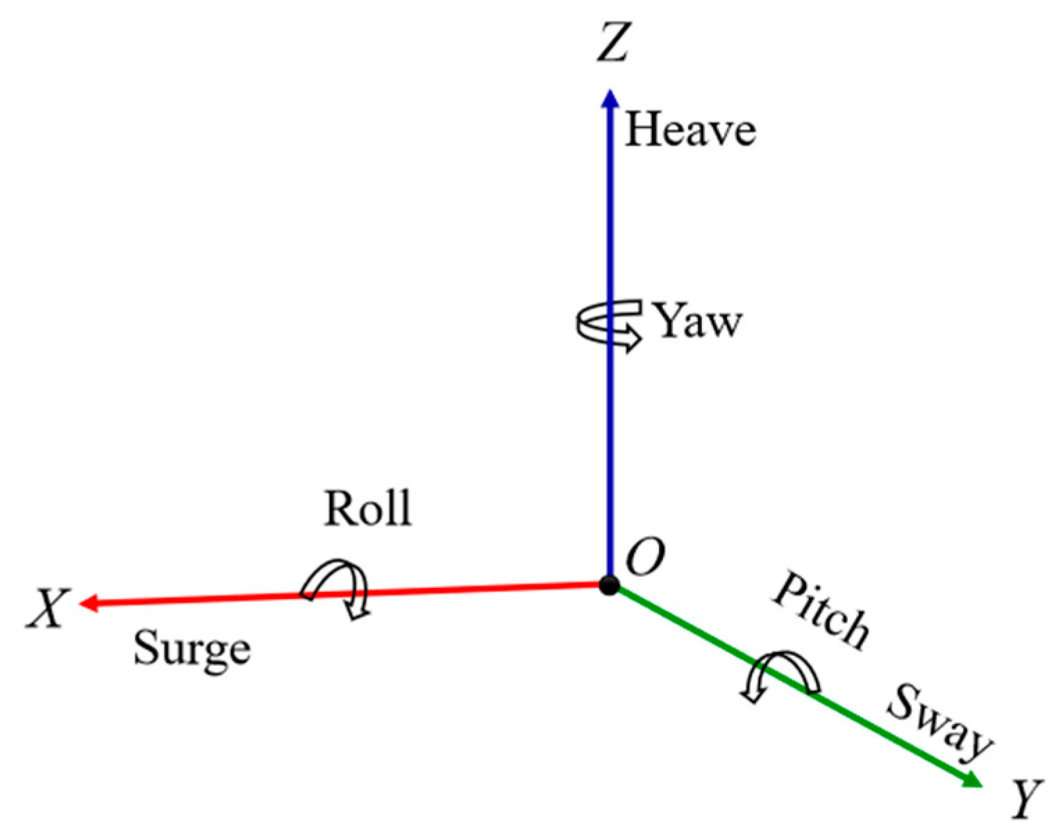
As shown in Figure 1, this paper defines the static coordinate system as O′-XYZ′, the floating system as O-XYZ, and the wave coordinate system as o-xyz with the same z-axis direction. O is the platform’s centre of gravity, and O-XY is the plane parallel to the horizontal plane [41]. Under marine environmental loads, the TLP produces dynamic responses with six DoFs, as shown in Figure 2, including the surge, sway, heave, roll, pitch and yaw.
The mass matrix can be represented as Equation (2).
M = [ m 0 0 0 m z G m y G 0 m 0 m z G 0 m x G 0 0 m m y G m x G 0 0 m z G m y G I x x I x y I x z m z G 0 m x G I y x I y y I y z m y G m x G 0 I z x I z y I z z ]
where M is the mass matrix of TLP [42,43], m is the mass of TLP, Ixx = m·rx2 is the moment of inertia of the pitch, Iyy = m·ry2 is the moment of inertia of the roll, Izz = m·rz2 is the moment of inertia of the yaw, and rx, ry and rz are the radii of rotation of the pitch, roll and yaw, respectively. xG, yG, zG represent centres of gravity. According to Horoub et al. [44], the added mass matrix can be obtained.
The six DoFs of TLP are coupled with each other. For example, the generation of the yaw affects the surge and sway responses. Moreover, the surge and sway responses produce the sinking motion affecting the heave. Then, the coupled degrees of freedom are considered in the stiffness matrix.
K w = [ 0 0 0 0 0 0 0 0 0 0 0 0 0 0 k 33 k 34 k 35 0 0 0 k 43 k 44 k 45 k 46 0 0 k 53 k 54 k 55 k 56 0 0 0 0 0 0 ]
K m = [ k 11 0 0 0 k 15 0 0 k 22 0 k 24 0 0 0 0 k 33 0 0 0 0 k 42 0 k 44 0 0 k 51 0 0 0 k 55 0 0 0 0 0 0 k 66 ]
K = K w + K m
where
K 11 = K 22 = T L z + ρ g A w l δ s L z
K 33 = ρ g A w l + E A L
K 44 = ρ g I w l x cos 3 φ + U z B Q z G n = 1 N T n z T + E I x L cos 2 φ + ρ g A w l ( z B z T ) δ s
K 55 = ρ g I w l y cos 3 β + U z B Q z G n = 1 N T n z T + E I y L cos 2 β + ρ g A w l ( z B z T ) δ s
K 66 = r 2 ( T L z + ρ g A w l δ s L z )
T = n = 1 N T n = U Q
z G T = z G z T
where A is the total cross-sectional area and Awl is the horizontal plane area. Iwlx and Iwly are the moments of inertia of the platform concerning the x- and y-axes, and Ix and Iy are the moments of inertia of the tension leg concerning the x- and y-axes. U denotes the buoyancy, Q denotes the gravity, and Tn denotes the tension of the nth tendon. zB is the buoyancy centre, zG is the gravity centre, and zT is the lower surface coordinates of the platform. L represents the length of the tension leg, and Lz is the vertical height of the top of the tension leg after sinking. θ, β, φ are the angular rotations of the yaw, pitch and roll, respectively. δx and δy represent the displacement in the x and y directions, respectively, and δS is the amount of sinking.
The damping matrix can be expressed as Equation (11) [45].
[ C ] = 2 ξ i [ Φ ] [ λ 1 0 0 0 0 0 0 λ 2 0 0 0 0 0 0 λ 3 0 0 0 0 0 0 λ 4 0 0 0 0 0 0 λ 5 0 0 0 0 0 0 λ 6 ] [ Φ T ] [ M ]
where λi = ωi2, [Φ] is the matrix of the mode shape, ωi is the natural frequency, mi is the modal mass, and ξi = 0.05 (I = 1, 2, 3, …, 6). According to the free decay test, the natural frequencies of the six degrees of freedom are shown in Table 1.

2.2. Wave Load

To calculate the hydrodynamic forces on the TLP, the Morrison equation considering the current velocity is introduced. The horizontal wave force is calculated as follows [45]:
f H = f D + f I = 1 2 C D ρ D ( u + u c ) | u + u c | + C M ρ π D 2 4 d u d t
where fD and fI are the horizontal drag force and inertial force terms, respectively. u is the wave–particle velocity. D presents the cylinders diameters. When the included angle between the ocean current velocity uc and the x-axis is α, its components on the x- and y-axes are expressed by Equations (13) and (14)
{ f D x f D y } = 1 2 C D ρ D u x { 1 + cos α sin α } ( u x + u x cos α ) 2 + ( u x sin α ) 2
{ f I x f I y } = C M ρ π D 2 4 { a x a y }
While the current velocity is zero in the z-axis direction, the wave force can be expressed as follows:
{ f x f y f z } = 1 2 C D ρ D { U x U y U z } + C M ρ π D 2 4 { a x a y a z }
where CD and CM are the drag coefficient and inertia coefficient, respectively. According to API, CD is defined as 0.65, and CM as 2 [47]. Ux, Uy and Uz are the wave–particle velocities, the former two of which include sea current velocity. ax, ay and az are the accelerations. Subscripts x, y and z refer to the components in three directions.

2.3. Wind Load

The NPD wind spectrum is utilized to calculate the wind load [48]:
S N P D ( f ) = 320 ( V 10 10 ) 2 ( z 10 ) 0.45 ( 1 + t 0.468 ) 3.561
t = 172 f ( z 10 ) 2 / 3 ( V 10 10 ) 0.75
where SNPD(f) is the frequency spectrum of fluctuating wind, f is the pulsation frequency, V10 is the hourly mean wind velocity from 10 metres above sea level, and z is the height from sea level. The wind velocity at z at sea level is defined as u(z,t); then, the instantaneous wind velocity at this point can be expressed as follows:
τ ( t ) = V 0 + i = 1 K 2 S N P D ( f i ) f cos ( 2 π f i t + θ i )
where Δf is the equal frequency interval, fi is the linear frequency component, and the random phase angle θi is evenly distributed between 0 and π. Random wind load can be simulated by substituting the NPD wind spectrum formula with the instantaneous wind speed formula.
The average wind speed at height z above sea level is:
u ( z , t ) = V 10 [ 1 + 0.0573 1 + 0.15 V 0 ln ( z 10 ) ] [ 1 0.41 I u ( z ) ln ( t t 0 ) ]
I u ( z ) = 0.06 ( 1 + 0.043 V 0 ) / ( z 10 ) 0.22
Then, the wind force at z can be described as:
F = C F A ( u ( z , t ) x ˙ ) 2
C F = 0.613 m n ( C s C h )
where CF is the wind pressure coefficient, Cs is the shape factor (the cylinder takes the value of 0.5), and Ch is the height coefficient (Ch = 1.00 when h = 0~15.3 m and 1.10 when h = 15.3~30.5 m). A is the projection of wind-affected component on the wind direction. x ˙ is velocity of the structure.

2.4. Current Load

Ocean currents are generally generated by wind drag forces and tidal currents, and the velocity changes with depth. Usually, the surface velocity is the fastest and gradually approaches zero with increasing water depth. According to DNV and relevant references, the current velocity can be expressed as [49]:
V c ( z ) = V ω ( 0 ) ( z d ) + V t ( 0 ) ( z d ) 1 / 7
where d is the water depth, Vc(z) is the current velocity at height z, Vω(0) is the surface velocity of the wind-generated current, and Vt(0) is the surface velocity of tidal seawater.
Then, the ocean current force has the following expression:
F c = 1 2 ρ C D A c V c ( z ) 2
where Ac is the projection area, and Vc is the current velocity. Assuming that the cylinder surface is smooth, CD can be defined as 0.65 according to DNV-RP-C205.

2.5. Mooring Load

The mooring system is coupled with the floating platform through the displacement transfer relationship between the floating platform and the tension leg. Assuming that the tension leg is a nonlinear beam, the dynamic equation is established as:
[ M ] x ¨ + [ K ] x = F e + F z
where Fe is the external force that the Morrison equation can be used to calculate:
f = 1 2 C D ρ D V n | V n | + C M ρ π D 2 4 V ˙ n
V n = e × ( u × e )
where Vn is the current velocity decreasing with increasing water depth, ρ is the fluid density, generally 1.205 kg/m3. e is the unit vector along the axis. Fz is the internal force, which is expressed as:
F i = E A L i 0 ( | L i | L i 0 ) × L i | L i |
| L i | = ( x i x i 1 ) 2 + ( y i y i 1 ) 2 + ( L n ) 2
where n represents the number of elements that the tension leg is divided into, L is the length of the tension leg, and Li0 is the initial length of the tension leg at the ith section.

3. Finite Element Model

3.1. Model Parameters

AQWA is adopted to establish the finite element model of a typical TLP (ISSC TLP) with four columns. This type of floating foundation comprises two parts, a floating platform and mooring, which is suitable for the deep sea with depths ranging from 30 to 1500 m. The parameters of the ISSC TLP considered in this study are given in Table 2.
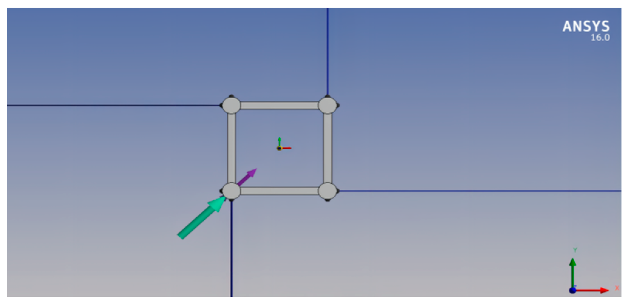
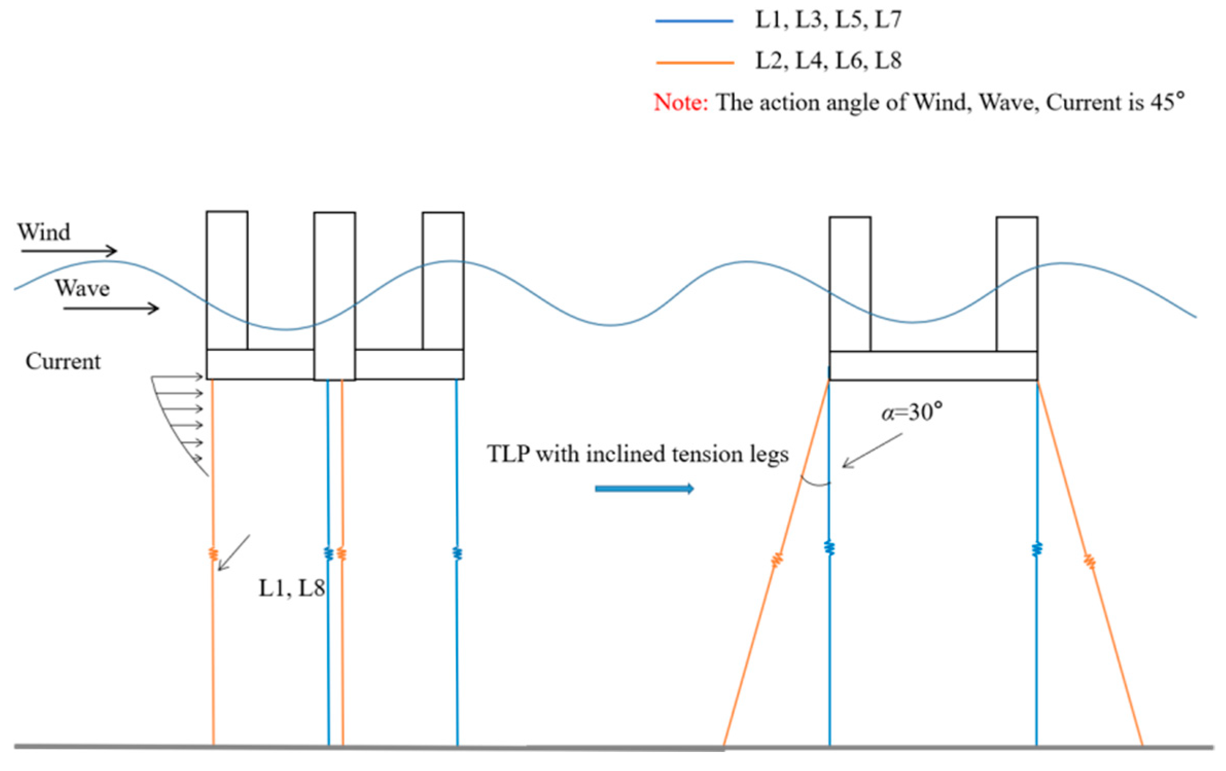
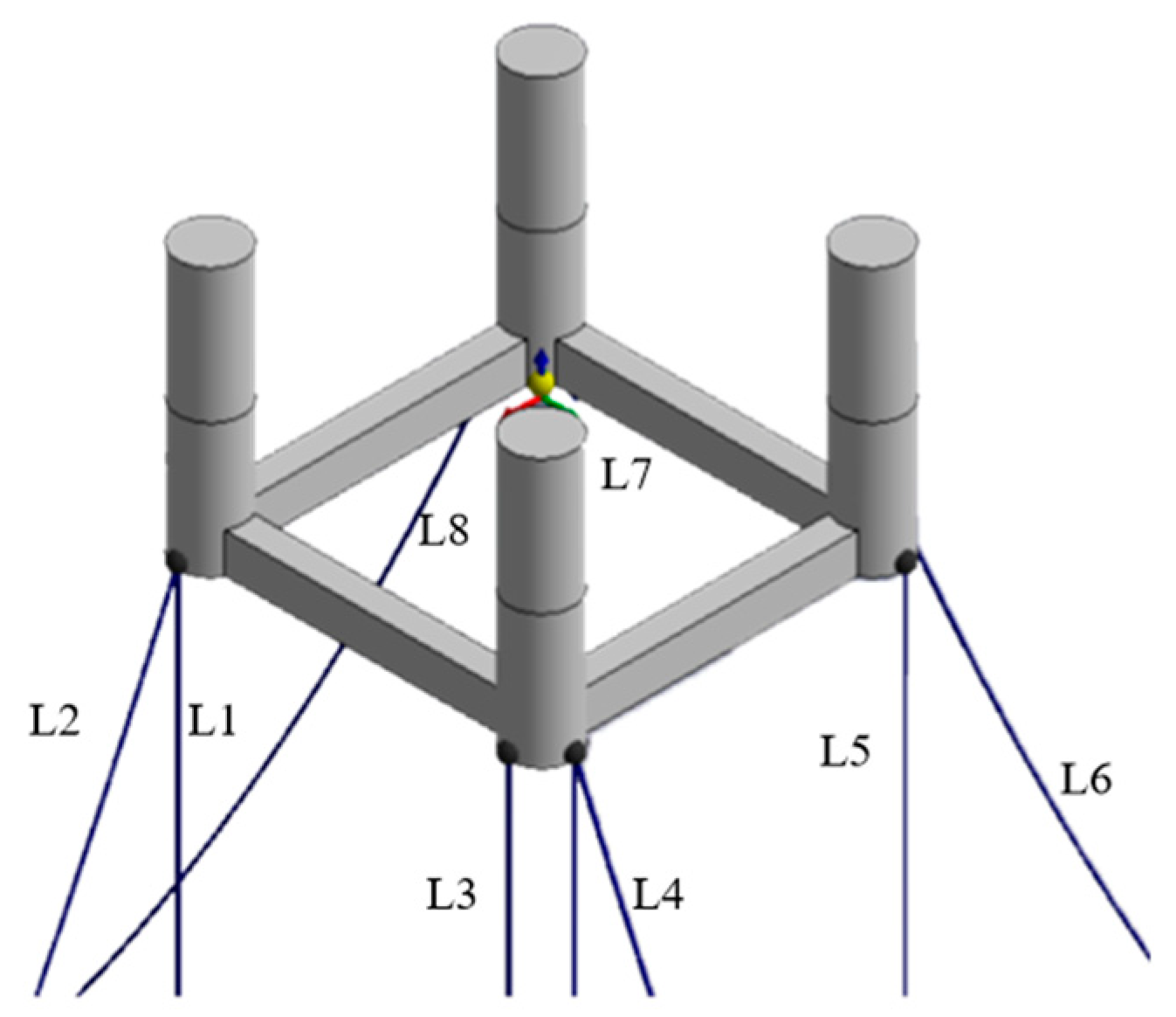
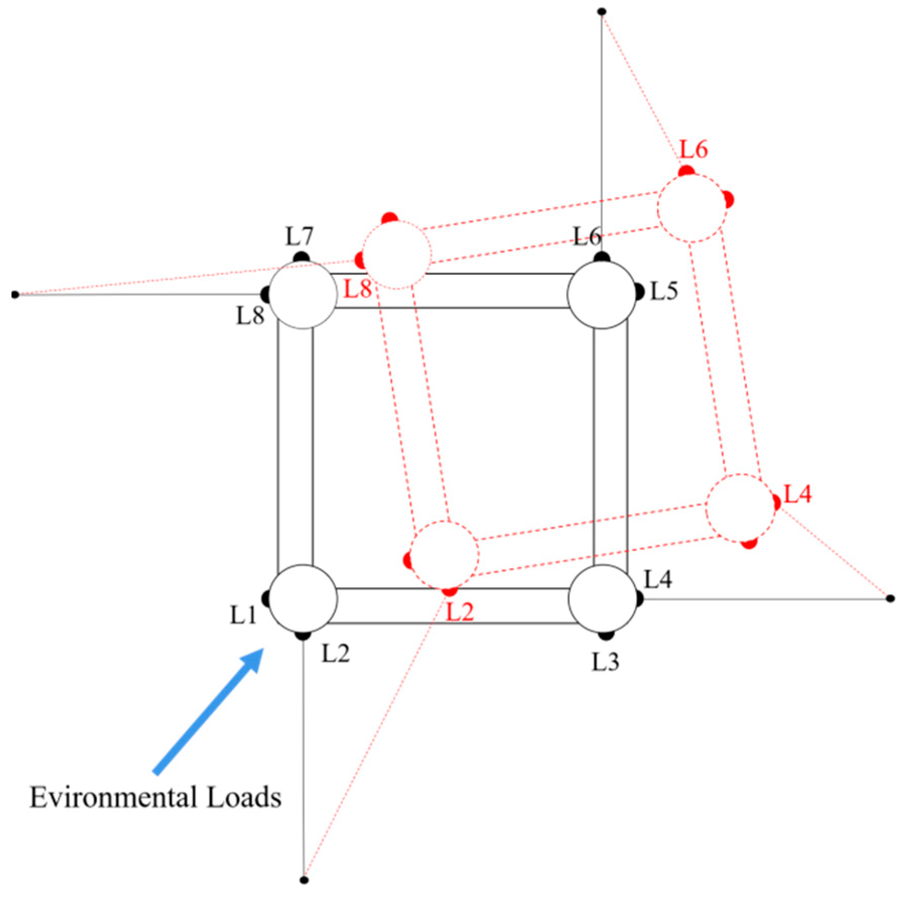
The tension leg of the ISSC TLP is perpendicular to the horizontal plane and connected to the sea floor by an anchoring foundation. Each tension leg contains two tendons. Moreover, tendons with pretension are installed to provide additional vertical stiffness, and two tendons are attached to one column of the TLP. A schematic diagram of the typical ISSC TLP is shown in Figure 3. In this paper, the tension legs of the TLP are numbered from L1 to L8 counterclockwise, starting from the lower-left pillar, where L2, L4, L6 and L8 are tension legs with an inclined angle of 30°. The plan of the model is shown in Figure 4.
The whole domain description of the platform is illustrated in Figure 5, along with meshing details. The surface element model, excluding the tension legs, was meshed, and the mesh size was defined as 2 m, with 20,940 nodes and 21,032 elements. Then, the hydrodynamic response of it was conducted in time domain after set the mooring parameters and its pretension in the menu called “connection”.

3.2. Environmental Conditions

As discussed in the previous, the wind spectrum, and the JONSWAP spectrum is selected to impart the wave load, whose spectral function is given by Equation (32) [49].
S η ( ω ) = α g 2 ω 5 exp [ 5 4 ( ω m ω ) 4 ] γ exp [ ( ω ω m ) 2 2 σ 2 ω m 2 ]
where γ is the spectral peak factor, σ is the peak shape factor, α is the dimensionless wind region function, and ωm is the spectral peak factor.
To better investigate the dynamic characteristics of TLPs in the deep sea, survival conditions are adopted for analysis. Wind and current loads are selected as the survival conditions by their 1-year and 10-year recurrence periods at sea [51]. Firstly, wave loads are immutable, selected by a 10-year recurrence period at sea. Then, different combinations of wind load, wave load and current load are set to judge the sensitivity of the motion response of different degrees of freedom to different loads. The different conditions and their specifications are shown in Table 3.
The incident direction of the three types of loads is 45° with the x-axis, and its schematic diagrams are shown in Figure 6 and Figure 7. Because of the symmetry of the ISSC TLP, the surge, pitch and heave are sufficient to reflect the motion characteristics of TLP.

4. Results and Analysis

4.1. Model Validation

To validate the numerical model, the results of the dynamic equation under a random wave load were compared with those from AQWA. Furthermore, we compared its dynamic responses between survival and special conditions. The wave heights 6.8 m and 8.4 m, and the spectral peak periods 10.2 s and 11.4 s are adopted for simulation. The reliability of the model was verified in two aspects: Figure 8 and Figure 9 display the time-domain analysis, and Figure 10 and Figure 11 reveal the frequency domain analysis.
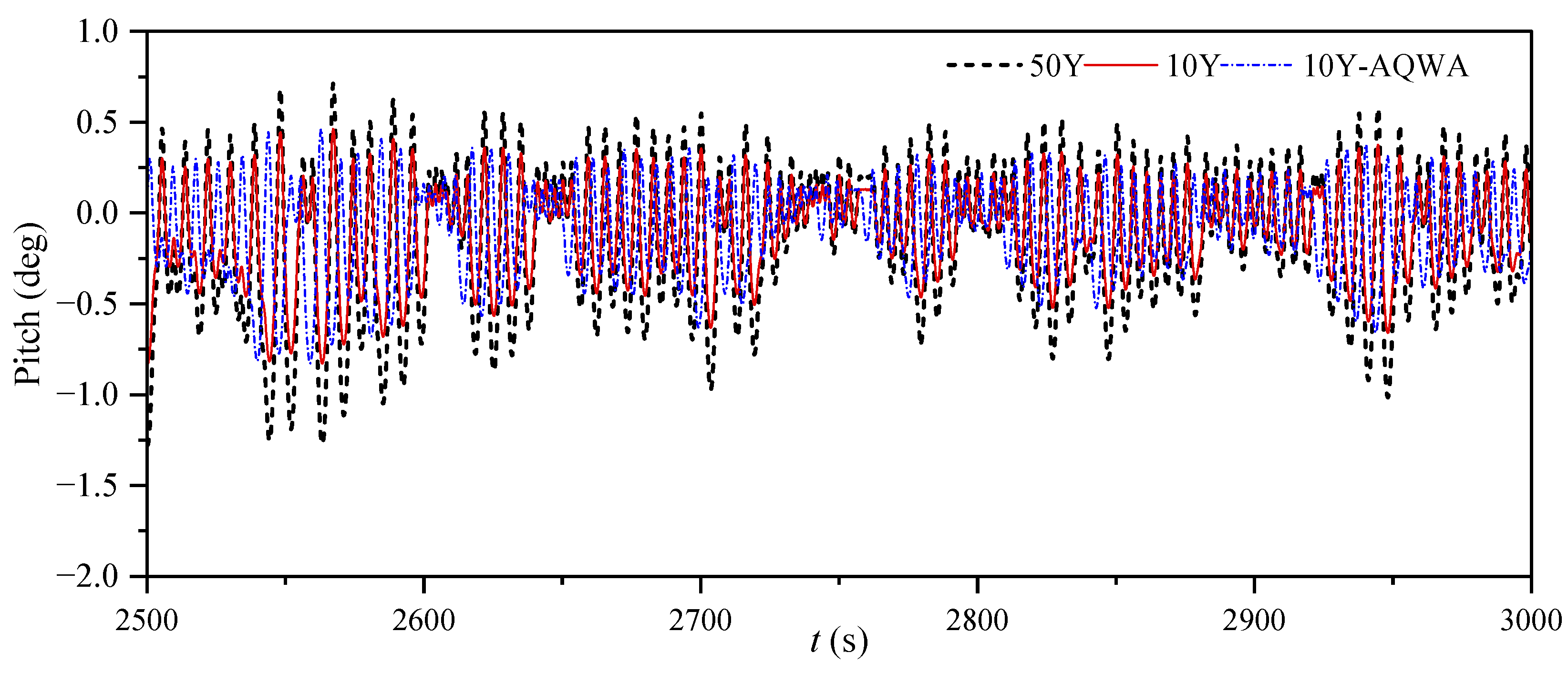
Figure 8 and Figure 9 represent the time series of surge and pitch motion. The surge and pitch are oscillatory motions under the wave load, and their values significantly increase with increasing wave load. The time series obtained by AQWA and numerical simulation share similar changing trend.
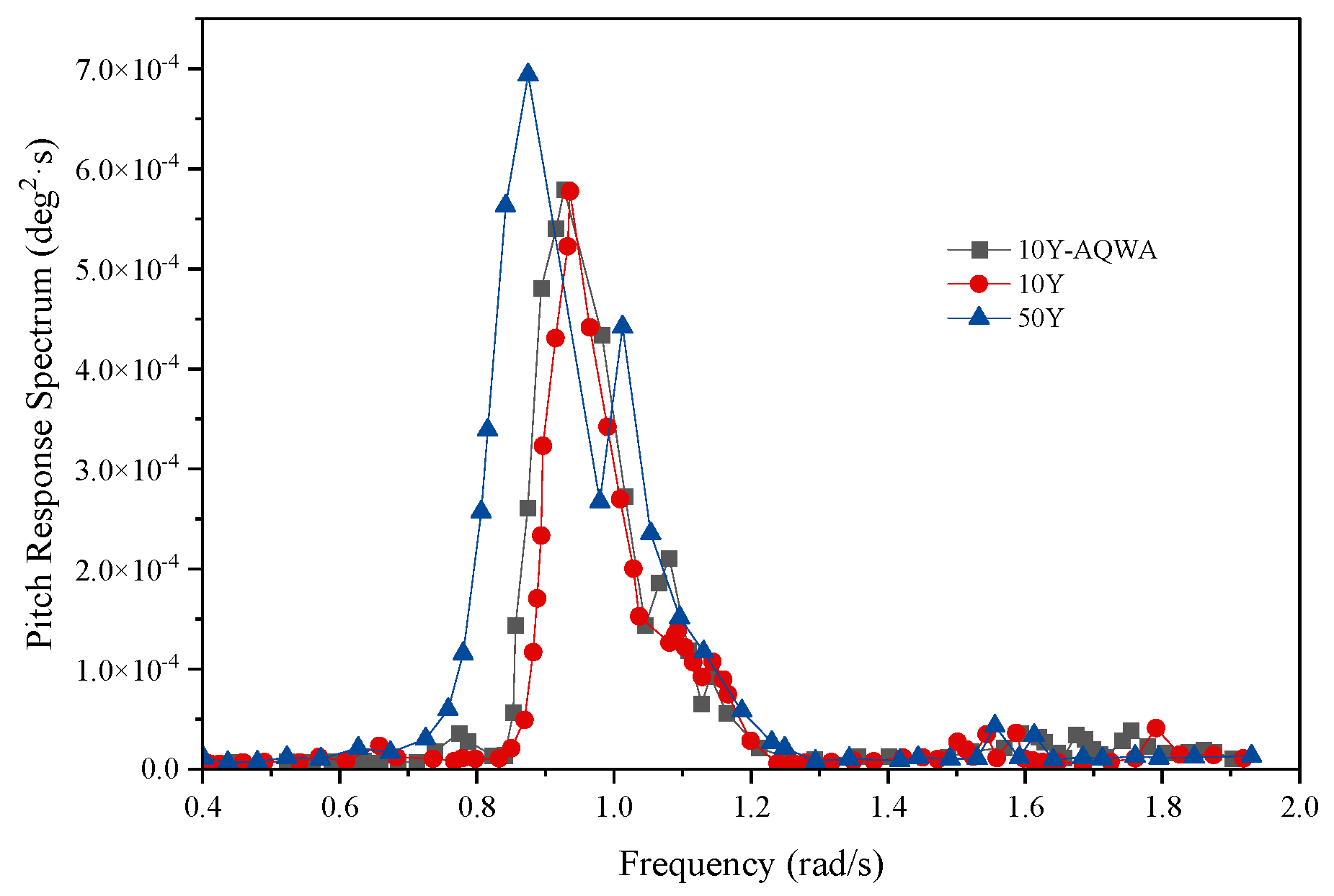
Figure 10 shows that the first spectrum peak of the model’s surge spectrum is near the platform’s natural frequency, and the peak value decreases with increasing sea state. Notably, the second peak value is near the wave spectrum peak frequency and increases with increasing sea state. There is only one prominent spectrum peak in the pitch response spectrum whose frequency approaches the frequency of the wave spectrum peak, as shown in Figure 11. Obviously, the results are consistent with those obtained by previous studies, indicating that the ISSC TLP model established in this study has some certain credibility. To confirm that the inclined tension leg established in this paper has better dynamic characteristics, the time domain calculation results, which can well predict the motion responses of the floating bodies, will be mainly analyzed in the follow-up.

4.2. Response Comparison between Typical TLP and Atypical TLP

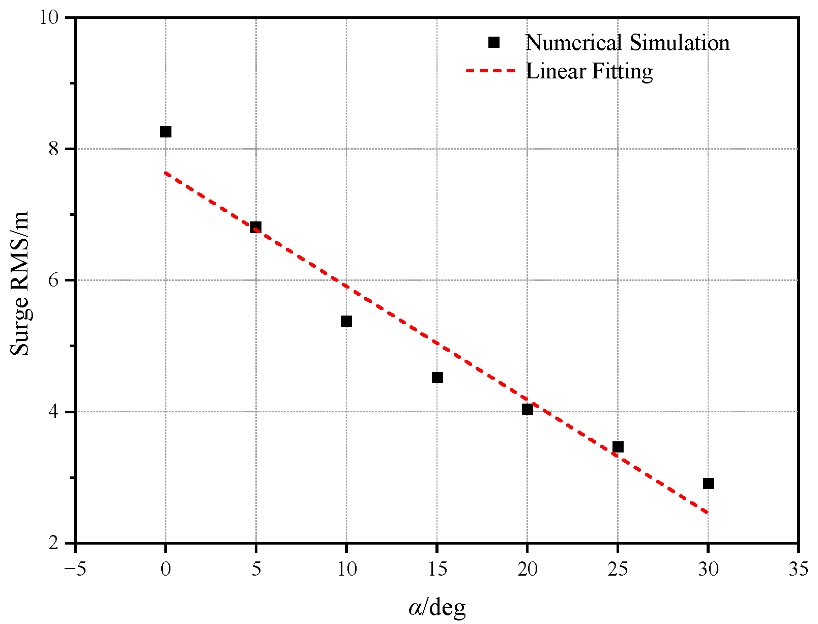
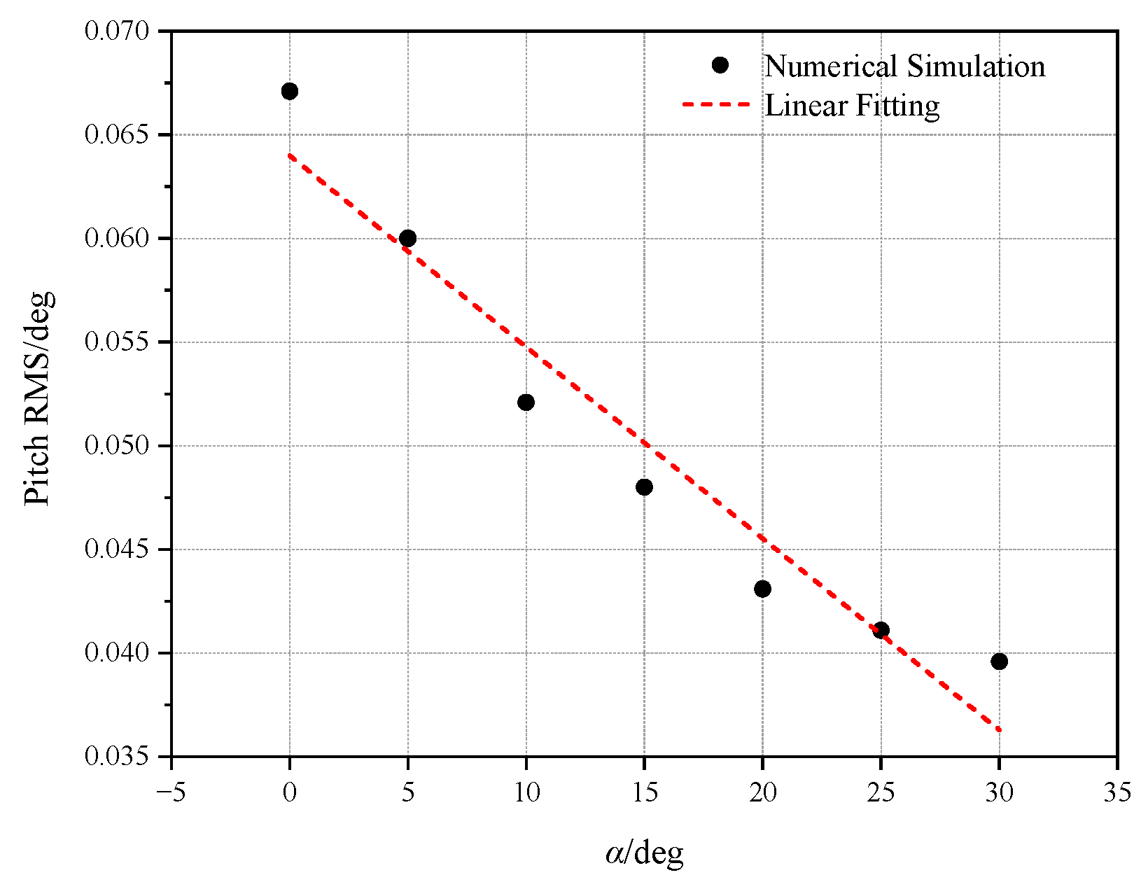
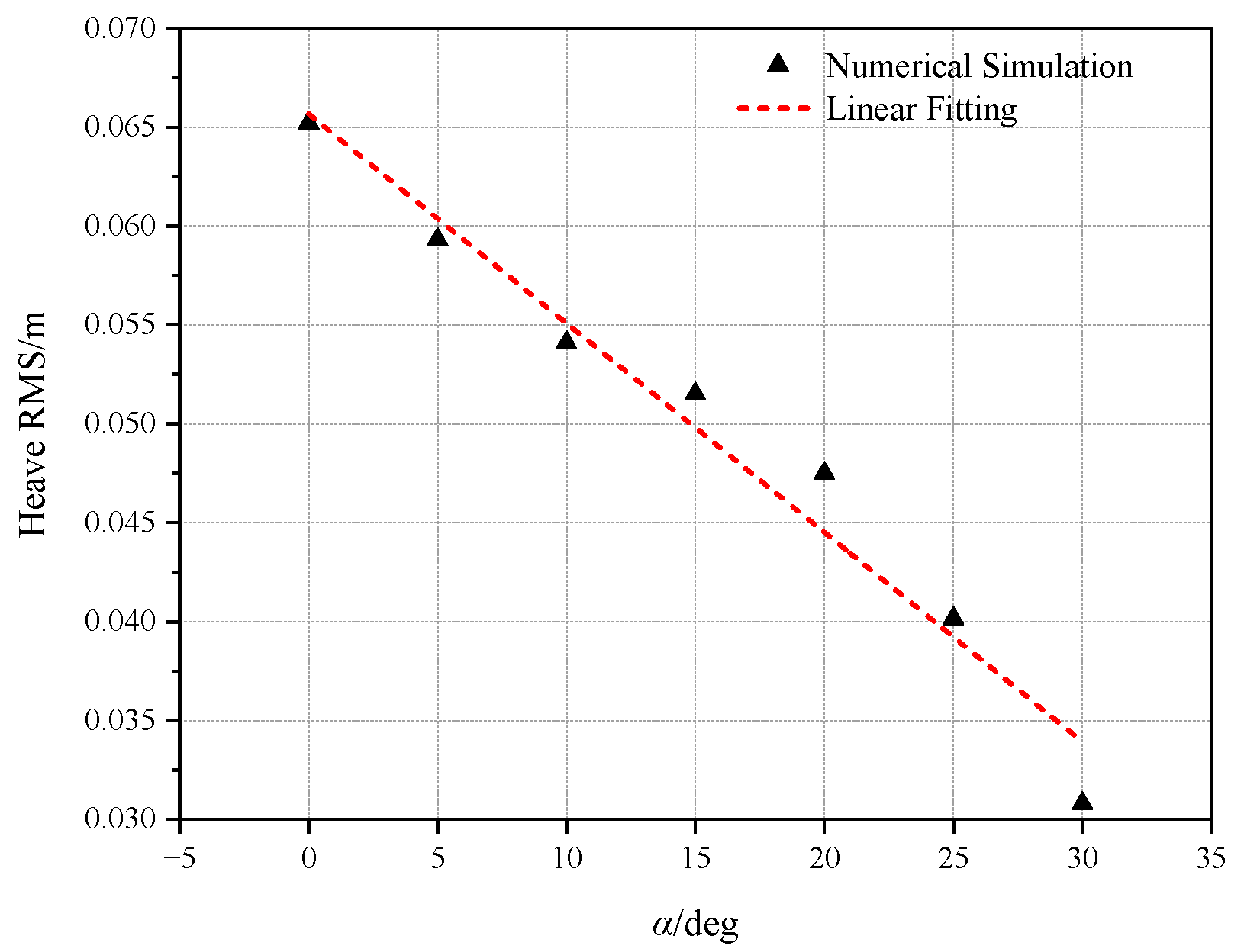
To compare the responses between the ISSC TLP and an atypical TLP possessing inclined tension legs, AQWA was adopted to simulate dynamic responses in the time domain. The inclined angle ranged from 0° to 30°, where 0° corresponded to a typical TLP. The results of the numerical simulation are displayed in Figure 12, Figure 13 and Figure 14, which summarize the root mean square (RMS) of different inclined angles, revealing the fluctuation dispersion degree. It is apparent from Figure 12, Figure 13 and Figure 14 that under the same environmental loads, the inclined tension leg restrains the motions in both the horizontal and vertical directions. The suppression efficiency of the surge and pitch decreases when the inclined angle gradually increases, while that of the heave rises. Therefore, this study set the inclined angle as 30° and analyzed its dynamic characteristics by altering the survival conditions.

4.3. Dynamic Responses of the Atypical TLP under Different Survival Conditions

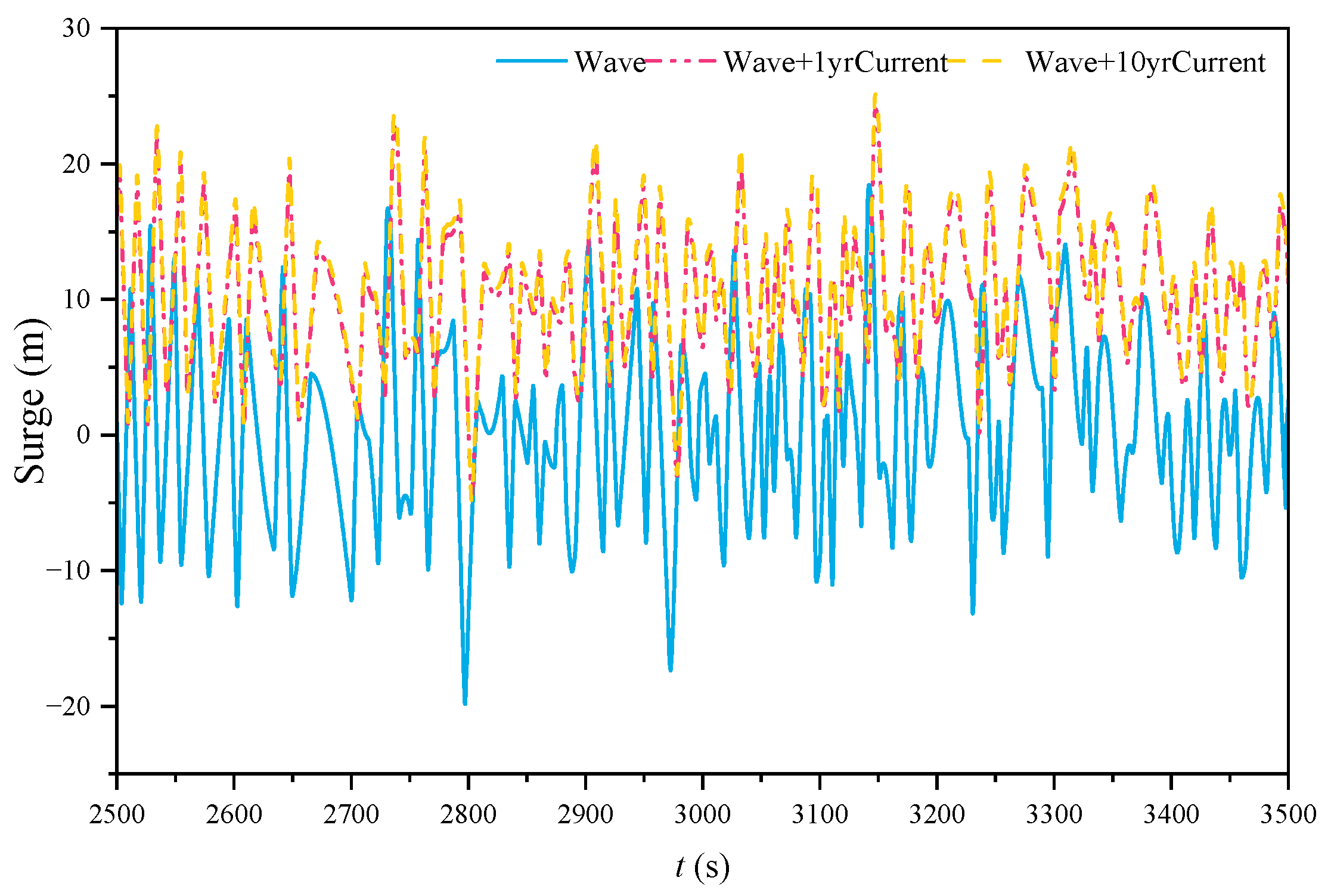
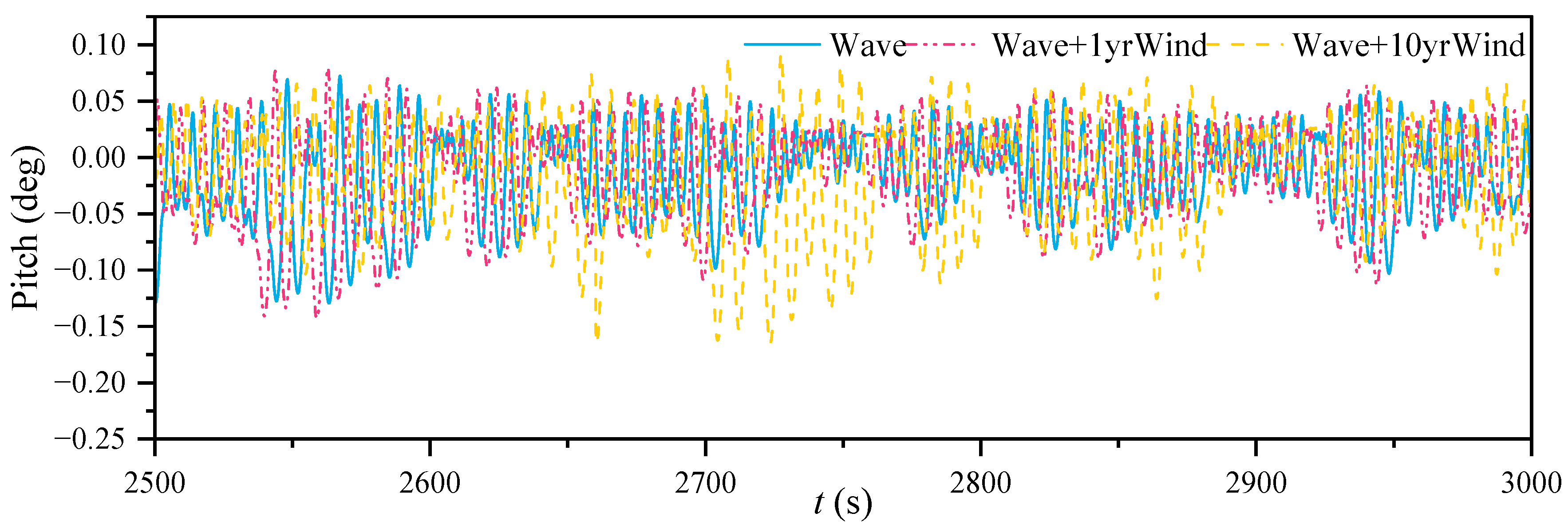
Numerical time-domain simulations are conducted on the variant TLP proposed in this study. The incident marine environmental loads have the same direction. It can be concluded from Figure 15 and Figure 16 that the surge shows oscillatory motion under the action of wave load alone. When wave load accompanied by current load or wind load acts on the structure, the surge displays obvious drift response. However, with increasing wind load, the increase in the surge response is not apparent. With increasing current load, the surge response increases significantly, indicating that the response value of the surge response is more sensitive to the current load. As shown in Figure 17 and Figure 18, there is no significant deviation in the pitch response when the current load is changed, but the amplitude of the pitch response increases significantly with wind load. In previous researches [14,45] it was also found that an impact on the amplitude of pitch under wind and current loads without any drift. As we can see, the impact of the increasing wind load on angular displacement is more obvious than that of the current load. However, based on the current velocity characteristics, the current load has a more significant effect on the linear displacement. So the current load has less influence on pitch than the wind load, which may be attributed to the wind fluctuation. Therefore, the wind-resistant design of structures is extremely significant for floating wind turbines.
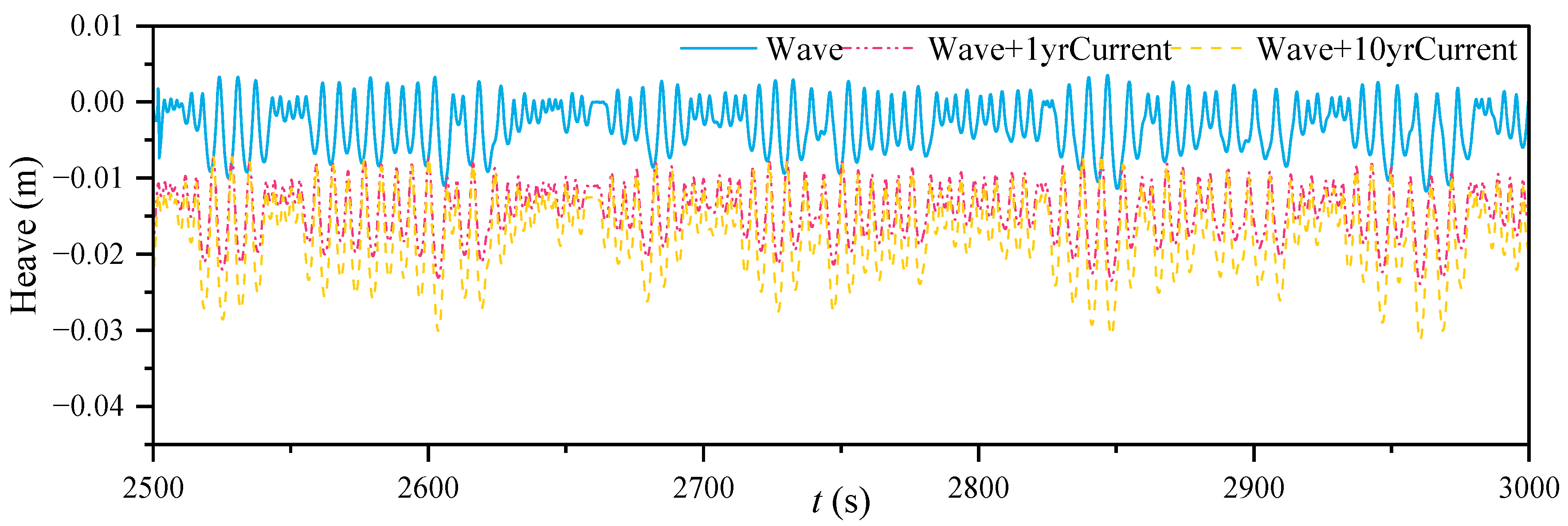
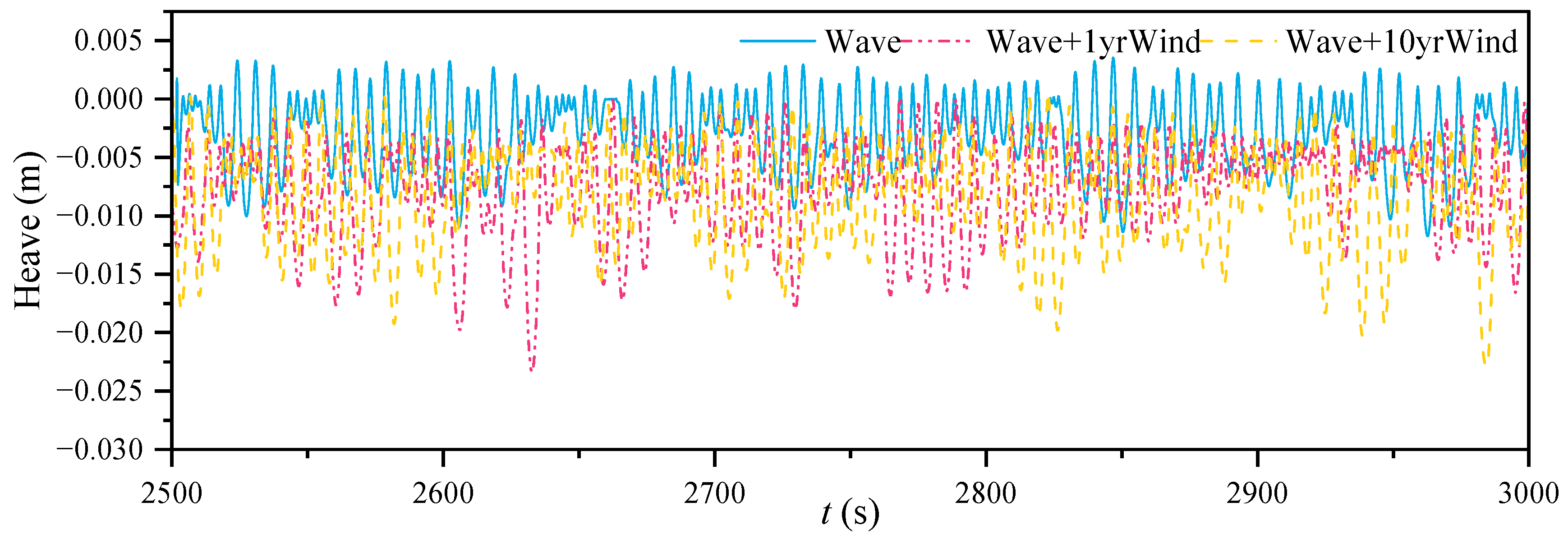
As shown in Figure 19 and Figure 20, the heave mainly presents sinking movement under the action of wind, wave and current loads. When the wave and current loads or wind and wave loads act simultaneously, the heave produces noticeable deviation, and the subsidence under the current load is more significant. It is also observed that the heave value increases with increasing wind or current load.
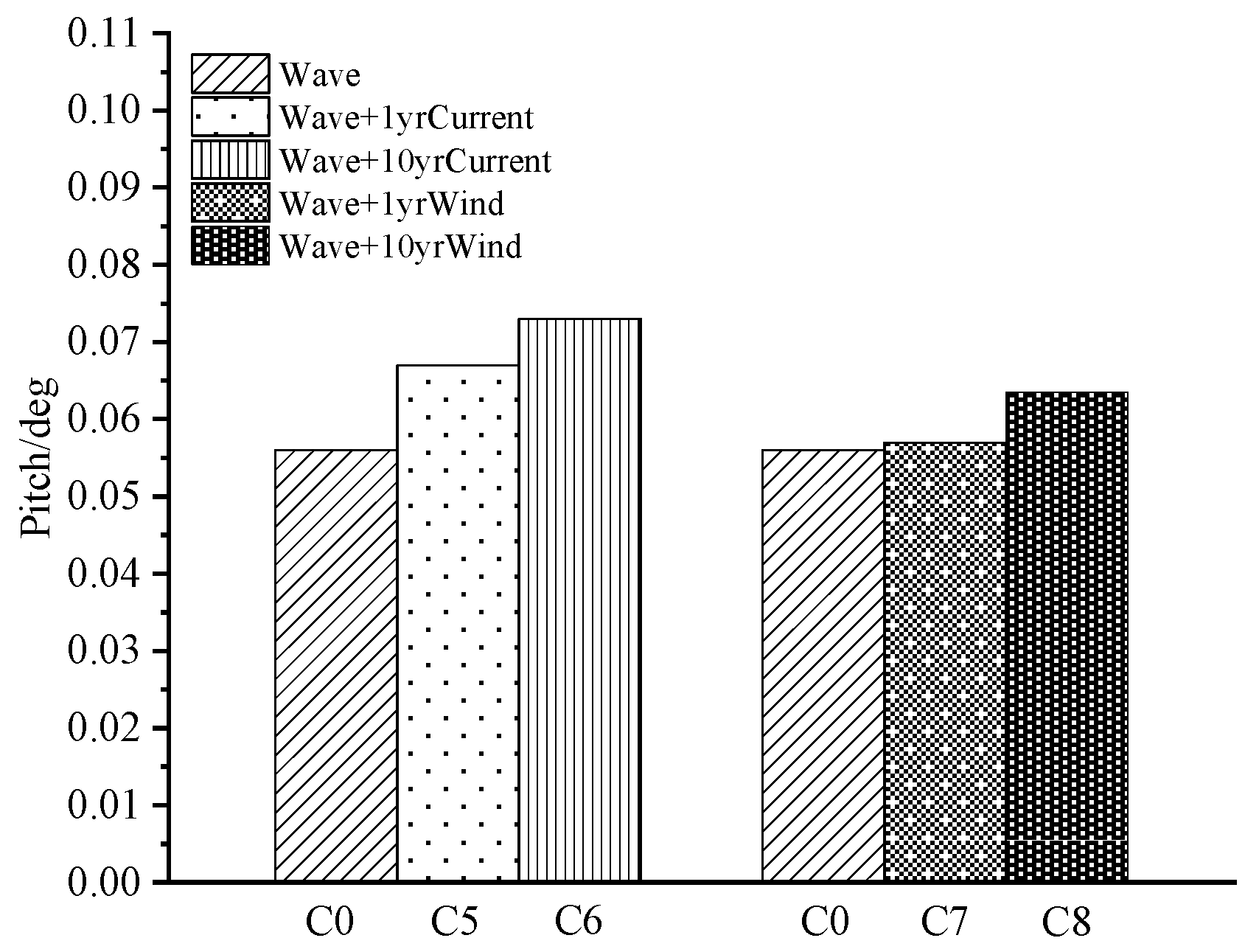
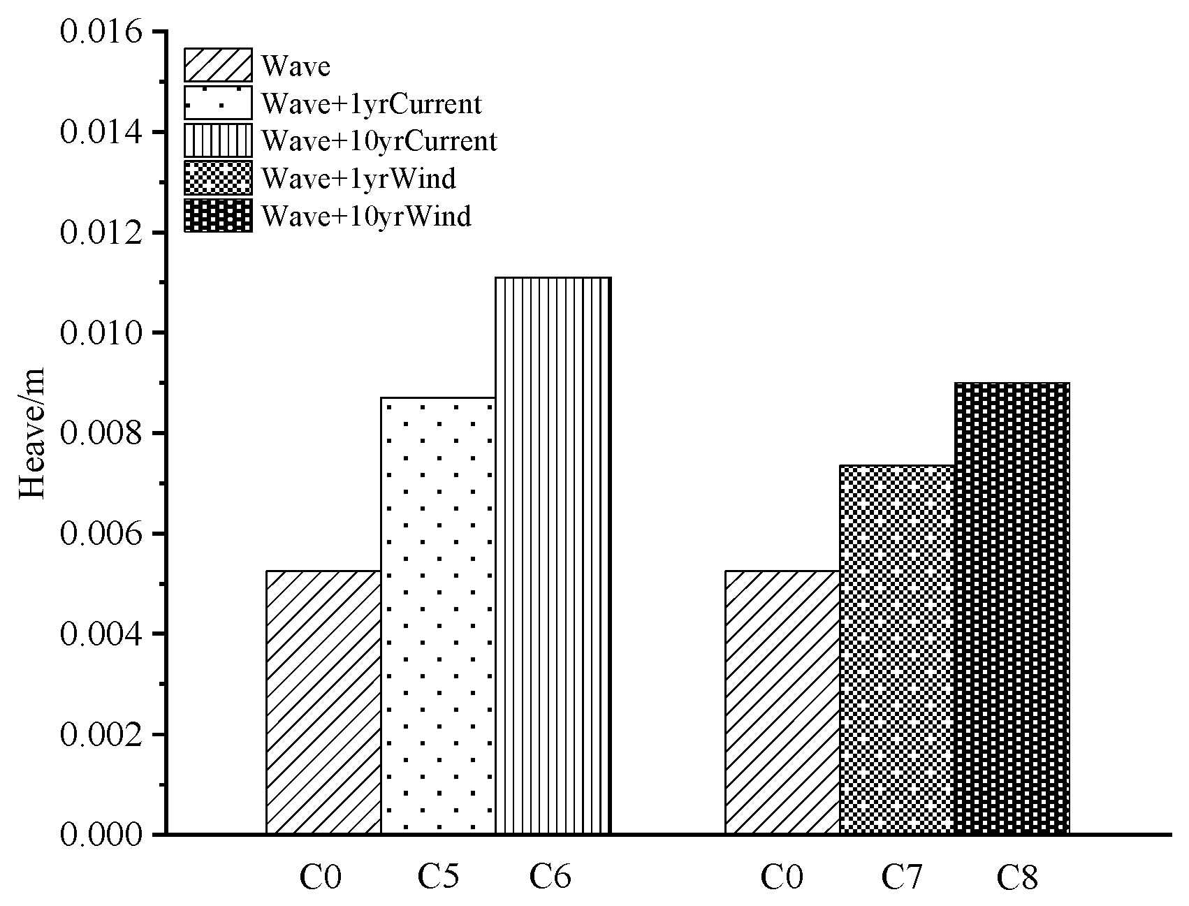
The RMSs for the surge, pitch and heave are shown in Figure 21, Figure 22 and Figure 23. Under the same wave load defined as C0, when the current load and wind load increase, compared with C5, the surge, pitch and heave responses of C6 increase by 29.59%, 8.95% and 27.44%, respectively. Under the same conditions, compared with C7, the surge, pitch, and heave responses of C8 increase by 27.38%, 11.4% and 22.45%, respectively. This indicates that keeping the wave load unchanged, the surge and heave are more sensitive to the current load, while the pitch is more sensitive to the wind load. The heave response produces a large motion response under the wind load. Interestingly, when the wind and current, respectively, increase, the heave response is more sensitive to the current load, presumably caused by the strong coupling of the heave and pitch.

4.4. Variation in Tendon Tension

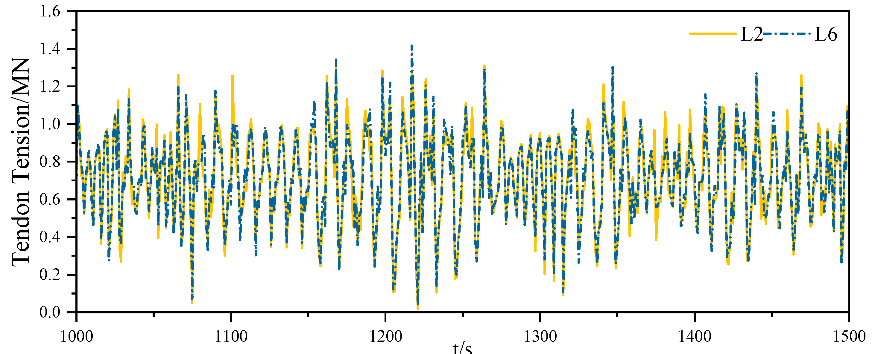
Due to the symmetry of the typical ISSC TLP, when the wind, wave and current act together at 45°, the tension of the tendons is similar in pairs. This section selects the inclined tension legs L2, L4, L6 and L8 as the analysis objects. As seen from Figure 24 and Figure 25, when the angle is 0°, it shows minor variation in the tension range.
Nevertheless, when α = 30°, the tension of the four tendons is different, and their motion under the marine environment load is shown in Figure 26. It can be concluded that the inclined tendons vary more significantly with the platform movement and magnify the original phenomenon of relaxation.
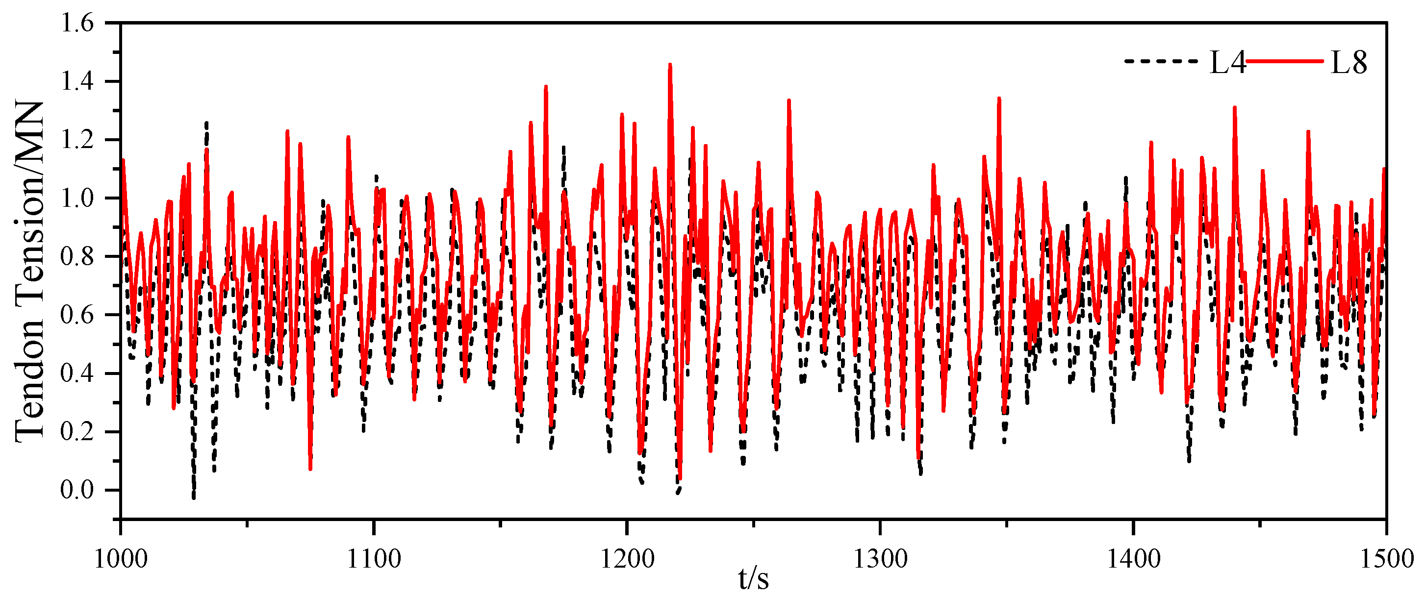
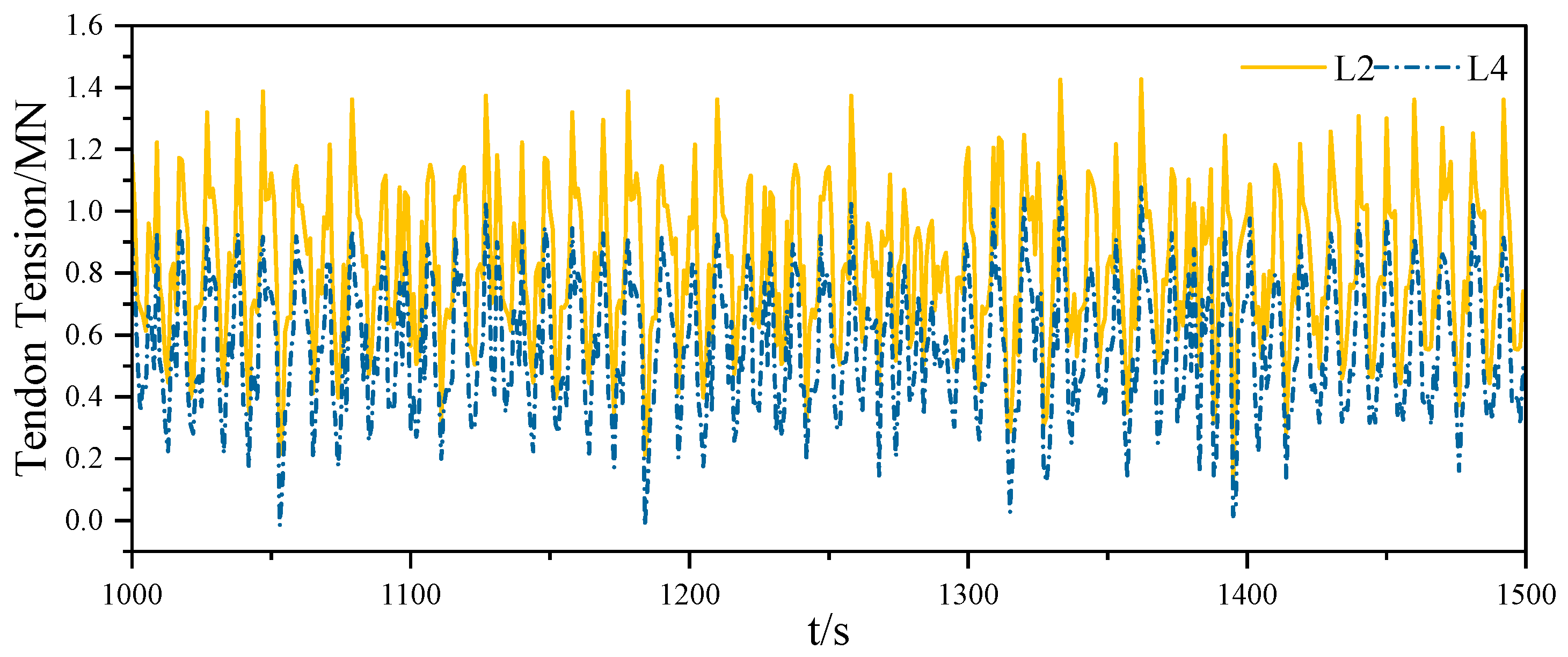
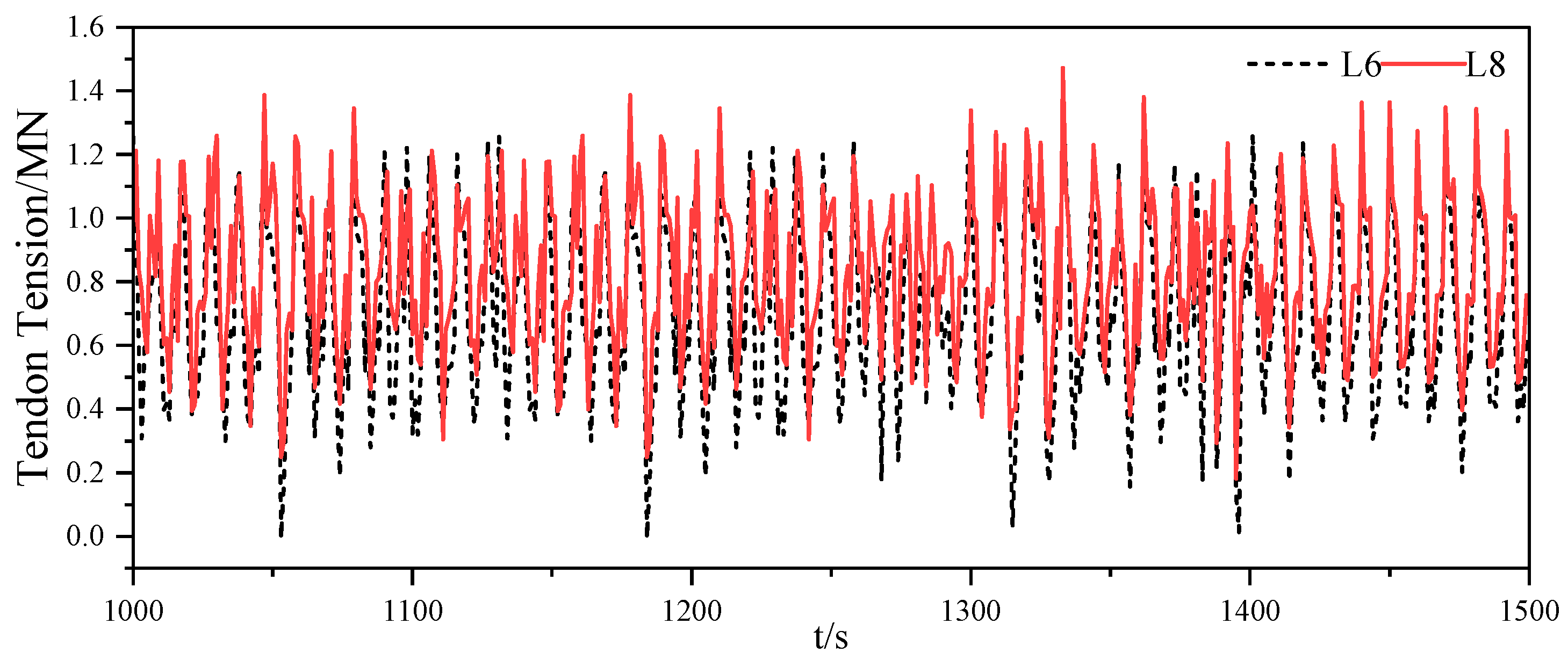
Figure 27 and Figure 28 show that the tension of L2 and L8 is more considerable. Additionally, it should be emphasized that both L4 and L6 show negative values, indicating that the tension leg relaxes to a certain extent in the floating foundation movement. It is predicted that under the same operating conditions, the motion trend of the inclined tendons becomes more complex. Compared with the vertical tension leg, the tendon possessing a certain connection angle is not only more prone to relaxation but also aggrandizes the times of the phenomenon. Thus, the oscillatory motion of atypical TLPs with different degrees of freedom accompanied by the tension and relaxation of the tendon has an essential impact on its service life.

5. Conclusions

To further indicate the improvement of TLP stability, this paper takes a floating system with inclined tension legs as the research object and studies its sensitivity to dynamic responses under different loads. Additionally, the difference and variation in the tension between the inclined and vertical tension legs are investigated. The main conclusions are as follows:
  • The surge and pitch increase significantly with increasing wave load. The first peak of the surge response spectrum is located near the natural frequency of the platform and decreases with increasing sea state, while the second peak is located near the frequency of the wave load spectrum and increases with increasing load. Yet, the pitch response spectral curve has only one distinct spectral peak near the wave spectrum’s peak frequency, and the peak increases in high sea state.
  • The inclined tension legs are confirmed to restrain the surge, pitch and heave motions. Due to the influences of wind and current, drift and sinking happen for the surge and heave motions, respectively. With increasing current load and wind load, the surge response increases by 29.59% and 27.38%, respectively, while pitch increases by 8.95% and 11.4%. This indicates that the surge is more sensitive to the current load, while the pitch is more sensitive to the wind. As the wind load increases, its impact on angular displacement gets more obvious. Meanwhile, based on the fact that current velocity gradually decreases to zero with water depth, the current load has a more significant effect on the linear displacement. It is worth noting that surge and heave motions may be more strongly coupled with each other, which may be the potential reason why the current simultaneously affects the surge and heave more.
  • The tension of vertical tension legs is similar in pairs, while the tension of different inclined tension legs varies greatly. In the process of transverse, longitudinal and rotational shifts of TLP, the tension of forward tendon increases, while the tension of afterward tendon decreases and shows a negative value, indicating that the tension legs are slack to a certain extent in the floating foundation movement. The strained condition of the inclined tension leg is more complicated than that of the typical tension leg, tremendously affecting the fatigue properties of tendons.

Author Contributions

Conceptualization, W.Y.; methodology, N.W.; software, N.W.; validation, N.W. and W.Y.; formal analysis, X.X.; investigation, X.X. and W.Y.; resources, X.X., W.Y. and Z.Z.; data curation, W.Y.; writing—original draft preparation, N.W.; writing—review and editing, Z.Z.; visualization, X.X. and W.Y.; supervision, X.X. and W.Y.; project administration, X.X.; funding acquisition, W.Y. All authors have read and agreed to the published version of the manuscript.

Funding

This work was supported by The Key Program of the National Natural Science Foundation of China (Grant number: 11932010).

Data Availability Statement

The data presented in this study are available on request from the corresponding author. The data are not publicly available due to [the privacy of the data for the follow-up study].

Conflicts of Interest

The authors declare no conflict of interest.

References

  1. Heronemus, W.E. Pollution-Free Energy from Offshore Winds. In Proceedings of the 8th Annual Conference of the Marine Technology Society, Washington, DC, USA, 11–13 September 1972. [Google Scholar]
  2. Marsh, J.R.O. Marine Platforms: US. US 2908141 A[P], 13 October 1959. [Google Scholar]
  3. Huang, Y.; Cheng, P.; Wan, D. Numerical Analysis of a Floating Offshore Wind Turbine by Coupled Aero-Hydrodynamic Simulation. J. Mar. Sci. Appl. 2019, 18, 82–92. [Google Scholar] [CrossRef]
  4. Srinivasan, N. Tension-based tension leg platform: Technologies for ultra deepwater applications. In Proceedings of the ASME 2010 29th International Conference on Ocean, Offshore and Arctic Engineering, OMAE, 20042, Shanghai, China, 6–11 June 2010. [Google Scholar]
  5. Paulling, J.R.; Horton, E.E. Analysis of the Tension Leg Platform. Soc. Pet. Eng. J. 1971, 11, 285–294. [Google Scholar] [CrossRef]
  6. Paulling, J.R. Time domain simulation of semisubmersible platform motion with application to the tension-leg platform. In Proceedings of the SNAME Spring Meeting and STAR Symposium, San Francisco, CA, USA, 25–27 May 1977. [Google Scholar]
  7. Mercier, J.A.; Goldsmith, R.G.; Curtis, L.B. The Hutton TLP: A Preliminary Design. J. Pet. Technol. 1982, 34, 208–216. [Google Scholar] [CrossRef]
  8. Jain, A.K. Nonlinear coupled response of offshore tension leg platforms to regular wave forces. Ocean Eng. 1997, 24, 577–592. [Google Scholar] [CrossRef]
  9. Ketabdari, M.J.; Ardakani, H.A. Nonlinear response analysis of a SeaStar offshore Tension Leg Platform in six degrees of freedom. WIT Trans. Built Environ. 2005, 84, 279–290. [Google Scholar]
  10. Morgan, J.R. Dynamic Analysis of Tension-Leg Platform; Texas A and M University: Collage Station, TX, USA, 1983. [Google Scholar]
  11. Mekha, B.B.; Johnson, C.P.; Roesset, J.M. Effects of different wave free surface approximations on the response of a TLP in deep water. Int. Soc. Offshore Polar. Eng. 1994, 1, 105–115. [Google Scholar]
  12. Han, S.M.; Benaroya, H. Non-linear coupled transverse and axial vibration of a compliant structure, part1: Formulation and free vibration. J. Sound. Vibr. 2000, 237, 875–900. [Google Scholar] [CrossRef] [Green Version]
  13. Kim, C.H.; Kim, M.H.; Liu, Y.H.; Zhao, C. Time Domain Simulation of Non-Linear Response of A Coupled TLP System. Int. J. Offshore Polar. Eng. 1994, 4, 88–96. [Google Scholar]
  14. Gu, J.Y.; Yang, J.M.; Lu, H.N. Studies of TLP Dynamic Response Under Wind, Waves and Current. China Ocean Eng. 2012, 26, 363–378. [Google Scholar] [CrossRef]
  15. Senjanović, I.; Tomić, M.; Hadžić, N. Formulation of consistent nonlinear restoring stiffness for dynamic analysis of tension leg platform and its influence on response. Mar. Struct. 2013, 30, 1–32. [Google Scholar] [CrossRef]
  16. Wang, B.; Tang, Y.G.; Li, Y.; Cai, R.B. Effects of Second-Order Sum-and Difference-Frequency Wave Forces on the Motion Response of a Tension-Leg Platform Considering the Set-down Motion. J. Ocean Univ. China 2018, 17, 311–319. [Google Scholar] [CrossRef]
  17. Chandrasekaran, S.; Jain, A.K.; Gupta, A.; Srivastava, A.; Chandrasekaran, S. Response behaviour of triangular tension leg platforms under impact loading. Ocean Eng. 2006, 34, 45–53. [Google Scholar] [CrossRef]
  18. Lim, D.H.; Kim, Y. Probabilistic analysis of air gap of tension-leg platforms by a nonlinear stochastic approach. Ocean Eng. 2019, 177, 49–59. [Google Scholar] [CrossRef]
  19. Mazarakos, T.P.; Tsaousis, T.D.; Mavrakos, S.A.; Chatjigeorgiou, I.K. Analytical Investigation of Tension Loads Acting on a TLP Floating Wind Turbine. J. Mar. Sci. Eng. 2022, 10, 318. [Google Scholar] [CrossRef]
  20. Jonkman, J.; Larsen, T.; Hansen, A.; Nygaard, T.A.; Gao, Z.; Moan, T.; Fylling, I.J.; Nichols, J.; Kohlmeier, M.; Vergara, J.; et al. Offshore code comparison collarboration within IEA wind task 23: Phase IV results regarding floating wind turbine modeling. In Proceedings of the European Wind Energy Conference (EWEC), Warsaw, Poland, 20–23 April 2010. [Google Scholar]
  21. Jonkman, J.M.; Buhl, M.L., Jr. FAST User’s Guide; National Renewable Energy Laboratory: Golden, CO, USA, 2005.
  22. Canelas, R.; Ferreira, R.; Crespo, A.; Domínguez, J. A generalized SPH-DEM discretization for the modelling of complex multiphasic free surface flows. In Proceedings of the 8th International Spheric Workshop, Trondheim, Norway, 4–6 June 2013. [Google Scholar]
  23. Pan, K.; Ijzermans, R.H.A.; Jones, B.D.; Thyagarajan, A.; van Beest, B.W.H.; Williams, J.R. Application of the SPH method to solitary wave impact on an offshore platform. Comput. Part. Mech. 2015, 3, 155–166. [Google Scholar] [CrossRef] [Green Version]
  24. Sclavounos, P.D.; Lee, S.; DiPietro, J.; Potenza, G.; Caramuscio, P.; De Michele, G. Floating Offshore Wind Turbines: Tension Leg Platform and Taught Leg Buoy Concepts Suppoting 3–5 Mw Wind Turbines. In Proceedings of the European Wind Energy Conference EWEC 2010, Warsaw, Poland, 20–23 April 2010. [Google Scholar]
  25. Pakozdi, C.; Kendon, T.E.; Stansberg, C.T. Breaking wave impact on a platform column: An introductory CFD study. In Proceedings of the ASME 2011 30th International Conference on Ocean, Offshore and Arctic Engineering, Rotterdam, The Netherlands, 19–24 June 2011; Volume 44335, pp. 645–654. [Google Scholar]
  26. Li, L.; Hu, Z.; Wang, J.; Ma, Y. Development and Validation of an Aero-hydro Simulation Code for Offshore Floating Wind Turbine. J. Ocean Wind Energy 2015, 2, 1–11. [Google Scholar]
  27. Mohammad, R.T.; Rahim, S. Perturbation nonlinear response of tension leg platform under regular wave excitation. J. Mar. Sci. Tech. 2018, 23, 132–140. [Google Scholar]
  28. Ghafari, H.; Dardel, M. Parametric study of catenary mooring system on the dynamic response of the semi-submersible platform. Ocean Eng. 2018, 153, 319–332. [Google Scholar] [CrossRef]
  29. Yang, Y. Wind-wave coupling effects on the fatigue damage of tendons for a 10 MW multi-body floating wind turbine. Ocean Eng. 2020, 217, 107909. [Google Scholar] [CrossRef]
  30. Sun, J.; Hu, S.L.J.; Li, H. Laplace domain method for computing the transient response of floating structures to irregular waves. Ocean Eng. 2020, 203, 107200. [Google Scholar] [CrossRef]
  31. Ma, S.; Xu, D.K.; Duan, W.Y.; Chen, J.K.; Liao, K.P.; Wang, H. The numerical study of viscous drag force influence on low-frequency surge motion of a semi-submersible in storm sea states. Ocean Eng. 2020, 213, 107511. [Google Scholar] [CrossRef]
  32. Ren, Y.J.; Vengatesan, V.; Shi, W. Dynamic analysis of a multi-column TLP floating offshore wind turbine with tendon failure scenarios. Ocean Eng. 2022, 245, 110472. [Google Scholar] [CrossRef]
  33. Ma, Z.; Ren, N.; Wang, Y.; Wang, S.; Shi, W.; Zhai, G. A Comprehensive Study on the Serbuoys Offshore Wind Tension Leg Platform Coupling Dynamic Response under Typical Operational Conditions. Energies 2019, 12, 2067. [Google Scholar] [CrossRef] [Green Version]
  34. Rao, D.S.B.; Selvam, R.P.; Srinivasan, N. Hydrodynamic Analysis of Tension Based Tension Leg Platform. OMAE 2012. In Proceedings of the International Conference on Ocean, Offshore and Arctic Engineering, Rio de Janeiro, Brazil, 1 July 2012; pp. 201–207. [Google Scholar]
  35. Adam, F.; Myland, T.; Dahlhaus, F.; Grossmann, J. Scale tests of the GICON®-TLP for Wind Turbines. In Proceedings of the ASME 2014 33rd International Conference on Ocean, Offshore and Arctic Engineering, San Francisco, CA, USA, 8–14 June 2014. [Google Scholar]
  36. Walia, D.; Schünemann, P.; Hartmann, H.; Adam, F.; Gromann, J. Numerical and Physical Modeling of a Tension-Leg Platform for Offshore Wind Turbines. Energies 2021, 14, 3554. [Google Scholar] [CrossRef]
  37. Han, Y.Q.; Le, C.H.; Ding, H.Y.; Cheng, Z.S.; Zhang, P.Y. Stability and dynamic response analysis of a submerged tension leg platform for offshore wind turbines. Ocean Eng. 2017, 129, 68–82. [Google Scholar] [CrossRef]
  38. Ren, N.; Ma, Z.; Shan, B.; Ning, D.; Ou, J. Experimental and numerical study of dynamic responses of a new combined TLP type floating wind turbine and a wave energy converter under operational conditions. Renew. Energy 2020, 151, 966–974. [Google Scholar] [CrossRef]
  39. Wayman, E.N.; Sclavounos, P.D.; Butterfield, S.; Jonkman, J.M.; Musial, W. Coupled dynamic modeling of floating wind turbine systems. In Proceedings of the Offshore Technology Conference, Houston, TX, USA, 1–4 May 2006. [Google Scholar]
  40. Xu, X.; Wei, N.Y.; Yao, W.J. The Stability Analysis of Tension-Leg Platforms under Marine Environmental Loads via Altering the Connection Angle of Tension Legs. Water 2022, 14, 283. [Google Scholar] [CrossRef]
  41. Zeng, X.H.; Li, W.X.; Liu, Y.; Wu, Y.-X. Nonlinear Dynamic Responses of Tension Leg Platform with Slack-Taut Tether. China Ocean Eng. 2009, 23, 37–48. [Google Scholar]
  42. Newman, J. Marine Hydrodynamics; The MIT Press Cambridge: Cambridge, MA, USA, 1977. [Google Scholar]
  43. Uzunoglu, E.; Soares, C.G. A system for the hydrodynamic design of tension leg platforms of floating wind turbines. Ocean Eng. 2019, 171, 78–92. [Google Scholar] [CrossRef]
  44. Mamon, M.H. Dynamic Analysis of a Tension LegPlatforms (TLPs) Inspired by Parallel Robotic Manipulators; IEEE Access: Piscataway, NJ, USA, 2020; pp. 35222–35230. [Google Scholar]
  45. Gu, J.Y.; Yang, J.M.; Lv, H.N. Numerical Simulations and Model Tests of the Mooring Characteristic of A Tension Leg Platform Under Random Waves. China Ocean Eng. 2013, 27, 563–578. [Google Scholar] [CrossRef]
  46. Zhou, B.Z.; Wu, G.X. Resonance of a tension leg platform exited by third-harmonic force in nonlinear regular waves. Philos. Trans. R. Soc. A-Math. Phys. Eng. Sci. 2016, 373. [Google Scholar] [CrossRef] [PubMed] [Green Version]
  47. API RP2A WSD; Designing and Constructing Fixed Offshore Platforms—Working Stress Design. American Petroleum Institute: Washington, DC, USA, 2000.
  48. API RP 2SK; Recommended Practice for Design and Analysis of Stationkeeping for Floating Structures. American Petroleum Institute: Washington, DC, USA, 2005; Volume 10, p. 59.
  49. DNV-RP-C205; Environmental conditions and environmental loads. Det Norske Veritas: Oslo, Norway, 2007.
  50. Taylor, R.E.; Jefferys, E.R. Variability of hydrodynamic load predictions for a tension leg platform. Ocean Eng. 1986, 13, 449–490. [Google Scholar] [CrossRef]
  51. DNV-OS-J101; Design of Offshore Wind Turbine Structures. Det Norske Veritas: Bærum, Norway, 2004.
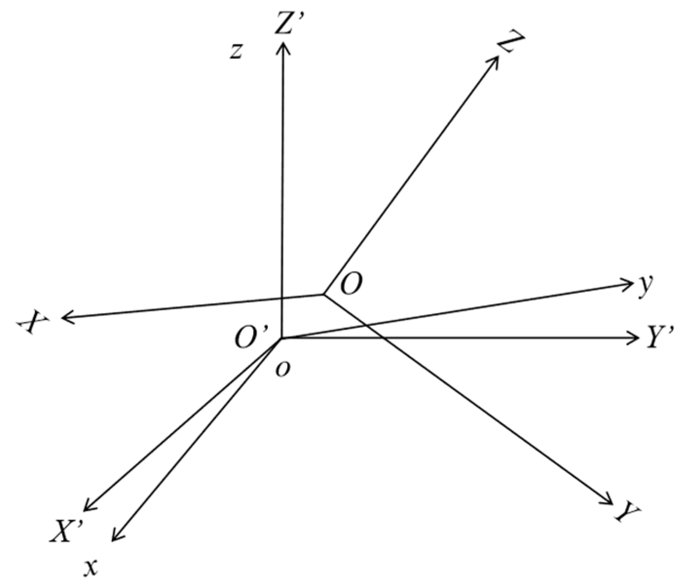
Figure 1. Coordinate system.
Jmse 10 01058 g001
Figure 2. Degrees of freedom.
Jmse 10 01058 g002
Figure 3. Diagram of the ISSC TLP.
Jmse 10 01058 g003
Figure 4. Plan of TLP with inclined tension legs.
Jmse 10 01058 g004
Figure 5. Diagram of grid division.
Jmse 10 01058 g005
Figure 6. Inclined angle of tension legs and the acting direction of the wind, wave, and current.
Jmse 10 01058 g006
Figure 7. 3D view of inclined tension legs. (The tension legs of the TLP are numbered from L1 to L8 counterclockwise, where L2, L4, L6 and L8 are tension legs with an inclined angle of 30°.)
Jmse 10 01058 g007
Figure 8. Surge motion of TLP under different wave heights.
Jmse 10 01058 g008
Figure 9. Pitch motion of TLP under different wave heights.
Jmse 10 01058 g009
Figure 10. Surge response spectrum.
Jmse 10 01058 g010
Figure 11. Pitch response spectrum.
Jmse 10 01058 g011
Figure 12. Surge responses with different inclined angles.
Jmse 10 01058 g012
Figure 13. Pitch responses with different inclined angles.
Jmse 10 01058 g013
Figure 14. Heave responses with different inclined angles.
Jmse 10 01058 g014
Figure 15. Surge response under wave load and current load.
Jmse 10 01058 g015
Figure 16. Surge response under wave load and wind load.
Jmse 10 01058 g016
Figure 17. Pitch response under wave load and current load.
Jmse 10 01058 g017
Figure 18. Pitch response under wave load and wind load.
Jmse 10 01058 g018
Figure 19. Heave response under wave load and current load.
Jmse 10 01058 g019
Figure 20. Heave response under wave load and wind load.
Jmse 10 01058 g020
Figure 21. RMS for surge responses.
Jmse 10 01058 g021
Figure 22. RMS for pitch responses.
Jmse 10 01058 g022
Figure 23. RMS for heave responses.
Jmse 10 01058 g023
Figure 24. Tendon tension of L2 and L6.
Jmse 10 01058 g024
Figure 25. Tendon tension of L4 and L8.
Jmse 10 01058 g025
Figure 26. Diagram of the movement trend of inclined tendons. (L1, L3, L5, L7 are typical tendons, and L2, L4, L6, L8 are inclined tendons with more complicated tension phenomena.)
Jmse 10 01058 g026
Figure 27. Tendon tension of L2 and L4 when the inclined angle is 30°.
Jmse 10 01058 g027
Figure 28. Tendon tension of L4 and L6 when the inclined angle is 30°.
Jmse 10 01058 g028
Table 1. Natural frequencies of the ISSC TLP [46].
SurgeSwayHeaveRollPitchYaw
ωi (rad·s−1)0.06120.06123.4883.4013.4010.0764
Table 2. Main parameters of the ISSC TLP [50].
ParameterValueParameterValue
Column spacing86.25 mTotal pretension14 × 103 kN
Column radius8.44 mInner diameter of tension leg0.3436 m
Column length67.5 mOuter diameter of tension leg0.8 m
Floating box width7.50 mTendon length415.0 m
Floating box height10.50 mKxx1.501 × 109 kN·m−1
Displacement54.5 × 106 kgKzz0.819 × 106 kN·m−1
Total mass40.5 × 106 kgDry weight1575.9 kg·m−1
Ixx82.37 × 109 kg·m2Wet weight240.5 kg·m−1
Iyy82.37 × 109 kg·m2Tendon’s stiffness2.28 × 107 kN
Izz98.07 × 109 kg·m2Area of contour vertical to current5.019 × 103 m2
EA1.335 × 1011 NArea of contour vertical to wind2.194 × 103 m2
Centre of gravity38.0 mWater depth450 m
Draft35.00 m
Table 3. Different combinations of survival conditions.
ConditionsLoadHs (m)Tm (s) γV (m·s−1)Vt(0) (m·s−1)
C1Wind load---5-
C2---11.5
C3Current load----0.8
C4----1.08
C5Wave load + C16.810.2-5-
C6Wave load + C26.810.2-11.5-
C7Wave load + C36.810.2--0.8
C8Wave load + C46.810.2--1.08
Publisher’s Note: MDPI stays neutral with regard to jurisdictional claims in published maps and institutional affiliations.