Article

Design and Reconfiguration of Multicomponent Hydrodynamic Manipulation Devices with Arbitrary Complex Structures

1
State Key Laboratory of Ocean Engineering, Shanghai Jiao Tong University, Shanghai 200240, China
2
Yazhou Bay Institute of Deepsea Technology, Shanghai Jiao Tong University, Sanya 572000, China
3
School of Naval Architecture, Ocean and Energy Power Engineering, Wuhan University of Technology, Wuhan 572000, China
4
No. 92578 Unit of People’s Liberation Army, Beijing 100161, China
*
Author to whom correspondence should be addressed.
J. Mar. Sci. Eng. 2022, 10(7), 861; https://doi.org/10.3390/jmse10070861
Submission received: 18 May 2022 / Revised: 9 June 2022 / Accepted: 13 June 2022 / Published: 24 June 2022
(This article belongs to the Special Issue Hydrodynamics of Offshore Structures)

Abstract

:
Being a powerful strategy to preclude drag and achieve hydrodynamic invisibility, flow field manipulation is attracting widespread attention. In this investigation, we introduce a systematic set of arbitrary-space divide-and-conquer transformation strategies to design complex hydrodynamic cloaks. This theory removes the difficulties associated with the analytic description of complicated and irregular structures to construct hydrodynamic cloaks by adopting the divide-and-conquer algorithm and reconfiguring strategies. It also provides an approach for redistributing the flow field energy and guiding the fluid flow as desired. The proposed theory not only opens up new ideas for improving the speed and concealment of marine vehicles but also provides a new strategy for ensuring the safety of aquatic and underwater structure operations.

1. Introduction

With the increasing depletion of natural resources and the worsening international security situation, the strategic positioning of marine resources is becoming of great importance. A widening range of human activities, such as offshore drilling, underwater oil and gas transportation, and marine vehicle cruising, now take place in deep water. Unfortunately, marine vehicles are inevitably subject to adverse fluid resistance and generate wake, which endangers their stability and safety and even makes their location vulnerable to enemy identification. At the same time, submarine pipelines, as well as offshore oil and gas production platforms, are continuously eroded by water flow, which endangers their safety and reduces their service life. In addition, energy conservation and emission reduction have become common goals worldwide, which has led to an increasing demand for drag reduction and wake elimination technologies for marine vehicles and structures. Therefore, eliminating drag and wake or achieving hydrodynamic invisibility has become important for scientific and engineering applications [1,2].
Recently, numerous strategies have been discovered through which biological systems survive in natural competitive environments. These include (1) reflecting light to precisely match the light behind organisms in order to escape predators [3,4] and (2) cloaking, which exploits unique surface structures to avoid adverse natural conditions [5]. These biological survival phenomena have inspired the scientific community to develop methods in order to flexibly manipulate physical fields. In particular, the advent of transformation optics and artificial metamaterials has given rise to phenomena that have previously been considered impossible [6,7,8,9,10,11]. Being the first theory to enable the manipulation of physical fields, transformation optics endows light with the capability to travel around objects without any reflection or refraction [12,13]. Metamaterials possess many extraordinary properties compared with the materials found in nature. Metamaterials are synthetic composites composed of micro-/nano-structured or microcellular-structured inclusions that can be periodically or randomly organized to achieve the purpose of freely manipulating physical fields. The theory of transformation optics combined with the use of metamaterials has contributed to the implementation of many optical devices with exceptional properties [14,15,16,17,18,19,20,21,22].
The preparation of different functional materials by combining the concepts of transformation optics and metamaterials has attracted considerable attention from researchers in many other disciplines. The most fundamental theory behind these strategic metamaterial designs involves applying multivariable calculus and differential geometry to transform different spatial coordinates. For the thermodynamics field manipulation, heterogeneous and anisotropic thermal conductivities can be obtained utilizing this transformation method, which prompts the heat flux to smoothly bypass the object without any disturbance [23,24,25,26,27]. When the transformation theory is applied to acoustics, an anisotropic density and a scalar bulk modulus are obtained, which result in acoustic cloaking manipulation [28,29,30,31]. In addition, several investigations have been conducted on electromechanical metamaterials [32,33] and elastic solid mechanics [34,35]. Lately, the applications of hydrodynamic field manipulation cloaks have been flourishing, promoting the emergence of further studies in fluid-related fields, and many exciting applications have been developed [36,37,38,39,40,41]. However, the existing theories are only applicable to relatively simple geometric models. Furthermore, the current theoretical framework is only valid for specific cases and cannot be extended to arbitrary body shapes or arbitrary spaces with complex shapes (see the upper part of Figure 1). These limitations narrow the practical application scope of the transformation theory and hinder the application of fluid flow manipulation in more practical situations.
Due to the challenges mentioned above, we propose a novel approach called “arbitrary-space divide-and-conquer transformation theory” to design and reconfigure hydrodynamic cloaks with arbitrarily complex shapes. This theory conquers the hurdles of providing an analytic description of complicated and irregular structures to construct hydrodynamic cloaks by assembling cloaks of different shapes using parametric Bézier curves. This construction method for parametric Bézier curves can flexibly divide any complex geometric model into several segments, and each segment is approximated by parametric curves of different orders, followed by reconfiguration. It also provides an inverse algorithm to construct a Bézier curve through control points and weights, which can facilitate the construction of a Bézier curve arbitrarily or from a known geometric model. The proposed theory provides a strategy to transform arbitrary complex spatial coordinate spaces by twisting coordinate systems, compressing an arbitrarily geometric space into a shell-shaped space to achieve hydrodynamic concealment and excellent drag reduction effect for arbitrary target objects. This investigation enables a powerful form of fluid design, which will allow complex geometries with multicomponents to be undetectable to the external surroundings and remain unaffected by fluid forces.
In addition, the proposed theory retains the form invariance of the Navier–Stokes equations in an arbitrary space, which facilitates the utilization of the existing hydrodynamic theories and practical engineering methods. The theoretical analysis shows that, when applying the theory proposed in this work, the fluid flows around arbitrary target objects without generating resistance, as if no objects were immersed in its flow. In addition, regarding the manufacturing aspects, the piecewise integral approximation method can be used to perform a random flow field manipulation on the required materials with spatially varying properties, and the manufacturing process is not complicated (see the lower part of Figure 1). This work bridges the gap between theoretical investigations and practical applications and enables the fabrication of physical field manipulation devices.
The remainder of this paper is organized as follows: First, the theoretical methods used to establish the arbitrary-space divide-and-conquer transformation theory are introduced in Section 2, including the detailed numerical setups for arbitrary complex geometries and numerical theory validation for model building. In Section 3, the numerical validation and hydrodynamic invisibility are analyzed. Finally, conclusions and limitations are presented in Section 4.

2. Description and Application of the Numerical Theory

It is well known that providing an analytic description of complicated and irregular structures to construct complex hydrodynamic cloaks is extremely difficult. Thus, in this section, we detail the proposed arbitrary-space divide-and-conquer transformation theory, which removes the bothersome constraints imposed by object shapes and spaces in practical engineering and makes the fabrication of physical field manipulation devices more feasible. Figure 2 illustrates the process of the spatial transformation and complex multicomponent geometric construction between different spaces.
It is well known that the Navier-Stokes equations accurately describe a Newtonian fluid flow. In these equations, density ρ and viscosity μ are the two major parameters that define the fluid compressibility and cause drag to the objects in contact with the fluid, respectively. In the natural state, the viscosity coefficient of the fluid is often regarded as constant. However, in order to change the flow direction of the fluid as required, we adopt a theoretical method called transformation hydrodynamics to control the flow of the fluid [42]. The Navier–Stokes equations in the transformed space become
( ρ = V ) t + ( ρ = V V ) = μ = V + ( V ) T p , ρ = t + ( ρ = V ) = 0 ,
where the transformed constitutive density ρ = and viscosity μ = are in the form of inhomogeneous and anisotropic tensors. The relationships between ρ and μ in the original space and ρ = and μ = in the transformed space can then be written as ρ = = C = ρ and μ = = C = μ , respectively, with C = = d e t ( A ) ( A 1 ) T ( A 1 ) , where A represents the Jacobian matrix, which links the original coordinate system with the transformed coordinate system.

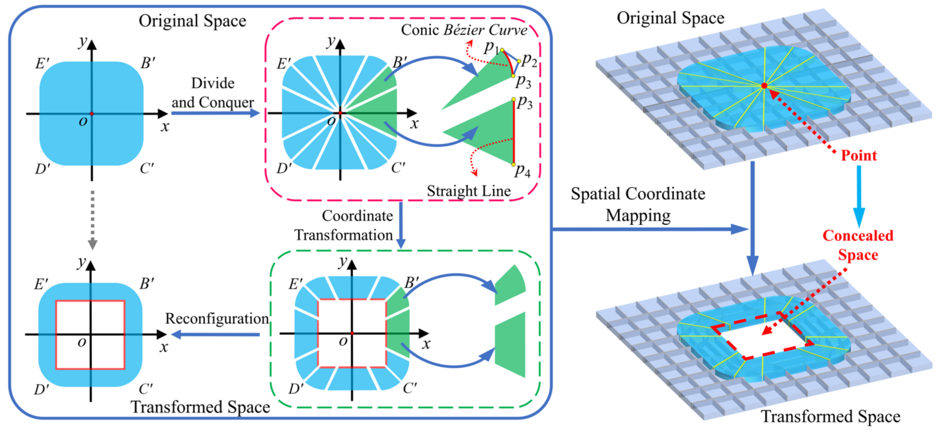
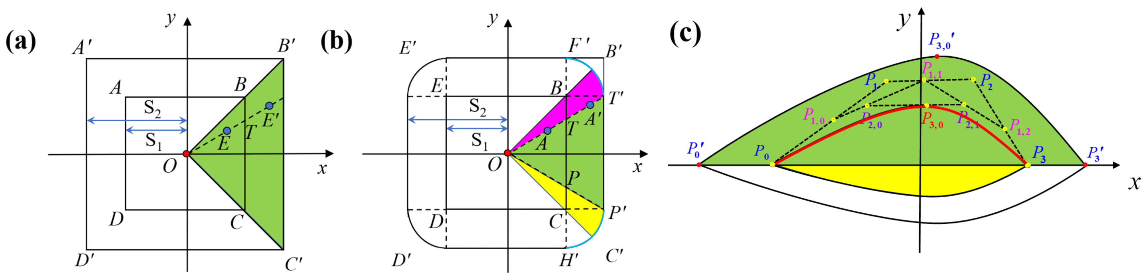
2.1. Divide-and-Conquer Strategy to Construct Arbitrary Geometries

In this section, we introduce a methodology to construct and reconfigure irregular, arbitrarily complex geometries, known as the divide-and-conquer theory. It is often difficult to obtain precise mathematical expressions for many complex geometric curves. Therefore, we propose a method to split a complex curve into multiple segments and then represent each segmented curve with a parametric Bézier curve. Finally, the segmented geometric curves are stitched together and reassembled into the original complex curve [41]. The coordinates of points on the curve are represented separately as an explicit function of an independent parameter, which is written as
C ( u ) = ( x ( u ) , y ( u ) , z ( u ) ) , a u b .
Thus, C ( u ) is a vector-valued function of the independent variable u. The arbitrary interval [a,b] is usually normalized to [0,1]. Using classical mathematics, all the conic curves, including the circle, can be represented using rational functions, which are defined as the ratio of two polynomials as follows:
x ( u ) = X ( u ) W ( u ) , y ( u ) = Y ( u ) W ( u ) , z ( u ) = Z ( u ) W ( u ) , W ( u ) 0 .
where X(u), Y(u), Z(u), and W(u) are polynomials. According to Equation (3), if we select a set of control points {Pi} with weights {wi} in the three-dimensional Euclidean space, the weighted control points are P i w = ( w i x i , w i y i , w i z i , w i ) in the four-dimensional space with wi ≠ 0. Therefore, a weighted nth-degree Bézier curve C w ( u ) is obtained as
C w ( u ) = i = 0 n B i , n ( u ) P i w , B i , n ( u ) = n ! i ! ( n i ) ! u i ( 1 u ) n i , 0 u 1 ,
where the basis functions B i ,   n ( u ) are the classical nth-degree Bernstein polynomials. Then, applying the perspective map to C w ( u ) , an nth-degree corresponding rational Bézier curve is obtained, namely,
C ( u ) = i = 0 n R i , n ( u ) P i , R i , n ( u ) = B i , n ( u ) w i j = 0 n B j , n ( u ) w j , 0 u 1 ,
where R i , n ( u ) are rational basis functions. Using the inverse algorithm to construct a Bézier curve through control points and weights, we can also obtain a Bézier curve arbitrarily or from a known geometric model. Suppose a set of points Q k are given, with k = 0, …, n. If the parameter u ¯ k is assigned to each Q k and an appropriate knot vector U = u 0 , , u m is selected, we can implement the ( n + 1 ) × ( n + 1 ) coefficient matrix system for the linear Equations as follows:
Q k = C ( u ¯ k ) = n i = 0 N i , p ( u ¯ k ) P i ,
u ¯ k = u ¯ ( k 1 ) + Q k Q k 1 d , k = 1 , 2 , , n 1 ,
N i , 0 ( u ¯ k ) = 1 if   u i u < u i + 1 , 0 otherwise ,
N i , p ( u ¯ k ) = u ¯ u ¯ i u ¯ i + p u ¯ i N i , p 1 ( u ¯ k ) + u ¯ i + p + 1 u ¯ u ¯ i + p + 1 u ¯ i + 1 N i + 1 , p 1 ( u ¯ k ) ,
where N i , p ( u ¯ k ) are the pth-degree B-spline basis functions defined on the nonperiodic and nonuniform knot vectors. By solving the linear system of equations obtained from Equation (6), the coordinates of a series of control points p i can be obtained. The number of control points is related to the order of the geometric curve to be constructed; i.e., the order of the constructed curve is the number of control points minus 1. The parametric curve expressions can then be obtained according to these control points.

2.2. Numerical Theory Validation and Model Building

The arbitrary-space divide-and-conquer transformation theory is validated for the construction of multicomponent hydrodynamic manipulating cloaks. This investigation focusses on column objects stretched in the z-axis direction, so the coordinates in the z-axis direction remain unchanged. As can be seen in Figure 3a, the construction of the area enclosed by the A B C D rectangle can be divided into four triangular areas, and the construction process is relatively simple. According to Equation (5), the right boundary of the green triangle area can be expressed as
C ( u ) = ( 1 u ) B + u C ,
which represents a straight-line segment from point B to point C . The four subdomain outer boundaries of the square can be represented conveniently using this method. Then, the four subdomains are spliced through the geometric relationship between the corresponding boundaries, and the geometric expression of the entire geometric region is obtained. When applying the arbitrary-space divide-and-conquer transformation theory, a rectangular area A B C D can be compressed into a conformal shell region between the square-shaped A B C D and ABCD regions, as shown in Figure 3.
Next, we demonstrate the entire process of applying the arbitrary-space divide-and-conquer transformation theory to construct a monolithic hydrodynamic cloak with more complex geometries. As shown in Figure 3b, each corner of the geometry is a quarter arc. Due to the multivalued feature of its outer boundaries, the entire region can be divided into multiple subregions using the divide-and-conquer strategy, and each part is represented by a parametric curve. For the fan-shaped region O F T shown in Figure 3b, the control points are T , B , and F with weights w 0 = w 1 = 1 and w 2 = 2 . Therefore, the arc F T can be expressed using a rational conic Bézier curve as
C ( u ) = ( x ( u ) , y ( u ) ) = 1 u 2 1 + u 2 , 2 u 1 + u 2 , 0 u 1 .
Regarding the divided triangular subdomain O T P (marked in green), the construction process is the same as that in Figure 3a. The geometric expressions of the remaining parts can be obtained similarly.
To create a drag-free space in the flow field in order to protect the object from the disturbance of the external flow field while maintaining the form invariance of the Navier–Stokes equations, we adopt the following transformation to convert the coordinates from the original space to the transformed space: Taking the divided triangular subdomain O T P (marked in green) as an example, we choose an arbitrary point A(x, y) in the original space, whose mapped point in the transformed space is A ( x , y ) ; i.e., O A = r ( x , y ) in the original space, while O A = r ( x , y ) in the transformed space. Therefore, the coordinate transformation equation can be expressed as
r ( x , y ) = r ( x , y ) R 2 ( x , y ) R 1 ( x , y ) R 2 ( x , y ) + R 1 ( x , y ) ,
After applying this coordinate transformation equation, the divided triangular subdomain O T P will be compressed into a trapezoidal domain T P P T , and the triangular domain O T P will become a drag-free space. R 2 ( x , y ) and R 1 ( x , y ) are the outer and inner boundaries of the divided trapezoidal cloak T P P T , respectively. By applying the below transformation invariance (i.e., the unit vectors in the original and transformed spaces must be equal)
r r = x x = y y = z z ,
to Equation (12), the following expressions are obtained:
x = R 2 ( x , y ) R 1 ( x , y ) R 2 ( x , y ) + R 1 ( x , y ) r ( x , y ) x , y = R 2 ( x , y ) R 1 ( x , y ) R 2 ( x , y ) + R 1 ( x , y ) r ( x , y ) y .
To simplify the derivation process, we set
a = R 2 ( x , y ) R 1 ( x , y ) R 2 ( x , y ) , b = R 1 ( x , y ) r ( x , y ) .
Thus, the Jacobian transformation matrix can be obtained as
A =   x x   x y   x z   y x   y y   y z z x z y z z = a + b + xb x xb y 0 yb x a + b + yb y 0 0 0 1 ,
where bx and by represent the derivatives of b with respect to x and y, respectively. Finally, we replace the variables x, y, and z in the original space with the new variables x , y , and z in the transformed space, respectively, for the numerical simulations. According to the relationship between ρ (or μ ) and ρ = (or the transformed viscosity μ = ), the transformed density tensor ρ = can be obtained according to
ρ = = ( x ) 4 + S 1 2 ( y ) 2 ( S 1 x ) ( x ) 3 S 1 y ( x ) 2 0 S 1 y ( x ) 2 1 S 1 x 0 0 0 S 2 S 1 S 2 2 x ( x S 1 ) ρ .
For sector O B T (the pink area in Figure 3b), according to the analytic geometry theory, we can obtain
R 1 = R 1 ( x , y ) = S 1 r / x o r R 1 = R 1 ( x , y ) = S 1 r / x , R 2 = S 1 ( x ( u ) + y ( u ) ) + 2 S 1 x ( u ) y ( u ) + ( d 2 S 1 2 ) r 2 r ,
where d = ( S 2 S 1 ) , and x(u) and y(u) are rational Bézier curve expressions along the x- and y-axes for B T , respectively. For sector O P C , the expressions of R1 and R2 are
R 1 ( x , y ) = S 1 r / x , R 2 = S 1 ( x ( u ) y ( u ) ) + 2 S 1 x ( u ) y ( u ) + ( d 2 S 1 2 ) r 2 r .
As the slope k of point B is equal to that of point B , we can express u in terms of x and y by solving the univariate quadratic equation for u. The relationship between x, y, and u is as follows:
k = y x = y ( u ) x ( u ) = u 2 1 u 2 , 0 u 1 .
The transformation invariance should be referred to again in order to replace the variables x, y, and z in the original space with the new variables x’, y’, and z’ in the transformed space, respectively, for the numerical simulations. Subsequently, the transformed density tensor ρ = and the viscosity tensor μ = can be obtained. The corresponding expressions for the other parts of the square cylindrical fillet cloak can be obtained by applying a rotation matrix to the fan-shaped OB C area on the right-hand side. Taking the upper subdomain as an example, we can apply the rotation matrix to the right green triangular subdomain to obtain the transformed density tensor ρ = and viscosity tensor μ = of the upper subdomain as follows:
x ˜ y ˜ z ˜ = R ( π 2 )   x y z , x ˜ y ˜ z ˜ = R ( π 2 )   x y z ,
R ( θ ) = cos ( θ ) sin ( θ ) 0 sin ( θ ) cos ( θ ) 0 0 0 1 .
The remaining subdomains can be obtained using a similar treatment, and the spatial topological mapping between the original and transformed spaces can be reconfigured. As shown in Figure 3b, the whole drag-free space BCDE’ with round corners will be compressed into the shell region between regions BCDE’ and BCDE.
To further expand the application of the arbitrary-space divide-and-conquer transformation theory, a complex asymmetric cloak design is proposed to improve the universality and generalizability of this theory. In this section, we start with the asymmetric airfoil curve shown in Figure 3c, which is a combination of cubic and conic Bézier curves. From Equations (4) and (5), the expressions for this airfoil curve can be written as
C ( u ) = x u ( u ) = w 0 a 0 ( 1 u ) 3 + 3 w 1 a 1 u ( 1 u ) 2 + 3 w 2 a 2 η 2 ( 1 u ) + w 3 a 3 u 3 w 0 ( 1 u ) 3 + 3 w 1 u ( 1 u ) 2 + 3 w 2 u 2 ( 1 u ) + w 3 u 3 , y u ( u ) = w 0 b 0 ( 1 u ) 3 + 3 w 1 b 1 u ( 1 u ) 2 + 3 w 2 b 2 u 2 ( 1 u ) + w 3 b 3 u 3 w 0 ( 1 u ) 3 + 3 w 1 u ( 1 u ) 2 + 3 w 2 u 2 ( 1 u ) + w 3 u 3 , x l ( u ) = w 0 a 0 ( 1 u ) 2 + 2 w 1 a 1 u ( 1 u ) + w 2 a 2 u 2 w 0 ( 1 u ) 2 + 2 w 1 u ( 1 u ) + w 2 u 2 , y l ( u ) = w 0 b 0 ( 1 u ) 2 + 2 w 1 b 1 u ( 1 u ) + w 2 b 2 u 2 w 0 ( 1 u ) 2 + 2 w 1 u ( 1 u ) + w 2 u 2 ,
where x u ( u ) and y u ( u ) , and x l ( u ) and y l ( u ) represent the coordinates of the upper and lower sections of the airfoil, respectively. In this case, the four control points of the upper airfoil section are p0(0, −0.3L), p1(0.2L, −0.15L), p2(0.2L, 0), and p3(0, 0.3L) with weights w 0 = w 2 = w 3 = 1 and w 1 = 2 , and the three lower control points are p0(0, −0.3L), p1(0.15L, −0.1L), and p2(0, 0.3L) with weights w 0 = 1 and w 1 = w 2 = 2 . L = 0.01 m is the length of the squared computational domain. We can also express u in terms of x and y by solving the univariate quadratic equation for u. In this case, we set
R 1 ( x , y ) = x 2 ( u ) + y 2 ( u ) , R 2 = 2 R 1 ( x , y ) ,
where R1 and R2 are the inner and outer boundaries of the airfoil-shaped cloak, respectively. We select point P 3 , 0 ( x , y , z ) in the original space; its mapped point in the transformed space is P 3 , 0 ( x , y , z ) . The distance between point P 3 , 0 and the origin of the coordinate system is r ( x , y ) = x 2 + y 2 in the original space, and its mapped distance is r ( x , y ) = x 2 + y 2 in the transformed space. According to the arbitrary-space divide-and-conquer transformation theory developed in this study, the upper enclosed area colored in green can be compressed into a conformal shell region P 0 P 3 , 0 P 3 P 3 P 3 , 0 P 0 , as shown in Figure 3c. P 3 , 0 is the level-3 interpolation point. The remaining parts can be treated in the same manner as the upper subdomain. Ultimately, the transformation invariance should be referred to again to replace the variables x, y, and z in the original space with the new variables x , y , and z in the transformed space, respectively, in order to perform the numerical simulations.

3. Results and Discussion

The numerical simulations verify the effects of drag reduction and invisibility obtained by applying the arbitrary-space divide-and-conquer transformation theory to objects inside the cloak. In the following cases, the boundary conditions are no-slip (V = 0) at the surface of the immersed objects and the sidewalls of the domain, and the inflow is applied in the y-axis direction. According to the transformation theory, the transformation tensor C = is in the form of a real symmetric matrix. After diagonalizing this transformation tensor, a matrix with a nonzero principal diagonal is obtained. Following this mathematical operation, the matrix components are reduced from five to three, which greatly simplifies the material properties that need to be considered in actual manufacturing.

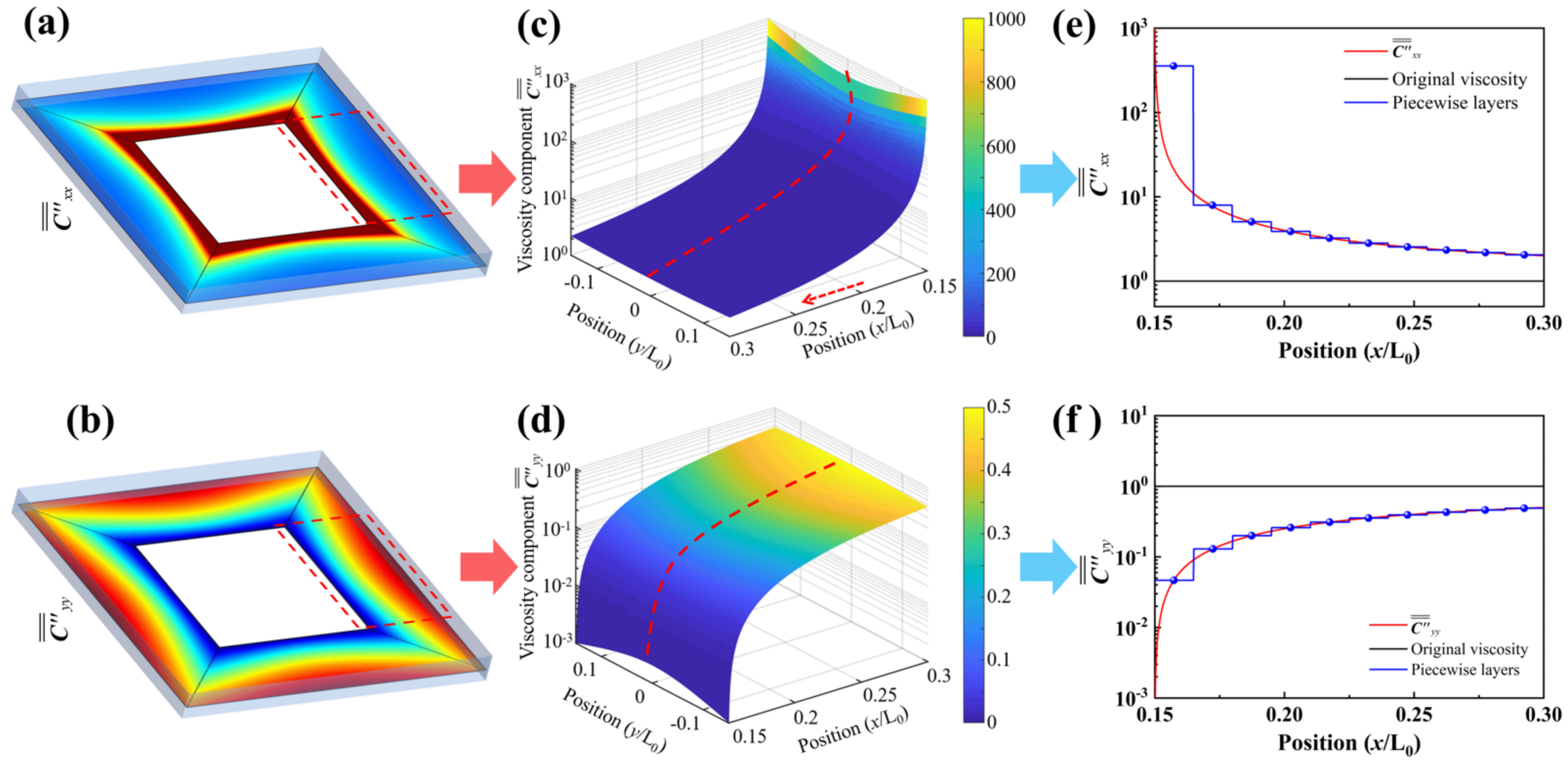
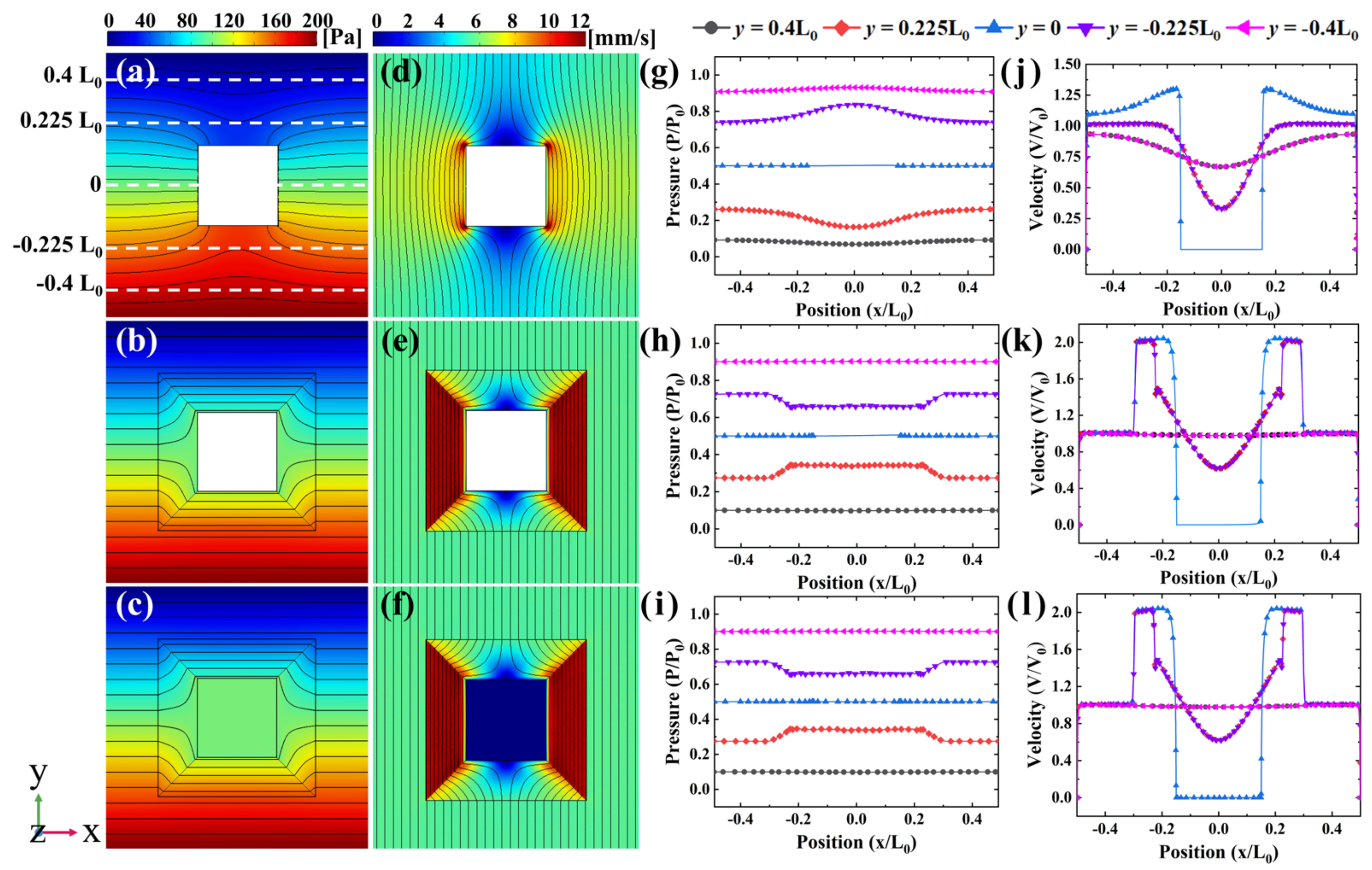
3.1. Analytical Result for the Square Cloak

Figure 4a,b show the spatial distribution of the diagonalized components C = xx and C = yy , respectively, for the transformation tensor C = on the mid-section of the computational domain along the z-axis. Figure 4c,d show the local distribution of the corresponding normalized tensor components for the areas surrounded by the red rectangular dashed lines in Figure 4a,b, respectively. As can be seen from these figures, the transformed tensor components vary continuously in space. Figure 4e,f illustrate the distribution of the transformed tensor components along the red dotted lines in Figure 4c,d, respectively. The black lines in Figure 4e,f represent the original fluid viscosity, while the red lines are the diagonalized transformed tensor components. Although materials whose physical properties vary continuously in space do not exist in nature, such materials can be designed hierarchically using a piecewise integral approximation, as shown by the blue lines in Figure 4e,f. In each layer, this can be achieved using isotropic materials with spatially uniform properties, which still generate a drag-free space while greatly simplifying the actual fabrication process.
Figure 5 depicts the simulated results of a square object immersed in a fluid under different conditions. In the natural state, the presence of the square column would inevitably lead to a disturbance in the entire flow field. As shown in Figure 5a, there is a large pressure difference around the square column, which also affects the flow distribution of the whole flow field. It is also verified that, a viscous resistance and a pressure differential resistance inevitably exist around the body due to the fluid viscosity, and the pressure contour and streamline are distorted in the whole flow field. Moreover, the wake left behind in the flow field indicates the presence of a disturbance, especially in the cases of marine vehicles and underwater structures, which renders these vessels and structures easy to detect.
In order to verify the correctness of this theory under the condition of limited computing resources, and to facilitate comparison with the existing published literature, the flow velocity condition and the size of the calculation domain are made relatively small. When the arbitrary-space divide-and-conquer transformation theory is applied, the square object appears to be covered with a cloak layer. Figure 5b,e show that the pressure and velocity vectors are redirected and return to their original trajectories when outside the cloak, which is in line with previous work [43]. To further verify whether the interior of the square space is indeed a drag-free space, a cloaked-fluid simulation is performed, in which the square object is replaced by fluid. Figure 5c,f show that, in the cloaked-fluid case, the pressure contour and streamline are also highly compressed in the cloak layer, leading to the fluid inside the cloaked region being free from fluid drag. The pressure contour and streamline outside the cloak remain straight as if nothing was immersed in the flow, i.e., to maintain the flow field in a free-flow state.
To quantify the analytical results of the velocity and pressure of the fluid, a set of lines in the flow field is selected (as shown in Figure 5a), along which the velocity and pressure profiles are provided. The pressure is plotted in Figure 5g–i for the selected lines. In Figure 5g, the pressure along the −0.225L0 line gradually increases from 0.73 to 0.83, while the pressure along the 0.225L0 line decreases from 0.27 to 0.17. For the cloaked–object case, the pressure along the −0.225L0 line decreases from 0.73 to 0.65, while the pressure along the 0.225L0 line increases from 0.27 to 0.35, as shown in Figure 5h. The pressure difference around the square object is reduced; thus, the pressure difference resistance is correspondingly decreased. The pressure varies with constant gradients in the left and right subdomains of the cloak layer, as well as in the upper and bottom subdomains, while the pressure is constant along the horizontal direction. The pressure for the cloaked-fluid case (Figure 5i) has the same distribution as that of the cloaked-object case.
Figure 5j shows that the velocity changes irregularly for the cloaked-object case. Regarding Figure 5k–l, the velocity distribution outside the cloak remains a free-flow velocity, and this is the same for the cloaked-object and cloaked-fluid cases. In the vicinity of the left and right outer borders, the velocity increases sharply to twice the free-flow velocity, as shown by the lines at y = ±0.225L0 and y = 0. When approaching the inner borders, the velocity suddenly drops to zero. The distributions of the velocity along the ±0.4L0, ±0.225L0, and 0 lines have the same trends and amplitudes under the corresponding working conditions.

3.2. Analytical Result for the Square Cylindrical Fillet Cloak

In this section, we perform a set of numerical simulations for more complicated cases. Figure 6a,d depict the flow field disturbed by a square-shaped object without a cloak layer. When the arbitrary-space divide-and-conquer transformation theory is applied to the Navier-Stokes equations, the flow field becomes distorted, and a squared drag-free region is opened in the middle, as shown in Figure 6b,c,e,f. Due to this transformation theory, the square-shaped object in the middle of the flow can be easily isolated from its surroundings, and it does not cause any disturbance to the flow when a cloak covers it, which is also invisible to the outside.
Figure 6b,c show that the pressure contours bypass the object smoothly without generating a differential pressure resistance. The streamlines in Figure 6e,f are bent and condensed in the left and right parts of the cloak without impinging on the object and the cloaked fluid. These phenomena demonstrate that the object and fluid in the cloaked region suffer no drag from the surroundings. That is, when the arbitrary-space divide-and-conquer transformation theory is applied, the momentum and energy of the flow are redistributed throughout the flow field to create a drag-free space. Outside the cloak, the free-flow state remains undisturbed, which means that whatever is hidden in the cloaked region will not be perceived by the external environment.
The pressure distribution along five representative lines is plotted in Figure 6g–i. For both the cloaked-object and cloaked–fluid cases, the main difference with respect to the previously discussed square cloak is that the shape of the cloak layer is altered, but the size and performance of the obtained drag-free space are not affected. In addition, compared with the previous square cloak, the pressure changes more smoothly. Figure 6j shows the velocity distribution for the squared–object case, while Figure 6k,l show the velocity distributions for the cloaked cases. When entering the cloak, the velocity increases sharply to twice the free-flow velocity, and it then becomes constant in the horizontal direction, as shown along the line at y = 0. However, inside the rounded-corner subdomains of the cloak, the velocity increases sharply to 1.8 times (rather than twice) the free-flow velocity along the line at y = ±0.225L0. When approaching the inner borders, the velocity drops to zero. Thus far, using the heterogeneous anisotropic material parameters ρ = and μ = , we have been able to realize drag-free spaces and achieve the hydrodynamic cloak effect. In particular, these flow fields can be focused as required or made to avoid objects, returning undisturbed to their original trajectories. The drag that the cloaked object suffers is reduced to less than 10% of that experienced by the uncloaked object.

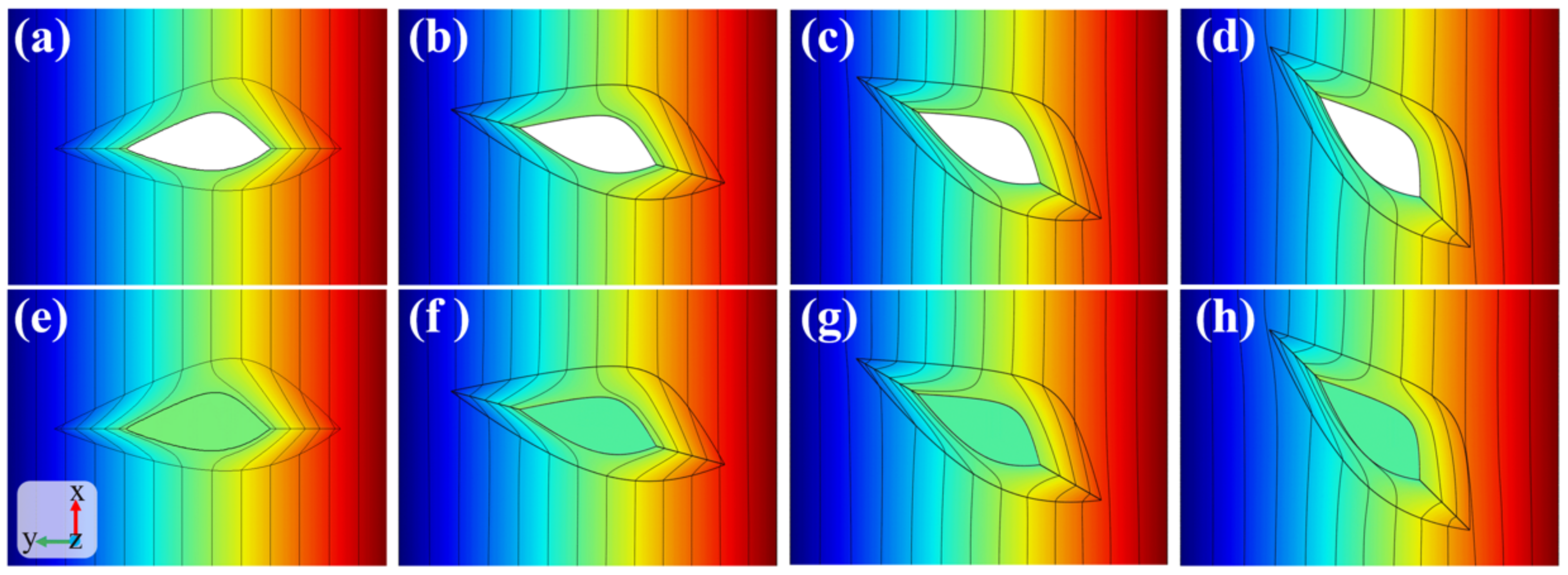
3.3. Analytical Result for the Asymmetric Streamline Body

Finally, in order to validate the universality of the proposed arbitrary-space divide-and-conquer transformation theory, theoretical simulations are carried out on asymmetric streamline bodies. Figure 7a–d present the pressure field flowing around the cloaked airfoil. Figure 7a shows that, when the angle of attack is 0°, the pressure contours in both the upper half and the lower half of the computational domain are vertically distributed. Furthermore, inside the cloak, the pressure contours are deformed and bent smoothly around the airfoil without generating any pressure difference, which indicates that the airfoil is not affected by any differential pressure resistance. However, as the angle of attack increases, the pressure becomes asymmetric. The pressure contours in the upper and lower halves of the computational domain are no longer vertically distributed, which results in the generation of a differential pressure resistance. The cloaked-fluid case, which is shown in Figure 7e–h, also exhibits the same features.
Figure 8 presents the calculated results of the velocity field under different angles of attack. For the cloaked-airfoil case, when the angle of attack is zero, the streamlines outside the cloak remain straight. When the fluid flows into the cloak, the streamlines bypass the airfoil smoothly, as shown in Figure 8a. Figure 8e illustrates that, when the asymmetric airfoil is substituted by fluid, the incoming flow that should penetrate into the cloaked region under natural conditions still has no influence on the cloaked fluid. By contrast, when the angle of attack increases (Figure 8b–d,f–h), the scattering and reflection of the cloak increase, and the resulting no-drag performance of the cloak decreases. The streamlines outside the cloak become deformed, and the degree of curvature increases with the angle of attack. These phenomena are consistent with the flow characteristics of a slender body under different inflow conditions. From the analysis results, it can be inferred that the angle of attack should be kept within an appropriate range when using a slender cloak.
Figure 8i–k display the velocity profiles along different lines, i.e., the purple, yellow, and orange lines that are shown in Figure 8e–h. Figure 8i shows that, when the angle of attack is zero, the velocity outside the cloak remains equal to the free-flow velocity. However, the velocity field outside the cloak does not remain undisturbed at a nonzero angle of attack. This disturbance becomes more pronounced as the angle of attack increases, but it is still negligible compared with the free-flow velocity. However, the scattering and reflection of the wingtip downstream of the flow field become increasingly pronounced.
Figure 8j presents the velocity profiles along the yellow lines. Since the middle part of the airfoil cloak is similar to a bluff-body structure and the boundary curvature undergoes a smooth transition, the change in the angle of attack has a negligible effect on the flow field distribution at that location; thus, the velocity remains the same as the free-flow velocity. When entering the cloaked region, the fluid is static, which indicates the existence of a protected airfoil area in the middle that is not subjected to external forces.
Figure 8j also shows that, in the lower part of the computational domain, the maximum velocity increases with the increase in the angle of attack, while it shows the opposite trend in the upper part. This is clearer in Figure 8k, which shows that the peak in the high-speed zone gradually shifts upward. The distribution characteristics of this flow field can be effectively utilized in practical engineering applications to reduce the potential risks faced by a protected structure by transferring a larger pressure or velocity field to an area where the object can withstand a greater strength or scour. Once again, the feasibility and generality of the arbitrary-space divide-and-conquer transformation theory developed in this study to construct an arbitrarily shaped irregular cloak are verified.

4. Conclusions

In this work, a robust theory called arbitrary-space divide-and-conquer transformation theory was proposed to design and reconfigure arbitrary multicomponent flow field manipulation cloaks. This theory involves transforming one space into an arbitrary space to compress an arbitrary geometric space into a shell space, which enables the realization of hydrodynamic invisibility and excellent drag reduction of arbitrary target objects. By adopting the divide-and-conquer strategy, complex geometries can be divided into multiple simple regions, and each part of the complex geometry can be represented by parametric curves of different orders. The proposed theory overcomes the difficulties of the analytic description of complicated and irregular objects. By combining the arbitrary-space divide-and-conquer strategy and the reconfiguration technology, it is envisaged that new ideas will be developed for the design and manufacture of innovative fluid devices. This will make multicomponent complex objects undetectable and free from external fluid forces. Our findings mark a key step in the design and assembly of arbitrary hydrodynamic complex cloaks, providing an approach suitable for drag reduction, fluid field manipulation, target concealment, and other fields.
Although the theoretical approach proposed in this paper has strong versatility and universality, it also shows many limitations for complex geometric structures that require cloaking and drag elimination. For example, when the geometry is extremely complex, it can only be partitioned into more segments by the segmentation method, and the order of the parameter curves required for each segment will be higher, thus requiring higher computing resources.

Author Contributions

Conceptualization, H.P.; methodology, H.P.; validation, H.P.; formal analysis, H.P.; investigation, H.P.; writing—original draft preparation, H.P.; writing—review and editing, Y.Y., T.L., K.C. and L.S.; funding acquisition, T.L. and K.C. All authors have read and agreed to the published version of the manuscript.

Funding

This research was funded by the Hainan Provincial Natural Science Foundation of China, grant number 520MS071; the National Natural Science Foundation of China, grant number 51979279; and the National Natural Science Foundation of China, grant number 51720105011.

Institutional Review Board Statement

Not applicable.

Informed Consent Statement

Not applicable.

Data Availability Statement

The data presented in this study are available in this article.

Conflicts of Interest

The authors declare no conflict of interest.

References

  1. Alben, S.; Shelley, M.; Zhang, J. Drag reduction through self-similar bending of a flexible body. Nature 2002, 420, 479–481. [Google Scholar] [CrossRef] [PubMed]
  2. Wu, L.; Jiao, Z.; Song, Y.; Liu, C.; Wang, H.; Yan, Y. Experimental investigations on drag-reduction characteristics of bionic surface with water-trapping microstructures of fish scales. Sci. Rep. 2018, 8, 12186. [Google Scholar] [CrossRef]
  3. Stevens, M.; Merilaita, S. Animal camouflage: Current issues and new perspectives. Philos. Trans. R. Soc. B Biol. Sci. 2009, 364, 423–427. [Google Scholar] [CrossRef] [PubMed] [Green Version]
  4. Cronin, T.W. Camouflage: Being invisible in the open ocean. Curr. Biol. 2016, 26, R1179–R1181. [Google Scholar] [CrossRef] [PubMed] [Green Version]
  5. Feng, S.; Zhu, P.; Zheng, H.; Zhan, H.; Chen, C.; Li, J.; Wang, L.; Yao, X.; Liu, Y.; Wang, Z. Three-dimensional capillary ratchet-induced liquid directional steering. Science 2021, 373, 1344–1348. [Google Scholar] [CrossRef] [PubMed]
  6. Pendry, J.B.; Schurig, D.; Smith, D.R. Controlling electromagnetic fields. Science 2006, 312, 1780–1782. [Google Scholar] [CrossRef] [Green Version]
  7. Schurig, D.; Mock, J.J.; Justice, B.J.; Cummer, S.A.; Pendry, J.B.; Starr, A.F.; Smith, D.R. Metamaterial electromagnetic cloak at microwave frequencies. Science 2006, 314, 977–980. [Google Scholar] [CrossRef] [Green Version]
  8. Cai, W.; Chettiar, U.K.; Kildishev, A.V.; Shalaev, V.M. Optical cloaking with metamaterials. Nat. Photonics 2007, 1, 224–227. [Google Scholar] [CrossRef] [Green Version]
  9. Zhang, X.; Liu, Z. Superlenses to overcome the diffraction limit. Nat. Mater. 2008, 7, 435–441. [Google Scholar] [CrossRef]
  10. Cui, T.J.; Smith, D.R.; Liu, R. Metamaterials: Theory, Design, and Applications; Springer: New York, NY, USA, 2010; ISBN 9781441905727. [Google Scholar]
  11. Xu, Y.; Fu, Y.; Chen, H. Planar gradient metamaterials. Nat. Rev. Mater. 2016, 1, 16067. [Google Scholar] [CrossRef]
  12. Leonhardt, U. Optical conformal mapping. Science 2006, 312, 1777–1780. [Google Scholar] [CrossRef] [PubMed]
  13. Xu, L.; Chen, H. Conformal transformation optics. Nat. Photonics 2014, 9, 15–23. [Google Scholar] [CrossRef]
  14. Qian, C.; Chen, H. A perspective on the next generation of invisibility cloaks—Intelligent cloaks. Appl. Phys. Lett. 2021, 118, 180501. [Google Scholar] [CrossRef]
  15. Chen, H.; Chan, C.T.; Sheng, P. Transformation optics and metamaterials. Nat. Mater. 2010, 9, 387–396. [Google Scholar] [CrossRef]
  16. Cai, W.; Shalaev, V.M. Optical Metamaterials; Springer: New York, NY, USA, 2009; ISBN 9781441911506. [Google Scholar]
  17. Chen, H.; Hou, B.; Chen, S.; Ao, X.; Wen, W.; Chan, C.T. Design and experimental realization of a broadband transformation media field rotator at microwave frequencies. Phys. Rev. Lett. 2009, 102, 1–4. [Google Scholar] [CrossRef]
  18. Li, J.; Pendry, J.B. Hiding under the Carpet: A new strategy for cloaking. Phys. Rev. Lett. 2008, 101, 203901. [Google Scholar] [CrossRef] [Green Version]
  19. Huangfu, J.; Xi, S.; Kong, F.; Zhang, J.; Chen, H.; Wang, D.; Wu, B.I.; Ran, L.; Kong, J.A. Application of coordinate transformation in bent waveguides. J. Appl. Phys. 2008, 104, 014502. [Google Scholar] [CrossRef]
  20. Jiang, W.X.; Cui, T.J.; Zhou, X.Y.; Yang, X.M.; Cheng, Q. Arbitrary bending of electromagnetic waves using realizable inhomogeneous and anisotropic materials. Phys. Rev. E Stat. Nonlinear Soft Matter Phys. 2008, 78, 066607. [Google Scholar] [CrossRef]
  21. Luo, Y.; Chen, H.; Zhang, J.; Ran, L.; Kong, J.A. Design and analytical full-wave validation of the invisibility cloaks, concentrators, and field rotators created with a general class of transformations. Phys. Rev. B Condens. Matter Mater. Phys. 2008, 77, 125127. [Google Scholar] [CrossRef] [Green Version]
  22. Yan, M.; Ruan, Z.; Qiu, M. Cylindrical invisibility cloak with simplified material parameters is inherently visible. Phys. Rev. Lett. 2007, 99, 233901. [Google Scholar] [CrossRef] [Green Version]
  23. Fan, C.Z.; Gao, Y.; Huang, J.P. Shaped graded materials with an apparent negative thermal conductivity. Appl. Phys. Lett. 2008, 92, 251907. [Google Scholar] [CrossRef]
  24. Narayana, S.; Sato, Y. Heat flux manipulation with engineered thermal materials. Phys. Rev. Lett. 2012, 108, 214303. [Google Scholar] [CrossRef]
  25. Schittny, R.; Kadic, M.; Guenneau, S.; Wegener, M. Experiments on transformation thermodynamics: Molding the flow of heat. Phys. Rev. Lett. 2013, 110, 195901. [Google Scholar] [CrossRef] [Green Version]
  26. Dai, G.; Shang, J.; Huang, J. Theory of transformation thermal convection for creeping flow in porous media: Cloaking, concentrating, and camouflage. Phys. Rev. E 2018, 97, 022129. [Google Scholar] [CrossRef] [PubMed] [Green Version]
  27. Yeung, W.S.; Mai, V.P.; Yang, R.J. Cloaking: Controlling thermal and hydrodynamic fields simultaneously. Phys. Rev. Appl. 2020, 13, 064030. [Google Scholar] [CrossRef]
  28. Cummer, S.A.; Schurig, D. One path to acoustic cloaking. New J. Phys. 2007, 9, 45. [Google Scholar] [CrossRef]
  29. Cummer, S.A.; Popa, B.I.; Schurig, D.; Smith, D.R.; Pendry, J.; Rahm, M.; Starr, A. Scattering theory derivation of a 3D acoustic cloaking shell. Phys. Rev. Lett. 2008, 100, 24301. [Google Scholar] [CrossRef] [Green Version]
  30. Chen, H.; Chan, C.T. Acoustic cloaking and transformation acoustics. J. Phys. D Appl. Phys. 2010, 43, 113001. [Google Scholar] [CrossRef]
  31. Zhang, S.; Xia, C.; Fang, N. Broadband acoustic cloak for ultrasound waves. Phys. Rev. Lett. 2011, 106, 24301. [Google Scholar] [CrossRef]
  32. Kadic, M.; Bückmann, T.; Schittny, R.; Wegener, M. Metamaterials beyond electromagnetism. Reports Prog. Phys. 2013, 76, 126501. [Google Scholar] [CrossRef]
  33. Yang, J.; Li, Z.; Xin, X.; Gao, X.; Yuan, X.; Wang, Z.; Yu, Z.; Wang, X.; Zhou, J.; Dong, S. Designing electromechanical metamaterial with full nonzero piezoelectric coefficients. Sci. Adv. 2019, 5, eaax1782. [Google Scholar] [CrossRef] [PubMed] [Green Version]
  34. Bückmann, T.; Thiel, M.; Kadic, M.; Schittny, R.; Wegener, M. An elasto-mechanical unfeelability cloak made of pentamode metamaterials. Nat. Commun. 2014, 5, 4130. [Google Scholar] [CrossRef] [PubMed] [Green Version]
  35. Bückmann, T.; Kadic, M.; Schittny, R.; Wegener, M. Mechanical cloak design by direct lattice transformation. Proc. Natl. Acad. Sci. USA 2015, 112, 4930–4934. [Google Scholar] [CrossRef] [PubMed] [Green Version]
  36. Urzhumov, Y.A.; Smith, D.R. Fluid flow control with transformation media. Phys. Rev. Lett. 2011, 107, 74501. [Google Scholar] [CrossRef]
  37. Zareei, A.; Alam, M.R. Cloaking in shallow-water waves via nonlinear medium transformation. J. Fluid Mech. 2015, 778, 273–287. [Google Scholar] [CrossRef]
  38. Park, J.; Youn, J.R.; Song, Y.S. Hydrodynamic metamaterial cloak for drag-free flow. Phys. Rev. Lett. 2019, 123, 74502. [Google Scholar] [CrossRef]
  39. Zou, S.; Xu, Y.; Zatianina, R.; Li, C.; Liang, X.; Zhu, L.; Zhang, Y.; Liu, G.; Liu, Q.H.; Chen, H.; et al. Broadband waveguide cloak for water waves. Phys. Rev. Lett. 2019, 123, 74501. [Google Scholar] [CrossRef]
  40. Boyko, E.; Bacheva, V.; Eigenbrod, M.; Paratore, F.; Gat, A.D.; Hardt, S.; Bercovici, M. Microscale hydrodynamic cloaking and shielding via electro-osmosis. Phys. Rev. Lett. 2021, 126, 184502. [Google Scholar] [CrossRef]
  41. Pang, H.; You, Y.; Feng, A.; Chen, K. Hydrodynamic manipulation cloak for redirecting fluid flow. Phys. Fluids 2022, 34, 053603. [Google Scholar] [CrossRef]
  42. Park, J.; Song, Y.S. Laminar flow manipulators. Extrem. Mech. Lett. 2020, 40, 100908. [Google Scholar] [CrossRef]
  43. Park, J.; Song, Y.S. Assembling hydrodynamic cloaks to conceal complex objects from drag. J. Fluids Struct. 2020, 98, 103136. [Google Scholar] [CrossRef]
Figure 1. Schematic diagram of the inspiration, application, and implementation method of physical field manipulation.
Jmse 10 00861 g001
Figure 2. Transformation process between different arbitrary spaces and a diagram of the construction process of the complex multicomponent geometric model. The sketch on the right-hand side of the figure depicts the drag-free space formed through the application of the arbitrary-space divide-and-conquer transformation theory.
Jmse 10 00861 g002
Figure 3. Schematic diagram of a segmented Bézier curve obtained using the De Casteljau interpolation algorithm. (ac) Construction of a square conformal rectangular cloak, a square cylindrical fillet cloak, and an asymmetric airfoil cloak, respectively.
Jmse 10 00861 g003
Figure 4. Spatial distribution of the transformation tensor C = for a rectangular cloak. (a,b) Spatial distribution of the diagonalized components C = xx and C = yy , respectively, for the transformation tensor C = on the mid-section of the computational domain along z-axis. (c,d) Local distribution of the normalized components C = xx and C = yy , respectively, for the transformation tensor C = . (e,f) Distribution of the transformed tensor components C = xx and C = yy , respectively; the real fluid viscosity reference lines are shown in black, while the piecewise integral approximation lines are shown in blue.
Jmse 10 00861 g004
Figure 5. Numerical results of (ac) the pressure contours for the object, cloaked-object, and cloaked-fluid cases, and (df) the velocity contours for the object, cloaked-object, and cloaked-fluid cases. (gi) Pressure profiles for the object, cloaked-object, and cloaked-fluid cases, and (jl) velocity profiles at different positions for the object, cloaked-object, and cloaked-fluid cases, which correspond to the five white dashed lines indicated in Figure 5a. The coordinates are normalized by the characteristic length of the computational domain (L0), and the velocity is normalized by the free-flow velocity (V0). The calculation results in the following sections are described in the same manner.
Jmse 10 00861 g005
Figure 6. Numerical results of (ac) the pressure contours for the object, cloaked-object, and cloaked-fluid cases, and (df) the velocity contours for the object, cloaked-object, and cloaked-fluid cases. (gi) Pressure profiles for the object, cloaked-object, and cloaked-fluid cases, and (jl) velocity profiles at different positions for the object, cloaked-object, and cloaked-fluid cases, which correspond to the five white dashed lines indicated in Figure 6a. The coordinates are normalized by the characteristic length of the computational domain (L0), and the velocity is normalized by the free-flow velocity (V0).
Jmse 10 00861 g006
Figure 7. Pressure profiles under different angles of attack for asymmetric airfoils. (ad) Pressure distribution at angles of attack of 0°, 15°, 0°, 30°, and 45° for the cloaked-airfoil case; (eh) pressure distribution at angles of attack of 0°, 15°, 0°, 30°, and 45° for the cloaked-fluid case.
Jmse 10 00861 g007
Figure 8. Numerical results of (ad) the streamlines for the cloaked-object and (eh) for the cloaked-fluid cases. (ik) The quantified velocity profiles correspond to the colored dashed lines indicated in subfigures (eh).
Jmse 10 00861 g008
Publisher’s Note: MDPI stays neutral with regard to jurisdictional claims in published maps and institutional affiliations.

