Abstract
Ocean thermal energy is a huge renewable and clean energy. For different applications of the Ocean Thermal Energy Conversion (OTEC) system, new objective functions are proposed and optimal CO2-based binary zeotropic mixtures for each objective function are discussed. Propane, butane, isobutane, and pentane were selected as the secondary component of the mixture working fluid. Based on each objective function, some parameters of the CO2-based binary zeotropic mixture power cycle were studied and the optimal working fluids were obtained. The results indicated that the thermal efficiency showed an upwards trend as the evaporating temperature increased from 20 to 23 °C and decreased as the molar fraction of the secondary component of the working fluid increased from 0.01 to 0.05, but the specific volumetric flow showed the opposite trend. The specific net power increased as the evaporating temperature increased, and the net power output had a greater effect on the variations in the specific net power than the molar fraction of the secondary component. When taking thermal efficiency or specific volumetric flow as the objective functions, CO2/propane was the suitable working fluid under the considered conditions; in the case that specific net power was taken as the objective function, CO2/butane (0.97/0.03 or 0.96/0.04 molar ratio) or CO2/isobutane (0.97/0.03, 0.96/0.04, or 0.95/0.05 molar ratio) were suitable under the considered evaporating temperature.
1. Introduction
Since entering the 21st century, the greenhouse effect and fossil energy depletion have threatened the survival of human beings. The development of renewable energy is a way to deal with these crises. Ocean thermal energy is one type of renewable energy that essentially comes from solar energy. Under the action of solar radiation, the seawater temperature rises, but the solar radiation transmitted to seawater decreases as the ocean depth increases, resulting in the low temperature of the deep ocean. Ocean thermal energy results from the temperature difference between seawater at different depths and can be converted to electric energy by a power cycle, called Ocean Thermal Energy Conversion (OTEC). The electricity produced by OTEC is considerable. Rajagopalan et al. [1] numerically calculated a 30 TW power generation per year without destroying the ocean, and the heat and cool sources of OTEC had relatively high stability, benefitting from the large reserves of seawater. Based on the above superiority, OTEC has been attracting more recognition.
OTEC was proposed by D’Arsonval in 1881 [2]. After the concept emerged, his student, Claude [3], constructed the first OTEC plant with an open cycle in 1926 using steam as the working fluid. This plant proved the feasibility of OTEC. At present, many demonstrative OTEC plants have been constructed. In 1979, America constructed the first completely demonstrative OTEC plant in Hawaii, but its power output was only 50 kW [4]. In 1981, Saga University in the Republic of Nauru established an onshore OTEC plant with a power output reaching 100 kW [5]. In 2013, the IHI Corporation of Japan constructed a 50 kW OTEC plant in Kume Island [6]. In 2014, the Makai Corporation of America constructed a 100 kW OTEC plant in Hawaii, which accessed the electricity grid in 2015 [7]. In addition, there are many OTEC projects under development. Although OTEC plants have been built and successfully operated, the commercial application of OTEC technology is still hindered by some problems: low thermal efficiency (between 3% and 5% [8]) caused by low temperature differences between heat and cool sources (20~25 °C) [9], and expensive initial investment due to the costs of heat transfer, the turbine, and the pipe.
Focusing on the defect of low efficiency, researchers have carried out a considerable number of studies exploring working fluids and cycle layouts to improve the thermodynamic performance of OTEC systems. Taking net power output as the object, Wu et al. [10] established a mathematical model of the OTEC system based on a dual-pressure organic Rankine cycle and optimized the structures of the evaporator, condenser, and high-pressure turbine. After six-time optimization, the net power output reached 78.78 kW. Samsuri et al. [11] numerically studied a 1 MW OTEC system based on an improved Rankine cycle, which was equipped with two turbines and included interstage superheating between turbines. The results showed that the thermal efficiency was significantly improved from 3.43% to 7.89%. Focusing on the use of the OTEC system in offshore islands, Vera et al. [12] analyzed the characteristics of eleven kinds of working fluids and studied the effect of seawater temperature on cycle performance, reporting that R1234yf had the highest efficiency and ammonia had the highest net electric power. Chen et al. [13] established a 15 kW OTEC system model, determined a suitable optimal working fluid (R717), and optimized some cycle parameters, which were experimentally verified. Yoon et al. [14] proposed an EP-OTEC cycle that installed a motive pump and ejector to reduce turbine outlet pressure. By numerical analysis, the efficiency of the OTEC system with this cycle was 38% higher than that of the OTEC system with the Rankine cycle. Ikegami et al. [15] studied the effect of irreversible loss on the performance of different layouts of an OTEC system, pointing out the superiority of the double-stage Rankine cycle.
The temperature of the pure working fluid is kept constant during the phase transition process, which causes a mismatch between the temperature of the working fluid and that of seawater, resulting in an increase in irreversible heat loss during the OTEC cycle and decreased efficiency. This problem can be solved by using a zeotropic mixture as the working fluid, since a temperature glide will occur in its phase transition process, resulting in increased compatibility between the working fluid and seawater. Many researchers are devoted to developing zeotropic mixtures as working fluids in OTEC systems. The Kalina cycle uses ammonia water as the working fluid. The concentration of ammonia decreases as the evaporating process progresses, which leads to a temperature glide during the evaporating process and decreases irreversible loss [16]. Uehara [17,18] proposed the Uehara cycle, which also used ammonia water as the working fluid. This layout was more complex, but it had a lower irreversible loss and higher efficiency, reaching 5.4%. Yuan [19] proposed a power cycle with ammonia water as the working fluid. This cycle was equipped with a two-stage ejector in order to increase the pressure and absorption temperature in the absorber, and then reduce the power consumption of the cold seawater pump. Li et al. [20] used several CO2-based binary zeotropic mixtures, NH3, and CO2 as working fluids for an OTEC system and analyzed some important parameters, such as efficiency and the ratio of net power output to heat exchange area, to evaluate the performance and economic benefit of the considered working fluids. Yang et al. [21] numerically analyzed and compared the performance of an OTEC system using pure working fluids (R1123, R161, and R32) and different mixture working fluids, reporting that the ternary mixture had the ideal performance. Peng et al. [22] numerically and experimentally studied the effect of specific parameters on the efficiency of an OTEC system using R134a/R123 as the working fluid.
According to the above findings, CO2-based binary zeotropic mixtures were considered as working fluids in this study to reduce the irreversible heat loss of an OTEC cycle based on the Rankine cycle, named the CO2-based binary zeotropic mixture power cycle. Four HCs, including propane, butane, isobutane, and pentane, were the respective secondary components. This is because after the signing of the Montreal Protocol, HFCs and HCFCs have been gradually banned, so HCs are ideal alternative working fluids because of their natural presence, no pollution, zero ODP, and low GWP [23,24]. A previous study explored the use of CO2/propane in a transcritical power cycle [25]. In addition, two new objective functions were proposed: specific net power and specific volumetric flow. The specific net power refers to the net power output per unit mass flow rate of seawater and reflects the utilization degree of thermal energy in seawater. The specific volumetric flow refers to the working fluid volume flow per unit net power output, which reflects the equipment size under a specific net power output. Although it is feasible for most power cycles, it is unreasonable to only take thermal efficiency as the objective function of an OTEC system. Improving thermal efficiency means that an increase in the average endothermic temperature or a decrease in the average exothermic temperature will cause a decrease in the heat/cold recovery rate in seawater. In addition, reducing the equipment size in some applications will help reduce initial investment costs. Some parameters were investigated based on the above two objective functions along with thermal efficiency, which included the evaporating temperature and molar ratio of the mixed working fluid. In addition, the suitable working fluid was selected for an OTEC plant taking a specific objective function (based on different application occasions) as the reference. This work can provide new ideas for the design of OTEC plants and expand the application of CO2-based binary zeotropic mixtures.
2. Discussion on Method and Objective Function
2.1. OTEC Cycle Introduction
The flow chart and schematic diagram of the CO2-based binary zeotropic mixture power cycle are shown in Figure 1. The mixed working fluid is heated to state point 1 by warm seawater in the evaporator and reaches the saturated gas state. The mixed working fluid expands to exhaust gas in the turbine from state point 1 to state point 2. In the turbine, the heat energy in the mixed working fluid is converted to mechanical energy, then the mechanical energy is transmitted to the generator, which is used to produce electricity. After flow out from the turbine, the exhaust gas enters the condenser. In the condenser, the exhaust gas is condensed to the saturated liquid state by the cold seawater, reaching state point 3. The saturated liquid goes into the fluid pump and reaches state point 4 at the fluid pump outlet. The saturated liquid enters the evaporator once again, in which it is heated to state point 1 via state point 5, reverting to the saturated gas state and reaching state point 1.
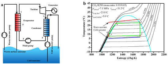
Figure 1.
The CO2−based binary zeotropic mixture power cycle, (a) flow chart (b) schematic diagram.
2.2. Modeling
The thermophysical parameters of a zeotropic mixture at a specified state can be obtained from REFPROP 9.0 [26] by inputting at least two known state parameters. Each state point of the mixed working fluid is calculated according to the following equations. The effect of the turbine is to expand the working fluid. With knowing the inlet state point, the outlet enthalpy can be calculated using Equation (1). Based on the above calculated enthalpy and the specified outlet pressure, the outlet state point and all of the parameters at this point can be obtained. The effect of the fluid pump is to pressurize the working fluid. Similar to the above method, the parameters at the fluid pump outlet are calculated using Equation (2).
The condensation process in the condenser can be expressed as Equation (3), and the evaporation process in the evaporator is expressed by Equation (4).
The power consumption of the fluid pump can be calculated using Equation (5). Similarly, the net power output of the turbine can be calculated using Equation (6). In addition, the net power output of the whole cycle can be calculated using Equation (7).
The flow chart of the CO2-based binary zeotropic mixture power cycle is shown in Figure 2. Based on the program, state points, operation parameters, and performance parameters can be obtained.
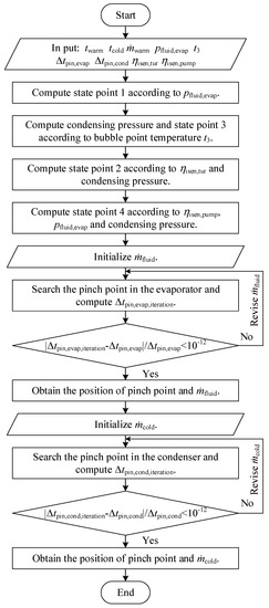
Figure 2.
Flow chart of the theoretical analysis program of the CO2−based binary zeotropic mixture power cycle.
2.3. Calculation Conditions
Before the calculation, some operation parameters need to be specified. The mass flow rate of warm seawater is 10.0 kg/s and the initial temperature is 27.0 °C. The initial temperature of cold seawater is 5.0 °C. The condensing temperature is 8.0 °C. The isentropic efficiency of both the pump and turbine is 85%. The pinch point temperature is specified as 2 °C for the condenser and evaporator. The range of the evaporating temperature is between 20.0 and 23.0 °C, with 0.5 °C step. Increasing the molar fraction of the secondary component of the mixed working fluid increases its flammability [27]. Considering this factor, the range of the molar fraction of the secondary component of the mixed working fluid is set from 0.01 to 0.05, with 0.01 step. It is noteworthy that only the 0.99/0.01 molar ratio of CO2/pentane is simulated because of the low critical point.
2.4. Discussion on Optimization of Objective Functions
Two new objective functions, the specific net power and specific volumetric flow, were proposed to measure the deficiencies of OTEC systems. The applications of thermal efficiency and the above objective functions are discussed below.
Thermal efficiency reflects the conversion extent from heat to power. It is an objective function by which all power cycles are evaluated and can be calculated using Equation (8). However, this objective function is unreasonable for OTEC systems. Improving the thermal efficiency of an OTEC system means improving the average endothermic temperature or reducing the average exothermic temperature, which leads to decreasing the thermal potential difference and heat exchange capability between the working fluid and seawater, finally leading to a decrease in the heat/cold recovery rate. On the other hand, the hot and cold seawater are both extracted by pumps, the power consumption of which is non-negligible. Therefore, the heating capacity of the surface hot seawater and the cooling capacity of the deep cold seawater should be entirely utilized. Blindly improving thermal efficiency without paying attention to the utilization of the cold and heat sources will cause a waste of energy. To sum up, thermal efficiency cannot be the only objective function for an OTEC system.
The specific net power is a new objective function that is defined in this article. It is the net power output corresponding to per unit mass flow rate of seawater and relates to the heat/cooling utilization rate of seawater. A higher specific net power indicates that the heat/cooling capacity of the seawater is being entirely utilized by the working fluid.
This study focused on the specific net power of the cold seawater. Cold seawater needs to be lifted from depths of 600 to 1000 m underwater to the surface in practical OTEC projects, which requires more power than pumping warm seawater. Therefore, cold seawater is more precious, and its cooling capacity should be more entirely utilized. The specific net power can be calculated using Equation (9). Except otherwise specified, the specific net power mentioned below refers to that of the cold seawater.
In some applications, it is more reasonable for an OTEC system to take the specific net power as the objective function, such as an onshore OTEC plant. Due to the location of the plant, it consumes extra power by pumping the cold seawater from the sea to the OTEC plant on the shore, which leads to more power consumption compared to offshore OTEC plants [28]. Therefore, for onshore OTEC plants, the utilization of cold seawater deserves more attention than the thermal efficiency. Thus, the specific net power can be considered as the objective function.
The specific volumetric flow is another new objective function that defined in this article. It refers to the volume flow corresponding to the per unit net power output at each state point. A lower specific volumetric flow indicates a lower volume flow of the working fluid required for the unit net power output, the optimization of which can be used to reduce the size of the equipment. The specific volumetric flow can be calculated using Equation (10).
This study focused on the specific volumetric flow at the evaporator outlet because the mixed working fluid is all saturated gas at this state point, and variations in specific volume with changes in conditions are more obvious than at other state points, which has an absolute effect on the turbine volume. As shown in Figure 3, using a 0.95/0.05 molar ratio of CO2/propane, the specific volume at the evaporator outlet decreased by 2.21% as the evaporating temperature increased from 22.5 to 23.0 °C. Under an evaporating temperature of 23.0 °C, the specific volume at the evaporator outlet decreased by 1.68% as the molar ratio decreased from 0.05 to 0.04. Unless otherwise specified, the specific volumetric flow mentioned below refers to the specific volumetric flow at the evaporator outlet.
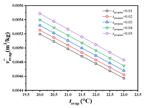
Figure 3.
Variations in specific volume at the exit of the evaporator.
In some applications, taking the specific volumetric flow as the objective function is the most suitable, such as offshore OTEC plants. The open sea contains abundant ocean thermal energy generally speaking, but the construction sites of offshore OTEC plants leads to high costs associated with platform positioning, construction, maintenance, and material transportation [28]. Reducing the size of the equipment can effectively reduce the above costs. Additionally, due to the harsh environment of offshore locations, the strength requirement for OTEC plant structures is also higher; thus, reducing the size of the equipment can improve its structural strength.
3. Results and Discussion
Based on the two proposed objective functions and thermal efficiency, the evaporating temperature of the CO2-based binary zeotropic mixture power cycle and the molar fraction of the secondary component of the mixed working fluid were optimized, the optimum objective function selected for the OTEC plant in different applications was obtained, and the suitable working fluid corresponding to each objective function was selected.
3.1. Parameter Optimization Based Thermal Efficiency as the Objective Function
As shown in Figure 4, the thermal efficiency of the CO2-based binary zeotropic mixture power cycle with different secondary components showed the same trend under the considered conditions. With increasing evaporating temperature or decreasing molar fraction of the secondary component of the working fluid, thermal efficiency increased monotonically.
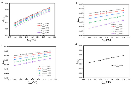
Figure 4.
Variations in cycle thermal efficiency, (a) CO2/propane; (b) CO2/butane; (c) CO2/isobutane; (d) CO2/pentane.
Under the considered conditions, the variation in thermal efficiency could be analyzed from the average endothermic temperature and mass flow rate of the working fluid. The two showed opposite trends with varying conditions. The effect of the mass flow rate on thermal efficiency could be ignored because of the lack of change. In other words, the average endothermic temperature plays the major role. With increasing evaporating temperature, the average endothermic temperature increased, which resulted in an increasing trend in thermal efficiency. With increasing molar fraction of the secondary component of the working fluid, the temperature glide of the working fluid increased. Due to its constant dew point temperature, the bubble point temperature shifted down along the liquid saturation curve, which led to a decrease in the average endothermic temperature as well as thermal efficiency.
Under the considered conditions, the thermal efficiency of this cycle was generally the highest with CO2/propane, followed by CO2/isobutane, CO2/butane, and CO2/pentane. Under an evaporating temperature of 23.0 °C and 0.99/0.01 molar ratio, the thermal efficiency of all the considered working fluids reached the maximum. The thermal efficiency of CO2/propane reached 0.3057, which was the maximum value among all working fluids. The thermal efficiency of CO2/pentane only reached 0.2421, which was the least ideal. With increasing molar fraction of the secondary component or decreasing evaporating temperature, the thermal efficiency difference between CO2/butane and CO2/propane increased, reaching a maximum thermal efficiency difference (0.0165) under 0.95/0.05 molar ratio and evaporating temperature of 20 °C. Under the same conditions, the thermal efficiency difference between CO2/isobutane and CO2/propane also reached the maximal value (0.0105).
3.2. Parameter Optimization Based on Objective Function of the Specific Net Power
The variation in specific net power was analyzed from the mass flow rate of the cold seawater and net power output of this cycle. The variations in the net power output are shown in Figure 5. Under most considered conditions, the net power output decreased with increasing evaporating temperature or decreasing molar fraction of the secondary component of the working fluid. It is worth noting that, under low evaporating temperature and high molar fraction of the secondary component, the variations in net power output showed opposite trends for CO2/butane and CO2/isobutane. The reason is revealed in the analysis below.
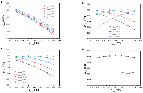
Figure 5.
Variations in net power output, (a) CO2/propane; (b) CO2/butane; (c) CO2/isobutane; (d) CO2/pentane.
The slip temperature difference of the mixed working fluids showed an increasing trend with increasing molar fraction of the secondary component, leading to increased thermal potential difference and heat exchange capacity between the warm seawater and working fluid, as well as the heat load of this cycle. Under a constant molar fraction of the secondary component, since the pinch point temperature of the evaporator and initial temperature of the warm seawater in the program were constant, the temperature of the warm seawater at the evaporator exit increased with increasing evaporating temperature, which decreased the heat load of this cycle. Due to the lack of obvious variations in thermal efficiency under most conditions, the variations in net power output were similar to those of heat load. Under a low evaporating temperature and high molar fraction of the secondary component, the reason for the opposite trends in net power output for CO2/butane and CO2/isobutane was due to the decreased variation in heat load, which led to heat load not playing a major role.
The variations in specific net power are shown in Figure 6. The specific net power increased with increasing evaporating temperature, and the variations in specific net power with increasing molar fraction of the secondary component were similar to those of the net power output. With increasing evaporating temperature, both the mass flow rate of the cold seawater and net power output decreased, but a large reduction was observed in the latter compared to the former. According to Equation (8), the specific net power increased. Due to non-significant variations in the mass flow rate of the cold seawater with increasing molar fraction of the secondary component, the variations in net power output had more impact on specific net power and displayed a similar variation trend.
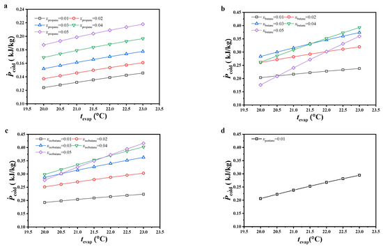
Figure 6.
Variations in specific net power, (a) CO2/propane; (b) CO2/butane; (c) CO2/isobutane; (d) CO2/pentane.
Under the considered conditions, the specific net power of CO2/propane was obviously lower than that of other working fluids. Under the considered evaporating temperature and 0.99/0.01 molar ratio, CO2/pentane had the maximum specific net power, followed by CO2/butane and CO2/isobutane. Under molar ratios of 0.98/0.02 and 0.97/0.03, the specific net power difference between CO2/butane and CO2/isobutane decreased with increasing evaporating temperature and molar fraction of the secondary component. The latter was even higher than the former under the conditions of 0.97/0.03 molar ratio and an evaporating temperature lower than 20.5 °C. Under molar ratios of 0.96/0.04 and 0.95/0.05, the specific net power for CO2/isobutane was higher than that for CO2/butane. Under an evaporating temperature of 23 °C and 0.95/0.05 molar ratio for CO2/isobutane, the specific net power reached a maximum value of 0.42 kJ/kg.
3.3. Parameter Optimization Based on Objective Function of the Specific Volumetric Flow
As shown in Figure 7, the specific volumetric flow increased with decreasing evaporating temperature or molar fraction of the secondary component. The variations in specific volumetric flow were analyzed from the net power output and volume flow at the evaporator outlet. As mentioned earlier, the specific volume of the gaseous working fluid at the evaporator outlet decreased with increasing evaporating temperature or molar fraction of the secondary component. It changed greatly compared to the net power output and played a greater role in determining the specific volumetric flow, which led to variations in specific volumetric flow showing the same trend.
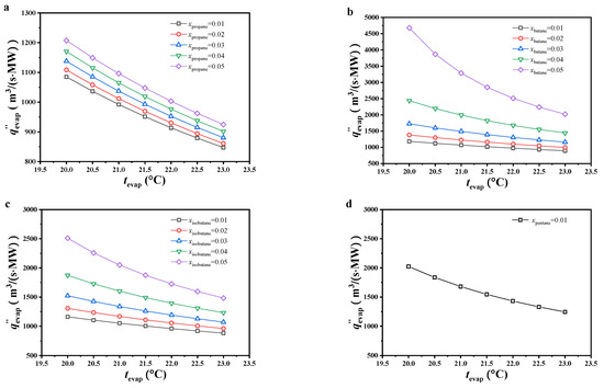
Figure 7.
The variation of the specific volumetric flow ((a) CO2/propane; (b) CO2/butane; (c) CO2/isobutane; (d) CO2/pentane).
Under 0.99/0.01 molar ratio and the considered evaporating temperature, the specific volumetric flow of CO2/pentane was the highest, followed by CO2/butane, CO2/isobutane, and CO2/propane. Under other considered conditions, the specific volumetric flow of CO2/butane was obviously higher than that of CO2/isobutane and CO2/propane, with CO2/propane being ideal. Under 0.99/0.01 molar ratio for CO2/propane and an evaporating temperature of 23 °C, the specific volumetric flow reached a minimum value of 847.15 m3/(s·MW).
3.4. Discussion on the Selection of Working Fluid
Under the considered conditions, the thermal efficiency of CO2/propane was generally higher than that of other working fluids. In the case where an OTEC system has specific requirements for thermal efficiency, it should take thermal efficiency as the objective function. At this point, CO2/propane is recommended as the working fluid.
From the above discussion, it can be concluded that it is unreasonable for an OTEC system to only take thermal efficiency as the objective function. Only pursuing thermal efficiency is of no benefit to entirely using the cooling capacity of cold seawater. In the case where an onshore OTEC plant has no special requirements for thermal efficiency, specific net power can be considered as the objective function. Under the considered evaporating temperature, the specific net powers of CO2/butane and CO2/isobutane were ideal, especially under a high molar fraction of organics in the working fluid. It is recommended to use CO2/butane (0.97/0.03 or 0.96/0.04 molar ratio) or CO2/isobutane (0.97/0.03, 0.96/0.04, or 0.95/0.05 molar ratio) as the working fluid.
In some applications, an OTEC plant needs to reduce the equipment size in order to obtain maximum economic benefits. In this case, the OTEC plant can consider specific volumetric flow as the objective function, such as offshore OTEC plants. The construction and maintenance costs of offshore OTEC plants are higher than those of other types, and reducing the equipment size is conducive to cost savings. In addition, the smaller equipment size helps improve the structural strength of the system to better handle the harsh marine environment. In the case where an OTEC system takes specific volumetric flow as the objective function, CO2/propane is recommended as the working fluid under the considered conditions.
In addition, the selection of the working fluid still needs to comprehensively consider the commercial feasibility of the project. It is worth noting that CO2/pentane shows poor performance based on the proposed objective functions, so it is generally not recommended as a working fluid.
4. Conclusions
Considering the different applications of OTEC systems, two new objective functions were proposed and discussed, along with thermal efficiency. The applications of each objective function were considered. Based on the above proposed objective functions, the performance of the CO2-based binary zeotropic mixture power cycle was further investigated.
(1) It is unreasonable to only take thermal efficiency as the objective function for OTEC systems. The objective function for OTEC systems should be determined according to the specific requirements or specific application in order to obtain the greatest benefit. To maximize energy utilization of seawater, specific net power should be taken as the objective function. To reduce equipment size, specific volumetric flow should be taken as the objective function.
(2) Thermal efficiency increases with increasing evaporating temperature and decreasing molar fraction of the secondary component of the working fluid. The variations in specific volumetric flow were opposite to the variations in thermal efficiency. The specific net power increased with increasing evaporating temperature, and specific net power had a similar variation trend as that of net power output with increasing molar fraction of the secondary component of the working fluid.
(3) In the case where the OTEC system takes thermal efficiency as the objective function, CO2/propane under the considered molar ratio can be considered as the working fluid. In the case where the OTEC system takes specific net power as the objective function, CO2/butane (0.97/0.03 or 0.96/0.04 molar ratio) or CO2/isobutane (0.97/0.03, 0.96/0.04, or 0.95/0.05 molar ratio) can be selected as the working fluid, such as an onshore OTEC plant. In the case where the OTEC system takes specific volumetric flow as the objective function, CO2/propane under the considered mole ratio can be considered as the working fluid, such as an offshore OTEC plant.
Author Contributions
Conceptualization, L.P.; methodology, W.S.; software, Y.S. and L.P.; investigation, W.S., Y.S. and L.S.; writing—original draft preparation, Y.S. and L.S.; writing—review and editing, W.S., L.P. and X.W.; project administration, X.W., funding acquisition, L.P. All authors have read and agreed to the published version of the manuscript.
Funding
This research was funded by [National Natural Science Foundation of China] grant number [51776215] and [Beijing Natural Science Foundation] grant number [3192042].
Institutional Review Board Statement
Not applicable.
Informed Consent Statement
Not applicable.
Data Availability Statement
No new data were created or analyzed in this study.
Acknowledgments
Project 51776215 supported by National Natural Science Foundation of China is gratefully acknowledged. The authors are also grateful for the support of Beijing Natural Science Foundation (3192042).
Conflicts of Interest
The authors declare no conflict of interest.
Nomenclature
| mass flow rate (kg/s) | |
| p | power (kW) |
| specific net power (kJ/kg) | |
| q | specific volumetric flow (m3/(s·MW)) |
| heat load (kW) | |
| t | temperature (°C) |
| v | specific volume (m3/kg) |
| V | volume flow (m3/(s·MW)) |
| η | efficiency |
| subscript | |
| bubble | bubble point |
| cold | deep cold seawater |
| cond | condense |
| c | critical |
| dew | dew point |
| evap | evaporate |
| fluid | working fluid |
| isen | isentropic |
| net | net power output |
| pin | pinch point |
| pum | pump |
| ther | thermal |
| tur | turbine |
| warm | surface warm seawater |
| 1, 2, 3, 4, 5 | state points of working fluid |
| superscript | |
| ′ | inlet |
| ″ | outlet |
References
- Rajagopalan, K.; Nihous, G.C. Estimates of global Ocean Thermal Energy Conversion (OTEC) resources using an ocean general circulation model. Renew. Energy 2013, 50, 532–540. [Google Scholar] [CrossRef]
- D’Arsonval. Utilisation de forces naturelles. Rev. Sci. 1881, 17, 370–372. [Google Scholar]
- Claude, G. Power from the tropical seas. Mech. Eng. 1930, 52, 1039–1044. [Google Scholar]
- Waid, R.L. The mini-OTEC test. In Proceedings of the OCEANS ’79, San Diego, CA, USA, 17–19 September 1979; pp. 26548–26552. [Google Scholar]
- Mitsui, T.; Ito, F.; Seya, Y.; Nakamoto, Y. Outline of The 100 kw Otec Pilot Plant In The Republic of Naure. IEEE Trans. Power Appar. Syst. 1983, PAS-102, 3167–3171. [Google Scholar] [CrossRef]
- The Okinawa Prefecture Ocean Thermal Energy Conversion Power Demonstration Project. Available online: http://otecokinawa.com (accessed on 8 March 2022).
- Makai Connects World’s Largest Ocean Thermal Plant to U.S. Grid. August 2015. Available online: http://www.makai.com/makai-news/2015_08_29_makai_connects_otec/ (accessed on 8 March 2022).
- Aydin, H.; Lee, H.-S.; Kim, H.-J.; Shin, S.K.; Park, K. Off-design performance analysis of a closed-cycle ocean thermal energy conversion system with solar thermal preheating and superheating. Renew. Energy 2014, 72, 154–163. [Google Scholar] [CrossRef]
- Nihous, G.C. An Order-of-Magnitude Estimate of Ocean Thermal Energy Conversion Resources. J. Energy Resour. Technol. 2005, 127, 328–333. [Google Scholar] [CrossRef]
- Wu, Z.; Feng, H.; Chen, L.; Tang, W.; Shi, J.; Ge, Y. Constructal thermodynamic optimization for ocean thermal energy conversion system with dual-pressure organic Rankine cycle. Energy Convers. Manag. 2020, 210, 112727. [Google Scholar] [CrossRef]
- Samsuri, N.; Sazali, N.; Jamaludia, A.S.; Razali, N.N.M. Simulation Modeling The Performance of Ocean Thermal Energy Conversion Power Cycle. IOP Conf. Ser. Mater. Sci. Eng. 2021, 1062, 012034. [Google Scholar] [CrossRef]
- Vera, D.; Baccioli, A.; Jurado, F.; Desideri, U. Modeling and optimization of an ocean thermal energy conversion system for remote islands electrification. Renew. Energy 2020, 162, 1399–1414. [Google Scholar] [CrossRef]
- Chen, F.; Liu, L.; Peng, J.; Ge, Y.; Wu, H.; Liu, W. Theoretical and experimental research on the thermal performance of ocean thermal energy conversion system using the rankine cycle mode. Energy 2019, 183, 497–503. [Google Scholar] [CrossRef]
- Yoon, J.-I.; Seol, S.-H.; Son, C.-H.; Jung, S.-H.; Kim, Y.-B.; Lee, H.-S.; Kim, H.-J.; Moon, J.-H. Analysis of the high-efficiency EP-OTEC cycle using R152a. Renew. Energy 2017, 105, 366–373. [Google Scholar] [CrossRef]
- Ikegami, Y.; Yasunaga, T.; Morisaki, T. Ocean Thermal Energy Conversion Using Double-Stage Rankine Cycle. J. Mar. Sci. Eng. 2018, 6, 21. [Google Scholar] [CrossRef]
- Liu, W.; Xu, X.; Chen, F.; Liu, Y.; Li, S.; Liu, L.; Chen, Y. A review of research on the closed thermodynamic cycles of ocean thermal energy conversion. Renew. Sustain. Energy Rev. 2020, 119, 109581. [Google Scholar] [CrossRef]
- Uehara, H. OTEC system using a new cycle with absorption and extraction process. In Proceedings of the 12th International Conference on the Properties of Water and Steam, Orlando, FL, USA, 11 September 1994. [Google Scholar]
- Dhanak, M.; Xiros, N. Springer Handbook of Ocean Engineering; Springer International Publishing: Cham, Switzerland, 2016. [Google Scholar]
- Yuan, H.; Mei, N.; Zhou, P. Performance analysis of an absorption power cycle for ocean thermal energy conversion. Energy Convers. Manag. 2014, 87, 199–207. [Google Scholar] [CrossRef]
- Li, C.; Pan, L.; Wang, Y. Thermodynamic optimization of Rankine cycle using CO2-based binary zeotropic mixture for ocean thermal energy conversion. Appl. Therm. Eng. 2020, 178, 115617. [Google Scholar] [CrossRef]
- Yang, M.-H.; Yeh, R.-H. The investigation of optimum multi-component blends in organic Rankine cycle for ocean thermal energy conversion. Appl. Therm. Eng. 2022, 217, 119279. [Google Scholar] [CrossRef]
- Peng, J.; Ge, Y.; Chen, F.; Liu, L.; Wu, H.; Liu, W. Theoretical and experimental study on the performance of a high-efficiency thermodynamic cycle for ocean thermal energy conversion. Renew. Energy 2022, 185, 734–747. [Google Scholar] [CrossRef]
- Gao, E.; Cui, Q.; Jing, H.; Zhang, Z.; Zhang, X. A review of application status and replacement progress of refrigerants in the Chinese cold chain industry. Int. J. Refrig. 2021, 128, 104–117. [Google Scholar] [CrossRef]
- Harby, K. Hydrocarbons and their mixtures as alternatives to environmental unfriendly halogenated refrigerants: An updated overview. Renew. Sustain. Energy Rev. 2017, 73, 1247–1264. [Google Scholar] [CrossRef]
- Pan, L.; Wei, X.; Shi, W. Performance analysis of a zeotropic mixture (R290/CO2) for trans-critical power cycle. Chin. J. Chem. Eng. 2015, 23, 572–577. [Google Scholar] [CrossRef]
- Lemmon, E.W.; Huber, M.L.; Mclinden, M.O. NIST Standard Reference Database 23, Reference Fluid Thermodynamic and Transport Properties (REFPROP), Version 9.0; National Institute of Standards and Technology: Gaithersburg, MD, USA, 2010. [Google Scholar]
- Pan, L.; Ma, Y.; Li, T.; Li, H.; Li, B.; Wei, X. Investigation on the cycle performance and the combustion characteristic of two CO2-based binary mixtures for the transcritical power cycle. Energy 2019, 179, 454–463. [Google Scholar] [CrossRef]
- Su, J.; Zeng, H.; Xiao, G.; Wang, J.; Jiang, J. Research status and prospect of ocean thermal energy conversion technology. China Offshore Oil Gas 2012, 24, 84–98. [Google Scholar]


Disclaimer/Publisher’s Note: The statements, opinions and data contained in all publications are solely those of the individual author(s) and contributor(s) and not of MDPI and/or the editor(s). MDPI and/or the editor(s) disclaim responsibility for any injury to people or property resulting from any ideas, methods, instructions or products referred to in the content. |
© 2023 by the authors. Licensee MDPI, Basel, Switzerland. This article is an open access article distributed under the terms and conditions of the Creative Commons Attribution (CC BY) license (https://creativecommons.org/licenses/by/4.0/).