1. Introduction
As part of a ship’s environmentally friendly policy, active research is being conducted on energy storage systems (ESS) for ships.
Such ESS has a major influence on determining the propulsion and operating system of the ship in the future.
A separate space must be provided for the ESS, but small- and medium-sized ships often require it to be located at the bottom of the ship to make use of the space.
If the ESS is placed on the bottom of the ship, the slamming impact load should be considered, and a study of the vibrations generated during the slamming impact is required.
In addition, the test standards of each classification for the installation of ESS in ships are currently accumulating cell unit tests, module unit tests, and system unit test standards. The focus is on battery fire and performance tests, and there is no standard for external effects on batteries. As mentioned earlier, in the case of small- and medium-sized ships, the ESS is located at the bottom of the ship, and in this case, it is exposed to the shock and vibration caused by the slamming load.
When ships undertake a voyage with slamming phenomena, structural damage often occurs. As ships have recently become larger and faster than in the past, impulsive pressure loading caused by slamming can be dramatically greater, therefore, the importance of structural design has increased.
Most studies have focused on the accurate estimation of the maximum pressure during slamming [
1]. The plate thickness of the ship was still calculated using the equivalent design pressure based on the peak measurement of slamming pressure. The plate thickness is calculated by considering the equivalent design pressure based on the measured slamming pressure peak, and several experimental and theoretical studies have been conducted to estimate the exact value of the peak pressure [
2]. However, according to recent studies, structural damage is affected not only by the peak pressure but also by the peak width in the time interval of the peak pressure.
In general, when the duration of the pressure is less than 1, the behavioral characteristics of the structure are determined by the idealized pressure value (impulse) regardless of the peak pressure and duration. On the other hand, when the duration of the pressure is greater than 1, the behavioral characteristics of the structure are determined by the peak pressure. However, if the duration of the pressure is similar to the natural period of the structure, the behavioral characteristics of the structure are affected by both the peak pressure and the duration [
2].
Slamming phenomena in offshore structures can be largely classified into four types. Slamming by breaking waves, which occurs when waves break when the ratio of wave height to wavelength is 1:7, horizontal slamming, which is generated by coupling the heave motion and pitch motion of a structure, and the waves on the outer wall of the structure wave run-up slamming, which occurs while riding up, can be called bottom slamming, in which waves hit the bottom of a structure.
Many researchers have pointed out that, even if the tests are performed under the same drop conditions, the measured peak pressures can be different due to the uncertainty of the slamming phenomenon. However, quantification of the uncertainty has not been reported in the literature. Therefore, if this uncertainty is to be considered in the design process, the test condition must be quantified.
The problem of slamming is still overly complicated because the wedge shape is simple, but the flow area is not predetermined [
3,
4]. Therefore, even if the test is performed under the same drop conditions, the measured peak pressures may differ due to the uncertainty in the impact pressure load caused by slamming [
5,
6]. However, there are no criterion for testing to resolve uncertainty.
In this study, the test was performed by repeated dropping into the water using structural bottom angles of 0°, 3°, 10°, and 20° to the free surface of the water. The peak pressure, peak width, impulse, pressure coefficient, and traveling velocity of the peak pressure obtained from repeated tests were estimated using the mean and coefficient of variation (COV).
2. Methods and Experiment
For the slamming test, a drop test device was installed in a tank with a length and width of 2.5 m and a water depth of 1 m. The height of the test model can be adjusted up to 0.5 m from the free surface of the water. The drop test was performed at 0.1 m intervals of 0.1 m to 0.5 m, and the drop occurs when the current of the electromagnet is cut off.
Figure 1 shows the test model installed in the slamming equipment.
The wedges had a length of 1000 mm, a width of 600 mm, and a height of 400 mm, and each weight was 60 kgf. The wedge dimensions are shown in
Figure 2 and
Table 1. The wood wedges had a bottom plate thickness of 50 mm and were assumed to be rigid. The steel wedges had a bottom plate thickness of 3 mm, 4 mm, 5 mm, and 6 mm, and are assumed to be elastic. The actual model is shown in
Figure 3.
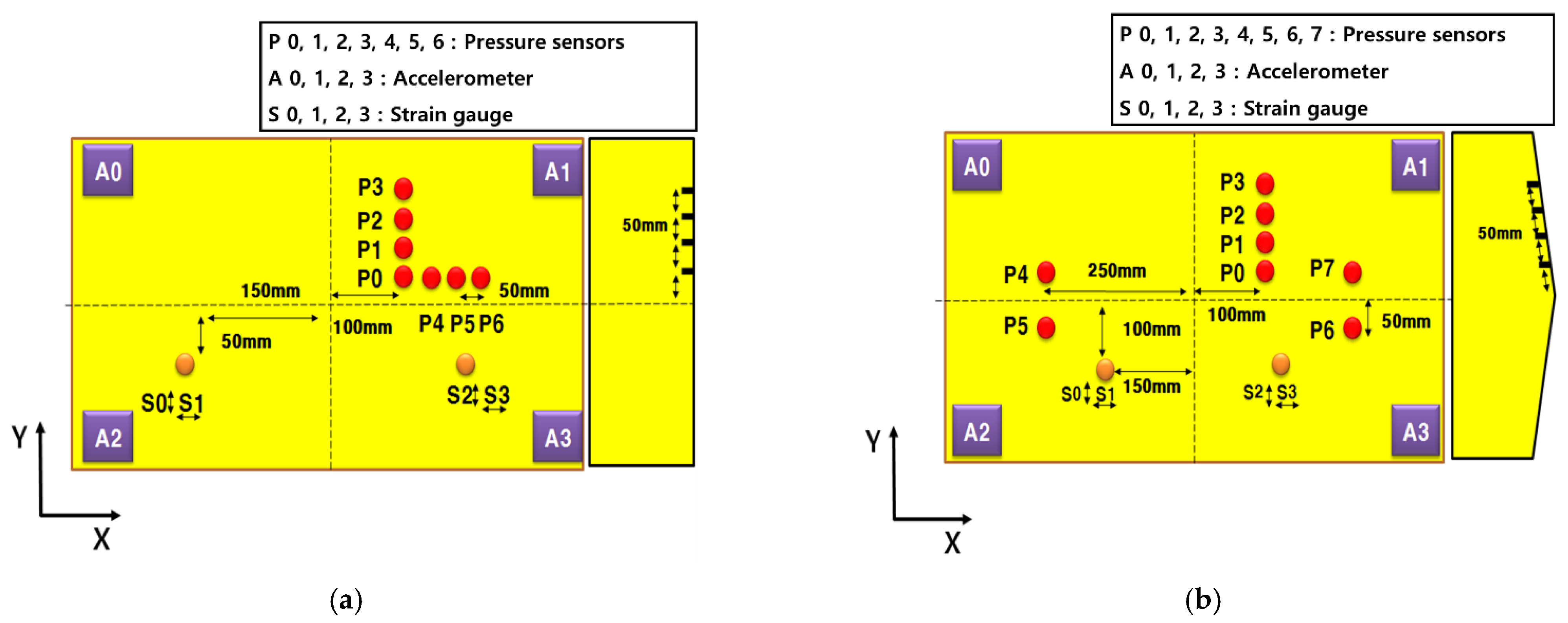
The locations of each sensor are shown in
Figure 4. Red P0–P7 is the location of the pressure sensor, A0–A3 are the positions of the accelerometer, and the orange part is the strain gauge. The pressure sensor was installed in the surface of the model 100 mm from the center of the model and 50, 100, 150, and 200 mm from the centerline of the model. An accelerometer was installed on the interior inside bottom floor of the model at the corners. The strain gauge was installed symmetrically 150 mm from the center of the model.
With the same drop-in height and angle, each experiment was repeated five times for the deadrise angle. The drop height was increased by 100 mm to 100–500 mm for each test. The experiment was performed by changing the thickness and deadrise angle given in
Table 1.
Figure 5 shows the results of the measured velocity in the case of deadrise angle 0° and drop height of 500 mm. At a drop height of 500 mm, the theoretical velocity was 3.13 m/s. However, the actual velocity is 3.03 m/s.
Figure 5 shows the obtained margin of error of approximately 3%. This error is often caused by the friction between the guide rails and ball bearings or is considered negligible.
3. Experimental Results
The slamming shock pressure can be idealized, as shown in
Figure 6 [
3]. In numerical analyses, the long tail is not pressurized [
3,
6], and the effect on the extent of the damage reaches almost negligible levels [
5].
3.1. Air Effect
Even for the same condition, the result of impulsive pressure loading in the 0° steel wedge shows a different phenomenon from that in the 0° wood wedge model. Normally, wedge models hit the free surface once after oscillating.
As
Figure 7a shows, the first large peak occurred and the second peak is quite large because of the air effect. Moreover, the peak becomes smaller with time and finally disappears. Then, pressure occurs over a long period.
As
Figure 8a shows, only one peak was observed in the 0° wood wedge model. However, the pressure results of the steel-wedge model showed several peak pressures.
This can be attributed to the air effect and natural frequency of the plate [
6]. In the case of wood, the air effect does not occur because there is no elastic effect. However, in the case of steel, the air effect is issued under the influence of elasticity, and its period coincides with the natural period of the structure, and this air effect shows several pressure peaks.
3.2. Peak Pressure
Figure 9a–d shows the comparison peak pressures at deadrise angles 0°, 3°, 10°, and 20°.
Figure 9a shows the maximum pressure as a function of the dropping speed of a model made of wood and steel with thicknesses of 3, 4, and 5 mm on the bottom side at a deadrise angle of 0°. The free-drop height was 100–500 mm, with an interval of 100 mm.
It was confirmed that as the drop height increased, the drop speed increased and the maximum pressure increased accordingly. The singularity is that the maximum pressure increases with increasing thickness of the bottom, even though the experiment was performed with the same mass. For wood, which is assumed to be rigid, the maximum pressure was measured to be the highest, and for steel, it was confirmed that the air effect occurred due to the elastic effect.
This means that multiple pressures due to the air effect occur simultaneously at one pressure peak, as shown in
Figure 7a, and it was confirmed that the maximum pressure due to this air effect was measured lower than the model with a dead-rise angle of 3° to 10° [
7].
Figure 9b–d shows the maximum pressure as a function of the dropping speed of a model made of wood and steel with thicknesses of 3, 4, and 5 mm at the bottom at a deadrise angle of 3°. As the drop height increased, the drop speed increased, and the maximum pressure increased significantly. The singularity is that the maximum pressure increases with increasing thickness of the bottom, even though the experiment was performed with the same mass as the angle formed by the angle of the free surface of 0° [
8]. In the case of wood assumed to be rigid, the maximum pressure was measured to be the highest, and the maximum pressure was measured to be significantly higher than the angle formed by the angle of the free water surface at 0°.
When the angle formed with the free water surface is 0°, the pressure value is canceled due to the air effect caused by the elastic effect, whereas when the angle formed with the free surface angle is 3°–20°, the elastic effect works, but the air effect is not formed, so the pressure value is increased.
When the deadrise angle is 0 degrees, the pressure is lower than other deadrise angles due to the air effect caused by the elastic effect. When the deadrise angle is 3 degrees, the air effect does not occur, and the largest pressure is generated because the mass of water to be pushed out, that is, the amount of add mass, is greater than 10 to 20 degrees.
In the case of a deadrise angle of 10°, although a large pressure was not measured compared to the angle between the free surface and the free surface of 3°, it is generally reported that the angle between the free surface and the angle of 3° to 10° is the largest pressure value.
3.3. Peak Strain
Figure 10a–d shows the maximum strain value as a function of the dropping speed of a model manufactured with a thicknesses of 3, 4, and 5 mm on the bottom with deadrise angles of 0°, 3°, 10°, and 20°. The free-drop height was 100–500 mm with an interval of 100 mm. As the drop height increased, the strain value increased, and it shows that the thinner the thickness, the larger the value produced. Although the magnitude of the maximum pressure tends to be relatively large, the strain value shows no significant difference compared to the experimental value of the deadrise angle of 0°.
3.4. Peak Width
Figure 11a–d shows the comparison of peak widths between deadrise angles 0°, 3°, 10°, and 20°.
Figure 11a shows the width of the maximum pressure as a function of the dropping speed of the wood and steel models at a deadrise angle of 0°. The free-drop height was 100–500 mm, with an interval of 100 mm. The characteristics of the elastic effect in a model made of rigid wood and steel are not clearly visible. Compared with the width of the measured maximum pressure of the steel model, the width of the maximum pressure decreases with increasing drop height, and with increasing thickness, the width of the maximum pressure tended to decrease. Because the impulse value, which is the idealized value of the slamming pressure, is calculated based on the maximum pressure and the width of the maximum pressure, the width of the pressure is very small because it occurs in a short amount of time, but it is one of the most important measurement elements.
Figure 11b shows the width of the maximum pressure as a function of the dropping speed of the wood and steel models with thicknesses of 3, 4, and 5 mm at the bottom at a dead-rise angle of 3°. The width of the pressure difference between the rigid wood and steel models was relatively high. Comparing the measured maximum pressure widths of the steel model, the greater the air drop height, the smaller the maximum pressure width and thickness.
Figure 11c shows the maximum pressure width according to the dropping speed of the wood and steel models with thicknesses of 3, 4, and 5 mm at the bottom with a dead-rise angle of 10°. In the case of the steel model, which is an elastic model, the pressure width as a function of the thickness was measured to be relatively low, and it was confirmed that the width of the maximum pressure decreases with increasing drop height increases. Wood, which is a rigid model, shows ranges of values between 4 and 5 mm in thickness.
Figure 11d shows the width of maximum pressure as a function of the dropping speed of the wood and steel models with thicknesses of 3, 4, and 5 mm at the bottom with a dead-rise angle of 20°. In the case of the steel model, which is an elastic model, the pressure width as a function of the thickness was measured to be relatively low, and it was confirmed that the width of the maximum pressure decrease with increasing drop height increases. Because the impulse value, which is the idealized value of the slamming pressure, is calculated based on the maximum pressure and the width of the maximum pressure, the width of the pressure is very small because it occurs in a short time, but it is one of the most important measurement elements.
3.5. Impulse
Figure 12a–d shows the comparison impulse between deadrise angles 0°, 3°, 10°, and 20°.
Figure 12a shows the impulse value as a function of the dropping speed of the wood and steel models at the bottom with a deadrise angle of 0°. The free-drop height was 100–500 mm, with an interval of 100 mm. It is determined by calculating the area of pressure based on the measured maximum pressure and width of the maximum pressure. The maximum pressure and the duration of the pressure indicate the load acting on the structure. Even if the maximum pressure is relatively high if the duration is short or long, even if the maximum pressure is relatively small, the impulse value may be the same, and the factors acting on the structure are also different. In the study of slamming, the impulse value, including the duration of the load applied to the structure and the maximum pressure, is an important variable.
Figure 11 shows that the impulse value increases with increasing free drop height, and the values excluding wood showed no significant difference.
Figure 12b shows the impulse value according to the dropping speed of a model made of wood and steel with thicknesses of 3, 4, and 5 mm at the bottom with a dead-rise angle of 3°. At a deadrise angle of 0°, the impulse value tends to increase with increasing free drop height, but it can be seen that the values excluding the rigid wood model do not show any significant difference. This is because in impulse, where the duration of pressure is an important variable, it is difficult to measure the width when the deadrise angle is 0° due to the air effect, but when the deadrise angle is 3°, the pressure increase is very steep. Because the pressure drop is clearly indicated, the width of the pressure can be measured more accurately; thus, the area of the pressure is relatively easy to determine.
Figure 12c shows the impulse value as a function of the dropping speed of the wood and steel models with thicknesses of 3, 4, and 5 mm on the bottom at a dead-rise angle of 10°. At a deadrise angle of 0°, the impulse value was also larger with the increasing thickness of the rigid wood model. At a dead-rise angle of 3°, it was confirmed that the impulse value of steel, except for wood, had a constant value regardless of the dropping speed and the thickness of the base. At a deadrise angle of 10°, the impulse values tended to be reversed. As the dropping speed increases, the impulse value also increases; however, as the thickness of the base decreases, the value tended to increase.
Figure 12d shows the impulse value as a function of the dropping speed of the wood and steel models with thicknesses of 3, 4, and 5 mm on the bottom at a deadrise angle of 20°. At a deadrise angle of 0°, the impulse value was also larger as the thickness of the rigid model of wood and increased. At a dead-rise angle of 3°, it was confirmed that the impulse value of steel, except for wood, showed a constant value regardless of the dropping speed and the thickness of the base. At a deadrise angle of 10°, the impulse values tended to be reversed. As the dropping speed increases, the impulse value also increases; however, as the thickness of the base decreases, the value tended to increase.
3.6. Coefficient of Pressure
Coefficient of pressure is defined by the following Equation (1).
Pp: Peak pressure
ρ: Density of the fluid (1000 kg/m2)
Cp: Coefficient of pressure
V: Entry velocity
Figure 13a–d shows the coefficient of pressure value obtained by using the above Equation (1). The measured maximum pressure or strain value increases as the dropping speed increases. It is a non-dimensionalized value using the maximum pressure, and although there is a difference depending on the thickness of the model, it can be confirmed that the difference in the value is not large and relatively constant [
9]. Such a pressure coefficient can be used to determine the maximum pressure regardless of constraints, such as the experimental method or the size of the model.
Although there is a difference in the pressure coefficient according to the thickness, it shows a relatively constant value regardless of the dropping speed, except when the dropping speed was 1.4 m/s. Such a pressure coefficient can be used to obtain the maximum pressure regardless of constraints, such as the experimental method or the size of the model [
10].
3.7. Calculation Steel Plate of Natural Frequency
The experimental, theoretical, and numerical values of the natural frequency were calculated in each way. First, the natural frequency in air can be calculated as Equation (2), a simple expression of the unique [
11]:
a = panel length (mm)
b = panel breadth (mm)
t = plate thickness (mm)
The numerical method provides results from MSC Nastran. More information about the use of the acceleration sensor and impact hammer as well as the experimental in air is shown in
Table 2 and
Figure 14. The results of the experiments with 8 Hz differ because the structure and steel plate were not perfectly connected, so the results were lower than predicted.
When you are in contact with air versus the water surface, the water mass added to the edition has a natural frequency that leads to the additional Equations (3)–(5), which can be easily calculated [
12,
13].
a = width of plate
b = length of plate
β = aspect ratio dependent factor
αij = a function of model indices and boundary condition on plate
zij = dimensionless mode shape of i j mode
The peak values of the pressure and strain appear at 39.38 Hz, as listed in
Table 3, and this frequency is identical to the natural frequency calculated previously. From this, it can be seen that the structural behavior influences the pressure.
The natural frequencies of the steel plate in air and water were calculated, and the change in natural frequencies with changing drop heights was confirmed.
Figure 15 shows the power spectra of acceleration when the impact hammer hit the wedge of deadrise angle 0° mounted on the slamming frame on the water. The results for drop heights of 100, 300, and 500 mm are listed in
Table 4. The natural frequency decreased from 35 Hz to 32 Hz with increasing drop height. This is because the added mass due to slamming increased with increasing drop height.
3.8. Application to Ship Structure Design
To date, the maximum pressure for slamming has been calculated as the equivalent design pressure for the ship thickness. However, as a design variable, the impulse value considering the natural period of the structure and the width of the pressure can be the impact pressure. When the natural period of the structure is greater than the width of the pressure, the design variable becomes the peak pressure. If the natural period of the structure is smaller than the width of the pressure, the impulse value can be calculated as a design variable. It can be used to prevent damage to ships or offshore structures by proposing an equivalent static pressure coefficient by estimating the impulse value using the above-mentioned test formula [
14].
In this chapter, structural design formulae are proposed that can be applied to the 0° wedge model. As shown in
Figure 16, the impulse can be transformed into an equivalent static pressure.
Figure 16.
Power spectra of acceleration of wedges dropped from different drop heights.
Figure 16.
Power spectra of acceleration of wedges dropped from different drop heights.
ka = correction factor for aspect ratio of plate field
kr = correction factor for curved plates with stiffening direction
s = stiffener spacing
tk = corrosion addition
f1 = 1material factor depending on material strength group
psl = design pressure
The final result, as shown in
Figure 17, can be derived and used in the formula considering the duration of the pressure and the natural period of the structure. These results can solve the problem of insufficient information in estimating the slamming impact pressure. The coefficients of the following equations refer to chapters 1 and 6 of the Royal Institution of Naval Architects (RINA) [
15]. Considering the maximum pressure and duration of pressure as basic design parameters for the prevention of structural damage, the duration of pressure is the relationship between peak pressure, duration, and impulse corresponding to the design parameters to satisfy the following thickness estimation in structural Equation (6); if the period is shorter than the period, the information about the insufficient variable can be solved with the impulse value [
16]. The design equation for the design pressure can be estimated if the strain and period can be estimated.
So far, the structural formula has been proposed using the equivalent static pressure converted from the maximum pressure. However, the equivalent static pressure due to an impulse with a pressure width smaller than the natural period of the structure, as shown in
Figure 18a,b, has not been presented. In this section, the structural design formula for a flat plate is proposed, which is defined as the relationship between the maximum pressure and impulse value, as shown in
Figure 18c.
4. Conclusions
In this study we performed a free drop test. We compared and tested steel and wood wedge models with different deadrise angles at different drop heights.
Before the pre-drop test, the effects of the sampling rate and pressure sensor were compared, and the experimental setup was fully installed. Nevertheless, the underwater impact test is described probabilistically due to the uncertainty of the slamming phenomenon in the test [
17].
Impulse pressure loads due to slamming are classified into five categories: peak pressure, peak width, impulse and pressure coefficient, and movement speed of the peak pressure [
18]. Each result was examined as the mean and COV of the table. The following conclusions were drawn:
The slamming load acting on the structure is the smallest at 0° due to the elastic effect. The air effect is generated by the elastic effect and the pressure is reduced by forming an air effect. In addition, it was confirmed through tests that the pressure period matched the natural frequency of the structure.
It was confirmed that the period of the pressure and the period of the peak coincided with the natural frequency of the structure. This has been proven through experiments, hammer tests, and theoretical formulas.
Almost all COV values were between 1 and 15, and the uncertainty was small. However, COVs using small 3 and 10° wedge models give different results due to experimental errors, such as real dead-rise angles and their interaction with fluid fluctuations.
The peak point movement velocity indicates a fairly small COV. As the drop height increases, the peak point movement speed increases.
The formula can be derived from the impact pressure load information based on the calculated ship’s approach speed.
In this study, a formula is presented for the equivalent static pressure that is changed by an impulse with a peak width smaller than the structural period.
These results can solve the problem of the lack of information on the impact pressure load. The results of this study will be helpful in developing structural design procedures by considering the impact pressure as a fundamental design variable to prevent structural damage. The maximum pressure and impact can vary depending on the structural design, and the maximum width is the standard for the structural design. The peak pressure was calculated using the CP (pressure coefficient) formula. Moreover, the peak point movement speed is useful for the structural analysis. In addition, these results can be used in structural design formulas by comparing the peak widths and the natural duration of the structures. Therefore, it is expected that the improved results can prevent structural damage to marine structures and ships.


