Article

Study on Evolution Characteristics of Gas–Liquid Interaction in a New Gas-Curtain Launcher

1
School of Energy and Power Engineering, Nanjing University of Science and Technology, Nanjing 210094, China
2
The Third Research Department, Xi’an Modern Chemistry Research Institute, Xi’an 710065, China
*
Author to whom correspondence should be addressed.
J. Mar. Sci. Eng. 2023, 11(1), 55; https://doi.org/10.3390/jmse11010055
Submission received: 3 December 2022 / Revised: 26 December 2022 / Accepted: 28 December 2022 / Published: 30 December 2022
(This article belongs to the Section Ocean Engineering)

Abstract

:
For the new idea of a gas-curtain launcher with a grooved tube, the gas-curtain flow field and interior ballistic characteristics are mainly investigated in this paper. The coupling of the gas–liquid interaction model and interior ballistic equations is realized by solving the gas flow equation. Analyses have focused on the morphological evolution of the gas-curtain, pressure distribution, turbulence intensity evolution, and interior ballistic performance. The results show that multiple groove jets first expand independently of each other, and their shape changes from rectangular to triangular. The groove jets then come into contact with each other and form a gas-curtain. Meanwhile, the gas-curtain expansion results in complex changes in the pressure and turbulence intensity of the flow field in the tube. The parameters distribution in the flow field gradually have a simple tendency as the gas-curtain increases and the projectile moves. The moment the projectile starts moving, the gas volume fraction reaches 83%, indicating that the gas-curtain has made remarkable achievements in drag reduction. Significantly, under the calculated conditions in this paper, an initial velocity of 360.58 m/s was obtained at a maximum chamber pressure of 86.34 MPa.

1. Introduction

Drag reduction technology for underwater vehicles is a current research hotspot. At present, there has been a considerable amount of research on supercavitation technology [1,2,3], but very little research on how to launch supercavitation vehicles underwater. For underwater launchers, the extremely high launching resistance caused by water makes it difficult for the vehicle to achieve high velocity [4], which will undoubtedly reduce the combat effectiveness of the underwater equipment. With the growing interest in and demand for underwater launching technology, the issue of drag reduction during the underwater launching process has become a pressing problem to be solved [5,6].
Currently, research related to underwater launching is increasingly sought after by researchers. Weiland [7] conducted a conceptual analysis of the WPML of underwater missiles and found that the gas-curtain close to the tube exit helps to eliminate the extra mass and drag, boosting the launch velocity and depth. Through a numerical simulation of the vertical launch of the underwater navigable body, Cao [8] analyzed the effect of the jet velocity on the gas-curtain morphology and drag characteristics and revealed the factors influencing the drag coefficient of the navigable body. Qiu [9] established a 3D non-constant model of an underwater missile (CCL), which mainly elucidated the gas–liquid distribution characteristics and their role on the missile motion. Zhang [10] developed a model to analyze the hydrodynamic characteristics of the AUV launching process. The results showed that the initial speed of the AUV reached 12.65 m/s in 0.454 s. For underwater guns, in order to ensure the launch safety of the fully submerged underwater gun, Chen [11] adopted less propellant, and Fu [12] specially designed a muzzle water-sealing device for underwater guns. The initial velocity obtained by Chen was very low, while the sealing device had difficulty adapting to the harsh underwater continuous firing environment. Meanwhile, the thermal deformation of the launch tube under the combined effect of thermal stress and pyrotechnic gas pressure was simulated and analyzed by Sun [13], and it was found that water in the launch tube would lead to drastic changes in the chamber pressure, which would cause blowout in severe cases.
However, some of these underwater technologies consider drag reduction during the launching process and some do not, but none of them manage to solve the problem of high drag in the launching tube. Solving this inherent flaw will not only increase the initial velocity of the underwater launch, but also enhance the launch safety. We have proposed the gas-curtain high-efficiency low-resistance launching technology for underwater guns [14]. Specifically, through the jet structure inside the projectile, part of the chamber gas is guided into the water inside the tube, discharging the water while the gas expands. The projectile starts to move at the moment the water column in the launching tube is mostly replaced by a low-resistance gas-curtain [15,16,17,18]. Therefore, the launching resistance is significantly reduced, making the underwater launch safe, as well as the projectile velocity higher.
In order to further master the gas-curtain launch technology, this paper proposes to use a launching tube with a grooved inner wall for the gas-curtain launch. By solving the gas flow equation, a theoretical model is established with the coupling of the gas–liquid two-phase flow and interior ballistic equations. The detailed analyzes are mainly focused on the flow field and interior ballistic characteristics inside this new gas-curtain launching tube. The current research opens up new ideas for the development and application of underwater gas-curtain launching technology.

2. Theoretical Model

During the gas-curtain launching process, propellant combustion and gas expansion occur in the space behind the projectile. Inside the grooves, only the gas flows. In the front of the projectile, the complex gas–liquid two-phase flow evolves. Based on this, we developed the theoretical model as below [17].

2.1. Physical Model

(1) The propellant burns at average pressure, and the combustion of the propellant follows the laws of geometric and exponential combustion.
(2) The lumped parameters are used to describe the physical properties of the gas.
(3) The composition of the gas does not change during the launching process.
(4) The VOF model is chosen to distinguish the interphase interface, and the k ε model is chosen to simulate the turbulence effect.

2.2. Mathematical Model

2.2.1. Interior Ballistics Model

(1) Form function of propellant:
In order to ensure that a sufficient gas-curtain forms before the projectile starts, a coated propellant is used. Therefore, the form function of the propellant can be given according to its combustion stage.
ψ = B 1 + e 1 Δ e b Z , Δ e b e 1 Z < 0 B + χ p Z 1 + λ p Z + μ p Z 2 ( 1 B ) , 0 Z < 1 B + χ s Z 1 + λ s Z ( 1 B ) , 1 Z < Z k 1 , Z = Z k
Here, ψ is the relative burned mass of the propellant. B is the ratio of the coating mass to the total mass of the propellant. e 1 is the half arc thickness of the matrix of propellant particles. Δ e b is the coating thickness. Z is the burnt thickness of the propellant. χ p , λ p , μ p , χ s , and λ s are the form function parameters of the matrix. Z k is the relative thickness when all the fragments of the porous propellant are burned up after splitting.
(2) Burning rate of the propellant:
d Z   d t = u b e 1 p c n p , Z < 0 u p e 1 p n p , 0 Z < Z k 0 , Z = Z k
Here, ub and nb are the coefficient and the index of the coating burning rate, respectively. up and np are the coefficient and the index of the matrix burning rate, respectively. pc is the mean chamber pressure.
(3) Gas state equation:
p c 1 ρ g α p = R g T c
Here, R g = 332.56 J/(kg·K) is the propellant gas constant. T c is the gas temperature in the combustion chamber. α p is the covolume of the propellant gas.
(4) Momentum equation:
φ m d v p d t = S 0 p c F w
Here, φ = 1.08 + 3 ω / m is the coefficient of minor work. m is the projectile mass. v p is the projectile velocity. F w is the resistance caused by the gas-curtain.
(5) Projectile motion equation:
d l   d t = v p
Here, l is the projectile stroke.
(6) Interior ballistics energy equation:
S 0 p c l ψ + l = f b ω b ψ B θ p 1 2 m φ v p 2 + 0 t q m u g d t + 0 l F w d l , Z < 0 ω b f p ψ B 1 + f b θ p 1 2 m φ v p 2 + 0 t q m u g d t + 0 l F w d l , Z 0
l ψ = l 0 1 Δ p ρ p Δ b ( 1 ψ ) Δ p ψ ρ b Δ p + Δ b α p ψ + α p 0 t q m d t V 0 , Z < 0 l 0 1 Δ b ( 1 ψ ) ρ p B Δ b α p ψ B + α p 0 t q m d t V 0 , Z 0
Here, S 0 is the cross-sectional area of the barrel. f p and f b are the impetus of the propellant matrix and coating, respectively. ω p is the mass of the propellant matrix. ω b is the mass of the propellant coating. Θ p = k p 1 , kp = 1.25 is the specific heat ratio. q m and u g are the instantaneous mass flow rate and average internal energy of the propellant gas flowing into the projectile front. l 0 is the chamber length. Δ p and Δ b are the charge density of the propellant matrix and coating. Δ p = ω p / V 0 , Δ b = ω b / V 0 . V 0 is the chamber volume. ρ p and ρ b are the density of the propellant matrix and coating, respectively.

2.2.2. Gas–Liquid Two-Phase Flow Model

(1) Continuity equation:
t α i ρ i + · α i ρ i v i = 0
Here, ρ i is the density. α i is the volume fraction. v i is the velocity. i is the phase.
In the calculation, all phases satisfy the conservation equation of the volume fraction:
i = 1 n α i = 1
(2) Momentum equation:
( ρ ¯ v ) t + · ( ρ ¯ v v ) = p + · μ v + v T + ρ ¯ g
Here, ρ ¯ is the mean density of multiple components.
ρ ¯ = i = 1 n α i ρ i
(3) Energy equation:
( ρ ¯ E ¯ ) t + · v ρ ¯ E ¯ + p = · k e f f T ¯
Here, k e f f is the effective thermal conductivity. E ¯ and T ¯ are the mass-averaged variables of multiple components
E ¯ = i = 1 n α i ρ i E i i = 1 n α i ρ i
T ¯ = i = 1 n α i ρ i T i i = 1 n α i ρ i
(4) k ε turbulence model:
Since it has better data accumulation and dependability, therefore, the standard model was employed to guarantee the computational accuracy and meet the convergence in the calculation process.
t ( ρ k ) + x i ρ k u i = x j μ + μ i σ k k x j + G k + G b ρ ε Y M + S k
t ( ρ ε ) + x i ρ ε u i = x j μ + μ t σ ε ε x j + C 1 ε ε k G k + C 3 ε G b C 2 ε ρ ε 2 k + S ε
Here, μ t = ρ C μ k 2 ε is the turbulent viscosity. C μ is the empirical constant. G k is the generating term brought by the velocity gradient. G b is the generating term brought by buoyancy. Y M is the dissipation rate caused by pulsation propagation in compressible flow. S k and S ε are source items. C 1 ε , C 2 ε , and C 3 ε are empirical constants. σ k and σ ε are the Prandtl numbers.

2.2.3. Gas Flow Equation

The front and rear regions of the projectile are connected by the jet structure. Therefore, the gas flow equation is used to close the whole solution model.
q m = φ 1 p c S f τ 1 2 k + 1 k + 1 2 ( k 1 ) k , p p c 2 k + 1 k k 1 φ t p c S f τ 1 2 k k 1 p p c 2 k p p c k + 1 k , p p c > 2 k + 1 k k 1
Here, φ 1 is the correction factor, and its value range is usually 0.85−0.95. S is the groove cross-sectional area. τ 1 is the chamber’s relative temperature.
The energy flow rate of the gas can be expressed as:
u g = q m C v T c
Here, C v and T c are the specific heat at the constant volume and temperature of the propellant gas, respectively.

2.3. Numerical Verification

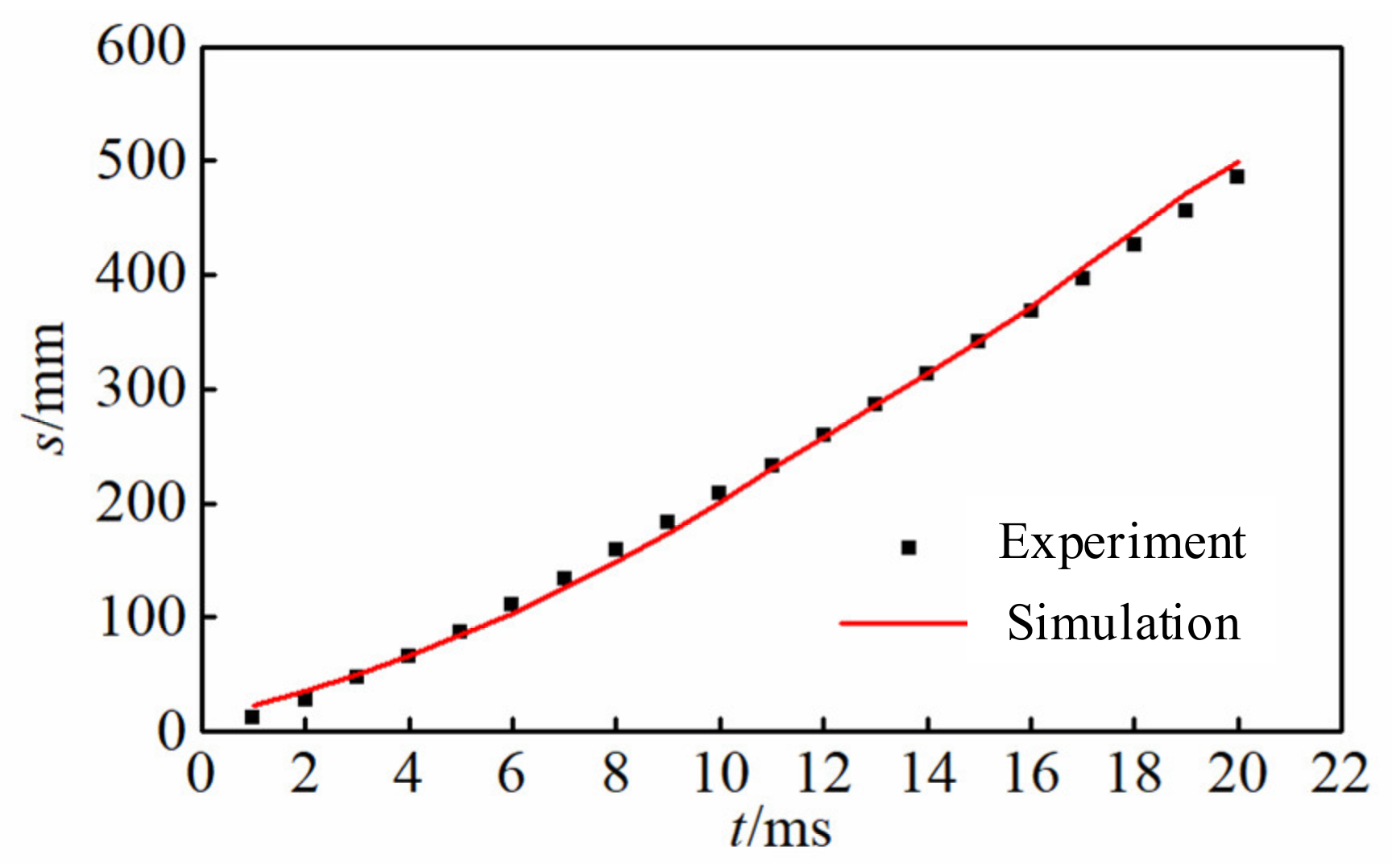
In the calculation, a dynamic mesh was used to deal with the grid motion. A three-dimensional unsteady solver was used, and the N-S equation was solved by the finite-volume method. Based on the above model and the numerical method, the experimental result of projectile E [18] was reproduced. Figure 1 and Figure 2 are the evolution sequence diagram and the axial displacement of gas-curtain for the numerical simulation and experiment, respectively. It can be found from Figure 1 and Figure 2 that the gas-curtain evolution process of the numerical result is basically consistent with the experiments, indicating that the above theoretical model is reasonable and feasible.

3. Analysis of Multiphase Flow Characteristics

3.1. Initial Condition

According to the new idea of the gas-curtain launch with a grooved launching tube, a calculation model was established as shown in Figure 3. The diameter and length of the launching tube was 30 mm and 1000 mm, respectively. The area of a single groove was 10 mm2 (groove width: groove height = 1). The diameter and length of the simulated projectile were both 30 mm.
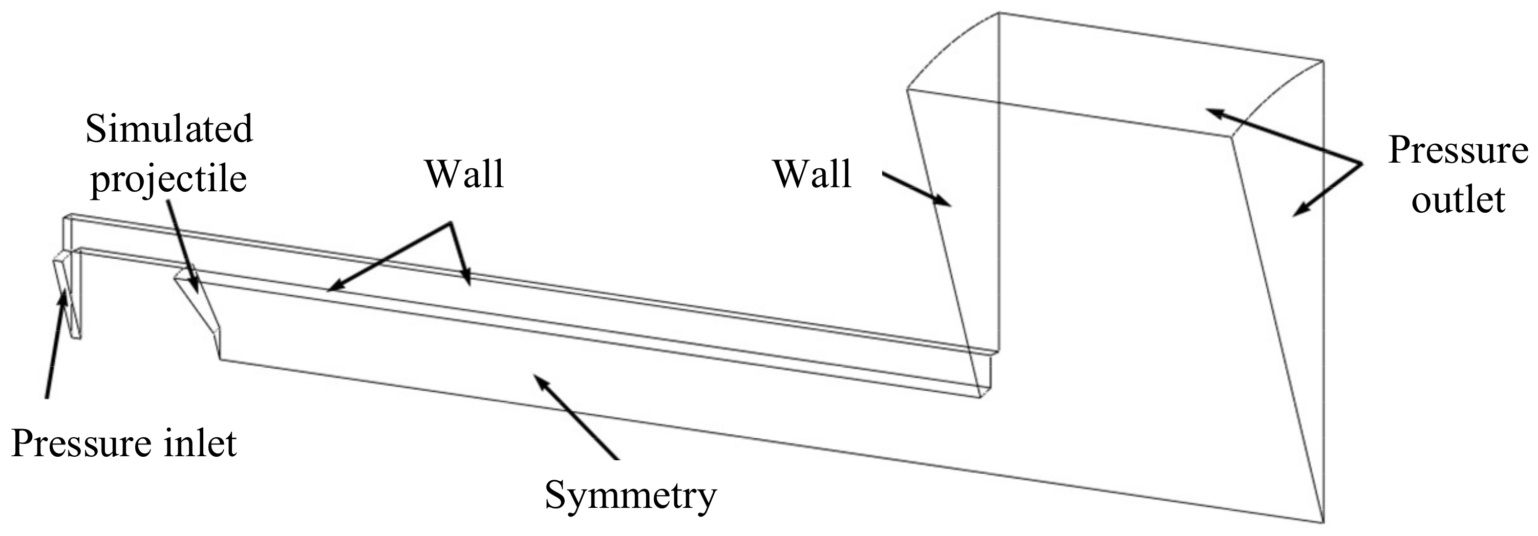
Take 1/16 of the whole model to establish the calculation domain, which is shown in Figure 4. For this, the pressure inlet is given by calculating the chamber pressure, the outlet pressure p = p0, and temperature T = T0. In the calculation process, the projectile is taken as a rigid body, and the velocity is calculated according to the projectile motion equation.

3.2. Numerical Analysis of Gas-Curtain Launching Process

Here, the loading parameters shown in Table 1 were used for the numerical simulation of the gas-curtain launching process. It should be noted that the coated 4/7 propellant was used in the calculation, and its coating burns slowly, which is mainly used to generate an effective gas-curtain to discharge the water in the launching tube. The propellant matrix burns fast to drive the projectile to move at high speed.
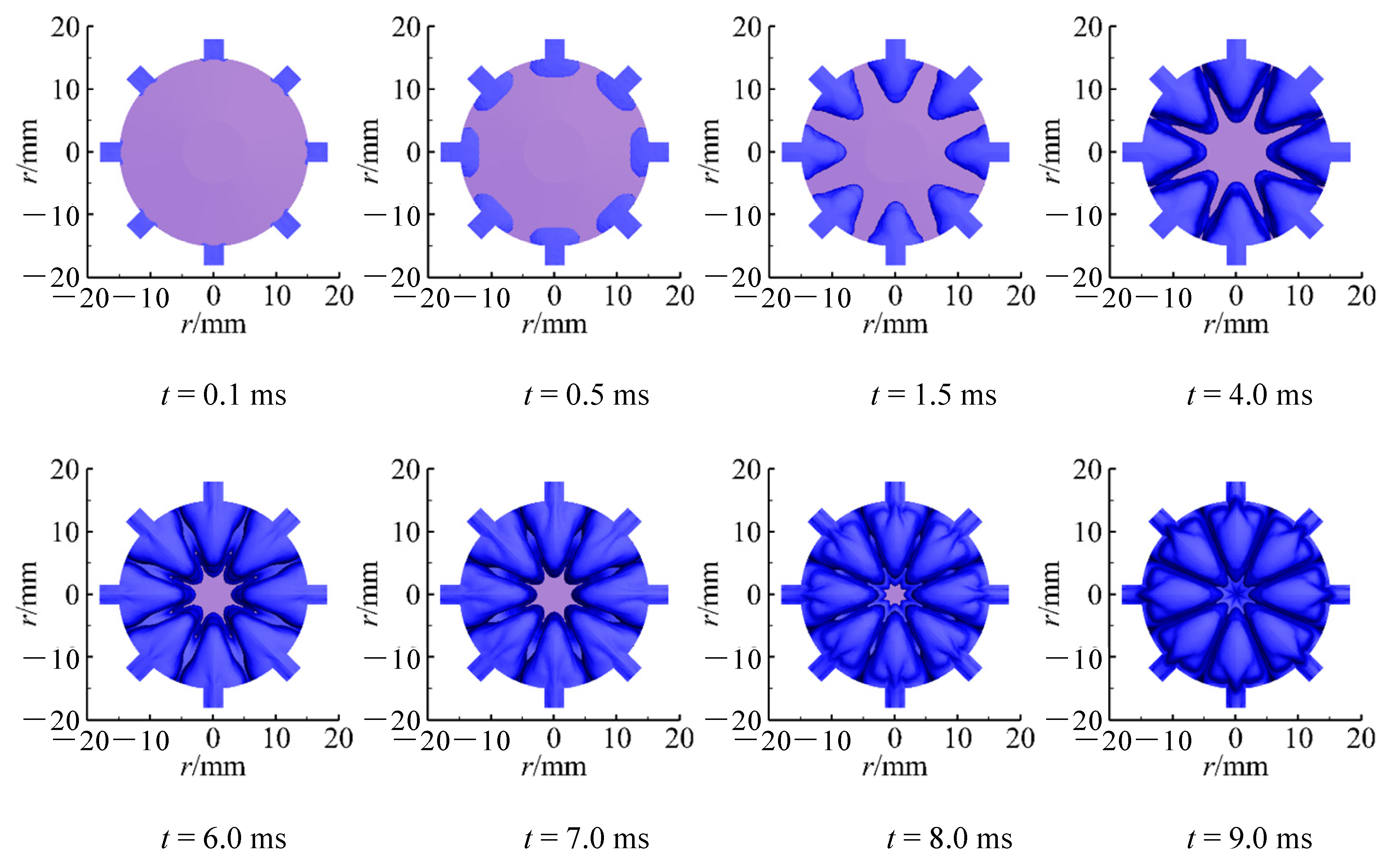
The top view of the spatiotemporal evolution process of the multi-groove jet is shown in Figure 5. The gas jet expands in the axial, circumferential, and radial directions, respectively, forming eight independent Taylor cavities. At 0.5 ms, the top view shape of the jet is rectangular. The adjacent groove jet begins to interact as it expands, which leads to the jet expansion weakening circumferentially and intensifying radially. At 1.5 ms, the jet gradually evolves from a rectangle to a triangle. At 4.0 ms, the jet is still triangular and adjacent jets begin to converge circumferentially, forming an annular gas channel in the launching tube. Subsequently, the gas jet continues to expand circumferentially and radially. At 9.0 ms, multi-groove jets converge radially, and then, a cylindrical gas channel is formed.
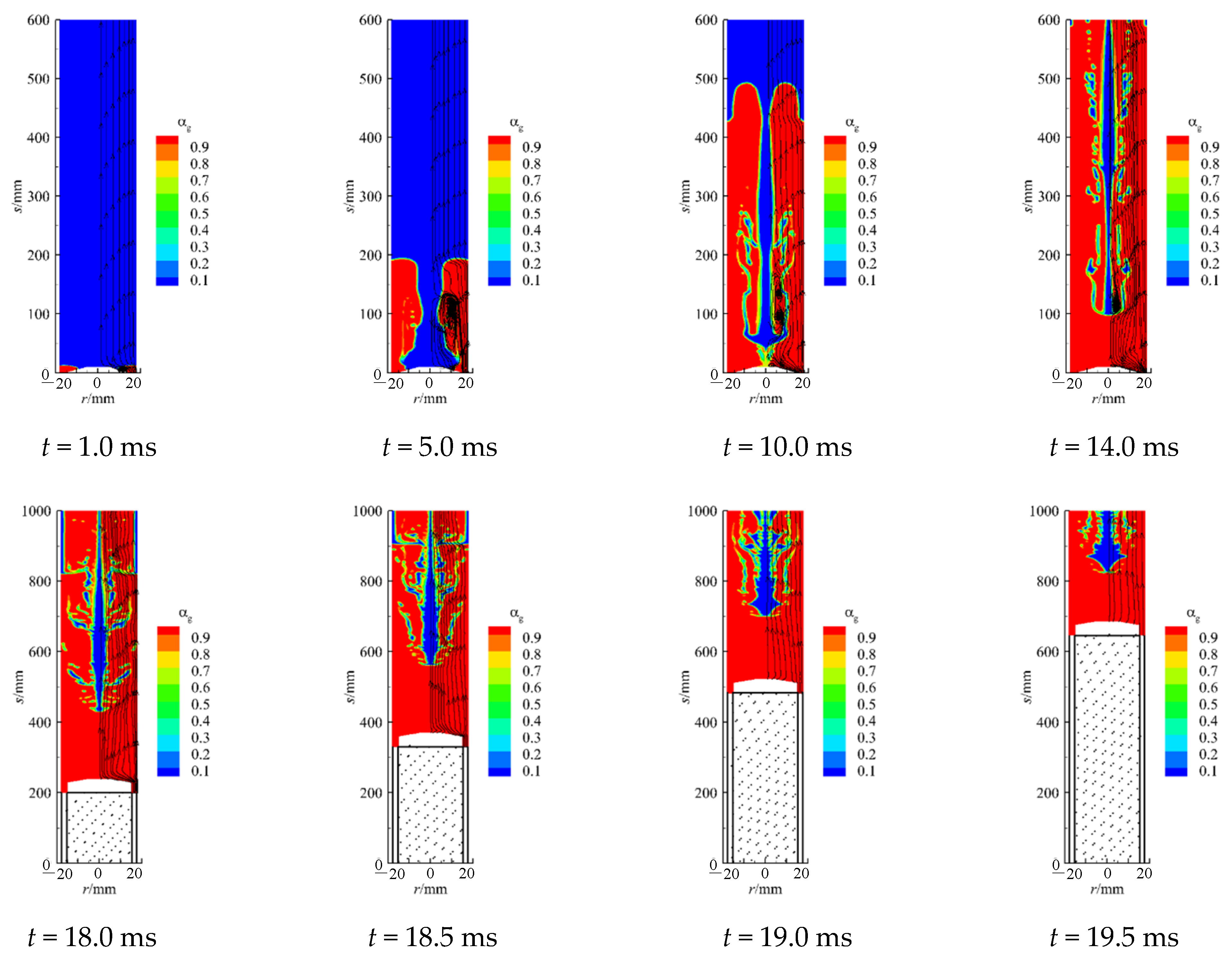
The phase distribution and vortex evolution diagram in the symmetrical section of the relative groove are given in Figure 6. At 1.0 ms, the streamline bends due to the retardation of water and the guidance of the projectile ramp. At this time, a vortex is generated near the projectile ramp in the Taylor cavity and the cavity contour is relatively regular. With the jet expanding, a few small droplets are drawn into the cavity at 5.0 ms. The turbulence effect makes the cavity surface wrinkled, and the scale of the vortex increases as well. Meanwhile, the vortex moves downstream, and the jet head moves closer to the central axis of the launching tube. At 10.0 ms, more droplets are involved in the Taylor cavity, and the wrinkles of the Taylor cavity contour are intensified, indicating that the Kelvin–Helmholtz instability is gradually enhanced. At s = 150 mm, two small vortices inside the Taylor cavity gradually approach, forming a large vortex. At the same time, a new small vortex is generated near the projectile head. With the continuous accumulation of the chamber gas, the chamber pressure keeps rising. The projectile in the tube begins to travel when the starting pressure is reached by the pressure differential between the projectile base and head. After the projectile moves, the small-scale vortex gradually disappear. It can be seen that the movement of the projectile has a restraining effect on the gas return in the Taylor cavity.
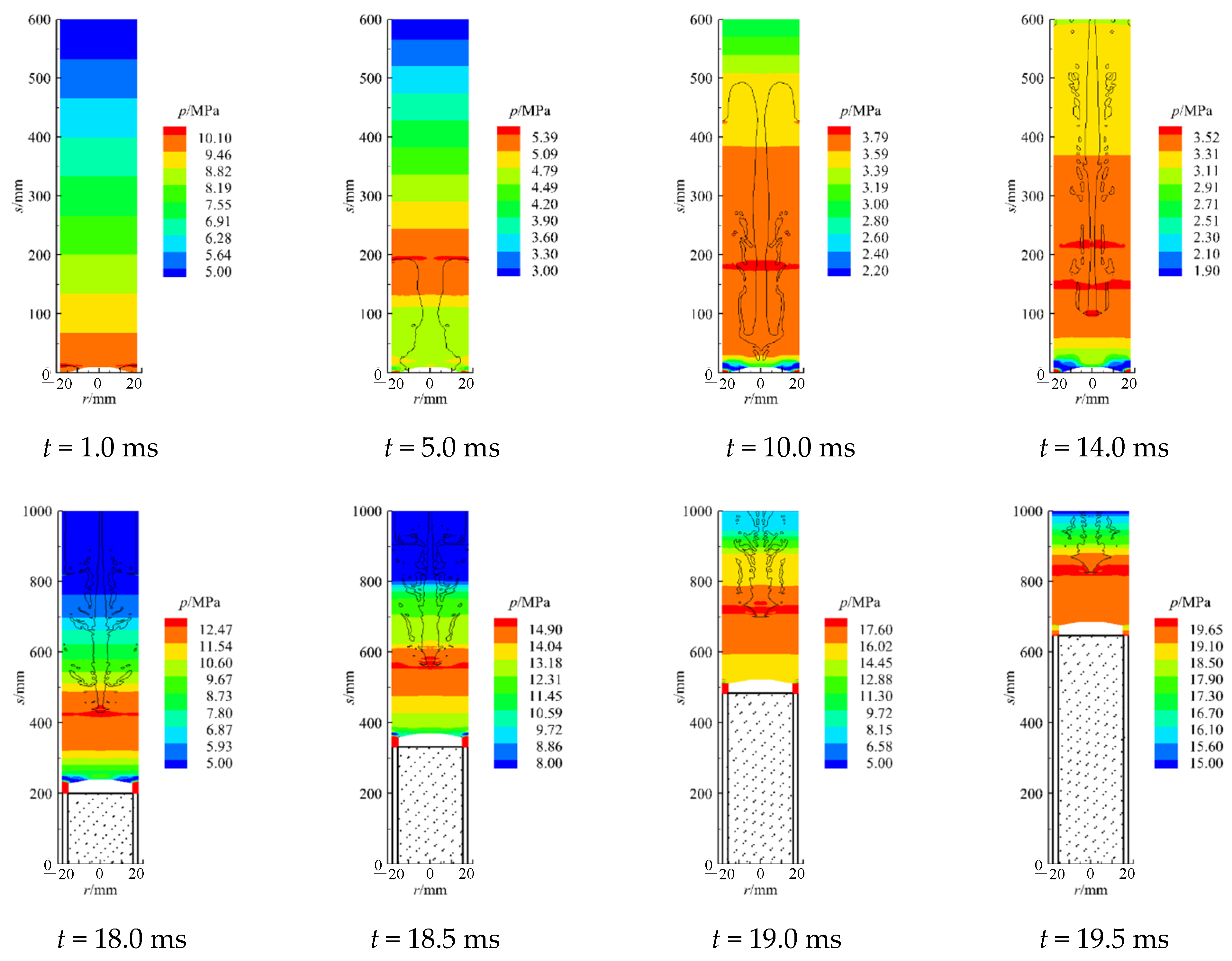
Figure 7 depicts the pressure distribution in the symmetrical section of the relative groove, and the jet profile is indicated by the black dotted line. It can be seen that the cavity expansion is more hindered by the water, and a localized high-pressure zone appears near the projectile head. At 5.0 ms, the maximum pressure decreases, and the localized high-pressure zone moves to s = 200 mm. At 10.0 ms, the pressure decreases further. At this time, a hump-shaped low-pressure zone appears at the projectile head, and the maximum pressure is located at s = 180 mm. At 14.0 ms, high-pressure areas appear at s = 150 mm and s = 210 mm, respectively. It is obvious that the high-pressure zone transfers from the jet head to the interior of the Taylor cavity with the jet extension, but the positions do not show obvious rules. From 18.0 ms to 19.5 ms, the interaction between the moving projectile and the gas-curtain gradually increases. On the one hand, the pressure gradually increases, as well as the distance between the high-pressure zone and the projectile head. On the other hand, the low-pressure zone near the projectile head changes from a hump to a layer shape, and its range gradually decreases.
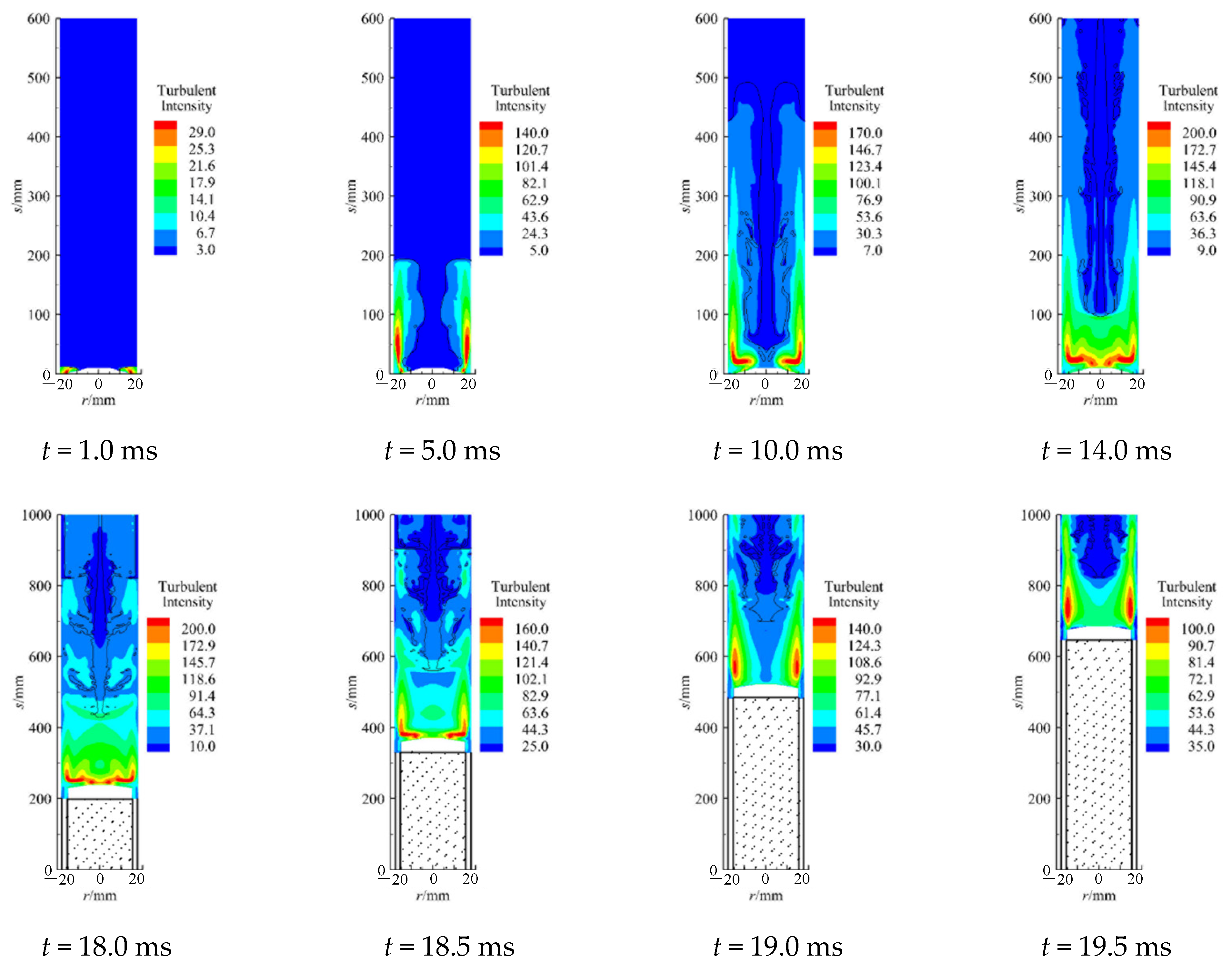
Figure 8 depicts the turbulence intensity distribution in the symmetrical section of the relative groove, and the jet profile is indicated by the black dotted line. From 1.0 ms to 14.0 ms, this is the gas-curtain expansion stage, in which the projectile has not yet moved. At this stage, the turbulence intensity in the tube gradually increases with the expansion of the jet, and the maximum turbulence intensity reaches 200 at 14.0 ms. During this period, the core area of the turbulence intensity is mainly located near the projectile head, and its shape gradually changes from a symmetrical strip (5.0 ms) to an oxhorn (14.0 ms). Thereafter, it is in the projectile motion stage (from 18.0 ms to 19.5 ms), and the turbulence intensity decreases with time. At 19.5 ms, the tube’s maximum turbulence intensity drops to 100. It is indicated that the projectile motion will inhibit the turbulence flow in the launching tube. At this stage, the core area of the turbulence intensity is still located in the front of the projectile, but its shape gradually degenerates from an oxhorn shape (18.0 ms) to a strip shape (19.5 ms). Besides, its position is mainly located directly above the projectile, that is 700 mm ≤ s ≤ 800 mm, r = 15.0 mm.
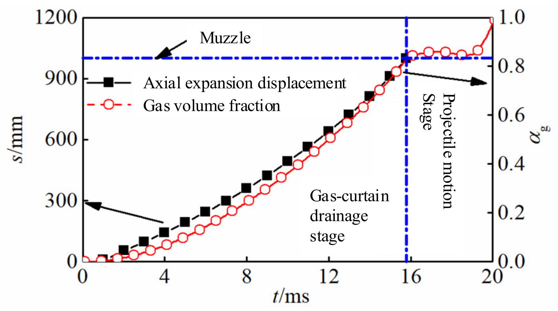
The axial displacement of the gas-curtain and the gas volume fraction are shown in Figure 9. In the gas-curtain drainage stage, with the gas-curtain’s continuous expansion, the axial displacement and the gas volume fraction both show nonlinear growth. At 15.8 ms, the gas-curtain develops near the tube exit and the gas volume fraction reaches 0.83. After the projectile starts moving, the gas volume fraction will first enter a plateau period, and then, it increases approximately linearly to 1.
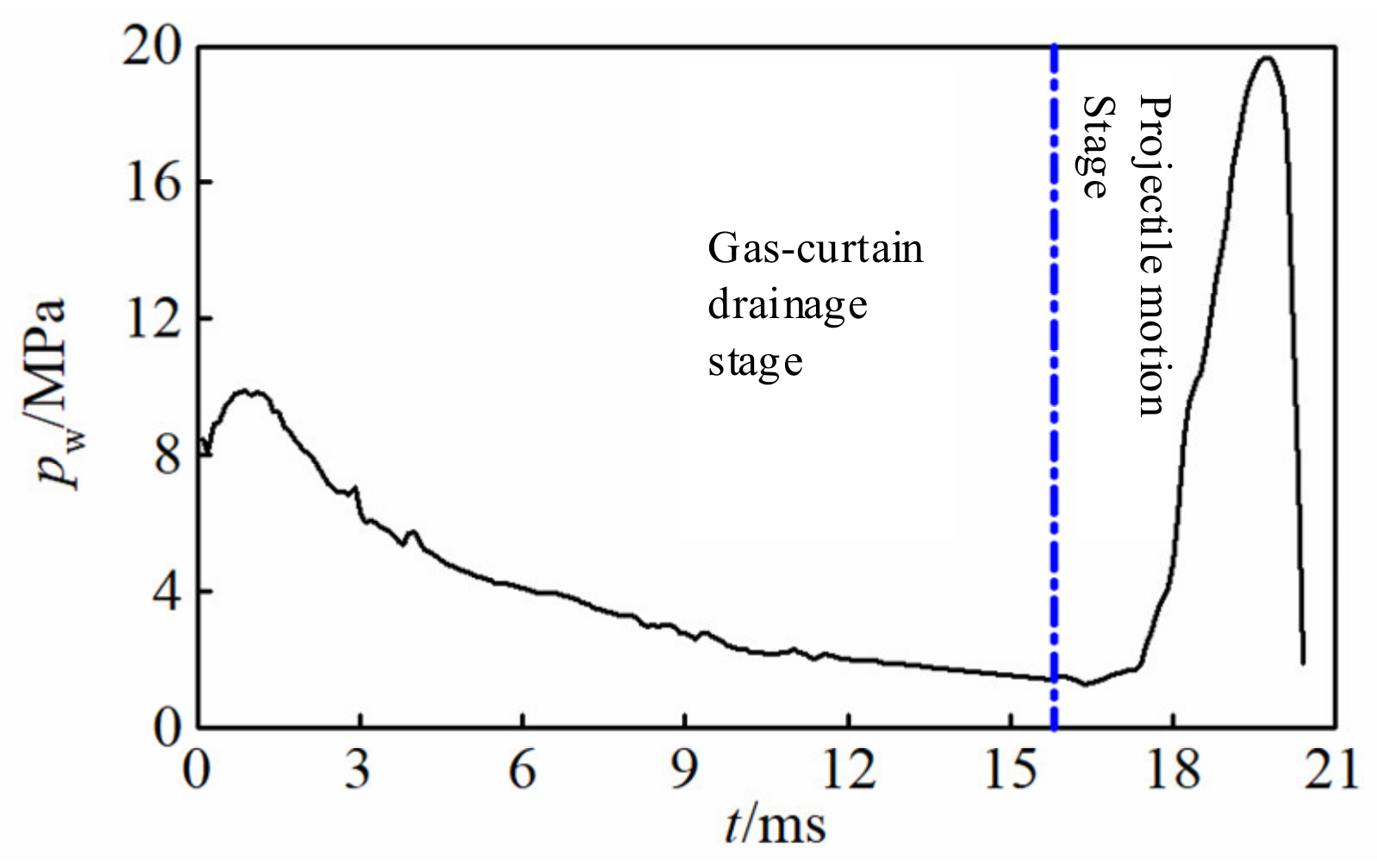
Figure 10 shows the pressure on the projectile head in the whole gas-curtain launching process. Before the projectile moves, the head pressure is mainly determined by the turbulence effect, so the pressure decreases with the jets’ extension and the discharge of water. Early in the projectile motion stage, the gas-curtain is only weakly squeezed by the low-velocity projectile. As a result, the pressure on the projectile head initially drops, but is ultimately still controlled by the turbulence effect. The interaction between the projectile and the gas-curtain steadily improves with increasing projectile velocity, which causes the head pressure to suddenly climb to a maximum pressure of 19.65 MPa.
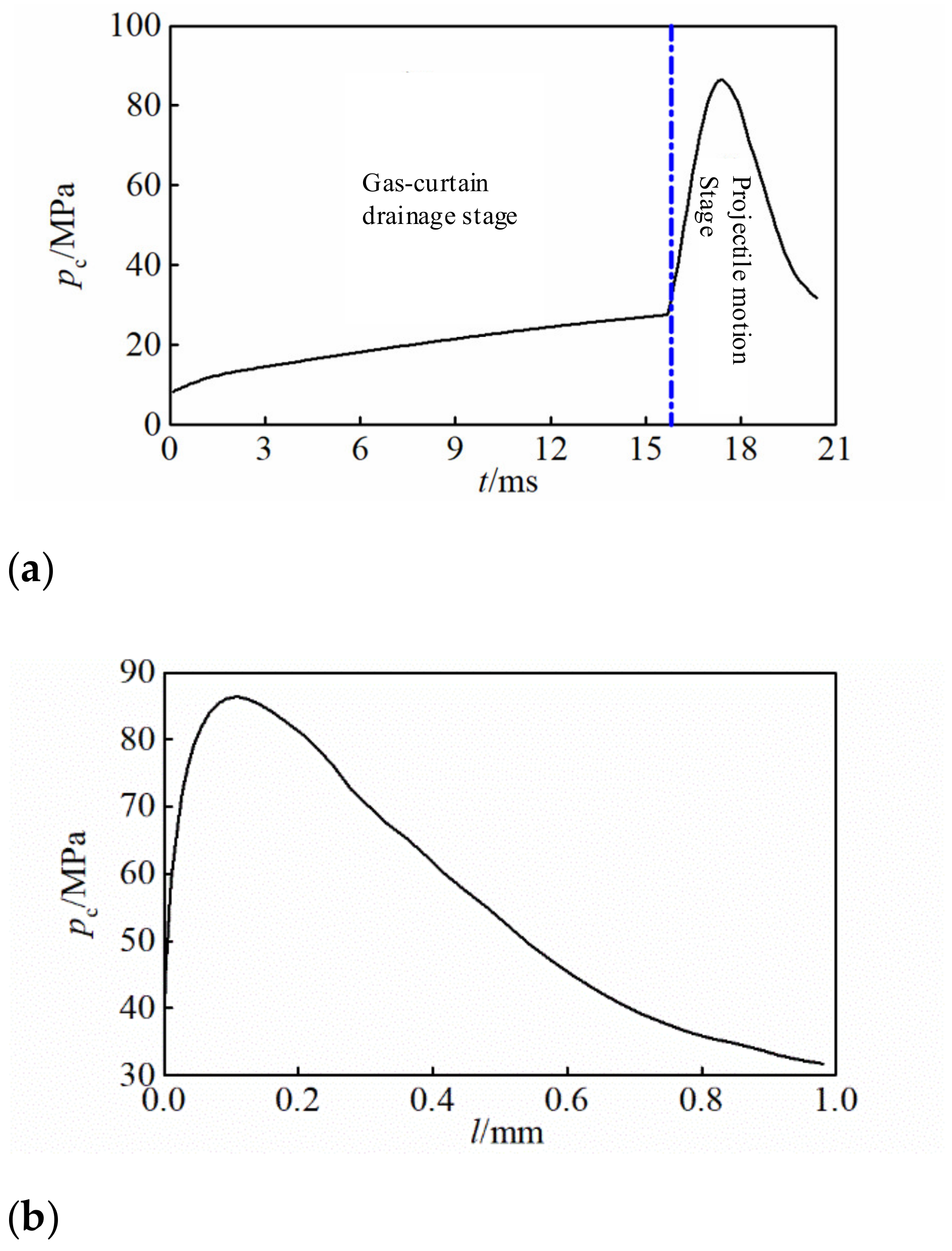
The curve of pressure against time in Figure 11a and the curve of pressure against projectile stroke in Figure 11b both depict the mean chamber pressure. In Figure 11a, the rising rate of pressure is slow in the gas-curtain drainage stage. On the one hand, this is because of the low burning rate of the propellant coating. On the other hand, some chamber gas is lost to generate the gas-curtain. At 15.7 ms, the coating is burned out. Then, the projectile starts moving and the propellant matrix starts burning. The high burning rate of the matrix makes the chamber pressure rise sharply and reach the maximum value of 86.34 MPa at 17.4 ms. After that, due to the rapid increase of the projectile velocity, the chamber pressure drops quickly.
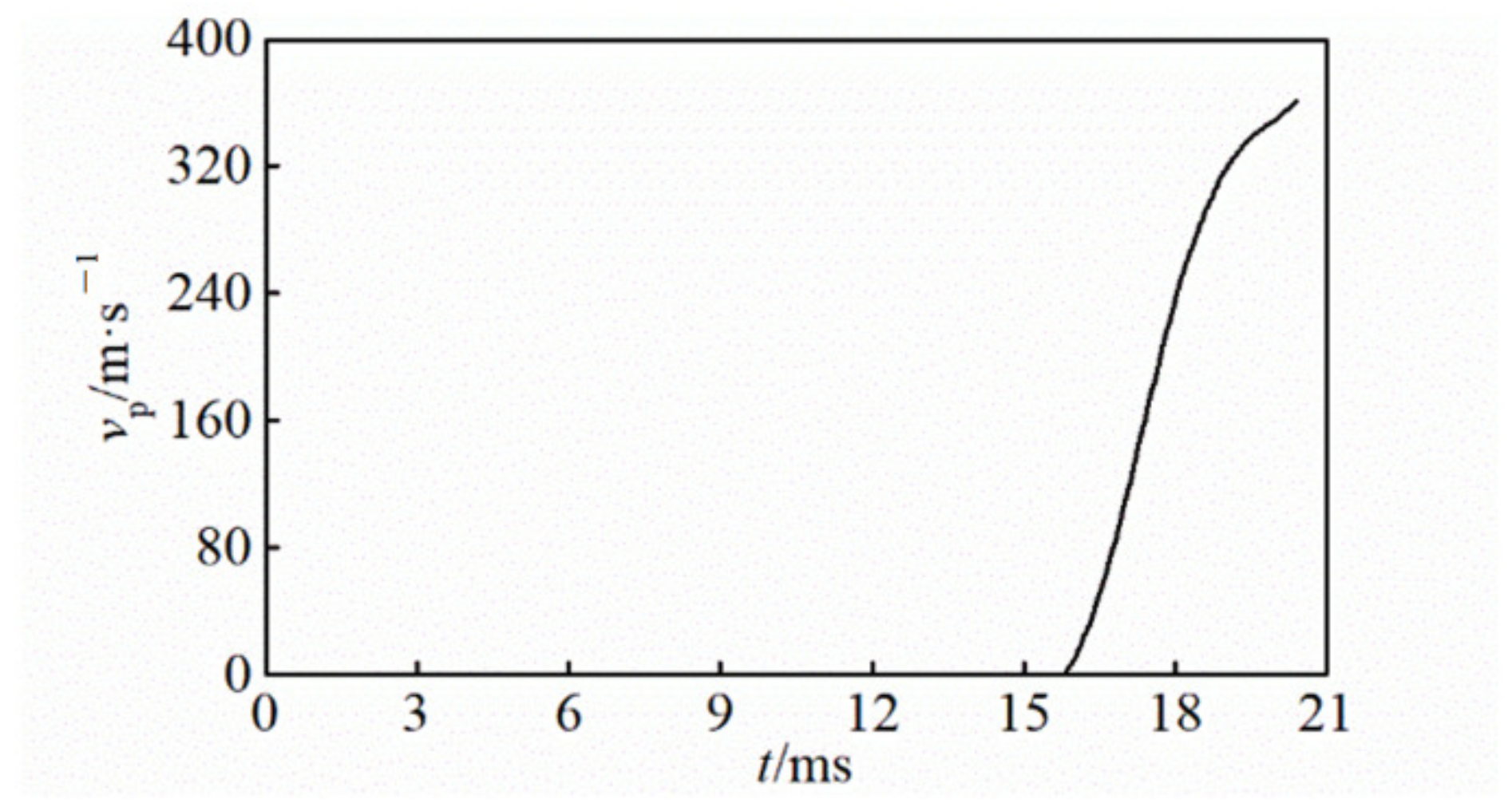
The projectile velocity curve in the gas-curtain launching process is shown in Figure 12. In the gas-curtain drainage stage, the pressure difference before and after the projectile has not reached the projectile starting pressure, so the projectile is in a static state. With the continuous increase of the chamber pressure, the projectile starts to move at 15.8 ms, and its speed increases rapidly, reaching 360.58 m/s when the projectile moves out of the muzzle.

4. Conclusions

This study presented a detailed analysis of the evolution characteristics of the gas–liquid interaction in a new gas-curtain launcher.
First of all, the theoretical model for the new launcher was established and verified by numerical simulation. Meanwhile, the evolution characteristics of the gas-curtain flow field were investigated in detail by analyzing the phase, pressure, and turbulence intensity distribution. The morphological changes of the groove jets and the gas-curtain extension show that the newly proposed gas-curtain launcher can effectively drain the pre-projectile water. It almost exhausted the 1 m-long water column in 15.8 ms, and finally, the gas volume fraction before the projectile starts reached 83%. Besides, this new gas-curtain launcher can effectively reduce the launching resistance, and the maximum pressure on the projectile head is 19.65 MPa in the whole launching process. The calculated conditions in this paper resulted in an initial velocity of 360.58 m/s at a maximum chamber pressure of 86.34 MPa.
In the future research, it is suggested that the matching design of the charge and groove should be carried out to reveal the key factors affecting the effectiveness of gas-curtain drag reduction and its influencing mechanism.

Author Contributions

Conceptualization, X.Z. and Y.Y.; methodology, X.Z. and Y.Y.; formal analysis, X.Z. and Y.H.; investigation, X.Z. and Y.H.; resources, X.Z. and Y.Y.; data curation, X.Z.; writing—original draft preparation, X.Z.; writing—review and editing, Y.Y.; supervision, X.Z.; project administration, X.Z.; funding acquisition, X.Z. All authors have read and agreed to the published version of the manuscript.

Funding

This research was funded by the National Key Laboratory Fund (Grant Number 6142604200309) and the China Postdoctoral Science Foundation (Grant Number 2020M681596).

Institutional Review Board Statement

Not applicable.

Informed Consent Statement

Not applicable.

Data Availability Statement

The data in this article are true and valid. The data presented in this study are available in this article and (https://doi.org/10.3390/jmse10091239).

Conflicts of Interest

The authors declare no conflict of interest. The funders had no role in the design of the study; in the collection, analyses, or interpretation of the data; in the writing of the manuscript; nor in the decision to publish the results.

References

  1. Fan, C.; Li, Z.; Du, M.; Yu, R. Numerical study on the influence of vehicle diameter reduction and diameter expansion on supercavitation. Appl. Ocean. Res. 2021, 116, 102870. [Google Scholar] [CrossRef]
  2. Yoon, K.; Li, J.; Shao, S.; Karn, A.; Hong, J. Investigation of ventilation demand variation in unsteady supercavitation. Exp. Therm. Fluid Sci. 2021, 129, 110472. [Google Scholar] [CrossRef]
  3. Wang, Y.; Huang, C.; Du, T.; Huang, R.; Zhi, Y.; Wang, Y.; Xiao, Z.; Bian, Z. Research on ventilation and supercavitation mechanism of high-speed surface-piercing hydrofoil. Phys. Fluids 2022, 34, 023316. [Google Scholar] [CrossRef]
  4. Liu, Y.P.; Li, J.X.; Yang, Z.; Bo, Y.C. Interior ballistics analysis and numerical simulation of underwater gun. J. Gun Launch Control. 2007, 28, 30–33. [Google Scholar]
  5. Liu, H.; Peng, X.; Zou, Z. Effects of the launch speed on hydrodynamic force of the underwater vehicle vertical launch with the gas-curtain. Adv. Mater. Res. 2012, 625, 84–87. [Google Scholar] [CrossRef]
  6. Hu, Z.; Yu, Y. Expansion characteristics of multiple wall jets in cylindrical observation chamber. Appl. Therm. Eng. 2017, 113, 1396–1409. [Google Scholar] [CrossRef]
  7. Weiland, C.; Vlachos, P.; Yagla, J. Concept Analysis and Laboratory Observations on a Water Piercing Missile Launcher. Ocean. Eng. 2010, 37, 959–965. [Google Scholar] [CrossRef]
  8. Cao, W.; Liu, H.; Wang, C. The effect of gas jet speed on the motion process of the underwater vehicle vertical launching by using gas-curtain. Eng. Mech. 2013, 30, 288–292. [Google Scholar]
  9. Qiu, H.; Yuan, X.; Wang, Y.; Liu, C.L. Research on the law of development of outlet cavity during the launch of submarine launched missile. Acta Armamentarii 2014, 35, 1510–1514. [Google Scholar]
  10. Zhang, W.; Jia, G.; Wu, P.; Yang, S.; Huang, B.; Wu, D. Study on hydrodynamic characteristics of AUV launch process from a launch tube. Ocean. Eng. 2021, 232, 109171. [Google Scholar] [CrossRef]
  11. Chen, J.; Wang, C.; Di, C.; Liu, G. Interior Ballistic Calculations of an Under Water Gun at Various Depths. Acta Armamentarii 2002, 23, 462–464. [Google Scholar]
  12. Fu, J.H.; Howard, R.J.; Rapp, J.W.; Paulic, A. Underwater Gun Comprising a Plate-Type Barrel Seal. U.S. Patent No. 7,874,091, 25 January 2011. [Google Scholar]
  13. Sun, P.; Xie, Z.; Yang, Z.; Lan, W. Analysis of the influence of the inlet of the barrel on the shooting. J. Ordnance Equip. Eng. 2018, 39, 68–72. [Google Scholar]
  14. Zhou, L.; Yu, Y. Study on Interaction Characteristics between Multi Gas Jets and Water During the Underwater Launching Process. Exp. Therm. Fluid Sci. 2017, 83, 200–206. [Google Scholar] [CrossRef] [Green Version]
  15. Zhou, L.; Yu, Y. Experimental study on gas-curtain generation characteristics by multicombustion-gas jets in the cylindrical liquid chamber. Ocean. Eng. 2015, 109, 410–417. [Google Scholar] [CrossRef]
  16. Zhao, J.; Yu, Y. The Interaction between Multiple High Pressure Combustion Gas Jets and Water in a Water-Filled Vessel. Appl. Ocean. Res. 2016, 61, 175–182. [Google Scholar] [CrossRef]
  17. Zhang, X.; Yu, Y.; Zhou, L. Numerical study on the multiphase flow characteristics of gas-curtain launch for underwater gun. Int. J. Heat Mass Transf. 2019, 134, 250–261. [Google Scholar] [CrossRef]
  18. Zhang, X.; Yu, Y.; Hu, Y. Experimental Study on Gas–Liquid–Solid Interaction Characteristics in the Launch Tube. J. Mar. Sci. Eng. 2022, 10, 1239. [Google Scholar] [CrossRef]
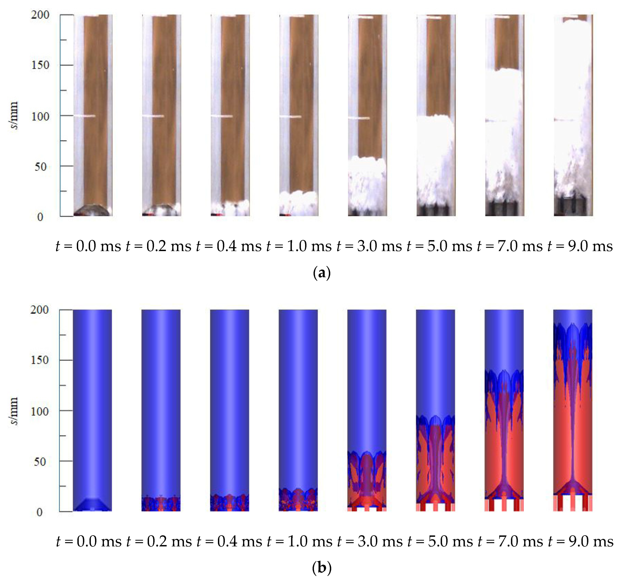
Figure 1. Sequence diagram of gas-curtain formation and expansion. (a) Experimental results. (b) Simulation.
Jmse 11 00055 g001
Figure 2. Axial extension displacement of the gas-curtain.
Jmse 11 00055 g002
Figure 3. Schematic diagram of calculation model. (a) Launching tube. (b) Cross-section of launching tube. (c) Simulated projectile.
Jmse 11 00055 g003
Figure 4. Schematic diagram of calculation domain.
Jmse 11 00055 g004
Figure 5. Top view of gas-curtain launching process.
Jmse 11 00055 g005
Figure 6. The phase distribution and vortex evolution diagram in symmetrical section of the relative groove.
Jmse 11 00055 g006
Figure 7. Pressure distribution in symmetrical section of the relative groove.
Jmse 11 00055 g007
Figure 8. Turbulence intensity distribution in symmetrical section of the relative groove.
Jmse 11 00055 g008
Figure 9. The gas-curtain axial displacement and the gas volume fraction in the tube.
Jmse 11 00055 g009
Figure 10. Projectile head pressure.
Jmse 11 00055 g010
Figure 11. The mean chamber pressure. (a) p-t; (b) p-l.
Jmse 11 00055 g011
Figure 12. Projectile velocity.
Jmse 11 00055 g012
Table 1. Loading parameters of the interior ballistics.
ParameterValueUnitParameterValueUnit
hb0.125mm ω p 0.09kg
u b 1.81 × 10⁻⁸m/(s·Pan) u p 1.82 × 10⁻⁸m/(s·Pan)
n b 0.77/ n p 0.86/
f b 7.5 × 10⁵kJ/kg f p 9.5 × 10⁵kJ/kg
ρ b 1650kg/m3 ρ p 1650kg/m3
V 0 1.94 × 10⁻⁴m3m0.29kg
P08.0MPaPj30.0MPa
Disclaimer/Publisher’s Note: The statements, opinions and data contained in all publications are solely those of the individual author(s) and contributor(s) and not of MDPI and/or the editor(s). MDPI and/or the editor(s) disclaim responsibility for any injury to people or property resulting from any ideas, methods, instructions or products referred to in the content.