Article

Modeling and Analysis of Offshore Gangway under Dynamic Load

1
Marine Engineering College, Dalian Maritime University, Dalian 116026, China
2
National Center for International Research of Subsea Engineering Technology and Equipment, Dalian Maritime University, Dalian 116026, China
*
Author to whom correspondence should be addressed.
J. Mar. Sci. Eng. 2023, 11(1), 77; https://doi.org/10.3390/jmse11010077
Submission received: 27 November 2022 / Revised: 16 December 2022 / Accepted: 28 December 2022 / Published: 3 January 2023
(This article belongs to the Section Ocean Engineering)

Abstract

:
The safety transfer on the sea is threatened by wind, wave and surge loads. An offshore gangway ensures smooth and safe transfer by compensating the ship’s motion. In a mixed offshore gangway system, the transfer gangway is a huge asymmetric load on top of the stable platform, and the displacement of its center of gravity causes it to exert a large dynamic load on the stable platform. A dynamic model of the offshore gangway under dynamic load is established in this work. The Lagrange equation is used to establish the dynamic model of the transfer gangway; the equivalent center of gravity method is used to visualize its dynamic load. The dynamic of the stable platform is modeled by the virtual work principle. Finally, the accuracy of the mathematical model was verified by the joint simulation. Simulation results indicate that under the influence of dynamic load, the tractive force of the second drive support chain is 2–3 times greater than the tractive force of the first and third drive support chains. With the same excitation, the tractive force of the second drive support chain is 2.83 times higher than that under the static load.

1. Introduction

Offshore wind energy is recognized as an important vehicle to achieve energy transition and carbon neutrality, and its development potential is huge [1,2]. The construction, commissioning, testing and maintenance of offshore wind turbines require the participation of personnel, while offshore transfer operations are vulnerable to safety accidents caused by the threat of heavy waves, storms and fog. With the rapid growth in the number of offshore wind farms worldwide, equipment for the safe transfer of people and cargo on the sea has seen increased demand. To ensure stable, safe, and effective maritime transshipment, offshore gangways can counteract the ship’s multi-dimensional swing motions and keep the transfer object steady in the inertial space [3,4]. The offshore gangway has attracted extensive research by related scholars. Liang et al. [4] used the Euler–Lagrange equations to model the kinematics and dynamics of a serial transfer gangway, respectively. Additionally, they designed an improved dynamic controller to simulate the gangway end moving along the desired trajectory and the docking case, respectively. Dong et al. [5] studied the coupling dynamics and gangway response of a turret mooring floating production, storage and unloading (FPSO) device and a semi-submersible regulation platform (AP) using numerical methods. Based on the potential theory, the hydrodynamic forces considering multi-body wave interactions were calculated in the frequency domain, and the limiting response of the channel was predicted based on the Weibull distribution, whereby the environmental criterion was determined. Li et al. [6] analyzed the hydrodynamic interaction of a multi-body system, studied the extension, contraction, rotation and relative motion motions during serial transfer gangway operation and calibrated and verified the nonlinear transverse rocking damping in free decaying waves and regular waves.
This work establishes the dynamic model of the series-parallel mixed offshore gangway, which accounts for the dynamic load placed by the transfer gangway on the stable platform.
Dynamics describes the relationship between joint moments, kinetic parameters and joint motion, and these relationships can help achieve subsequent high-speed, high-precision motion control. The parallel structure in the mixed mechanism of this paper is a nonlinear system with a complex structure, multiple variables, multiple degrees of freedom and multiple parameters coupling, and the dynamics model established needs to match the actual dynamic characteristics of the mechanism if the desired control effect is to be achieved. Early studies of dynamics mainly included Newton–Euler equations and Lagrange equations, which belong to the category of classical mechanics and are friendly for modeling the dynamics of simple rigid body systems with fewer degrees of freedom. Newton–Euler equations belong to the category of vector mechanics, which solve dynamic problems by combining force balance equations, while Lagrange dynamics are based on the conservation of work and energy [7]. Liu et al. [8] derived the dynamic model of the simplified structure of the three-RRC parallel manipulator using Lagrange equations. A six-DOF stable platform’s Newton–Euler dynamic model was modeled by Wang et al. and validated by simulations [9]. Based on a modified formulation of the Lagrange equation, Muralidharan et al. provided a method for calculating the inverse dynamics [10]. Chen et al. [1] integrated the effects of inertial forces, elastic forces, damping forces and combined bending and torsion moments, and established the dynamics model of the soft manipulator through the modified Newton–Euler iterative equation. The principle of virtual work circumvents the constraint and constraint couple forces inside the mechanical systems, and it is very friendly for analyzing strongly coupled systems [11]. Javad et al. [12] proposed a dynamic modeling method based on the principle of virtual work and the linked Jacobian matrices, which eliminates the constraint and moments at the passive joints, and the dynamic model of the parallel manipulator is simplified to a system of three linear equations with three unknowns. Yang et al. [13] derived the explicit and linearized dynamics equations for the Stewart platform with high accuracy and simplicity using the principle of virtual work. Alaleh et al. [14] modeled the dynamics of a four-DOF over-constrained parallel manipulator by the principle of virtual work. Kane equations and generalized momentum equations are effective new methods used to establish the dynamical equations of complex multi-rigid body systems [15]. Cheng et al. [16] derived the kinetic formulation of the hip joint with a 3SPS+1PS space-parallel manipulator as the core module using the Kane equation, and it obtained the relationship between the velocity and acceleration of the motion platform and the drive support chains. A dynamic model using the Kane equation was created by Yang et al. for a parallel platform [17]. The generalized momentum equation, which requires less computing than the conventional Lagrange equation, was used by Lopes to study a dynamics of parallel systems [18]. Xin proposed a systematic approach to model the inverse dynamics of a three-DOF complex non-redundant manipulator by combining the Lagrange equation and the principle of virtual work [19]. Dynamic methods can also be combined to analyze a complex system. Mirjana [20] successfully modeled the dynamics of a complex cable-suspended parallel robot using a Lagrange equation low-range model based on the principle of virtual work. Tian et al. [21] constructed closure dynamics of the broad range of parallel systems by integrating the concepts of D’Alembert and virtual principle. Liu [22] solved the joint output forces of highly redundant parallel manipulators under non-redundancy and full-redundancy driving modes using the principle of virtual work, and proposed a load distribution algorithm based on Lagrange optimization for full-redundancy driving, which avoids the joint overload caused by the traditional minimum constant load distribution scheme and improves the positioning accuracy of the manipulator.
In this paper, a dynamic model of the offshore gangway’s 3UPU/UP-RRP series-parallel mixed structure is constructed using Matlab. The exactitude of the model is confirmed via joint simulation. The dynamics of the people transfer operation are examined based on the model presented. The impact of the dynamic load placed by the transfer gangway on the tractive force of the stable platform’s drive support chains is examined, and the viability of the ship motion compensation scheme—in which the stable platform corrects for roll and pitch motions of the ship and the transfer gangway corrects the transfer destination’s three-dimensional displacement with respect to the ship—is confirmed.
More specifically, the following areas are those in which the paper makes contributions and introduces innovative ideas:
(1)
A dynamic model of the mixed offshore gangway under dynamic load is comprehensively established. The model is also applicable to the dynamic analysis of the personnel transfer operation process. The exactitude of the model is confirmed by joint simulation. To the best of the authors’ knowledge, the dynamic model of the offshore gangway under dynamic load is established first time in this paper.
(2)
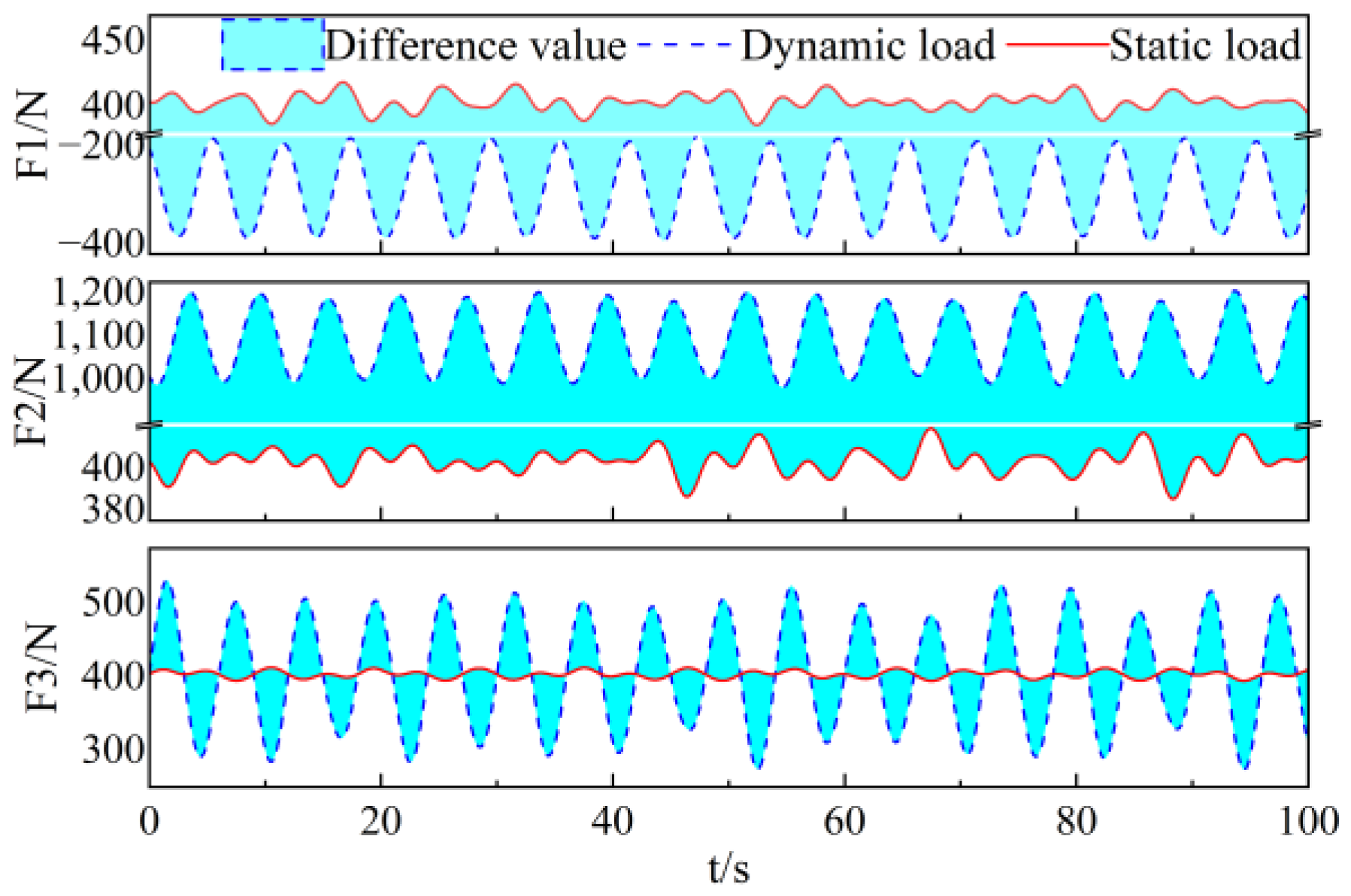
The analysis of the dynamic model results show that the dynamic load applied to the stable platform by the transfer gangway has a significant effect on the tractive force of the stable platform’s drive support chains. The tractive force of the first drive support chain of the stable platform changes from positive to negative when the personnel transfer operation is carried out, which is worthy of follow-up study and has certain guiding significance for the practical application of the mixed structure offshore gangway.
(3)
Compared with no ship motion compensation, the ship motion compensation scheme can compensate for 83% of the ship motion in this paper.
The rest of the paper is presented below. The mixed offshore gangway construction is introduced in Section 2, along with its frame. The dynamic is modeled in Section 3. This includes calculating the tractive force of each joint in the transfer gangway, the dynamic load, the platform posture, the velocity and acceleration of the drive support chains, the force of each component of the stable platform, etc., before establishing the general dynamic model. Section 4 compares the traction forces in the drive support chains for stable platforms with and without dynamic loads, analyzes the dynamics of the system during the execution of personnel transfer operations using the model and then analyzes the response of the end point position of the gangway with and without compensation control. This paper’s conclusions are presented in Section 5.

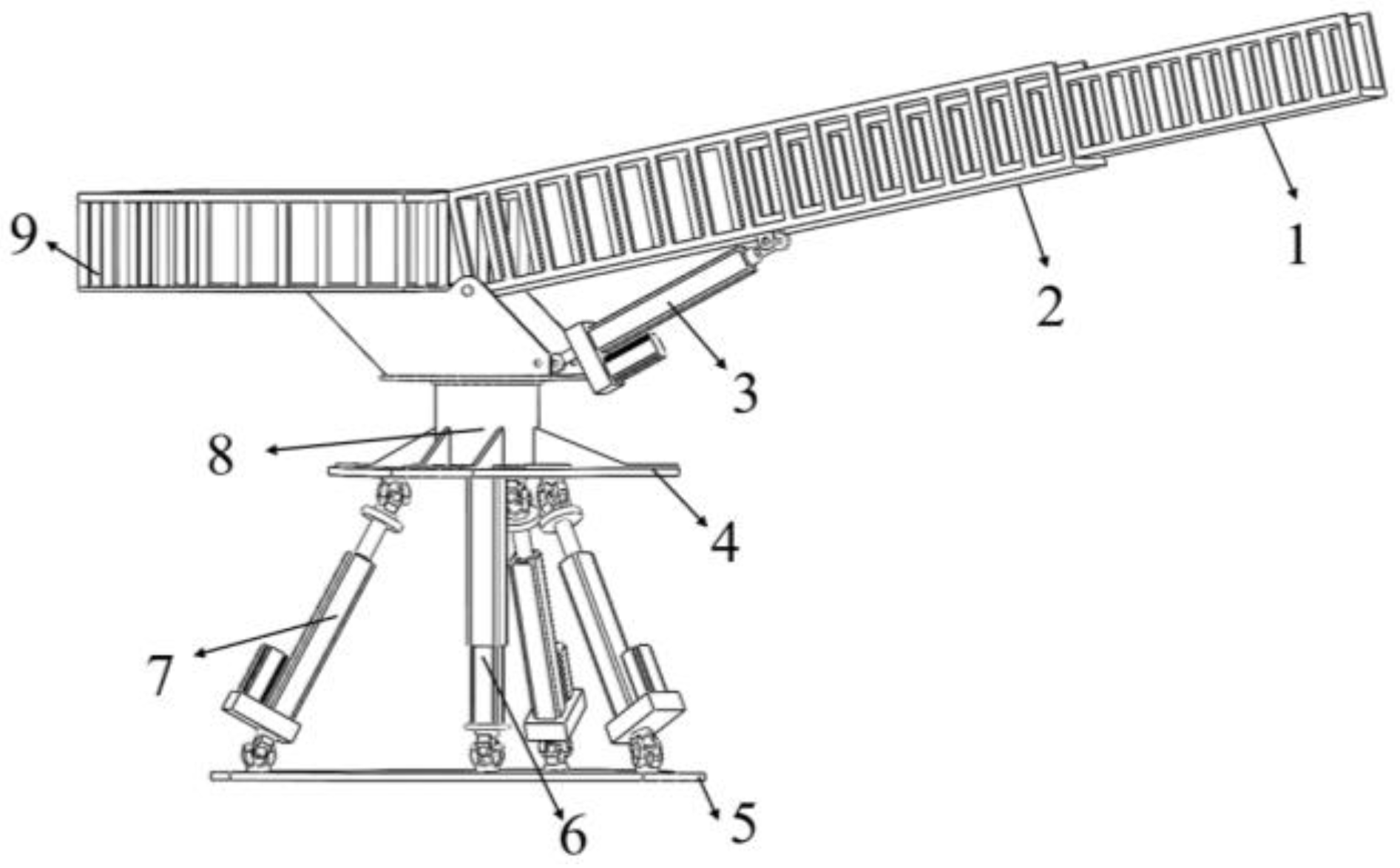
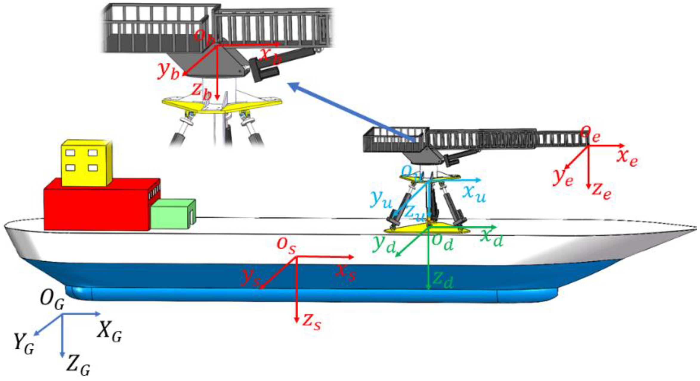
2. Structure and Spatial Framework of the Overall System

2.1. Introduction of the Organization

In Figure 1, a stable platform and a transfer gangway that is fixedly coupled to the fixed platform of the stable platform make up the mixed offshore gangway. A moving platform, a fixed platform, three UPU structure drive support chains and a UP structure follower branch chain make up the stable platform in this paper, which is described as a 3UPU/UP structure (U stands for Hooke’s joint and P for the actuator’s sliding pair). The follow-on support chain joins the centers for the moving platforms, which are parallel to one another. The top and moving platforms are connected by the drive support chains, which symmetrically encircle the follow-on support chain. Due to the stable platform’s limited ability to move in the vertical direction, the structure determines that it has one degree of movement and two degrees of freedom of rotation. As a result, it primarily uses these rotational DOFs to account for the ship’s roll and pitch motions, keeping the fixed platform horizontal and enhancing the smoothness of the system (transfer gangway) on top of the fixed platform during sea transfer [23]. A transfer platform, a pitching motor, a main arm, a telescopic arm, and a telescoping motor make up the RRP series gangway. A certain amount of mobility is produced by the telescoping motor, which joins the telescopic arm to the main arm. The main arm is joined to the transfer platform by the pitching motor, which allows for some rotational freedom. The slewing mechanism connects the transfer platform to the fixed platform of the stable platform, providing rotational freedom. The transfer gangway is employed to account for the transfer destination’s three-dimensional displacement with respect to the ship due to the vast working space of the serial mechanism [24]. The stable platform and transfer gangway arrangement ensure the security of the marine transfer.

2.2. Geometrical Modeling

In Figure 2, o G is a reference frame. o s is a fixed frame of the hull. o d is the moving platform fixed frame, o d is located at the mass center of the moving platform and each axis is oriented in a direction as the hull frame. o u is the fixed platform reference frame, with the center of the fixed platform as the origin, and the z u -axis is always vertically downward. o b is the pitch arm frame, and o b is located at the mass center of the pitch axis, where the z b -axis is always vertical down, while the x b -axis is in a direction as the main arm. o e is the telescopic arm frame, o e is located at the center of the end of the main arm and each axis is oriented in the same direction as o b .

3. Dynamic Model

The study of dynamics is of great significance to structural optimization and control methods. The study of dynamics mainly includes several aspects such as force analysis of the mechanism, the establishment of a dynamics model, computer simulation and identification of dynamic parameters, among which the establishment of a dynamics model is an extremely important aspect [25].

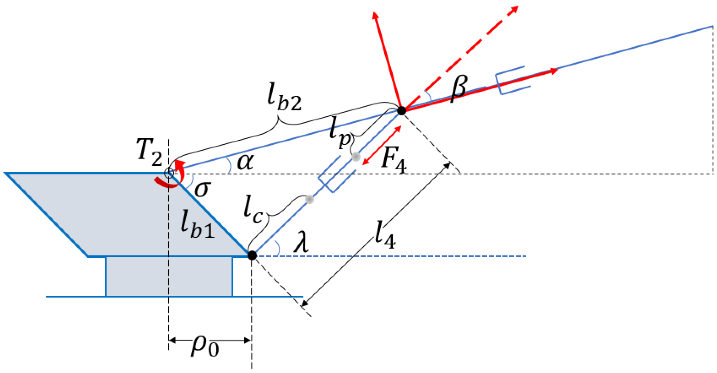
3.1. Dynamic Model of RRP Transfer Gangway

The transfer gangway, which frame is depicted in Figure 3 and Figure 4, is utilized to account for the transfer destination’s three-dimensional displacement with respect to the ship. Section 2.2 provides an explanation of this frame.

3.1.1. Analysis of Kinetic and Potential Energy of the Slewing Mechanism

The mass of the slewing mechanism is concentrated to be uniform, then its barycenter is located on the geometric center of the slewing mechanism, and the barycenter of the slewing mechanism can be expressed in the fixed platform frame o u x u y u z u as:
P m b = 0 0 l m b
where l m b is the distance from the barycenter of the slewing mechanism to the fixed platform.
Since the movement of the slewing mechanism which connects to the stable platform in the vertical and horizontal directions has been limited, the slewing mechanism only has rotational kinetic energy when rotating, and the kinetic energy of the slewing mechanism is as follows:
E k b = 1 2 P ˙ m b T m b P ˙ m b + 1 2 γ ˙ T I b γ ˙
where m b is the mass of the slewing mechanism;
γ is the rotation angle of the slewing mechanism, as follows:
γ ˙ = γ ˙ x γ ˙ y γ ˙ z ;
I b is the rotational inertia matrix of the slewing mechanism, as follows:
I b = I x b 0 0 0 I y b 0 0 0 I z b .
The potential energy of the slewing mechanism can be obtained:
E p b = m b g l m b
where l m b denotes the separation between the pitch axis and the main arm’s barycenter.

3.1.2. Analysis of Kinetic and Potential Energy of the Main Arm

The main arm has a pitch motion around the pitch axis accompanied by a slewing motion of the slewing mechanism; therefore, the barycenter coordinates of the main arm can be represented in the o u x u y u z u frame as:
P m 1 = l m 1 cos ( α y ) cos ( γ z ) l m 1 cos ( α y ) sin ( γ z ) l m 1 sin ( α y ) + P b
where α y is the component of the pitch angle of the pitch axis in the y-axis, as follows:
α = α x α y α z ;
γ z is the component of the rotation angle of the slewing mechanism in the z-axis, as follows:
γ = γ x γ y γ z ;
p b is the position of the pitch axis in the o u x u y u z u frame, as follows:
P b = 0 0 h b .
The kinetic energy of the main arm can be obtained:
E k 1 = 1 2 P ˙ m 1 T m 1 P ˙ m 1 + 1 2 α ˙ T I 1 α ˙ + 1 2 γ ˙ T I 1 γ ˙
where m 1 is the mass of the main arm;
I 1 is the rotational inertia matrix of the slewing mechanism, as follows:
I 1 = I x 1 0 0 0 I y 1 0 0 0 I z 1 ;
α ˙ is the pitch angle velocity of the pitch axis;
γ ˙ is the slewing angular velocity of the slewing mechanism.
The potential energy of the main arm is as follows:
E p 1 = m 1 g [ h b + l m 1 sin ( α ) ]

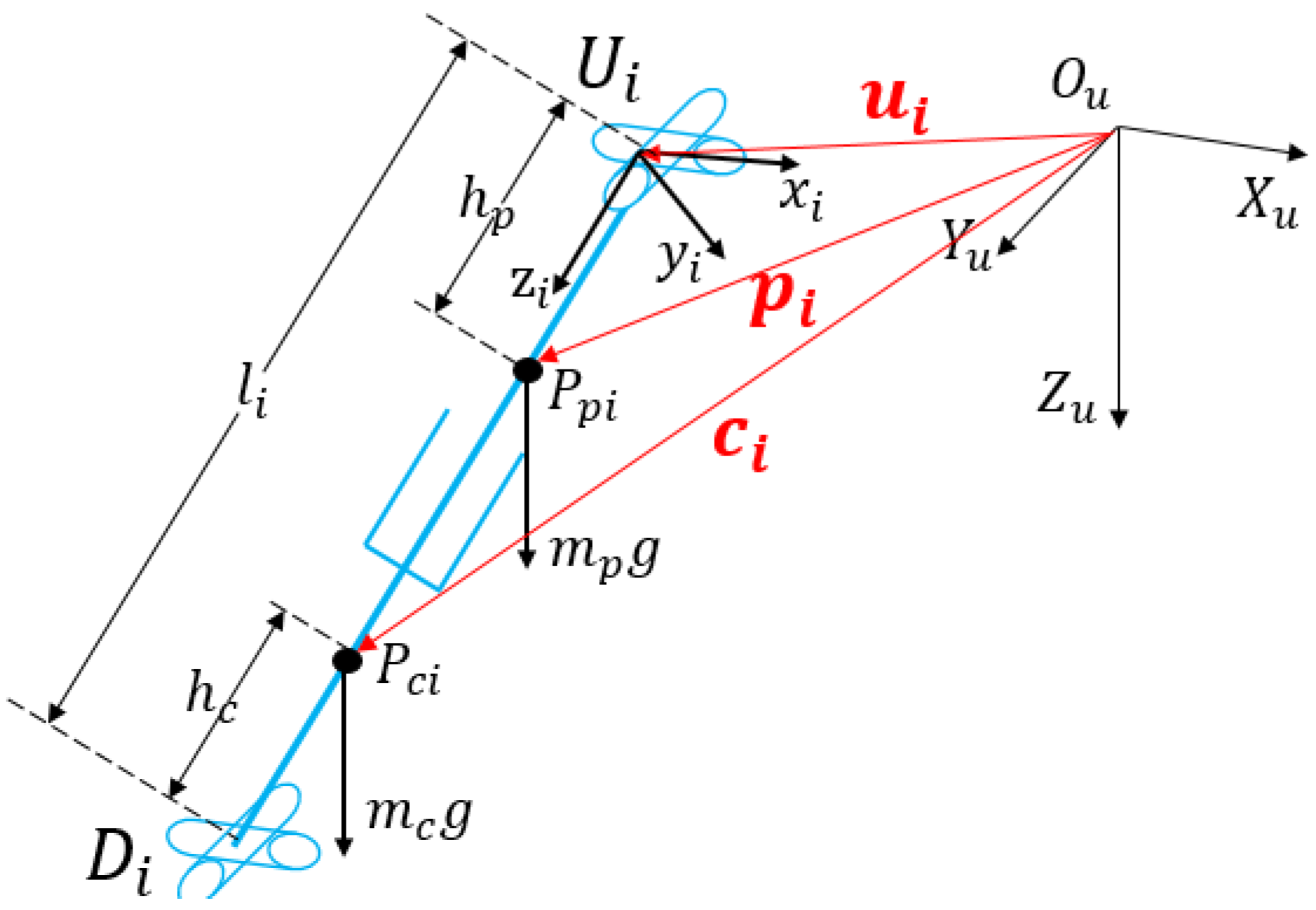
3.1.3. Analysis of Kinetic and Potential Energy of the Telescopic Arm

The telescopic arm adds telescopic motion to the main arm movement, so the barycenter coordinates of the telescopic arm can be represented in the o u x u y u z u frame as:
P m 2 = ( l 5 l m 2 ) cos ( α ) cos ( γ ) ( l 5 l m 2 ) cos ( α ) sin ( γ ) ( l 5 l m 2 ) sin ( α ) + P b
where l 5 is the length of the overall gangway.
l m 2 is the distance from the barycenter of the telescopic arm to the end point of the gangway.
The kinetic energy of the telescopic arm can be obtained:
E k 2 = 1 2 P ˙ m 2 T m 2 P ˙ m 2 + 1 2 α ˙ T I 2 α ˙ + 1 2 γ ˙ T I 2 γ ˙
where m 2 is the mass of the telescopic arm;
I 2 is the rotational inertia matrix of the slewing mechanism, as follows:
I 2 = I x 2 0 0 0 I y 2 0 0 0 I z 2 .
The potential energy of the telescopic arm can be obtained:
E p 2 = m 2 g [ h b + ( l 5 l m 2 ) sin ( α ) ]

3.1.4. Transfer Gangway Dynamic Equations

According to the Lagrange equation, we can obtain:
d d t L θ ˙ u θ = τ
where L = E k i E p i , E k i and E p i are the kinetic energy and potential energy of the system, respectively. θ denotes the physical parameters of the driving joints inside the Lagrange equation, which are γ , α , and l 5 in this paper.
d d t E k i θ ˙ E k i θ + E p i θ = τ ( i = m , 1 , 2 )
When the transfer gangway is used to compensate for the three-dimensional displacement, E k i and E p i of the system includes the kinetic and potential energy of the slewing mechanism: the main arm and the telescopic arm.
According to the kinetic energy and potential energy of each part of the transfer gangway obtained above, the forces and moments of the slewing mechanism, pitch axis and telescopic arm can be obtained from Equation (12).
d d t ( E k m + E k 1 + E k 2 ) γ ˙ ( E k m + E k 1 + E k 2 ) γ + ( E p m + E p 1 + E p 2 ) γ = T 1 d d t ( E k m + E k 1 + E k 2 ) α ˙ ( E k m + E k 1 + E k 2 ) α + ( E p m + E p 1 + E p 2 ) α = T 2 d d t ( E k m + E k 1 + E k 2 ) l ˙ 5 ( E k m + E k 1 + E k 2 ) l 5 + ( E p m + E p 1 + E p 2 ) l 5 = F 5
According to the geometric relationship in Figure 4, the pitching motor’s tractive force can be obtained by:
F 4 sin ( β ) l b 2 = T 2

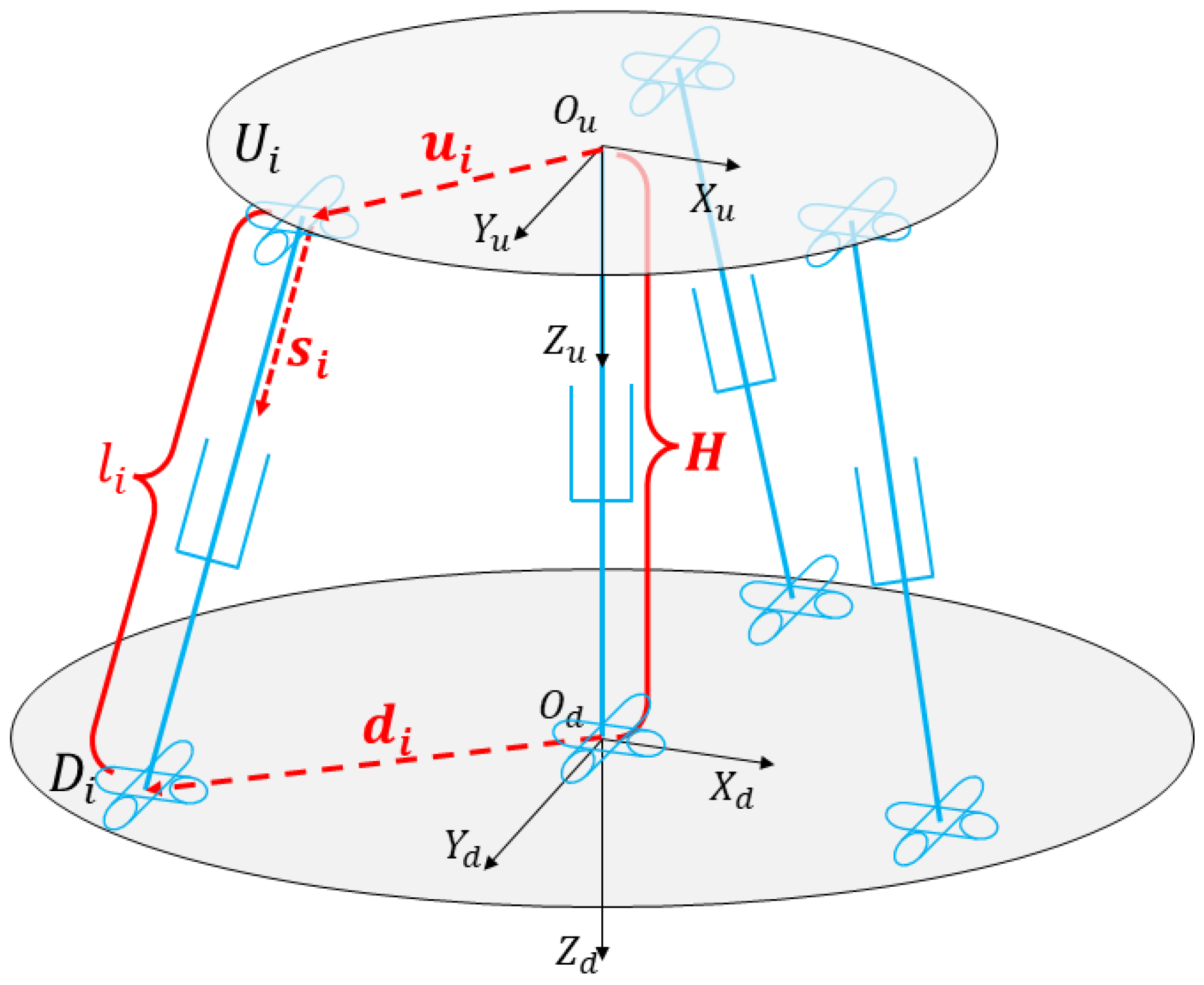
3.2. UPU/UP Stable Platform Dynamic Model

3.2.1. Dynamic Equations of Stable Platform

The stable platform’s frame is constructed as shown in Figure 5. The fixed platform and the moving platform are connected by U i (the hinge point centers of the i -th drive support chain) and D i (the hinge point centers of the stable platform), respectively. The origin is the point at which the drive support chain joins the fixed platform, and the z i -axis runs parallel to the drive support chain. The vector equation can be obtained:
u i + l i s i = H + d i
P p i , the push rod’s barycenter of the drive support chain, is shown in Figure 6. P c i is the cylinder’s barycenter in each drive support chain. The distances between P p i and U i are denoted by h p , and P c i and D i by h c . p i is the vector from O u to P p i , and c i is a vector along O u P c i . They are shown as follows:
p i = u i + h p s i
c i = u i + ( l i h c ) s i
where p i is the coordinate vector P p i of the push rod’s barycenter in the moving platform coordinate system;
c i is the coordinate vector P c i of the cylinder’s barycenter in the moving platform coordinate system;
It can be inferred from Equation (15) that the velocity of the barycenter of Hooke’s joint v D i is as follows:
v D i = v d + ω d × d i
It can be written as follows in the frame for drive support chains:
v i D i = R i O u v D i
where R i O u is the inverse matrix of the branch chain rotation matrix.
Similarly, the expressions for the velocity and acceleration of the barycenter of the rod and cylinder of the drive support chains can be obtained, and the details of the derivation can be found in [26]. To save space, this information will not be repeated. This section is omitted from this part owing to space constraints.
The velocities of their barycenter can be determined by putting it in the form of a Jacobi matrix.
v i P p i   = h p ω i i × s i i = h p l i v i D i , x v i D i , y 0
v i P c i = ( l i h c ) ω i i × s i i + l ˙ i s i i = 1 l i ( l i h c ) v i D i , x ( l i h c ) v i D i , y l i v i D i , z
J i D i , x , J i D i , y and J i D i , z are the first, second and third rows of J i D i , respectively. The angular velocity of the drive support chain in the branch chain frame is as follows:
ω i i = 1 l i J i D i , y J i D i , x 0 1 × 6 X ˙ d
The external pressures and moments acting on the fixed platform’s barycenter are indicated by f O u and n O u . m u denotes the mass of the fixed platform. v u denotes the horizontal velocity of the fixed platform. ω u denotes the rotational velocity of the fixed platform. The following equations can be used to explain the forces and moments acting at the fixed platform’s barycenter:
F u = f O u + m u g m u v ˙ u n O u I u ω ˙ u ω u × ( I u ω u )
m d denotes the mass of the moving platform. v d denotes the horizontal velocity of the moving platform. ω d denotes the rotational velocity of the moving platform. On the moving platform, the forces and moments applied at the barycenter can be expressed as follows:
F d = m d g m d v ˙ d I d ω ˙ d ω d × ( I d ω d )
Each drive support chain is composed of a rod and a cylinder. m p stands for the mass of the rod. m c stands for the mass of the cylinder. When all drive support chains are only subjected to gravity, I i p i stands for the inertia matrix of the rod. I i c i stands for the inertia matrix of the cylinder. The forces and moments acting on the i -th drive support chain’s rod and cylinder can thus be represented as follows:
F i p i = m p R i O u g m p v ˙ i p i I i p i ω ˙ i i ω i i × ( I i p i ω i i )
F i c i = m c R i O u g m c v ˙ i c i I i c i ω ˙ i i ω i i × ( I i c i ω i i )
According to the virtual work principle, it can be obtained:
δ q T τ + δ X d T ( F u + F d ) + i = 1 3 δ i x p i T F i p i + δ i x c i T F i c i = 0
where τ is the output force of mobile sub. δ q is the virtual displacement of τ . δ x i p i and δ x i c i are the virtual displacements of F i p i and F i c i , respectively.

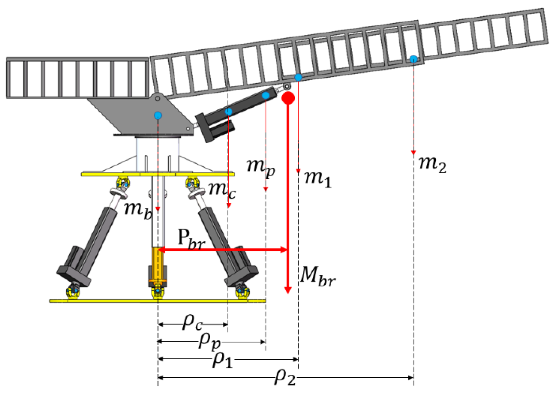
3.2.2. Dynamic Equations of Stable Platform under Dynamic Load

The dynamic load will be applied to the stable platform; loads of all components above the stable platform are shown in Figure 7. The distance of the mass and barycenter of the main components with respect to the barycenter of the fixed platform are represented in the figure, and these distances lead to the downward force of the components to produce a capsizing moment on the top of the fixed platform.
Where m b ,   m c ,   m p ,   m 1 ,   m 2 indicate the masses of the slewing mechanism, the cylinder of the pitching motor, the rod of the pitching motor, the main arm and the telescopic arm, respectively, ρ c , ρ p , ρ 1 and ρ 2 indicate the distances of the barycenter of the cylinder of the pitching motor, the rod of the pitching motor, the main arm and the telescopic arm from the pitch axis, respectively. The mass of the equivalent barycenter of the transfer gangway is represented by M b r , and the distance of the equivalent barycenter from the pitch axis is represented by P b r .
According to the geometric relationship in Figure 4, the length of the pitching motor can be obtained:
l 4 = l b 1 2 + l b 2 2 2 l b 1 l b 2 cos ( α + σ )
The angle between the pitching drive support chain and the horizontal direction can be obtained:
λ = π σ a r c cos ( l b 1 2 + l 4 2 l b 2 2 2 l b 1 l 4 )
The distance from the barycenter of the cylinder of the pitching drive support chain to the barycenter on the fixed platform can be obtained:
ρ c = ρ 0 + l c cos ( λ )
Similarly, the distances from the barycenter of the rod of the pitching drive support chain, the barycenter of the main arm and the barycenter of the telescopic arm to the barycenter of the fixed platform as follows:
ρ p = ( l 4 l p ) cos ( λ ) ρ 1 = l m 1 cos ( α ) ρ 2 = ( l 5 l m 2 ) cos ( α )
The external force and external moment at the barycenter of the fixed platform under the dynamic load can be expressed as:
f O u = 0 0 M b r g = 0 0 ( m b + m c + m p + m 1 + m 2 ) g
n O u = M b r g Ρ b r sin ( γ ) M b r g Ρ b r cos ( γ ) 0
where M b r = m b + m c + m p + m 1 + m 2 , Ρ b r = m c ρ c + m p ρ p + m 1 ρ 1 + m 2 ρ 2 M b r .
When the actual transfer operation is carried out in the offshore gangway, the fixed platform is subjected to the capsizing moment generated during the transfer of personnel (as shown in Figure 8), in addition to the force acting on the platform due to the constant load of its upper members and the dynamic load generated by the transfer gangway for ship motion compensation. Let a person of mass m p p start from the barycenter of the fixed platform and move along the transfer ramp with a speed of v p p ; the distance of the movement is l p p . The dynamics of the system are modeled below in this case.
During the transfer process, the person’s translational movement along the transfer gangway is accompanied by the rotary motion of the slewing mechanism, then the barycenter of the person in the o u x u y u z u frame can be expressed as:
P p p = l p p cos ( α ) cos ( γ ) l p p cos ( α ) sin ( γ ) l p p sin ( α ) + P b
The kinetic energy of the person can be obtained:
E k p p = 1 2 P ˙ m p p T m p p P ˙ m p p + 1 2 γ ˙ T I p p γ ˙
where I p p is the rotational inertia matrix of the slewing mechanism, as follows:
I p p = I x 3 0 0 0 I y 3 0 0 0 I z 3 ;
The potential energy of the person can be obtained:
E p p p = m p p g [ l p p sin ( α ) + P b z ]
The forces and moments of the slewing mechanism, pitch axis and telescopic arm can be regained from Equation (12).
d d t ( E k m + E k 1 + E k 2 + E k p p ) γ ˙ ( E k m + E k 1 + E k 2 + E k p p ) γ + ( E p m + E p 1 + E p 2 + E p p p ) γ = T 1 d d t ( E k m + E k 1 + E k 2 + E k p p ) α ˙ ( E k m + E k 1 + E k 2 + E k p p ) α + ( E p m + E p 1 + E p 2 + E p p p ) α = T 2 d d t ( E k m + E k 1 + E k 2 + E k p p ) l ˙ 5 ( E k m + E k 1 + E k 2 + E k p p ) l 5 + ( E p m + E p 1 + E p 2 + E p p p ) l 5 = F 5
The tractive force of the pitching motor can be regained:
F 4 = T 2 sin ( β ) l b 2
where T 1 , T 2 , F 5 , F 4 is the forces and moments of the slewing mechanism, pitch axis, telescopic arm and pitching motor.
For the stable platforms, the transfer gangway and the person are external dynamic loads. Considering these external dynamic loads, the external forces and external moments at the barycenter of the fixed platform can be expressed as follows:
f O u = 0 0 M b r g + m p p g = 0 0 ( m b + m c + m p + m 1 + m 2 + m p p ) g
n O u = ( M b r g Ρ b r + m p p ρ p p ) sin ( γ ) ( M b r g Ρ b r + m p p ρ p p ) cos ( γ ) 0
where ρ p p is the distance from the person to the pitch axis, as follows:
ρ p p = l p p cos ( α )
By replacing f O u and n O u into Equation (23), the dynamic model of the stable platform under the dynamic load of the gangway and person can be obtained.

4. Joint Simulation and Analysis Based on Adams and Matlab

Adams simulates the model created in Section 3 using the SolidWorks 3D structural model and the Matlab programming language. In this study, the exactitude of the model is confirmed by joint simulation. Under both dynamic and static load, the tractive forces of the three drive support chains of the stable platform are compared and studied. Finally, the compensation effect of the ship motion compensation scheme in this paper is simulated under the multi-degree of freedom excitation.
The assumption that ship motions are a collection of superimposed sinusoidal motions is one of the often-used simplified approaches in the marine engineering field. According to reference [27], without loss of generality, the roll and pitch excitation curves of the offshore gangway and the three-dimensional displacement curves of the transit destination relative to the ship established in this paper are shown in Figure 9 and Figure 10, respectively.
Hence, in Figure 5, the motion revolves around the y -axis, and α is the roll excitation angle. In Figure 5, β —which represents the pitch excitation angle—revolves around the x -axis. P e is the three-dimensional displacement curves of the transit destination relative to the ship.
Table 1 shows the specific data of the parameters used in this article.

4.1. Joint Simulation and Analysis of the Stable Platform Model under Static Load

First, the model under static load is calculated and analyzed. In this case, the effect of the transfer gangway on the dynamic load applied to the stable platform is not considered, and the transfer gangway is regarded as part of the fixed platform. In Figure 9, the moving platform receives the addition of α and β as the motion excitation. Figure 11 illustrates the tractive forces of the three drive support chains that are determined by the dynamic model and simulation. F1–F3 stand for tractive forces of the first, second and third drive support chains, respectively. The tractive force results from the Matlab dynamic model are denoted by MF, while the tractive force output from the Adams simulation is denoted by AF. The two curves in Figure 11 may be seen to be fairly close to one another. The two curves combined maximum inaccuracy under roll and pitch excitation is 0.96%. The tractive forces are generally consistent across periods, verifying the accuracy of the model.

4.2. Joint Simulation and Analysis of the Stable Platform Dynamic Model under Dynamic Load

After that, the model under dynamic load is calculated and analyzed. In actual operation, the stable platform is used to compensate for the ship’s roll and pitch motions. The transfer gangway is used to compensate for the three-dimensional displacement of the transfer destination relative to the ship to ensure that the end of it is stationary with respect to the transfer destination. The transfer gangway will apply dynamic load to the stable platform when compensating for the three-dimensional displacement of the ship. α and β in Figure 9 are applied to the moving platform as motion excitation, P e in Figure 10 is regarded as the displacement of the transfer destination relative to the end point of the gangway, which is the relative displacement of the end point of the gangway that needs to be compensated, and can also be regarded as the motion excitation of the end point of the gangway that will be added to the end point of the gangway. Figure 12 and Figure 13 display the tractive forces of the three drive support chains, the electric pitching and telescoping cylinders, and the driving torque of the slewing mechanism as determined by the dynamic model and simulation. Where F4 and F5 stand for the electric telescopic and pitching cylinders’ respective tractive forces, and T1 stands for the slewing mechanism’s driving torque. The two curves of the figures may be seen to be fairly close to one another. The two curves’ maximum inaccuracy under the dynamic load is 0.83%. The tractive forces are generally consistent across periods, verifying the accuracy of the dynamic model. The tractive forces of the three drive support chains of the stable platform differ greatly under dynamic load. The tractive force of the first drive support chain is negative (set the tractive force value to positive when the drive support chain generates a thrust and negative when the drive support chain generates a pull), and the tractive force of the second drive support chain is 2–3 times the tractive force of the first and third drive support chains. Because the transfer gangway is arranged in parallel with the first and second drive support chains, the third drive support chain is on the opposite side, and the second drive support chain is close to the gangway, so the obtained law is in line with the actual situation.
The comparison of the tractive forces of the three drive support chains of the stable platform under static load or dynamic load is shown in Figure 14. It can be observed that the tractive forces of all three drive support chains have changed, among which the tractive force of the first drive support chain is reduced by 52%. The tractive force of the second drive support chain has changed most obviously; it has increased by 283%. The tractive force of the third drive support chain has increased by 26%, indicating that the dynamic load has a great influence on the tractive forces of the drive support chains of the stable platform.

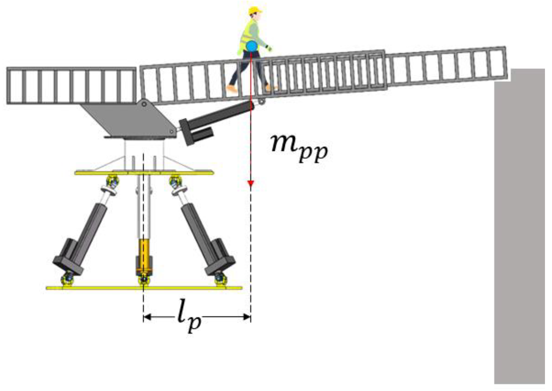
4.3. Joint Simulation and Analysis of the Stable Platform Dynamic Model during Personnel Transfer Operation

Finally, a calculation and analysis are performed on the model during the actual personnel transfer activity. The individual transferring people will also place a dynamic load on the offshore gangway while it is being used. In Figure 9, the motion excitation is concurrently added to the moving platform as α and β , whereas in Figure 10, the motion excitation is simultaneously added to the gangway’s end point as P e . The modeling calculations were performed at m p p of 10 kg, 40 kg, 70 kg and 100 kg, respectively, considering the equipment carried by the person. Figure 15 shows the driving forces of the three drive support chains determined by the dynamic model. It can be seen from the figure that the driving force of the second and third drive support chains increases with increasing mass, the personnel gradually approaches the end of the gangway and the driving force of the first drive support chain changes from positive to negative when the mass is 70 kg, and this phenomenon is more obvious when the mass is 100 kg. Figure 16 and Figure 17 show the traction forces of the three drive support chains determined by the dynamics model and simulation for m p p of 100 kg. The two curves of the figures may be seen to be fairly close to one another. Under dynamic load, the two curves’ combined maximum inaccuracy is 0.75%. The dynamic model’s accuracy is confirmed by the tractive forces’ general consistency throughout time. As the person gradually approaches the end point of the gangway, the tractive force of the first drive support chain changes from positive to negative. The tractive force of the second drive support chain gradually becomes larger and changes obviously. The tractive force of the third drive support chain also gradually becomes larger. The gangway is arranged in parallel with the first and second drive support chains; the third drive support chain is on the opposite side; and the second drive support chain is close to the gangway, so the obtained law is in line with the actual situation.

4.4. Analysis of the Compensation Effect of the Offshore Gangway

It can be seen from Section 2.1 that the ship motion compensation scheme in this paper compensates for the ship’s roll and pitch motion by using the stable platform, and compensates for the three-dimensional displacement of the transit destination relative to the ship by using the transfer gangway. To verify the stability compensation effect of the offshore gangway, in this section, the compensation scheme is simulated and analyzed under multi-degree-of-freedom excitation based on the dynamic model in this paper.
Under the motion excitation in Figure 9 and Figure 10. The response analysis of the end-point position of the gangway with and without compensation control is carried out; the results are shown in Figure 18 and Figure 19, respectively. In Figure 18, the position change of the end point of the gangway without compensation control differs greatly from Figure 10, which proves that the offshore gangway system cannot compensate for the relative displacement of the transfer destination and the end point of the gangway in this case. From the curve in Figure 19, the maximum error of the three-dimensional trajectory curve at the end of the gangway with the three-dimensional trajectory curve in Figure 10 is 0.432 m, 0.433 m and 0.20 m in the x, y, z directions with the maximum error rate of 15.56%, 16.98%, 1.91% in the three directions with compensation control. The curve overlap between Figure 19 and Figure 10 is 83%, which proves that the offshore gangway system can compensate for the relative position deviation between the transfer destination and the end of the gangway through compensating control, and that this ship motion compensation scheme can compensate for 83% of the ship motion compared to no ship motion compensation.

5. Conclusions

A dynamic model of the mixed offshore gangway under dynamic load is built in this paper. The tractive force of each joint of the transfer gangway is obtained using Lagrange equations, and then the dynamic model of the transfer gangway is built. The dynamic load applied to the stable platform by the transfer gangway is concretized using the equivalent center of gravity method. After that, the Jacobi matrix of each branch is solved. Finally, the stable platform’s dynamic model is established through virtual work.
Adam’s simulation model was used to validate the accuracy of the Matlab mathematical model. The maximum error between the simulation model and the mathematical model under multi-degree-of-freedom excitation is 0.83%.
The dynamic load applied to the stable platform by the transfer gangway has a large effect on the tractive forces of the drive support chains of the stable platform. After considering the dynamic load, the tractive force of the first drive support chain is negative, and the tractive force of the second drive support chain is 2–3 times greater than the tractive force of the first and third drive support chains. With the same excitation, the tractive force of the second drive support chain is 2.83 times higher than that under the static load, which has a certain guiding significance for the subsequent structural optimization and control system design of the mixed structure offshore gangway.
The person transfer procedure is compatible with the model established. The maximum error between the simulation model and the mathematical model after considering the movement of people on the transfer gangway is 0.75%. The tractive force of the first drive support chain of the stable platform changes from positive to negative when the personnel transfer operation is carried out, which is worthy of follow-up study and has certain guiding significance for the practical application of the mixed structure offshore gangway.
Based on the dynamics model in this paper, we propose compensating the ship’s roll and pitch motion by the stable platform, and the transfer gangway is used to compensate for the three-dimensional displacement of the transfer destination relative to the ship. This ship motion compensation scheme can compensate 83% of the ship motion compared with no ship motion compensation.
The dynamics model established in this paper provides an important theoretical basis for the subsequent trajectory planning, control system design and practical application of the mixed structure offshore gangway. In future work, we will focus on the establishment of a prototype based on the offshore gangway in this paper and use it as a basis to establish a more complete and accurate dynamic model, followed by research and testing of its stability control algorithm.

Author Contributions

Conceptualization and methodology, J.Q., W.Q. and A.N.; software, J.Q. and W.Q.; validation, J.Q., S.W., G.H. and Y.S.; writing—original draft preparation, G.H.; writing—review and editing, J.Q., A.N., S.W. and Y.S.; supervision, S.W., G.H. and Y.S.; funding acquisition, S.W. All authors have read and agreed to the published version of the manuscript.

Funding

This work was financially supported by the National Key Research and Development Program of China (Project No. 2018YFC0309003), the National Natural Science Foundation of China (Project No. 52101396) and China Fundamental Research Funds for the Central Universities (Project No. 3132022207, 3132022341). Shenghai Wang was supported by the China Scholarship Council for 18 months of study at Georgia Institute of Technology.

Institutional Review Board Statement

Not applicable.

Informed Consent Statement

Not applicable.

Data Availability Statement

Not applicable.

Conflicts of Interest

The authors declare no conflict of interest.

References

  1. Chen, G.; Yu, W.; Li, Q.; Wang, H. Dynamic modeling and performance analysis of the 3-PRRU 1T2R parallel manipulator without parasitic motion. Nonlinear Dynam. 2017, 90, 339–353. [Google Scholar] [CrossRef]
  2. Yan, M.; Ma, X.; Bai, W.; Lin, Z.; Li, Y. Numerical simulation of wave interaction with payloads of different postures using OpenFOAM. J. Mar. Sci. Eng. 2020, 8, 433. [Google Scholar] [CrossRef]
  3. Cai, Y.; Zheng, S.; Liu, W.; Qu, Z.; Zhu, J.; Han, J. Adaptive robust dual-loop control scheme of ship-mounted Stewart platforms for wave compensation. Mech. Mach. Theory 2021, 164, 104406. [Google Scholar] [CrossRef]
  4. Liang, L.; Le, Z.; Zhang, S.; Li, J. Modeling and controller design of an active motion compensated gangway based on inverse dynamics in joint space. Ocean Eng. 2020, 197, 106864. [Google Scholar] [CrossRef]
  5. Dong, Q.; Guo, X.; Li, X.; Lu, W.; Yang, J. Coupled dynamics between a turret-moored fpso and a semi-submersible accommodation platform. Ocean Eng. 2021, 229, 108764. [Google Scholar] [CrossRef]
  6. Li, B.; Liang, H.; Chen, X.; Araujo, R. Study of telescopic gangway motions in time domain during offshore operation. Ocean Eng. 2021, 230, 108692. [Google Scholar] [CrossRef]
  7. Xu, Y.; Liao, H.; Liu, L.; Wang, Y. Modeling and robust H-infinite control of a novel non-contact ultra-quiet Stewart spacecraft. Acta Astronaut. 2015, 107, 274–289. [Google Scholar] [CrossRef]
  8. Liu, S.; Zhu, Z.; Sun, Z.; Cao, G. Kinematics and dynamics analysis of a three-degree-of-freedom parallel manipulator. J. Cent. S. Univ. 2014, 21, 2660–2666. [Google Scholar] [CrossRef]
  9. Wang, Z.P.; Zhao, D.F.; Zeng, G.Y. The dynamic model of a 6-DOF parallel mechanism. Mach. Des. Manuf. 2018, 1, 71–74+77. [Google Scholar]
  10. Muralidharan, V.; Mamidi, T.K.; Guptasarma, S.; Nag, A.; Bandyopadhyay, S. A comparative study of the configuration-space and actuator-space formulations of the Lagrangian dynamics of parallel manipulators and the effects of kinematic singularities on these. Mech. Mach. Theory 2018, 130, 403–434. [Google Scholar] [CrossRef]
  11. Kalani, H.; Rezaei, A.; Akbarzadeh, A. Improved general solution for the dynamic modeling of Gough–Stewart platform based on principle of virtual work. Nonlinear Dynam. 2016, 83, 2393–2418. [Google Scholar] [CrossRef]
  12. Enferadi, J.; Akbarzadeh Tootoonchi, A. Inverse dynamics analysis of a general spherical star-triangle parallel manipulator using principle of virtual work. Nonlinear Dynam. 2010, 61, 419–434. [Google Scholar] [CrossRef]
  13. Yang, X.; Wu, H.; Chen, B.; Kang, S.; Cheng, S. Dynamic modeling and decoupled control of a flexible Stewart platform for vibration isolation. J. Sound Vib. 2019, 439, 398–412. [Google Scholar] [CrossRef]
  14. Arian, A.; Isaksson, M.; Gosselin, C. Kinematic and dynamic analysis of a novel parallel kinematic Schönflies motion generator. Mech. Mach. Theory 2020, 147, 103629. [Google Scholar] [CrossRef]
  15. Wen, S.; Yu, H.; Zhang, B.; Zhao, Y.; Lam, H.; Qin, G.; Wang, H. Fuzzy identification and delay compensation based on the force/position control scheme of the 5-DOF redundantly actuated parallel robot. Int. J. Fuzzy Syst. 2017, 19, 124–140. [Google Scholar] [CrossRef] [Green Version]
  16. Cheng, G.; Shan, X. Dynamics analysis of a parallel hip joint simulator with four degree of freedoms (3R1T). Nonlinear Dynam. 2012, 70, 2475–2486. [Google Scholar] [CrossRef]
  17. Yang, X.; Wu, H.; Li, Y.; Kang, S.; Chen, B.; Lu, H.; Lee, C.K.; Ji, P. Dynamics and isotropic control of parallel mechanisms for vibration isolation. IEEE/ASME Trans. Mechatron. 2020, 25, 2027–2034. [Google Scholar] [CrossRef]
  18. Mendes Lopes, A.; Almeida, F. The generalized momentum approach to the dynamic modeling of a 6-dof parallel manipulator. Multibody Syst. Dyn. 2009, 21, 123–146. [Google Scholar] [CrossRef]
  19. Xin, G.; Deng, H.; Zhong, G. Closed-form dynamics of a 3-DOF spatial parallel manipulator by combining the Lagrangian formulation with the virtual work principle. Nonlinear Dynam. 2016, 86, 1329–1347. [Google Scholar] [CrossRef]
  20. Filipovic, M.; Djuric, A.; Kevac, L. The significance of adopted Lagrange’s principle of virtual work used for modeling aerial robots. Appl. Math. Model. 2015, 39, 1804–1822. [Google Scholar] [CrossRef]
  21. Tian, H.; Ma, H.; Xia, J.; Ma, K.; Li, Z. Stiffness analysis of a metamorphic parallel mechanism with three configurations. Mech. Mach. Theory 2019, 142, 103595. [Google Scholar] [CrossRef]
  22. Liu, Z.; Tao, R.; Fan, J.; Wang, Z.; Jing, F.; Tan, M. Kinematics, dynamics, and load distribution analysis of a 4-PPPS redundantly actuated parallel manipulator. Mech. Mach. Theory 2022, 167, 104494. [Google Scholar] [CrossRef]
  23. Cammarata, A. Optimized design of a large-workspace 2-DOF parallel robot for solar tracking systems. Mech. Mach. Theory 2015, 83, 175–186. [Google Scholar] [CrossRef]
  24. Pedrammehr, S.; Nahavandi, S.; Abdi, H. Closed-form dynamics of a hexarot parallel manipulator by means of the principle of virtual work. Acta Mech. Sinica-PRC 2018, 34, 883–895. [Google Scholar] [CrossRef]
  25. Zhao, Y.; Qiu, K.; Wang, S.; Zhang, Z. Inverse kinematics and rigid-body dynamics for a three rotational degrees of freedom parallel manipulator. Robot. Cim. Int. Manuf. 2015, 31, 40–50. [Google Scholar] [CrossRef]
  26. Niu, A.; Wang, S.; Sun, Y.; Qiu, J.; Qiu, W.; Chen, H. Dynamic modeling and analysis of a novel offshore gangway with 3UPU/UP-RRP series-parallel mixed structure. Ocean Eng. 2022, 266, 113122. [Google Scholar] [CrossRef]
  27. Wang, A.; Wei, Y.; Han, H.; Guan, L.; Zhang, X.; Xu, X. Ocean Wave Active Compensation Analysis of Inverse Kinematics for Mixed Boarding System based on Fuzzy Algorithm. In Proceedings of the 2018 OCEANS-MTS/IEEE Kobe Techno-Oceans, Kobe, Japan, 28–31 May 2018. [Google Scholar]
Figure 1. Structural components of the offshore gangway: 1—telescopic arm; 2—main arm; 3—pitching motor; 4—fixed platform; 5—moving platform; 6—follower branch chain; 7—drive support chains; 8—slewing mechanism; 9—transfer platform.
Jmse 11 00077 g001
Figure 2. The offshore gangway’s frames.
Jmse 11 00077 g002
Figure 3. Dimensions of the transfer gangway and frames of the slewing mechanism.
Jmse 11 00077 g003
Figure 4. Dimensions of the transfer gangway and frames of the telescopic arm.
Jmse 11 00077 g004
Figure 5. The stable platform’s frames.
Jmse 11 00077 g005
Figure 6. Dimensions and the drive support chain’s frame.
Jmse 11 00077 g006
Figure 7. The barycenter of the transfer gangway and its horizontal location.
Jmse 11 00077 g007
Figure 8. The capsizing moment generated by human movement.
Jmse 11 00077 g008
Figure 9. Curves of motion excitation.
Jmse 11 00077 g009
Figure 10. Curves of the three-dimensional displacement.
Jmse 11 00077 g010
Figure 11. Tractive force of each drive support chain under the static load.
Jmse 11 00077 g011
Figure 12. Tractive force of each drive support chain of the stable platform under the dynamic load.
Jmse 11 00077 g012
Figure 13. Tractive force or driving torque of each joint of the transfer gangway under the dynamic load.
Jmse 11 00077 g013
Figure 14. Tractive force of each drive support chain under static load or dynamic load.
Jmse 11 00077 g014
Figure 15. Tractive force of each drive support chain of the stable platform under personnel masses of 10 kg, 40 kg, 70 kg and 100 kg, respectively.
Jmse 11 00077 g015
Figure 16. Tractive force of each drive support chain of the stable platform under under personnel mass of 100 kg.
Jmse 11 00077 g016
Figure 17. Tractive force or driving torque of each joint of the transfer gangway under the actual person transfer operation.
Jmse 11 00077 g017
Figure 18. Trajectory of the end point of the offshore gangway with compensation control.
Jmse 11 00077 g018
Figure 19. Trajectory of the end point of the offshore gangway without compensation control.
Jmse 11 00077 g019
Table 1. Parameters and state variables.
Md (kg)Mp (kg)mc (kg)m1 (kg)m2 (kg)hb (m)lb1 (m)lb2 (m)lm1 (m)
23.346.811.4732.02625.2290.4231.520.2260.768
Disclaimer/Publisher’s Note: The statements, opinions and data contained in all publications are solely those of the individual author(s) and contributor(s) and not of MDPI and/or the editor(s). MDPI and/or the editor(s) disclaim responsibility for any injury to people or property resulting from any ideas, methods, instructions or products referred to in the content.

