Article

Hydrodynamic Design of Fixed Hydrofoils for Planing Craft

by
Egidio D’Amato
1,
Immacolata Notaro
2,
Vincenzo Piscopo
1,* and
Antonio Scamardella
1
1
Department of Science and Technology, University of Naples “Parthenope”, Centro Direzionale Isola C4, 80143 Naples, Italy
2
Department of Engineering, University of Campania “Luigi Vanvitelli”, Via Roma 29, 81031 Aversa, Italy
*
Author to whom correspondence should be addressed.
J. Mar. Sci. Eng. 2023, 11(2), 246; https://doi.org/10.3390/jmse11020246
Submission received: 23 December 2022 / Revised: 12 January 2023 / Accepted: 17 January 2023 / Published: 18 January 2023
(This article belongs to the Special Issue Seakeeping and Performance in Waves of Marine Vessels)

Abstract

:
The employment of fixed hydrofoils on existing planing craft is becoming a widely investigated topic, thanks to the opportunity of reducing the total drag forces and the consumptions of main engines, with a positive impact also in terms of air pollutant emissions in the atmosphere. The design of fixed hydrofoils for planing craft is investigated after developing the wing hydrodynamic model, capable of capturing the main forces acting on the craft longitudinal plane. An iterative procedure is developed to solve the nonlinear equilibrium equations and detect the minimum thrust configuration of the fixed hydrofoils at the cruise speed. The new iterative procedure allows investigating the entire design space of fixed hydrofoils and detecting the best configuration for both new and existing craft, with a positive impact in terms of time effort amount and design efficiency. A simplified seakeeping model is also developed to evaluate the impact of fixed hydrofoils on the craft hydrodynamics in a seaway. The USV01 planing craft is assumed as reference for the case study. The wing optimization procedure is employed and the seakeeping analysis in the foil-borne mode is subsequently performed by a set of dedicated codes developed in Matlab. The obtained results are discussed and some suggestions for the reliable design of fixed hydrofoils are provided.

1. Introduction

Hydrofoil technology has been increasingly applied since the first decade of the 20th century. Starting from the first pioneering attempts, dated back to the 19th century, during the last decades significant efforts have been undertaken to improve the design and efficiency of fixed hydrofoils, in terms of resistance in calm water and seakeeping performances. In fact, the proper selection of the wing profile, chord, aspect ratio and incidence angle is a basic issue for the rational design of fixed hydrofoils, in order to minimize the propeller thrust at the cruise speed, conditional on the fulfilment of both hydrostatic and hydrodynamic restraint criteria. Really, most past research activities focused on the hydrodynamic analysis of hydrofoils for new craft, but in the last years the interest of researchers throughout the world grew fast, thanks to the possibility of also installing fixed hydrofoils on existing craft, with a positive impact in terms of resistance at high speed and consumptions. In fact, it is well-known that the foil-borne mode allows for decreasing the drag forces, as regards the displacement and planing modes, therefore reducing the consumption of main engines and the emission of air pollutants, namely nitrate and sulphate oxides, among others, in the atmosphere.
Nevertheless, as it will be further discussed in Section 2, there is still a need to develop complete wing hydrodynamic models and proper optimization procedures of the foil layout, with the main aim of minimizing craft resistance at cruise speed. In this respect, most past research activities focused on the hydrodynamic analysis of hydrofoils with a preliminarily known configuration; but the optimum design of fixed hydrofoils has not been investigated until now, to the best of the authors’ knowledge. Besides, some attempts have been recently undertaken to investigate craft hydrodynamic performances in a seaway in the foil-borne mode; but in this case it is also necessary to connect the fulfilment of both hydrostatic and hydrodynamic criteria to the optimum design procedure, in order to ensure that the selected foil configuration is not only the minimum thrust one, but also that it is reliable in terms of stability and seakeeping performances. These research activities have been carried out within the research project TME, namely, “Processo automatico per l’implementazione di Tecnologie per la Mobilità Efficiente Navale”, currently funded by the Italian Ministry for Economic Development, and having as one of the key findings the development of design procedures devoted to the installation of fixed hydrofoils onboard planing craft.
The paper is organized as follows. Section 2 provides a brief review of hydrofoil technology and past installations of hydrofoils on planing craft and high-speed vessels. Section 3 focuses on the wing hydrodynamic model and provides a new iterative procedure for the optimum wind design; the seakeeping equations for planing craft in the foil-borne mode are also developed. The main data of the reference craft endorsed in the analysis are provided in Section 4, while the case study is outlined in Section 5, where the incidence of the wing main parameters on the minimum propeller thrust and cruise speed is systematically investigated. In this respect, three reference layouts are selected for the preliminary assessment of the transverse stability and the subsequent seakeeping analysis. Finally, Section 6 focuses on the main findings of the study, also in view of future research activities. All calculations have been performed by a set of dedicated programmes, developed in Matlab MathWorks [1].

2. The Hydrofoil Technology

2.1. A Brief Historical Review

The first pioneering attempts of equipping a boat with hydrofoils date back to the middle of the 19th century, when Thomas Moy installed for the first time a set of fully submerged hydrofoils on a craft operating in the Surrey Canal, located south of London, and verified that the boat was lifted “quite out of the water” when towed. In the same years, Forlanini equipped a conventional 1.65 t craft with a set of hydrofoils that achieved the speed of 38 kn in Lake Maggiore, Italy. However, the first recognized research on hydrofoil technology dates back to the first decade of the 20th century, when Meacham [2] explained the relevant working principle and described some experimental activities on this research topic. In the following decades additional experimental attempts were undertaken by Bell and Baldwin that established the world speed record of 70.86 mph with the well-known HD-4 craft in the Baddeck Bay, on 9th September 1919. Additional developments were gained in the 1950s by the Royal Canadian Navy, that developed several naval craft equipped with fixed hydrofoils. Most research activities on hydrofoil technology started at the beginning of the 1960s, when von Schertel [3] developed and extensively tested the tandem surface-piercing foil system. In the same years, Krack and Gross [4] investigated the hydrodynamic behaviour of a surface-piercing foil craft, while Ellsworth [5] developed the first mathematical model for fully submerged and actively stabilized foils. In parallel to the above-mentioned research activities on fully submerged foils, additional studies were carried out on surface piercing foils, with reference to the assessment of the lift and drag forces, generally determined according to aeronautical practices, with the inclusion of the free surface effect [6,7]. In the following years, the endorsement of numerical methods became very popular. In this respect, Plotkin [8] investigated the potential flow of a uniform stream over a thin symmetric hydrofoil by the Keldysh and Lavrentiev method. Yeung and Bouger [9] applied an integral-equation technique, based on the Green theorem, and satisfying the free surface condition in a linearized form, to solve the steady-state wave-resistance problem for thick hydrofoils. Duncan [10] carried out an experimental campaign, to investigate the drag forces exerted by the NACA 0012 hydrofoil at constant speed with a 5 deg angle of attack. Kennel and Plotkin [11] applied a second-order potential flow method to investigate the lift and drag forces exerted by thin two-dimensional hydrofoils, moving at constant speed at a fixed depth below the sea water level, including nonlinear corrections for the free-surface boundary condition. Bai and Han [12] investigated the effect of non-linear free surface conditions for two-dimensional hydrofoils moving at constant speed with shallow submergence by the finite-element method, based on the Hamilton principle. More recently, Xie and Vassalos [13] developed a potential-based panel method to evaluate the steady potential flow around three-dimensional hydrofoils under the sea water level, employing constant-strength doublets and source density distributions over the foil body surface and a Dirichlet-type boundary condition instead of the Neumann-type one.
Following the main outcomes of past research activities, in the last decade special attention was paid to the assessment of the hydrodynamic performances of fixed hydrofoils by advanced numerical methods, and to the employment of optimal control strategies for movable hydrofoils. As concerns the first topic, the effect of the angle of attack on the hydrodynamic performances of two and three-dimensional hydrofoils were studied by the well-known Reynolds-Averaged Navier-Stokes (RANS) equations, combined with different turbulence models [14,15,16]. As concerns the second research topic, several studies were performed on the employment of optimal control strategies for movable hydrofoils to improve the hydrodynamic performances in a seaway [17,18,19]. Finally, in the last years, attention was also paid to the application of hydrofoils on existing craft, as will be further discussed in Section 2.2.

2.2. Application of Foils to Planing Craft and High-Speed Vessels

Starting from the pioneering works on planing craft by Clement and Blount [20], Savitsky [21] and Hubble [22] were mainly devoted to the resistance assessment in calm water and the design of new hard-chine planing hulls; a variety of research activities have been undertaken to improve the resistance and seakeeping performances of planing craft in a seaway. By way of example, Weymouth et al. [23] investigated the heave and pitch motion performances of a planing craft in irregular sea conditions. Begovic et al. [24] focused on the statistical properties of planing hull motions and accelerations in irregular sea. De Luca et al. [25] developed a new warped hard chine systematic series, investigated the relevant seakeeping performances in head sea condition [26], as well as the nonlinear vertical motions in regular wave conditions [27].
In the last two decades, some attempts were also undertaken to equip high-speed vessels and planing craft with fixed hydrofoils, to reduce the bare hull resistance and increase the seakeeping performances in a seaway. Sclavounos and Borgen [28] equipped a high-speed vessel with a bow hydrofoil, acting as a passive heave and pitch motion-control device in waves, with the main aim of increasing the seakeeping performances in a seaway. They also carried out a sensitivity study, devoted to investigate the incidence of the hydrofoil location on the reduction of heave and pitch motions at high-speed. Bi et al. [29] analysed the hydrodynamic performances of a planing craft with a fixed hydrofoil in regular waves by numerical methods and experimental testing activities. They systematically investigated the incidence of the angle of attack and submergence of fixed hydrofoils on the seakeeping performances of a planing craft by a RANS-VOF solver. Recently, Maram et al. [30] investigated the employment of fully submerged hydrofoils, with tandem configuration and NACA 4412 profile, by systematically varying the angle of attack and the longitudinal separation. Apart from the above-mentioned studies, there is still the need of further investigating the employment of fixed hydrofoils on existing craft, to reduce the resistance in calm water without decreasing the seakeeping performances in a seaway. This matter is outlined in Section 3, where the iterative design procedure for fixed hydrofoils and the seakeeping motion equations are outlined.

3. Wing Hydrodynamics

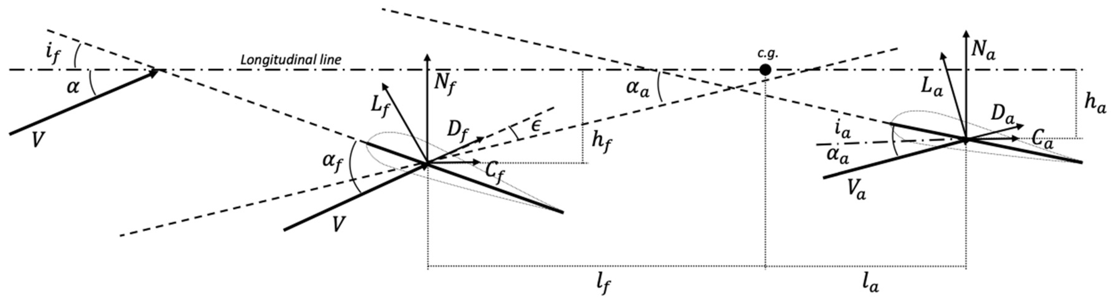
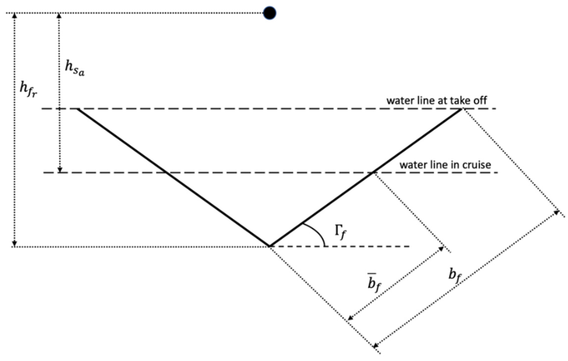
3.1. The Hydrodynamic Model

Let us consider a planing craft as a rigid body, symmetric as regards its longitudinal plane, and let us introduce three reference frames: (i) a left-handed body reference frame O X b Y b Z b , with origin in the craft centre of gravity, X b ( Z b ) axis forward (upward) positive and Y b axis normal to the craft symmetry plane; (ii) a left-handed hydrodynamic reference frame O X w Y w Z w , with origin in the craft centre of gravity, X w axis coincident with the speed direction and Z w axis downward positive; and (iii) a fixed inertial reference frame O X e Y e Z e , oriented as the standard NED (North-East-Down) reference tern. The orientation of the body reference frame, as regards the inertial one, is determined by the Euler angles of roll, pitch and yaw motions. The symmetric freedom degrees characterize the longitudinal dynamics of the planing craft, while the asymmetric ones define the latero-directional dynamics.
Based on previous remarks, some assumptions are required to design the hydrofoils: (i) the craft and its foils are considered as a rigid body, symmetric as regards its longitudinal plane; (ii) the generalized force vector is computed as the sum of forces and moments exerted on each part, according to the principle of superposition of effects; (iii) the wings are fixed with no control mechanisms; (iv) the dynamics is slow enough to ensure that the angular velocity vector is almost negligible; and (v) the only symmetric degrees of freedom are considered so focusing on the craft equilibrium in the longitudinal plane.
The hydrodynamic actions exerted by the hydrofoils are represented by the lift and drag forces (moments), applied on (around) the hydrodynamic centre of each foil, located at 1/4 of the chord. The normal N k and parallel C k forces, exerted by each foil, as depicted in Figure 1, are provided in the body reference frame by Equations (1) and (2):
N k = L k cos Γ k cos α + D k sin α
C k = D k cos α L k cos Γ k sin α
having denoted by the subscript k = { f , a } the force exerted by the forward ( f ) and afterward ( a ) foils, respectively; Γ k the dihedral angle of the foil (see Figure 2) and α the global angle of attack, namely the angle formed by the X w and X b axes of the hydrodynamic and body reference frames. The angles of attack of the forward and afterward foils are each other different and are provided by Equations (3) and (4), respectively:
α f = α + i f
α a = α + i a ϵ
where i f ( i a ) is the incidence angle of the forward (afterward) wing and ϵ is the downwash angle, related to the water flow deviation due to the front wing. The global equilibrium equations depend on the craft mass, as well as on the location and geometry of the afterward and forward wings. The horizontal, vertical and rotational equilibrium conditions in the craft symmetry plane are provided by Equations (5)–(7):
F x = C f + C a + m g sin α = F p
F z = N f + N a m g cos α = 0
M y = N f l f C f h f N a l a C a h a + M f + M a + F p h p = 0
having denoted by: m the mass of the craft; g the gravity acceleration; F p the propeller thrust; l f ( l a ) and h f ( h a ) the longitudinal and vertical distances between the craft centre of gravity and the hydrodynamic centre of the forward (afterward) wing; M f ( M a ) the hydrodynamic pitching moment exerted by the forward (afterward) wing and h p the vertical distance between the craft centre of gravity and the propeller axis.
The normal/parallel forces and the pitch moment exerted by each wing can be resembled into a non-dimensional form [31,32,33] by Equation (8):
C N k = N k q k S ¯ k   ;   C C k = C k q k S ¯ k   ;   C m k = M k q k S ¯ k c k  
where q k = 1 2 ρ V k 2 is the dynamic pressure, c k is the mean aerodynamic chord of the k-th foil, S ¯ k = μ k S k is the effective planform surface of the k-th wing, with μ k as a speed-dependent non-dimensional parameter lying in the interval [0, 1] and S k the k-th planform surface. In fact, the foils are fully submerged at the take-off condition, but at the maximum speed condition they are partly emerged, provided that they are fixed and no control mechanisms are considered to eventually reduce the lift coefficient and counterbalance the increase of the dynamic pressure. Hence, the global equilibrium conditions can be resembled into a non-dimensional form according to Equations (9)–(11):
F x q S ¯ f = C C f + η a S ¯ a S ¯ f C C a + m g q f S ¯ f sin α = F p q f S ¯ f
F z q S ¯ f = C N f + η a S ¯ a S ¯ f C N a m g q f S ¯ f cos α = 0
M q S ¯ f c f = C N f   l ˜ f C C f   h ˜ f η a S ¯ a l ˜ a S ¯ f C N a η a S ¯ a h ˜ a S ¯ f C C a + C M f + η a S ¯ a c a S ¯ f c f C M a + F p q f S f   h ˜ p = 0
having denoted by: η a = q a / q f the ratio between the dynamic pressure on the afterward and forward wings; l ˜ f = l f / c f ( l ˜ a = l a / c f ) the non-dimensional longitudinal distance of the forward (afterward) wing; h ˜ f = h f / c f ( h ˜ a = h a / c f ) the non-dimensional vertical distance of the forward (afterward) wing and h ˜ p = h p / c f the non-dimensional vertical distance of the propeller axis, as regards the craft centre of mass. It is noticed that in the previous equations the aerodynamic forces, exerted on the emerged part of the craft, are not considered because negligible as regards the hydrodynamic ones, provided that the air density is much lower than the sea water one. The immersion coefficients are embodied to define the effective spans b ¯ f = μ f b f and b ¯ a = μ a b a of the forward and afterward wings with respect to the geometric spans b f and b a , as well as the effective aspect ratios A R ¯ f = b ¯ f 2 / S ¯ f and A R ¯ a = b ¯ a 2 / S ¯ a . At the take-off speed the craft is just out of water, as depicted in Figure 2, which implies that μ f = μ a = 1 , while at the cruise speed the effective planforms of the forward and afterward wings can be determined by Equation (12):
μ f = ( h f r h s a ) ( b f / 2 ) sin Γ a   ;   μ a = ( h a r h s a ) ( b a / 2 ) sin Γ a
where h s a = h f r b ¯ f 2 sin Γ f is the distance between the craft centre of gravity and the sea water surface; b a and Γ a are the span and the dihedral angle of the afterward wing.
The completion of the equilibrium equations passes through the evaluation of the wing hydrodynamic characteristics, in terms of lift, drag and pitching moment coefficients, based on the 2D airfoil parameters, depending on the angle of the attack and the Reynolds number, according to Equation (13):
C l k = C l ( α k , R e k )   ;   C d k = C d ( α k , R e k )   ; C m k = C m ( α k , R e k )
Such coefficients are known for standard NACA foils [34,35]. Alternatively, they can be computed by high-order panel methods or CFD analysis. However, the 2D characteristics are true for infinite span wings, but for finite span wings some corrective factors need to be added to account for tip vortices [36]. In this respect, the lift, drag and pitching moment coefficients of the 3D wing are determined by Equation (14):
C L k = C l k ( α k , R e k ) 1 + 2 / A R ¯ k   ; C D k = C d k + C L k 2 π A R ¯ k e k   ; C M k = C m k A R ¯ k A R ¯ k + 2
having denoted by e k the Oswald coefficient, depending on the dynamic pressure distribution over the wing. It is noticed that the drag coefficient is computed by the so-called drag polar distribution, consisting of two components, the former due to the parasite foil drag, the latter due to the tip vortices and depending on the lift coefficient of the 3D wing.

3.2. The Iterative Procedure for Wing Design

The equilibrium equations, provided by Equations (9)–(11), shall be fulfilled at any steady-state condition. In current analysis the take-off condition, corresponding to the minimum desired speed with the craft out of water and both wings completely immersed ( μ f = μ a = 1 ), is selected as design criterion to solve the Equations (10) and (11). The required propeller thrust at this condition is subsequently determined by solving the Equation (9). Based on these assumptions, a simplified design procedure can be implemented after selecting: (i) the craft weight and the position of the centre of gravity and propeller axis; and (ii) the longitudinal/vertical location, the incidence angle and the span of both wings. The iterative procedure is applied to solve the non-linear equation system, by imposing a tentative value of the wing surfaces, to evaluate the relevant chord and aspect ratio, according to Equations (15) and (16):
S f = m g [ ( C C a h ˜ a C m a c a c f + C N a l ˜ a ) cos α C N a l ˜ p sin   α ] q f [ C m f C N a C m a C N f c a / c f + C C a C N f ( h ˜ a h ˜ p ) C C f C N a ( h ˜ f h ˜ p ) + C N a C N f ( l ˜ a + l ˜ f ) ]
S a = m g [ ( C m f C C f ( h ˜ f h ˜ p ) + C N f l ˜ f ) cos α + C N f h ˜ p sin α ] η a q f [ C m f C N a C m a C N f c a / c f + C C a C N f ( h ˜ a h ˜ p ) C C f C N a ( h ˜ f h ˜ p ) + C N a C N f ( l ˜ a + l ˜ f ) ]
Once convergence is reached and the wing surfaces S f and S a are determined, the optimal cruise speed is computed by solving the minimization problem of the propeller thrust according to Equation (17):
min V T n o = q S ¯ f [ C D f cos | α | C L f cos Γ f sin α + η a S ¯ a / S ¯ f ( C D a cos α C L a cos Γ a sin α ) ]
conditional on the fulfilment of the equilibrium equations provided by Equations (10) and (11), to account for the partial submergence of the wings, the craft speed, the planform ratios of the forward μ f and afterward μ a wings and the angle of attack α .

3.3. Seakeeping Equations

The coupled heave-pitch motion equations in the time-domain are easily determined by the Cummins [37] approach, according to Equation (18):
{ ( m + a 33 ) q ¨ 3 + b 33 q ˙ 3 + c 33 q 3 + a 35 q ¨ 5 + b 35 q ˙ 5 + c 35 q 5 = F 3 ( t ) a 53 q ¨ 3 + b 53 q ˙ 3 + c 53 q 3 + ( i 55 + a 55 ) q ¨ 5 + b 55 q ˙ 5 + c 55 q 5 = F 5 ( t )
having denoted by: m ( i 55 ) the mass (pitch moment of inertia) of the craft; a i j , b i j and c i j the added mass, hydrodynamic damping and restoring coefficients of the foils; q ¨ i , q ˙ i and q i the acceleration, velocity and displacement components of the i-th motion mode, with i = 3, 5 for the heave and pitch motions, respectively; F i the time-dependent random excitation force/moment of the i-th motion mode. The hydrodynamic coefficients are determined by the unsteady lift formulation developed by Theodorsen [38], who solved the problem of the unsteady flow around a flat plat oscillating in heave and pitch motions. The added mass components for wings with high aspect ratios are determined by Equation (19):
a 33 = ρ π 4 i b ¯ i c i 2 ;   a 35 = a 53 = ρ π 4 i b ¯ i c i 2 l i ;   a 55 = ρ π 4 i b ¯ i c i 2 l i 2
where reference is made to Section 3.1 for the meaning of all physical quantities. The hydrodynamic damping coefficients in the encounter frequency domain are determined by Equation (20):
b 33 = ρ π U i b ¯ i c i R e { T = i } ;   b 35 = ρ π U i b ¯ i c i [ c i 4 + U ω e I m { T = i } l i R e { T = i } ] b 53 = ρ π U i b ¯ i c i l i R e { T = i } ;   b 55 = + ρ π U i b ¯ i c i [ l i 2 R e { T = i } U ω e l i I m { T = i } c i 4 l i ]
having denoted by U the vessel speed and T = i the Theodorsen function that, in turn, depends on the reduced frequency k f , i according to Equation (21):
T = i = H 1 ( 2 ) ( k f , i ) H 1 ( 2 ) ( k f , i ) + i H o ( 2 ) ( k f , i )   ;   k f , i = ω e c i 2 U
In the previous equations ω e is the encounter wave frequency, while H o ( 2 ) and H 1 ( 2 ) are the 0-th and 1-st order Hankel functions of the second kind. As concerns the restoring coefficients, they are the sum of two contributions, the former due to the hydrodynamic field exerted by the submerged part of the foil, the latter due to the surface-piercing effect. The frequency-dependent restoring coefficients are determined by Equation (22), according to the unsteady lift formulation [38]:
c 33 , f = ρ π U ω e i b ¯ i c i I m { T = i }   ;   c 35 , f = ρ π U i b ¯ i c i [ U R e { T = i } + ω e l i I m { T = i } ] c 53 , f = ρ π U ω e i b ¯ i c i l i I m { T = i }   ;   c 55 , f = ρ π U i b ¯ i c i l i [ U R e { T = i } + ω e l i I m { T = i } ]
As concerns the surface piercing effect, the restoring components can be approximately determined by Equation (23), assuming that the lift coefficient of the hydrofoils remains unchanged, as regards the steady-state configuration:
c 33 , s p = ρ U 2 i c i cot g ( Γ i ) C L i ;   c 35 , s p = c 35 , s p 0   ;   c 55 , s p = ρ U 2 i c i l i 2 cot g ( Γ i ) C L i
Finally, the frequency-dependent heave f 3 and pitch f 5 forces per unit wave amplitude are determined by Equations (24) and (25), where k = ω 2 / g is the wave number at infinite water depth and ω is the absolute circular wave frequency:
f 3 ( ω e ) = ρ π ω i b ¯ i c i [ i U T = i c i 4 ω e ] exp [ k ( z i i l i ) ]
f 5 ( ω e ) = ρ π ω i b ¯ i c i l i [ i U T = i c i 4 ω e ] exp [ k ( z i i l i ) ]
After determining the frequency-dependent forces per unit wave amplitude, the random exciting forces in the time-domain are assessed by Equation (26):
F i ( t ) = R e k = 1 N f i ( ω e k ) 2 S ( ω k ) Δ ω k exp [ i ( ω e k t + φ k ) ]
having denoted by: S ( ω k ) the wave spectrum at the absolute circular frequency ω k , Δ ω k the wave frequency interval, ω e k the encounter circular frequency, depending on the Doppler shift, and φ k the random phase of the k-th component, uniformly distributed in the interval [ 0 , 2 π ] .

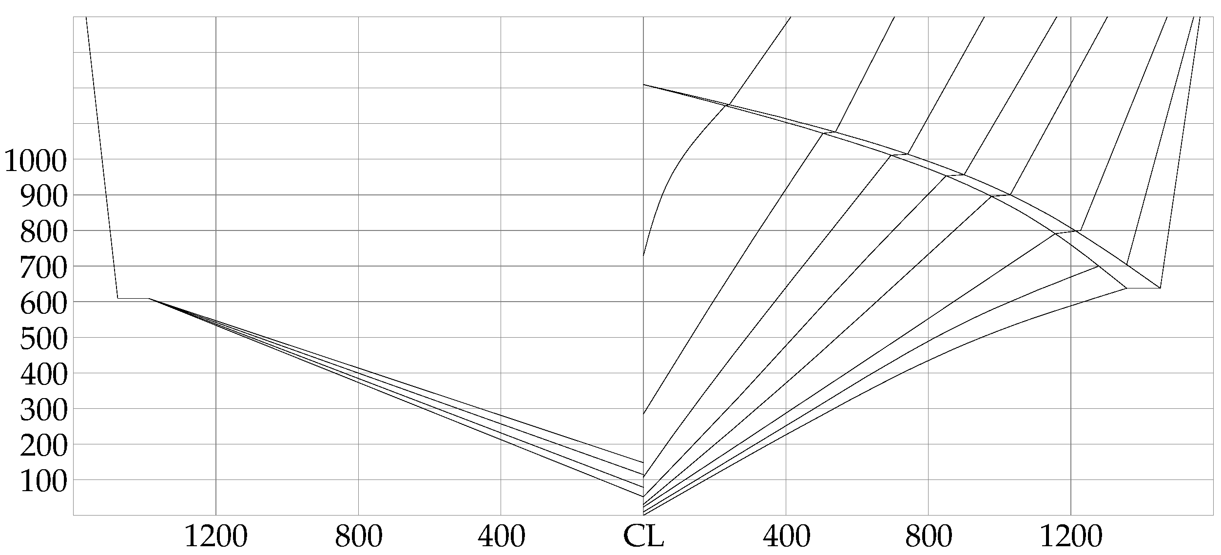
4. Reference Planing Craft
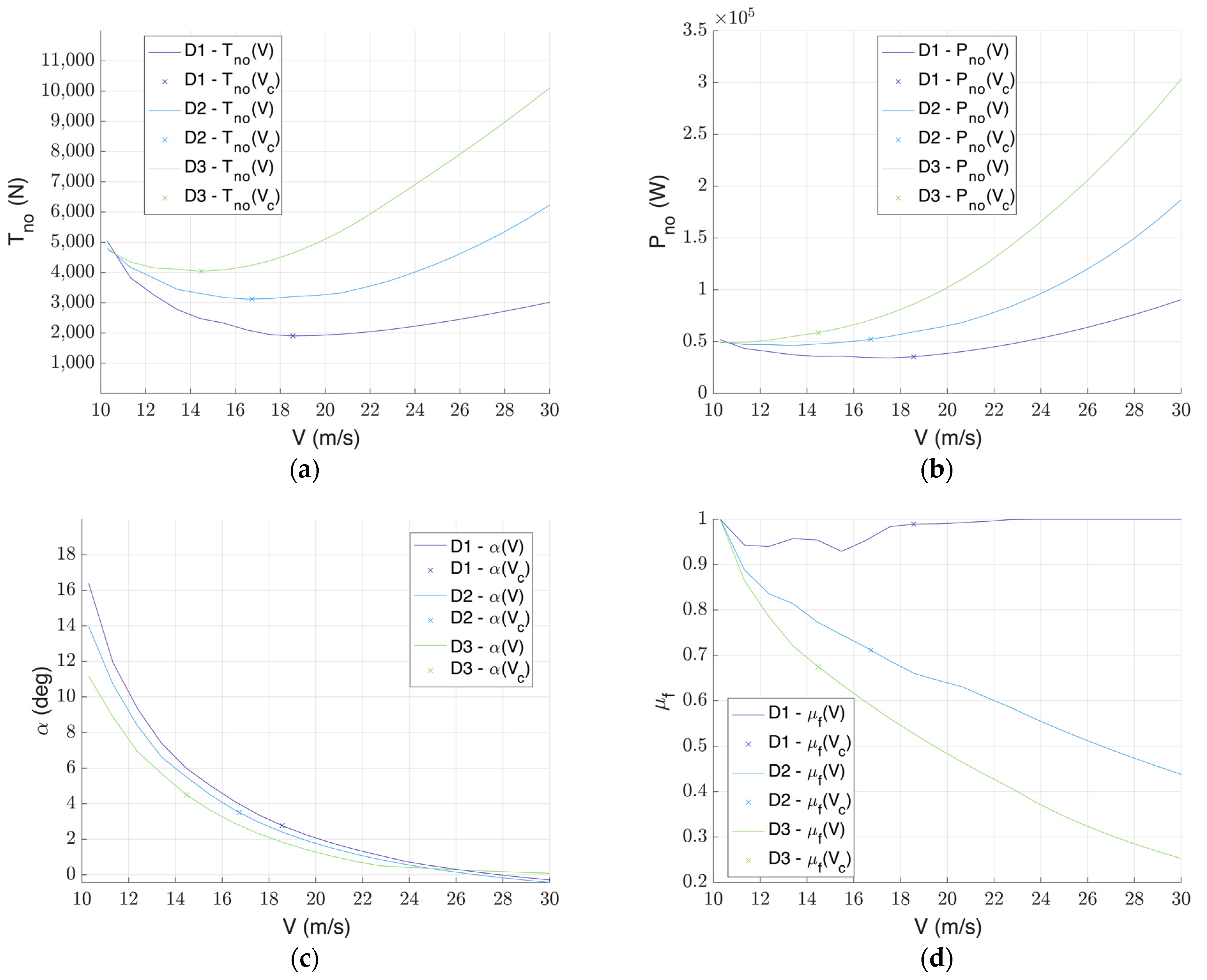
The planing craft USV01 [29] is assumed as reference vessel for the hydrofoil design and seakeeping analysis. The main dimensions are listed in Table 1, while Figure 3 provides the relevant section lines. This craft was assumed as reference vessel in the benchmark study, recently carried out by Bi et al. [29], who systematically varied the submergence and the angle of attack of the fixed hydrofoils and investigated the relevant impact on the resistance in calm water and in waves. The take-off and maximum speeds were selected in the range typical of planing craft.

5. Case Study

5.1. Wing Design and Selection

The iterative procedure, outlined in Section 3.2, is carried out by a dedicated programme developed in Matlab [1], where the minimum problem, provided by Equation (17), is dealt with by a nonlinear-adapted gradient-based optimization function. The afterward foil is located at the craft stern and has a 0 deg incidence angle, so as it is aligned with the craft bottom surface. The location and the incidence angle of the forward foil, instead, are iteratively varied in order to investigate the entire design space and detect the best candidate configurations. In all cases, the NACA 2412 profile is employed for both foils and the wing mass is considered negligible as regards the craft one, so regarding the centre of gravity as fixed.
Figure 4a–d show the main characteristics of the forward foil at the optimum cruise condition, namely the minimum propeller thrust, the cruise speed, the angle of attack and the immersion coefficient, for each configuration of the above-mentioned parameters in the range of i f between 0 and 5 deg and l f between 0 and 3.5 m, respectively. As it can be gathered from Figure 4a, the minimum propeller thrust at the cruise speed increases with the incidence angle and decreases with the distance of the forward wing from the craft centre of gravity. While the first outcome is almost predictable, the second one mainly depends on the trend of the immersion coefficient and angle of attack at the cruise condition. In fact, as shown by Figure 4d, the immersion coefficient is almost equal to 1 at low incidence angles, so resulting in an almost totally submerged wing. For this reason, the required angle of attack is minimum when the incidence angle is equal to 0.0 deg and corresponds to the highest cruise speed, where the minimum value of the drag forces occurs, as it can be gathered by Figure 4b,c. The best hydrofoil configuration can be selected by these response surfaces, once the desired cruise speed. Hence, three design configurations, with the forward foil located at 3.5 m from the craft centre of gravity, are selected with different values of the incidence angle.
The proper selection of the foil incidence angle, in fact, mainly depends on the local hull forms, if the additional requirement of making the foils retractable into the hull needs to be fulfilled. The relevant main dimensions are reported in Table 2. The aspect ratio of foils is always high to reduce, as far as possible, the induced drag forces, without exceeding the craft local breadth.
Figure 5a–d show the results of the three reference configurations, in terms of minimum thrust, minimum power, angle of attack and immersion coefficient of the forward foil at various speeds. The thrust initially decreases with the craft speed reaching the minimum value, which is the optimum one corresponding to the cruise speed. Figure 5b shows the trend of the needed power with the speed. Analogously to the needed thrust, as expected, the power increases with the speed. Figure 5c shows the angle of attack distribution versus the craft speed that, as predictable, decreases. Figure 5d provides the immersion coefficient, that decreases with the speed for the D2 and D3 configurations. The first one, instead, features the hydrofoil with the lowest incidence angle, whose equilibrium can be reached with the immersion coefficient μ f = 1 , namely with the hydrofoil completely immersed. It is noticed that in all cases μ a = 1 , which implies that the afterward foil is always fully submerged.
Finally, the variation of the pitch moment with respect to the lift is computed to investigate the longitudinal static stability of the three selected configurations, as it usually occurs for an aircraft with fixed controls. In this respect, the derivative C m C L must be less than 0 to guarantee the longitudinal stability. Figure 6 shows that each configuration is stable, even if the longitudinal stability increases with the incidence angle of the forward hydrofoil.

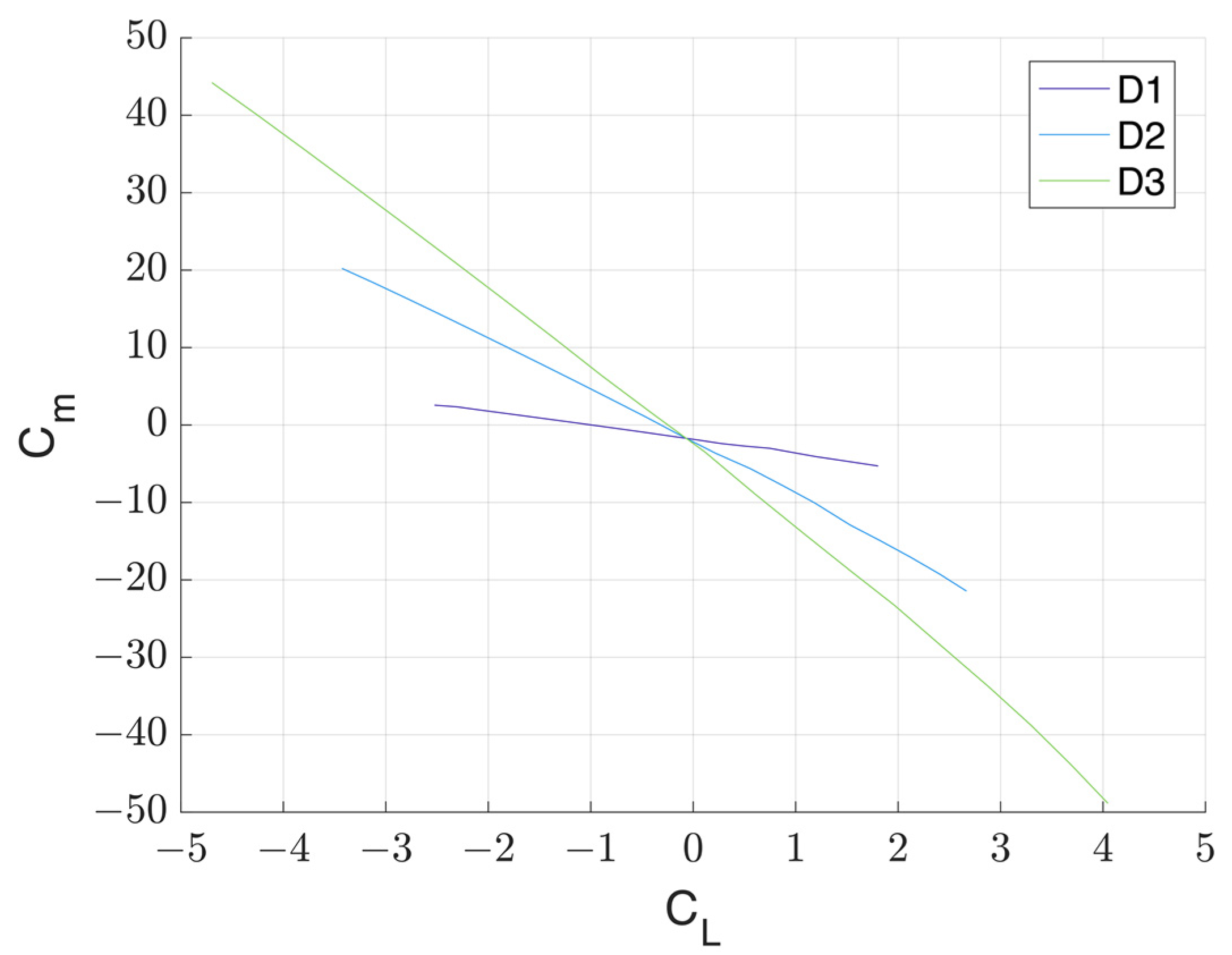
5.2. Assessment of Metacentric Height

Before performing the seakeeping analysis of the selected foil configurations, the metacentric height of the three candidate layouts needs to be preliminarily assessed to estimate the craft transverse stability in the foil-borne mode. In this respect, the candidate configuration D1 is not further analysed, as both foils are fully submerged at the cruise speed. As concerns the remaining two configurations, the metacentric height G M in the foil-borne mode is determined by Equation (27), in compliance with the Annex 6 of the High-Speed Craft Code [39], bearing in mind that in both cases the afterward foil is fully submerged at the cruise speed, while a certain submergence of the forward foil occurs, as it can be gathered by Figure 5d:
G M = C L f μ f S f cos Γ f C L f μ f S f cos Γ f + C L a S a cos Γ a ( μ f b f cos Γ f 2 tan Γ f h s a )
The lift coefficients and the metacentric height at the cruise speed are provided by Table 3, from which it is gathered that the D2 configuration is has a higher transverse stability as regards the D3 one, which implies that it is selected for the seakeeping analysis carried out in Section 5.3. Reference is made to Table 2 for the main data of the selected configuration.

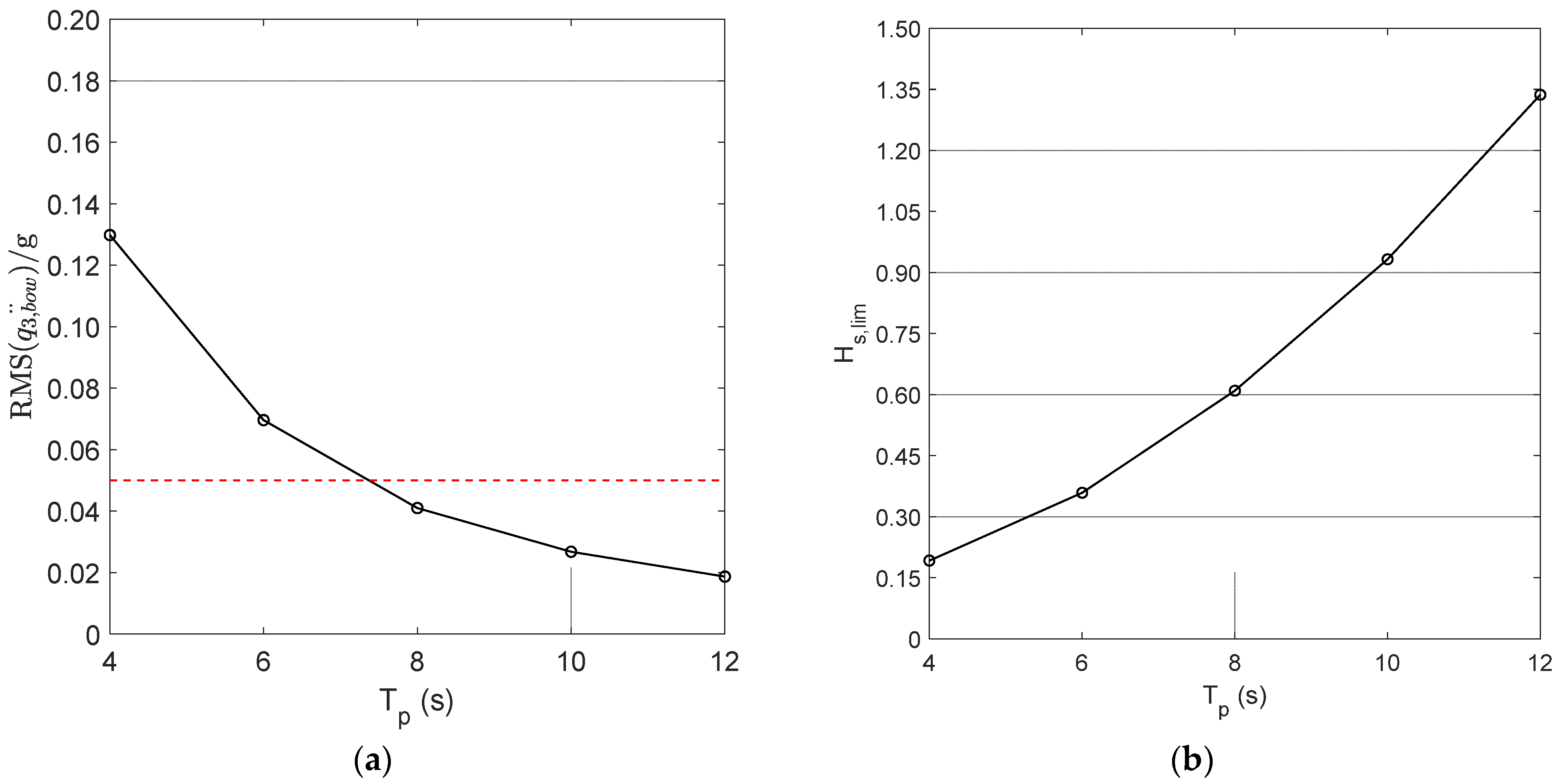
5.3. Seakeeping Analysis

The time history of the random wave elevation is obtained by the JONSWAP spectrum with a significant wave height H s equal to 0.50 m and a wave peak period T p ranging from 4 to 12 s, with 2 s step. Figure 7a provides the Root Mean Square (RMS) of the combined heave-pitch vertical acceleration at the craft bow, in correspondence of the forward foil, together with the dashed red line representing the limit value equal to 0.05 g that is a widely recognized international standard for 2 h exposure to a given motion, causing sea sickness in about 10% of non-acclimated adults. Figure 7b provides the maximum significant wave height that complies with the limit value of the vertical acceleration at the bow, as a function of the wave peak period. Current results confirm that the maximum allowable significant wave height in the foil-borne mode is compatible with the typical operational profile of a planing craft, so proving that hydrofoils represent a reliable solution, not only in terms of resistance in calm water, but also with reference to the craft dynamics in a seaway.

6. Conclusions

A new iterative procedure for the design of fixed hydrofoils to be installed on planing craft has been developed and applied. The iterative procedure for wing design allows efficiently detecting the best configuration that allows minimizing the propeller thrust at the cruise speed. The time-domain motion equations for surface-piercing foils have been developed to investigate the vertical acceleration in a seaway in the foil-borne mode. Based on current results, the following main outcomes have been achieved:
i
The iterative procedure for the wing design is revealed to be effective for the detection of the minimum thrust configuration, once the main parameters of the afterward and forward wings are selected;
ii
The heave-pitch seakeeping equations for the foil-borne mode are developed, including the restoring components due to the surface-piercing effect;
iii
The case study proves that the iterative procedure for wing design allows obtaining a set of wing configurations that need to be further analysed to ensure a satisfactory value of the metacentric height in the foil-borne mode. Besides, based on the results of seakeeping analysis the selected wing layout complies with the vertical acceleration limit criterion at the craft bow for 2 h exposure.
The obtained results are encouraging for further research devoted to the optimization of the wing design for new and existing planing craft, and for the development of active weather routing algorithms that are currently endorsed for displacement ships [40], to increase the safety of ship and navigation in the foil-borne mode.

Author Contributions

Conceptualization, E.D., I.N., V.P. and A.S.; methodology, E.D., I.N. and V.P.; software, E.D., I.N. and V.P.; validation, E.D. and A.S.; formal analysis, I.N. and V.P.; data curation, E.D. and I.N.; writing—original draft preparation, I.N. and V.P.; writing—review and editing, E.D. and A.S.; funding acquisition, V.P. and A.S. All authors have read and agreed to the published version of the manuscript.

Funding

The research was funded within the Project TME “Processo automatico per l’implementazione di Tecnologie per la Mobilità Efficiente Navale” CUP B66G2100090005, Fondo per la Crescita Sostenibile–Sportello “Fabbrica intelligente” PON I&C 2014-2020, D.M. 5 marzo 2018 Capo III.

Institutional Review Board Statement

Not applicable.

Informed Consent Statement

Not applicable.

Data Availability Statement

Data are available upon request to the authors. A closed-form version of the Matlab code can be shared at the end of the TME project upon request to the authors.

Conflicts of Interest

The authors declare no conflict of interest.

References

  1. MathWorks. Matlab User Guide R2022b; MathWorks: Natick, MA, USA, 2022. [Google Scholar]
  2. Meacham, W.M. Hydroplane boats: Latest type of high-speed craft. Sci. Am. 1906, 94, 188–189. [Google Scholar] [CrossRef] [Green Version]
  3. Von Schertel, A. Hydrofoils—The changing scene. Hover. Craft Hydrofoil 1963, 2, 13–16. [Google Scholar]
  4. Krack, R.C.; Gross, J.G. Experience with the hydrofoil craft Denison. In Proceedings of the SNAME Hydrofoil Symposium, Seattle, WA, USA, 13–14 May 1965; p. 2e. [Google Scholar]
  5. Ellsworth, W.M. The U.S. Navy Hydrofoil Development Program; Technical Note SDD-0H50-62; David Taylor Model Basin: Potomac, MD, USA, 1970. [Google Scholar]
  6. Kaplan, P.; Breslin, J.P. Evaluation of the theory for the flow pattern of a hydrofoil of finite span. J. Ship Res. 1960, 4, 13–29. [Google Scholar] [CrossRef]
  7. Johnson, R.S. Prediction of lift and cavitation characteristics of hydrofoil-strut arrays. Mar. Technol. 1965, 2, 57–69. [Google Scholar] [CrossRef]
  8. Plotkin, A. The Thin-hydrofoil thickness problem including leading-edge corrections. J. Ship Res. 1975, 19, 122–129. [Google Scholar] [CrossRef]
  9. Yeung, R.W.; Bouger, Y.C. A hybrid integral-equation method for steady two-dimensional ship waves. Int. J. Numer. Methods Eng. 1979, 14, 317–336. [Google Scholar] [CrossRef]
  10. Duncan, J.H. The breaking and non-breaking wave resistance of a two-dimensional hydrofoil. J. Fluid Mech. 1983, 126, 507–520. [Google Scholar] [CrossRef]
  11. Kennell, C.; Plotkin, A. A second order theory for the potential flow about thin hydrofoils. J. Ship Res. 1984, 28, 55–64. [Google Scholar] [CrossRef]
  12. Bai, K.J.; Han, J.H. Localized finite-element method for the nonlinear steady waves due to a two-dimensional hydrofoil. J. Ship Res. 1994, 38, 42–51. [Google Scholar] [CrossRef]
  13. Xie, N.; Vassalos, D. Performance analysis of 3D hydrofoil under free surface. Ocean Eng. 2007, 34, 1257–1264. [Google Scholar] [CrossRef]
  14. Sharma, A.; Sarwara, M.S.; Singh, H.; Swarup, L.; Sharma, R.K. CFD and real time analysis of a symmetric airfoil. Int. J. Res. Aeronaut. Mech. Eng. 2014, 2, 84–93. [Google Scholar]
  15. Liu, J.; Hekkenberg, R.G. Hydrodynamic characteristics of twin-rudders at small attack angles. In Proceedings of the 12th International Marine Design Conference, Tokyo, Japan, 11–14 May 2015; pp. 177–188. [Google Scholar]
  16. Kandil, M.A.F.; Elnady, A.O. CFD analysis of GOE 387 airfoil. IOSR J. Mech. Civ. Eng. 2017, 14, 80–85. [Google Scholar]
  17. Bai, J.; Kim, Y. Control of the vertical motion of a hydrofoil vessel. Ships Offshore Struct. 2010, 5, 189–198. [Google Scholar] [CrossRef]
  18. Liu, S.; Niu, H.; Zhang, L.; Xu, C. Modified adaptive complementary sliding mode control for the longitudinal motion stabilization of the fully-submerged hydrofoil craft. Int. J. Nav. Archit. Ocean Eng. 2019, 11, 584–596. [Google Scholar] [CrossRef]
  19. Deng, Y.; Xianku, Z.; Namkyun, I.; Kailey, L. Compound learning tracking control of a switched fully-submerged hydrofoil craft. Ocean Eng. 2021, 219, 108260. [Google Scholar] [CrossRef]
  20. Clement, E.P.; Blount, D.L. Resistance tests of a systematic series of planing hull form. SNAME Trans. 1963, 71, 491–579. [Google Scholar]
  21. Savitsky, D. Hydrodynamics design of planing hulls. Mar. Technol. 1964, 1, 71–95. [Google Scholar] [CrossRef]
  22. Hubble, E.N. Resistance of Hard-Chine, Stepless Planing Craft with Systematic Variation of Hull Form, Longitudinal Center of Gravity and Loading; Technical Report AD0779864; David Taylor Model Basin: West Bethesda, MD, USA, 1974. [Google Scholar]
  23. Weymouth, G.D.; Wilson, R.V.; Stern, F. RANS computational fluid dynamics predictions of pitch and heave ship motions in head seas. J. Ship Res. 2005, 49, 80–97. [Google Scholar] [CrossRef]
  24. Begovic, E.; Bertorello, C.; Pennino, S.; Piscopo, V.; Scamardella, A. Statistical analysis of planing hull motions and accelerations in irregular head sea. Ocean Eng. 2016, 112, 253–264. [Google Scholar] [CrossRef]
  25. De Luca, F.; Pensa, C. The Naples warped hard chine hulls systematic series. Ocean Eng. 2017, 139, 205–236. [Google Scholar] [CrossRef] [Green Version]
  26. De Luca, F.; Pensa, C. The Naples Systematic Series—Second part: Irregular waves, seakeeping in head sea. Ocean Eng. 2019, 194, 106620. [Google Scholar] [CrossRef]
  27. Pigazzini, R.; De Luca, F.; Pensa, C. An experimental assessment of nonlinear effects of vertical motions of Naples systematic series planing hulls in regular waves. Appl. Ocean Res. 2021, 111, 102546. [Google Scholar] [CrossRef]
  28. Sclavounos, P.D.; Borgen, H. Seakeeping analysis of a high-speed monohull with a motion-control bow hydrofoil. J. Ship Res. 2004, 48, 77–117. [Google Scholar] [CrossRef]
  29. Bi, X.; Shen, H.; Zhou, J.; Su, Y. Numerical analysis of the influence of fixed hydrofoil installation position on seakeeping of the planing craft. Appl. Ocean Res. 2019, 90, 101863. [Google Scholar] [CrossRef]
  30. Maram, M.A.; Ghafari, H.R.; Ghassemi, H.; Ghiasi, M. Numerical Study on the Tandem Submerged Hydrofoils Using RANS Solver. Math. Probl. Eng. 2021, 2021, 8364980. [Google Scholar] [CrossRef]
  31. Anderson, J.D.; Bowden, M.L. Introduction to Flight; McGraw-Hill Higher Education: New York, NY, USA, 2005; Volume 582. [Google Scholar]
  32. Matveev, K.I.; Kornev, N. Dynamics and stability of boats with aerodynamic support. J. Ship Prod. Des. 2013, 29, 17–24. [Google Scholar] [CrossRef]
  33. Matveev, K.I. Modeling of longitudinal motions of a hydroplane boat. Ocean Eng. 2012, 42, 1–6. [Google Scholar] [CrossRef]
  34. Abbott, I.H.; Von Doenhoff, A.E. Theory of Wing Sections: Including a Summary of Airfoil Data; Courier Corporation: Washington, DC, USA, 2012. [Google Scholar]
  35. Eppler, R. Wing sections for hydrofoils-Part 2: Nonsymmetrical profiles. J. Ship Res. 1981, 25, 191–200. [Google Scholar]
  36. Raymer, D.P. Aircraft Design: A Conceptual Approach; American Institute of Aeronautics and Astronautics: Reston, VA, USA, 2018. [Google Scholar]
  37. Cummins, W.E. The impulse response function and ship motions. Schiffstechnik 1962, 9, 101–109. [Google Scholar]
  38. Theodorsen, T. General Theory of Aerodynamic Instability and the Mechanism of Flutter; NACA Technical Report n. 496; Langley, Aeronautical Lab.: Langley Field, VA, USA, 1949; p. 24p. [Google Scholar]
  39. The International Maritime Organization. International Code of Safety for High-Speed Craft, 2021 edition; The International Maritime Organization: London, UK, 2000. [Google Scholar]
  40. Pennino, S.; Gaglione, S.; Innac, A.; Piscopo, V.; Scamardella, A. Development of a new ship adaptive weather routing model based on seakeeping analysis and optimization. J. Mar. Sci. Eng. 2020, 8, 270. [Google Scholar]
Figure 1. Longitudinal forces scheme.
Jmse 11 00246 g001
Figure 2. Forward hydrofoil immersion characteristics.
Jmse 11 00246 g002
Figure 3. Section lines of the USV01 craft (all dimensions are in mm).
Jmse 11 00246 g003
Figure 4. Main parameters of forward foil at cruise speed: (a) minimum thrust, (b) cruise speed at minimum thrust, (c) angle of attack, and (d) immersion coefficient.
Jmse 11 00246 g004
Figure 5. Main parameters of selected configurations as a function of vessel speed: (a) minimum thrust, (b) minimum power, (c) angle of attack, and (d) immersion coefficient.
Jmse 11 00246 g005
Figure 6. Variation of the pitch moment with respect to the lift.
Jmse 11 00246 g006
Figure 7. Main parameters of selected configurations as a function of vessel speed: (a) RMS of vertical acceleration at the bow, (b) maximum allowable significant wave height.
Jmse 11 00246 g007
Table 1. Main properties of reference craft.
Overall length11.00 m
Overall breadth3.12 m
Moulded depth1.30 m
Design draught0.53 m
Centre of gravity longitudinal position from the stern4.19 m
Centre of gravity vertical position from the baseline0.80 m
Propeller axis vertical position from the baseline−0.30 m
Initial trim angle0.0 deg
Displacement at the full loaded condition8025 kg
Pitch moment of inertia60,000 kgm2
Deadrise angle at the stern18 deg
Take-off speed20 kn
Maximum speed30 kn
Table 2. Main properties of selected foil configurations.
Main ParametersD1D2D3
Forward foil span [m]3.123.123.12
Forward foil aspect ratio 21.4621.0220.60
Forward foil surface [m2]0.4530.4630.472
Forward foil incidence angle [deg]0.02.55.0
Forward foil longitudinal distance from CG [m]3.503.503.50
Forward foil dihedral angle [deg]252525
Afterward foil span [m]3.123.123.12
Afterward foil aspect ratio 15.9114.3611.86
Afterward foil surface [m2]0.6120.6780.821
Afterward foil incidence angle [deg]0.00.00.0
Afterward foil longitudinal distance from CG [m]4.194.194.19
Afterward foil dihedral angle [deg]101010
Table 3. Main data of foils at the cruise speed.
Reference ParametersD2D3
Cruise speed [m/s]17.014.5
Lift coefficient of forward foil0.83381.1416
Lift coefficient of afterward foil0.44740.4957
Submergence ration of forward foil at cruise speed0.720.68
Metacentric height [m]0.660.57
Disclaimer/Publisher’s Note: The statements, opinions and data contained in all publications are solely those of the individual author(s) and contributor(s) and not of MDPI and/or the editor(s). MDPI and/or the editor(s) disclaim responsibility for any injury to people or property resulting from any ideas, methods, instructions or products referred to in the content.

