Numerical Analysis of Mechanical Behaviors of Composite Tensile Armored Flexible Risers in Deep-Sea Oil and Gas
Abstract
:1. Introduction
2. Theoretical Formulations
2.1. Theoretical Calculation of Cylindrical Shells
2.2. Theoretical Calculation of Large-Angle Spiral Layer
2.3. Theoretical Calculation of Tensile Armor Layer
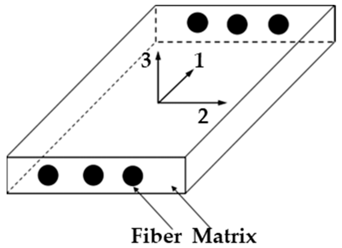
2.4. Elastic Constants of Composite Material
2.5. Overall Stiffness of a Typical Unbonded Flexible Riser
2.6. Compatibility Equation
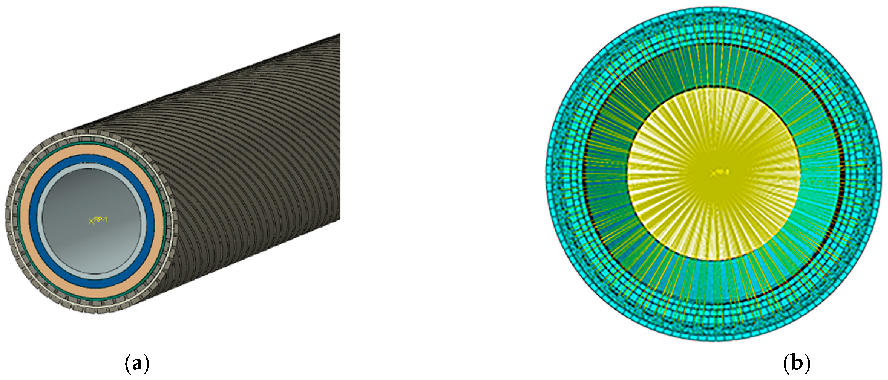
3. Finite Element Model
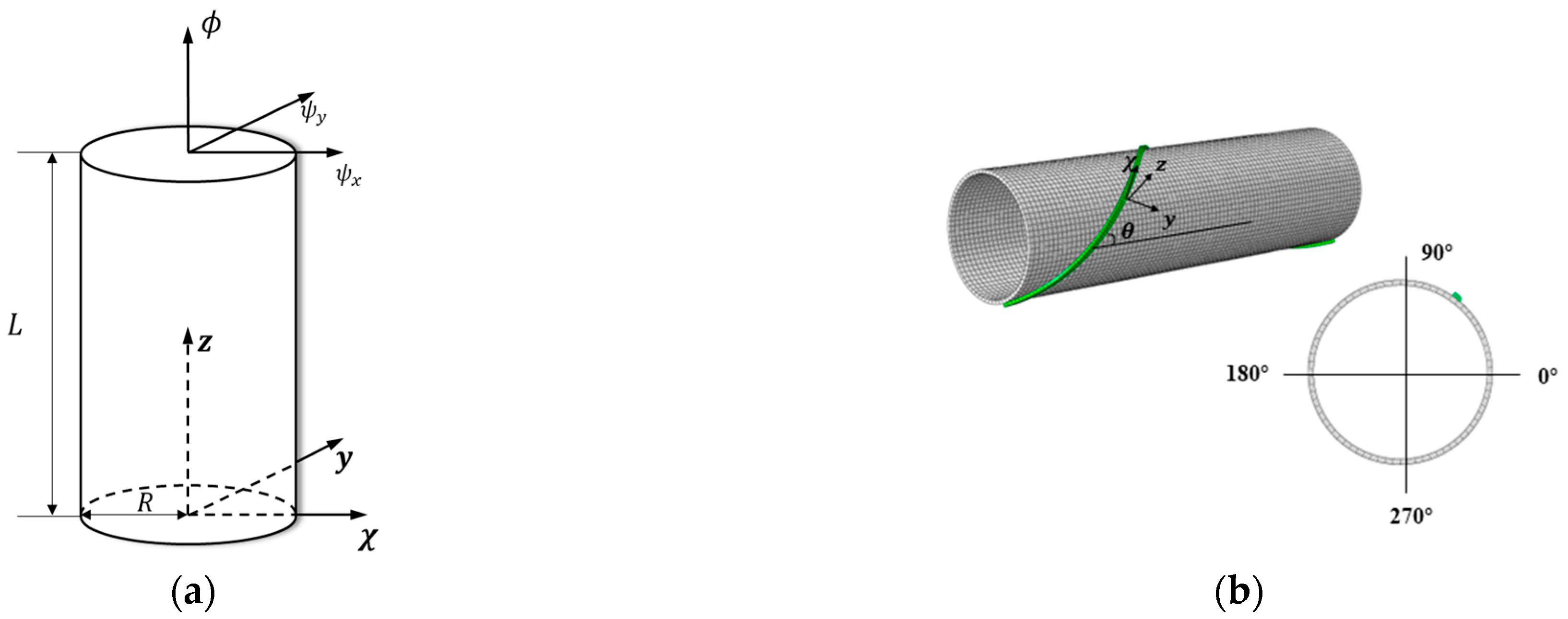
3.1. Geometric and Material Parameters
3.2. Boundary Conditions and Settings
4. Case Study
4.1. Axial Tensile Response
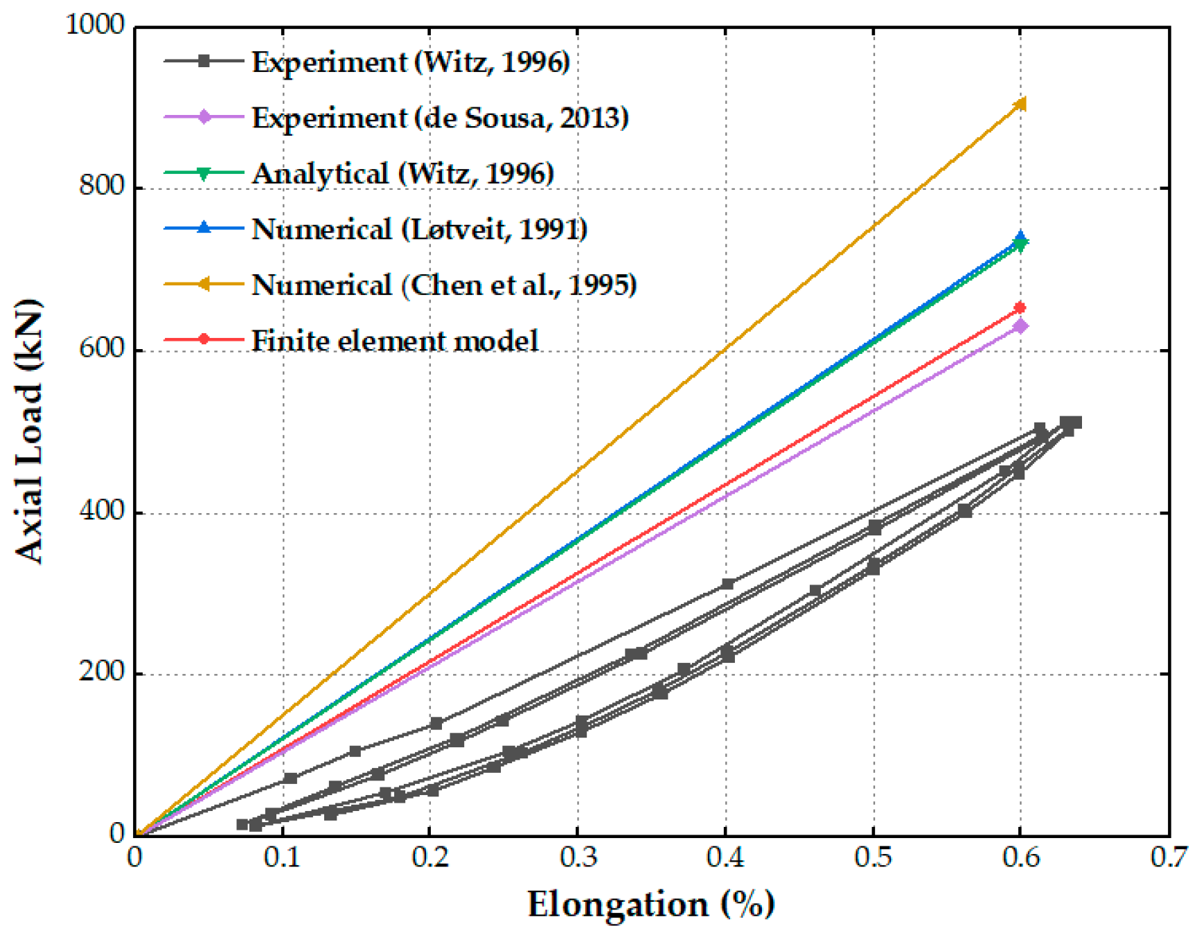
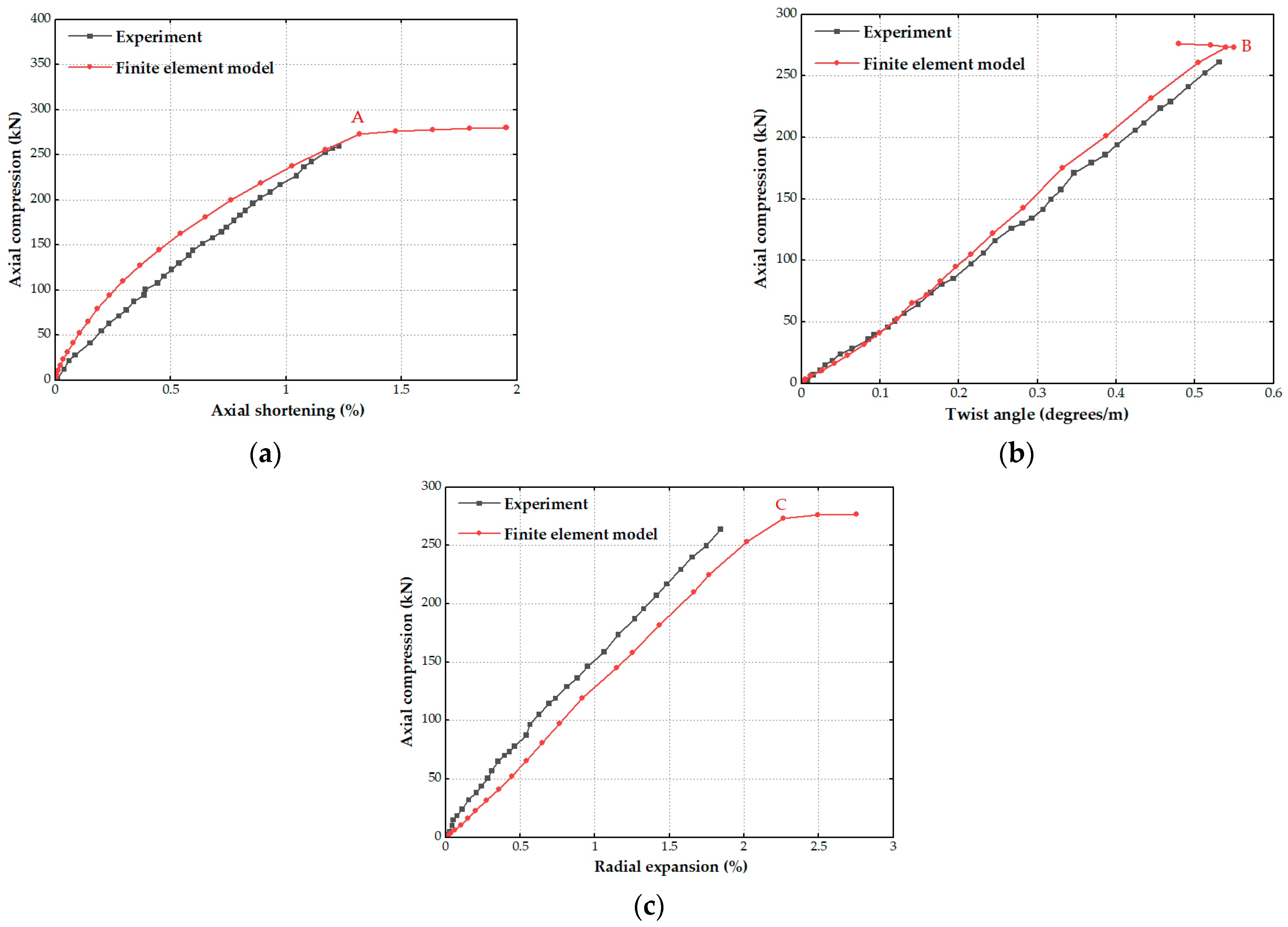
4.1.1. Model Verification
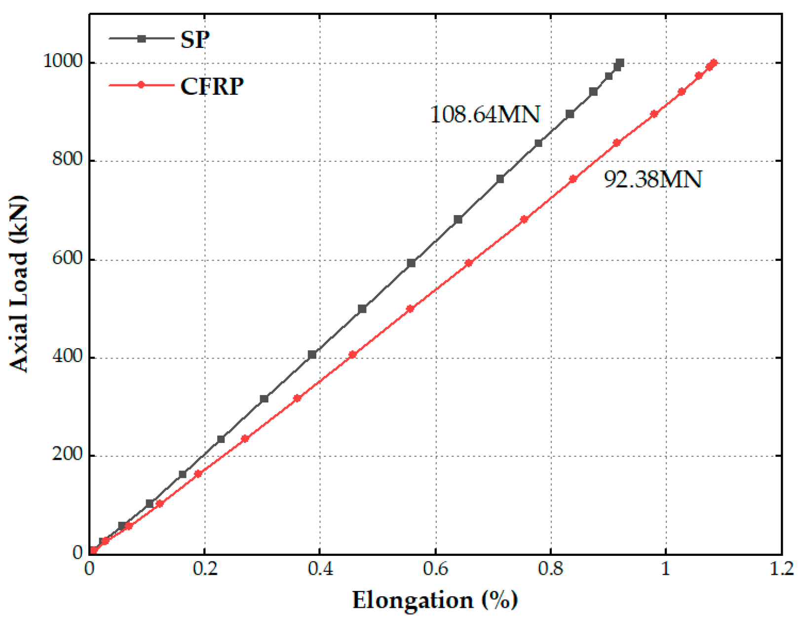
4.1.2. Carbon Fiber Composite Materials Armored Flexible Pipe
4.1.3. Ultimate Tensile Strength
4.1.4. Effect of Coefficient Friction
4.2. Axial Compression Response
4.2.1. Carbon Fiber Composite Materials Armored Flexible Pipe
4.2.2. Effect of Hydrostatic Pressure
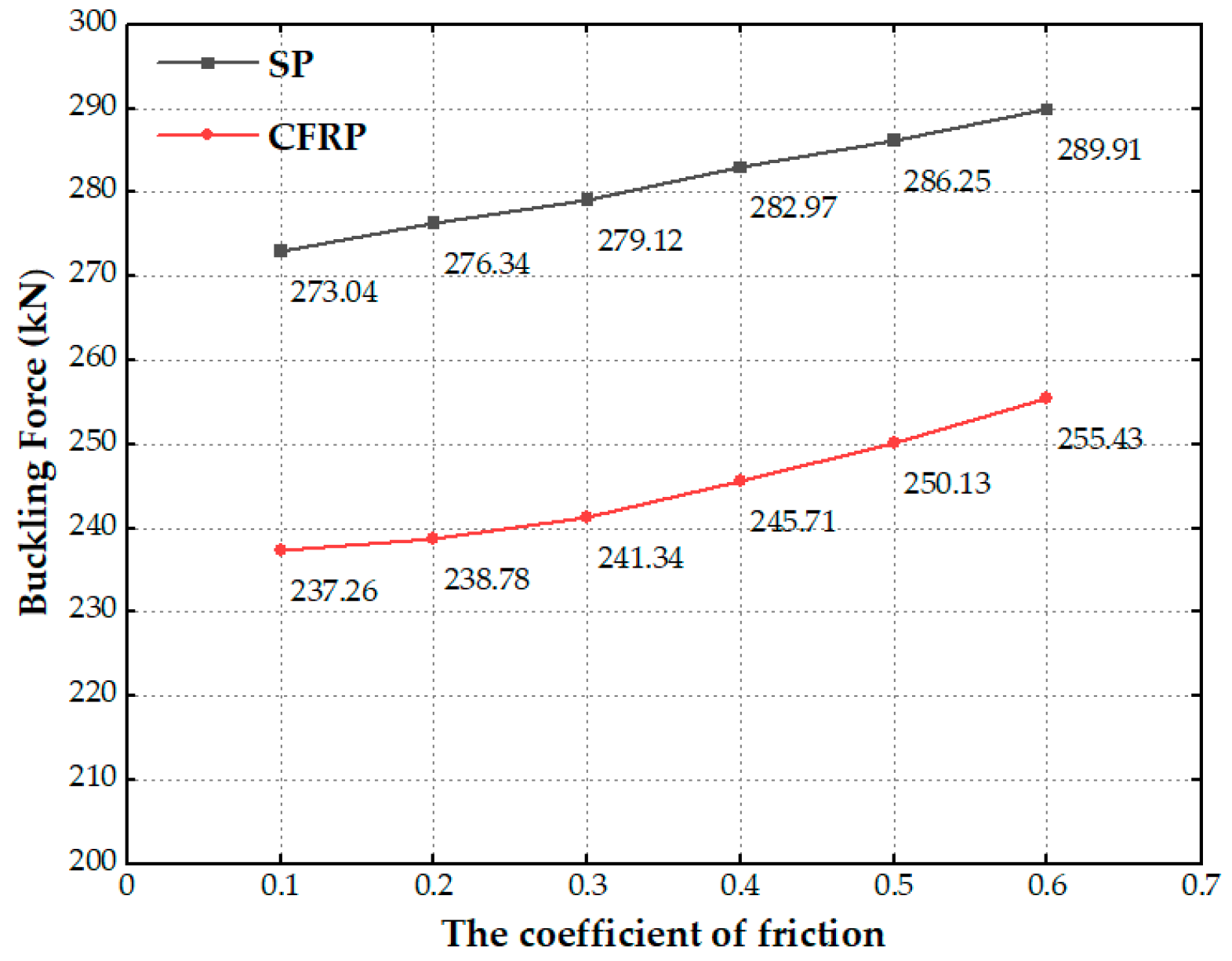
4.2.3. Effect of Coefficient Friction
5. Conclusions
- (1)
- The model proposed in this article demonstrates its effectiveness in predicting the tensile response of the riser. When utilizing carbon fiber composite material to replace steel in the tensile armor of the flexible riser, the tensile stiffness of the pipe experiences a decrease of only 15% while maintaining the same section size. Moreover, the ultimate tensile stiffness of the composite flexible pipe is significantly increased. The substitution of carbon fiber material results in a 77.7% reduction in the weight of the tensile armor layer;
- (2)
- The axial tensile rigidity of the flexible riser remains unaffected by the coefficient of friction between layers. However, the coefficient of friction significantly impacts the compression response of the pipe. An increase in the friction coefficient delays the lateral movement of the tensile armor wires, leading to a gradual increase in the critical buckling load of the flexible riser;
- (3)
- The finite element analysis (FEA) conducted in this study revealed that the failure of the flexible pipe is caused by excessive radial expansion of the tensile armor wires. This type of failure is identified by the rupture of both the high-strength tape and outer sheath layers of the pipe. The consequence is an abrupt reduction in axial stiffness and a rapid increase in radial expansion;
- (4)
- The radial expansion of the tensile armor is constrained as the hydrostatic pressure increases. Due to the lower radial stiffness of the carbon fiber tensile armor layer, the axial stiffness of the composite flexible riser increases more significantly under external pressure. The critical load of the carbon fiber armor layer can reach up to 86.8% of that of the steel armor layer.
Author Contributions
Funding
Institutional Review Board Statement
Informed Consent Statement
Data Availability Statement
Conflicts of Interest
References
- Fetisov, V.; Shalygin, A.V.; Modestova, S.A.; Tyan, V.K.; Shao, C. Development of a Numerical Method for Calculating a Gas Supply System during a Period of Change in Thermal Loads. Energies 2023, 16, 60. [Google Scholar] [CrossRef]
- Fetisov, V.; Gonopolsky, A.M.; Zemenkova, M.Y.; Andrey, S.; Davardoost, H.; Mohammadi, A.H.; Riazi, M. On the Integration of CO2 Capture Technologies for an Oil Refinery. Energies 2023, 16, 865. [Google Scholar] [CrossRef]
- Ilyushin, Y.V.; Fetisov, V. Experience of virtual commissioning of a process control system for the production of high-paraffin oil. Sci. Rep. 2022, 12, 18415. [Google Scholar] [CrossRef]
- Ma, W.; Zhang, K.; Du, Y.; Liu, X.; Shen, Y. Status of Sustainability Development of Deep-Sea Mining Activities. J. Mar. Sci. Eng. 2022, 10, 1508. [Google Scholar] [CrossRef]
- Knapp, R. Derivation of a new stiffness matrix for helically armoured cables considering tension and torsion. Int. J. Numer. Methods Eng. 1979, 14, 515–529. [Google Scholar] [CrossRef]
- Tan, Z.; Loper, C.; Sheldrake, T.; Karabelas, G. Behavior of Tensile Wires in Unbonded Flexible Pipe Under Compression and Design Optimization for Prevention. In Proceedings of the 25th International Conference on Offshore Mechanics and Arctic Engineering, Hamburg, Germany, 4–9 June 2006; pp. 43–50. [Google Scholar]
- Fe’ret, J.J.; Bournazel, C.L. Calculation of Stresses and Slip in Structural Layers of Unbonded Flexible Pipes. J. Offshore Mech. Arct. Eng. 1987, 109, 263–269. [Google Scholar] [CrossRef]
- Chen, B.; Kalman, M.; Lewicki, P.; Zhang, Y. Analytical and finite element modelling of nonbonded flexible pipe structures. In Proceedings of the Marinflex 95, 2nd European Conference on Flexible Pipes, Umbilicals & Marine Cables, London, UK, 20–21 November 1995. [Google Scholar]
- Sævik, S.; Thorsen, M.J. An Analytical Treatment of Buckling and Instability of Tensile Armors in Flexible Pipes. J. Offshore Mech. Arct. Eng. 2017, 139, 041701. [Google Scholar] [CrossRef]
- Chung, J.S.; Felippa, C.A. Nonlinear Static Analysis of Deep Ocean Mining Pipe—Part II: Numerical Studies. J. Energy Resour. Technol. 1981, 103, 16–25. [Google Scholar] [CrossRef]
- Felippa, C.A.; Chung, J. Nonlinear static analysis of deep ocean mining pipe—Part I: Modeling and formulation. J. Energy Resour. Technol. 1981, 103, 11–15. [Google Scholar] [CrossRef]
- Løtveit, S.; Often, O. Increased reliability through a unified analysis tool for bonded and non-bonded pipes. In Advances in Subsea Pipeline Engineering and Technology, Proceedings of the Aspect ’90, Aberdeen, UK, 30–31 May 1990; Springer: Dordrecht, The Netherlands, 1990; pp. 79–110. [Google Scholar]
- Witz, J.A. A case study in the cross-section analysis of flexible risers. Mar. Struct. 1996, 9, 885–904. [Google Scholar] [CrossRef]
- Bectarte, F.; Coutarel, A. Instability of Tensile Armour Layers of Flexible Pipes Under External Pressure. In Proceedings of the ASME 2004 23rd International Conference on Offshore Mechanics and Arctic Engineering, Vancouver, BC, Canada, 20–25 June 2004; pp. 155–161. [Google Scholar]
- Bahtui, A.; Bahai, H.; Alfano, G. A Finite Element Analysis for Unbonded Flexible Risers Under Axial Tension. In Proceedings of the ASME 2008 27th International Conference on Offshore Mechanics and Arctic Engineering, Estoril, Portugal, 15–20 June 2008; pp. 529–534. [Google Scholar]
- Bahtui, A.; Bahai, H.; Alfano, G. Numerical and Analytical Modeling of Unbonded Flexible Risers. J. Offshore Mech. Arct. Eng. 2009, 131, 021401. [Google Scholar] [CrossRef]
- de Sousa, J.R.; Magluta, C.; Roitman, N.; Ellwanger, G.B.; Lima, E.C.; Papaleo, A. On the response of flexible risers to loads imposed by hydraulic collars. Appl. Ocean Res. 2009, 31, 157–170. [Google Scholar] [CrossRef]
- Vaz, M.A.; Rizzo, N.A.S. A finite element model for flexible pipe armor wire instability. Mar. Struct. 2011, 24, 275–291. [Google Scholar] [CrossRef]
- de Sousa, J.R.M.; Viero, P.F.; Magluta, C.; Roitman, N. An Experimental and Numerical Study on the Axial Compression Response of Flexible Pipes. J. Offshore Mech. Arct. Eng. 2012, 134, 031703. [Google Scholar] [CrossRef]
- de Sousa, J.R.M.; Magluta, C.; Roitman, N.; Londoño, T.V.; Campello, G.C. A Study on the Response of a Flexible Pipe to Combined Axisymmetric Loads. In Proceedings of the ASME 2013 32nd International Conference on Ocean, Offshore and Arctic Engineering, Nantes, France, 9–14 June 2013. [Google Scholar]
- Saevik, S.; Berge, S. Fatigue testing and theoretical studies of two 4 in flexible pipes. Eng. Struct. 1995, 17, 276–292. [Google Scholar] [CrossRef]
- Sævik, S. Theoretical and experimental studies of stresses in flexible pipes. Comput. Struct. 2011, 89, 2273–2291. [Google Scholar] [CrossRef]
- Chethan, K.; Bhat, N.S.; Zuber, M.; Shenoy, B.S. Finite element analysis of hip implant with varying in taper neck lengths under static loading conditions. Comput. Methods Programs Biomed. 2021, 208, 106273. [Google Scholar] [CrossRef] [PubMed]
- Do, A.T.; Lambert, A. Qualification of Unbonded Dynamic Flexible Riser with Carbon Fibre Composite Armors. In Proceedings of the Offshore Technology Conference, Rio de Janeiro, Brazil, 1–6 July 2012. [Google Scholar]
- Amaechi, C.V.; Gillett, N.; Odijie, A.C.; Hou, X.; Ye, J. Composite risers for deep waters using a numerical modelling approach. Compos. Struct. 2019, 210, 486–499. [Google Scholar] [CrossRef] [Green Version]
- Amaechi, C.V.; Chesterton, C.; Butler, H.O.; Gillet, N.; Wang, C.; Ja’e, I.A.; Reda, A.; Odijie, A.C. Review of Composite Marine Risers for Deep-Water Applications: Design, Development and Mechanics. J. Compos. Sci. 2022, 6, 96. [Google Scholar] [CrossRef]
- Sparks, C.P.; Odru, P.; Bono, H.; Metivaud, G. Mechanical Testing Of High-Performance Composite Tubes For Tlp Production Risers. In Proceedings of the Offshore Technology Conference, Houston, TX, USA, 2–5 May 1988. [Google Scholar]
- Beyle, A.; Gustafson, C.; Kulakov, V.; Tarnopol’skii, Y.M. Composite risers for deep-water offshore technology: Problems and prospects. 1. Metal-composite riser. Mech. Compos. Mater. 1997, 33, 403–414. [Google Scholar] [CrossRef]
- Lotveit, S.A.; Ward, H.L. Fibre Reinforced Flexible Pipe Material Selection And Design Methods. In Proceedings of the The First International Offshore and Polar Engineering Conference, Edinburgh, UK, 11–16 August 1991. [Google Scholar]
- Baldwin, D.D.; Newhouse, N.L.; Lo, K.H.; Burden, R.C. Composite Production Riser Design. In Proceedings of the Offshore Technology Conference, Houston, TX, USA, 5–8 May 1997. [Google Scholar]
- Baldwin, D.D.; Lo, K.H.; Long, J.R. Design Verification of a Composite Production Riser. In Proceedings of the Offshore Technology Conference, Houston, TX, USA, 4–7 May 1998. [Google Scholar]
- Salama, M.M.; Johnson, D.B.; Long, J.R. Composite Production Riser—Testing and Qualification. SPE Prod. Facil. 1998, 13, 170–177. [Google Scholar] [CrossRef]
- Andersen, W.; Anderson, J.; Mickelson, C.; Sweeney, T. The application of advanced composite technology to marine drilling riser systems: Design, manufacturinagn d test. In Proceedings of the Offshore Technology Conference, Houston, TX, USA, 5–8 May 1997. [Google Scholar]
- Johnson, D.B.; Baldwin, D.D.; Long, J.R. Mechanical performance of composite production risers. In Proceedings of the Offshore Technology Conference, Houston, TX, USA, 3–6 May 1999. [Google Scholar]
- Johnson, D.B.; Baldwin, D.D.; Lo, K.H. Composite production riser development and qualification test results. In Proceedings of the Third International Conference on Composite Materials for Offshore Operations, Houston, TX, USA, 31 October–2 November 2000. [Google Scholar]
- Kalman, M.; Loper, C. Development of composite-armored flex risers for deep water. World Oil 1998, 219, 103–106. [Google Scholar]
- Salama, M.M.; Stjern, G.; Storhaug, T.; Spencer, B.; Echtermeyer, A. The First Offshore Field Installation for a Composite Riser Joint. In Proceedings of the Offshore Technology Conference, Houston, TX, USA, 6–9 May 2002. [Google Scholar]
- Ochoa, O.O.; Salama, M.M. Offshore composites: Transition barriers to an enabling technology. J. Compos. Sci. Technol. 2005, 65, 2588–2596. [Google Scholar] [CrossRef]
- DNV-RP-F202; Composite Risers. Det Norske Veritas: Høvik, Norway, 2009.
- Ochoa, O. Composite Riser Experience and Design Guidance; MMS Project Number 490; Offshore Technology Research Center: College Station, TX, USA; Austin, TX, USA, 2006. [Google Scholar]
- Ramirez, G.; Engelhardt, M.D. Experimental Investigation of a Large-Scale Composite Riser Tube Under External Pressure. J. Press. Vessel Technol. 2009, 131, 051205. [Google Scholar] [CrossRef]
- Almeida, J.H.S., Jr.; Ribeiro, M.L.; Tita, V.; Amico, S.C. Damage and failure in carbon/epoxy filament wound composite tubes under external pressure: Experimental and numerical approaches. Mater. Des. 2016, 96, 431–438. [Google Scholar] [CrossRef]
- Almeida, J.H.S., Jr.; Ribeiro, M.L.; Tita, V.; Amico, S.C. Stacking sequence optimization in composite tubes under internal pressure based on genetic algorithm accounting for progressive damage. Compos. Struct. 2017, 178, 20–26. [Google Scholar] [CrossRef]
- Toh, W.; Tan, L.B.; Jaiman, R.K.; Tay, T.E.; Tan, V.B.C. A comprehensive study on composite risers: Material solution, local end fitting design and global response. Mar. Struct. 2018, 61, 155–169. [Google Scholar] [CrossRef]
- Zhang, H.; Tong, L.; Addo, M.A. Mechanical Analysis of Flexible Riser with Carbon Fiber Composite Tension Armor. J. Compos. Sci. 2021, 5, 3. [Google Scholar] [CrossRef]
- Halpin, J.; Tsai, S. Environmental Factors in Composite Materials Design; Air Force Technical Report AFML-TR 67-423; Wright Aeronautical Laboratories: Dayton, OH, USA, 1967. [Google Scholar]
- Tawfik, S.; Tan, X.; Ozbay, S.; Armanios, E. Anticlastic Stability Modeling for Cross-ply Composites. J. Compos. Mater. 2007, 41, 1325–1338. [Google Scholar] [CrossRef]
- Yoo, D.-H.; Jang, B.-S.; Yim, K.-H. Nonlinear finite element analysis of failure modes and ultimate strength of flexible pipes. Mar. Struct. 2017, 54, 50–72. [Google Scholar] [CrossRef]







| Layer | Internal Radius (mm) | External Radius (mm) | External Radius (mm) | Thickness (mm) | Laying Angle | Number | Material |
|---|---|---|---|---|---|---|---|
| Carcass | 31.6 | 35.1 | 35.1 | 3.5 | 87.5° | - | AISI304 |
| Inner sheath | 35.1 | 40.05 | 40.05 | 5 | - | - | Nylon 12 |
| Pressure armor | 40.05 | 46.25 | 46.25 | 6.2 | 85.5° | - | F115 |
| Anti-wear tap | 46.25 | 47.75 | 47.75 | 1.5 | - | - | Nylon 11 |
| Inner tensile armor | 47.75 | 50.75 | 50.75 | 3 | 35° | 40 | F141/T300 |
| Anti-wear tap | 50.75 | 52.25 | 52.25 | 1.5 | - | - | Nylon 11 |
| Outer tensile armor | 52.25 | 55.25 | 55.25 | 4 | -35° | 44 | F141/T300 |
| Outer Sheath | 55.25 | 55.75 | 55.75 | 0.5 | - | - | Polymer |
| Materials | E (MPa) | υ | Density (kg∙m−3) |
|---|---|---|---|
| AISI304 | 199 | 0.3 | 7930 |
| Nylon 12 | 0.284 | 0.3 | 1080 |
| F115 | 0.301 | 0.3 | 1040 |
| Nylon 11 | 207 | 0.3 | 7850 |
| F141 | 211 | 0.3 | 7870 |
| Polymer | 0.6 | 0.3 | 800 |
| E1 | E2 | E3 | G12 | G13 | G23 | |||
|---|---|---|---|---|---|---|---|---|
| 181,000 MPa | 10,300 MPa | 10,300 MPa | 0.28 | 0.3 | 0.28 | 7170 MPa | 7170 MPa | 3780 MPa |
| Scholar | (MN) | References |
|---|---|---|
| Witz | 91.19 | Experiment (Witz, 1996) [38] |
| de Sousa | 105.1 | Experiment (de Sousa, 2012) [37] |
| Witz | 123.33 | Analytical (Witz, 1996) [38] |
| Seaflex | 122 | Numerical (Løtveit, 1991) [39] |
| Wellstream | 151 | Numerical (Chen et al., 1995) [40] |
| 108.64 | Finite element model (This article) |
| Layer | Material Type | Properties | Element Type |
|---|---|---|---|
| Carcass | Stainless steel | t = 4.0 mm; E = 193 GPa; v = 0.3 | C3D8I |
| Inner sheath | Polyamide 11 | t = 5.0 mm; E = 345 MPa; v = 0.3 | C3D8I |
| Pressure armor | Carbon steel | t = 6.2 mm; E= 205 GPa; v = 0.3 | C3D8I |
| Tensile armor 1 | CFRP(T300) | t = 2 mm; Lay angle = 35° | C3D8I |
| Tensile armor 2 | CFRP(T300) | t = 2 mm; Lay angle = −35° | C3D8I |
| High strength tape | Aramid fiber | t = 1.2 mm; v = 0.3 | C3D8I |
| Outer sheath | Polyamide 11 | t = 2 mm; E = 345 MPa; v = 0.3 | C3D8I |
| Buckling Force (kN) | Axial Strain (%) | Twist Angle (deg/m) | |
|---|---|---|---|
| Experiment (de Sousa) | 263 | 1.21 | 0.53 |
| Finite element model | 273.04 | 1.31 | 0.55 |
| Difference | 3.82% | 8.26% | 3.77% |
Disclaimer/Publisher’s Note: The statements, opinions and data contained in all publications are solely those of the individual author(s) and contributor(s) and not of MDPI and/or the editor(s). MDPI and/or the editor(s) disclaim responsibility for any injury to people or property resulting from any ideas, methods, instructions or products referred to in the content. |
© 2023 by the authors. Licensee MDPI, Basel, Switzerland. This article is an open access article distributed under the terms and conditions of the Creative Commons Attribution (CC BY) license (https://creativecommons.org/licenses/by/4.0/).
Share and Cite
Liu, H.; Li, M.; Shen, Y. Numerical Analysis of Mechanical Behaviors of Composite Tensile Armored Flexible Risers in Deep-Sea Oil and Gas. J. Mar. Sci. Eng. 2023, 11, 619. https://doi.org/10.3390/jmse11030619
Liu H, Li M, Shen Y. Numerical Analysis of Mechanical Behaviors of Composite Tensile Armored Flexible Risers in Deep-Sea Oil and Gas. Journal of Marine Science and Engineering. 2023; 11(3):619. https://doi.org/10.3390/jmse11030619
Chicago/Turabian StyleLiu, Hu, Meng Li, and Yijun Shen. 2023. "Numerical Analysis of Mechanical Behaviors of Composite Tensile Armored Flexible Risers in Deep-Sea Oil and Gas" Journal of Marine Science and Engineering 11, no. 3: 619. https://doi.org/10.3390/jmse11030619
APA StyleLiu, H., Li, M., & Shen, Y. (2023). Numerical Analysis of Mechanical Behaviors of Composite Tensile Armored Flexible Risers in Deep-Sea Oil and Gas. Journal of Marine Science and Engineering, 11(3), 619. https://doi.org/10.3390/jmse11030619


