Article

Natural Frequency Analysis of Monopile Supported Offshore Wind Turbines Using Unified Beam-Column Element Model

1
School of Civil Engineering, Sun Yat-Sen University & Southern Marine Science and Engineering Guangdong Laboratory (Zhuhai), Zhuhai 519082, China
2
Department of Civil and Environmental Engineering, Hong Kong Polytechnic University, Hong Kong 999077, China
*
Author to whom correspondence should be addressed.
J. Mar. Sci. Eng. 2023, 11(3), 628; https://doi.org/10.3390/jmse11030628
Submission received: 7 February 2023 / Revised: 11 March 2023 / Accepted: 14 March 2023 / Published: 16 March 2023

Abstract

:
Assessment of the natural frequency of the offshore wind turbine (OWT) system is a critical task in design to avoid resonance. The natural frequency of the monopile supported OWT may change during operation and needs to be calculated regularly. Conventional numerical methods separately model different components of the OWT system using various element types, which require tedious data manipulations and are inefficient to assess the changing natural frequency of the monopile supported OWTs. This paper develops a unified beam-column element by directly integrating the soil-pile interactions in element formulation. The proposed method is applicable for different components of the OWT system, including the rotor, the tower, the transition piece, and the monopile foundation, which enables an integrated and efficient OWT analysis by using only one type of element. The pile-soil interactions are directly considered in the element formulation. The tedious soil spring elements are avoided. Definitions and formulations of the proposed element are provided and the numerical solution procedure for the natural frequency analysis of OWTs is illustrated. The accuracy of the proposed element is validated against several closed-form solutions and the distributed spring model. The proposed method is also applied to analyze the natural frequencies of six OWTs in practice. The calculated results are consistent with the field measured data.

1. Introduction

Offshore wind turbines (OWTs) receive increasing attentions for their ability to capture massive wind resources [1,2,3,4,5]. Over 80% of OWTs in shallow sea are supported by monopile foundation [6] (Figure 1a), which are mainly made of structural steel. For the steel monopile supported OWT, the natural frequency is a critical design parameter as it is subjected to complicated dynamic loads such as wind and wave during its life cycle. In some cases, the design of OWTs is even controlled by the natural frequency instead of the strength and serviceability [7].
The natural frequency of the OWT system must not overlap with the excitation frequencies, such as wind frequency, wave frequency, rotational frequency of the rotor (1P), and blade passing frequency of the three-bladed wind turbine (3P) to avoid resonance and extensive fatigue damage [8,9]. As shown in Figure 2, there are three ranges, named soft-soft, soft–stiff, and stiff–stiff, around the excitation frequencies during the design process [10]. The soft–stiff range is most commonly used to design the wind turbine structure due to the cost effectiveness. However, the soft-stiff range is very limited, especially for the variable-speed wind turbine.
The stiffness of the OTW may change significantly during its lifetime due to seabed scour, which could alter the pile embedment depth and reduce the structural stiffness, resulting in the variation of the natural frequency [11,12]. Undesirable consequences can be caused if the natural frequency exceeds the soft–stiff range. Therefore, it is required to assess the natural frequency of the OWT system regularly during operation to ensure that the frequency variation lays within the adequate margin of the soft–stiff range. Moreover, the assessment method should be convenient and efficient so that potential risks can be identified in time.
Fei et al. [13] developed a finite element model to calculate the natural frequency of an OWT assuming a fixed base. Tempel [14] presented an approximate solution for the first natural frequency using the simplified model consisting of a uniform cantilever beam with a top lumped mass and a fixed base. However, the fixed base model overestimates the natural frequency of monopile supported OWTs by 4–15% because it will overestimate the soil constraint effect [15,16]. Therefore, it is essential to integrally consider the pile-soil interaction in the frequency analysis of the OWT system.
Two types of numerical analysis models are commonly used to analyze the natural frequency of the monopile supported OWTs considering the pile-soil interaction, which are the equivalent coupled springs model [15,17,18,19,20,21] and the distributed spring model [22,23,24,25,26,27]. Williams et al. [28] developed a modified distributed spring model considering the ratcheting effect due to long-term dynamic cyclic loading. Sunday and Brennan [29] presented the 3D finite element modelling of monopile connected with the distributed soil springs along the pile length to study the structural response. As shown in Figure 1, The equivalent coupled springs model and distributed spring model use various element types to separately model different components of the OWT system due to their differences in geometric and material properties. For example, the tapered circular hollow tower is modeled by stepped beam elements, while the monopile and its surrounding soil are modeled by beam element with a set of soil spring elements connected to the beam element nodes. The complexity in modelling leads to a lack in flexibility, making it difficult to model the changing pile embedment depth and the structural stiffness in time. Moreover, the pile-soil interactions are modelled by distributed spring elements. It is required to utilize enough soil springs to accurately capture the nonlinear variations of soil stiffness along the pile depths [30,31,32]. This results in tedious data manipulations because geometric and material parameters need to be defined for a large number of elements. The same is true for the modelling of the tapered tower by the stepped element to consider its axial and flexural rigidity, which also requires a large number of elements to ensure a sufficient approximation accuracy [33,34,35]. Recently, Wan et al. [36] proposed a non-prismatic beam-column element model to investigate the buckling response of tapered piles, which can effectively consider the nonlinear pile-soil interactions. However, this method only focuses on pile buckling responses and cannot be applied to the natural frequency analysis of OWTs. Therefore, it is necessary to develop a unified element to conveniently and accurately simulate different components of the OWT system considering pile-soil interactions.
This study aims to present a unified beam-column element to assess the natural frequency of the monopile supported OWT. The proposed element is applicable for different components of the OWT system, including the rotor, the tower, the transition piece, and the monopile foundation, which enables an integrated and efficient OWT analysis. The pile-soil interactions are directly considered in the element formulation. The tedious soil spring elements are avoided. Definitions and formulations of the proposed element are provided and the numerical solution procedure for the natural frequency analysis of OWTs is illustrated. The obtained results by the proposed method are compared with closed-form solutions, distributed spring model, and field measurements to validate the accuracy of the proposed method.

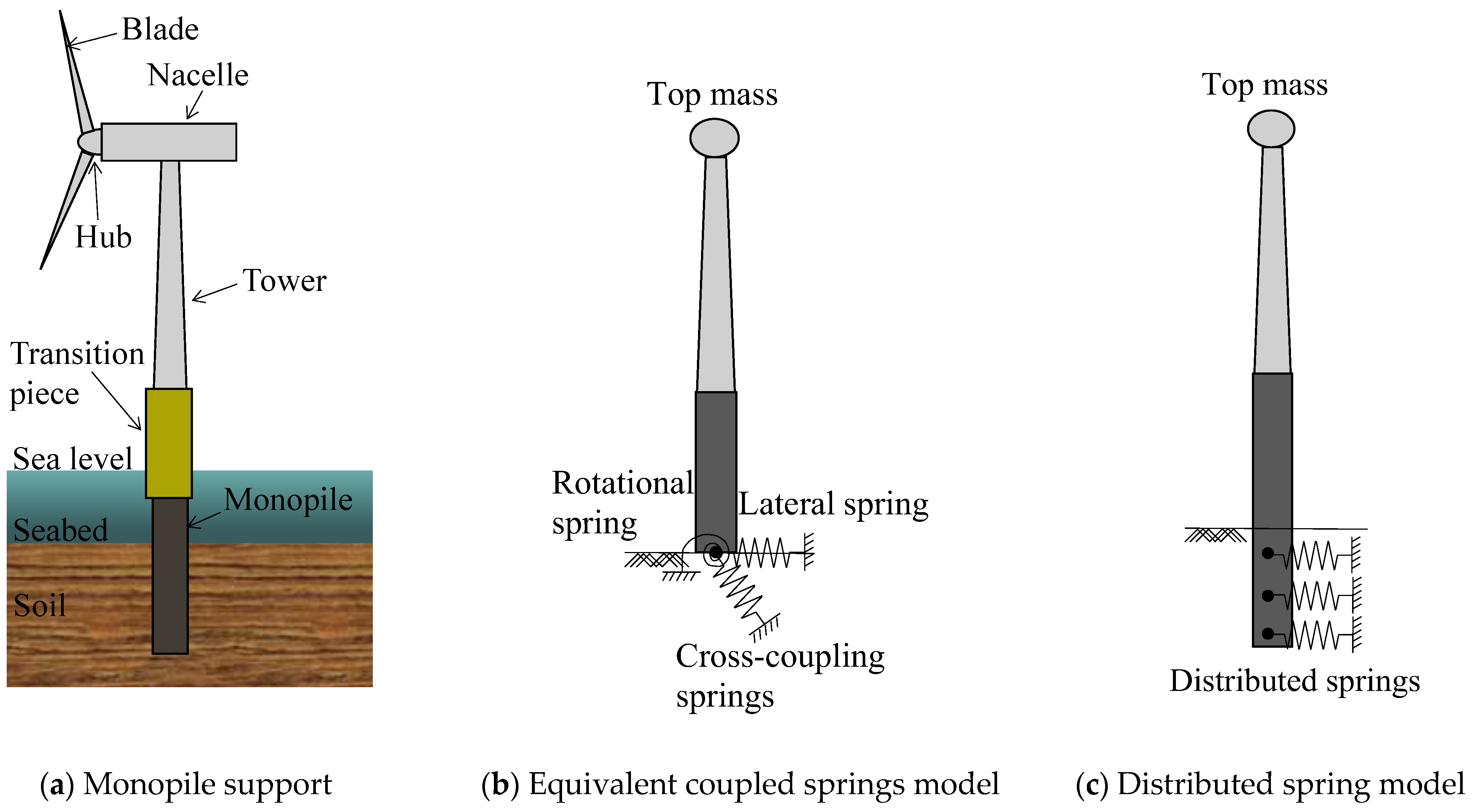
2. Structural Model of the OWT

A unified beam-column element was developed which consisted of the structural element and the internal zero-length soil springs. The proposed element was characterized by the following features:
(1) It is efficient to consider the variations of soil resistance within the element by using zero-length soil springs. Different from the spring elements in the distributed spring model, the zero-length soil springs are directly incorporated into the element formulation by the Gauss–Legendre integration method [37], which is straightforward in terms of data manipulation because there is no need to determine the stiffness for each soil spring, and it eliminates the revision to the spring properties when changing the element sizes.
(2) The structural element is able to simulate different section types by changing its geometry, including hollow circular, solid circular, and tapered hollow circular sections. The analytical expressions of the axial and flexural rigidity and distributed mass of prismatic and tapered cross-sections are adopted to reflect the element stiffness and self-weight variation. The variation of pile embedment and structural stiffness during the OWT operation can be easily modeled by the proposed element without tedious data manipulations.
(3) It is flexible to model different components of OWT by transforming the proposed element into several shapes. As shown in Figure 3, for the modelling of the pile-soil system, the internal soil springs will be activated, and the unified element will be transformed into the shape of element j (considering the pile and its surrounding soil). For the modelling of the tower and transition piece, the unified element is transformed into the specific shape of the section type based on the input parameters of the cross-section (e.g., element i for the tapered hollow circular section). The total mass of the rotor and blades can also be taken into account by using one unified element on the top (i.e., element m).
Reasonable simplifications were required in structural modelling. This proposed element was developed on the basis of the following assumptions:
(1) The Euler–Bernoulli assumption is adopted in the proposed element derivation. The Timoshenko assumption considering shear deformation does not improve the results significantly when calculating the natural frequencies [18].
(2) The material of the OWT is assumed to be isotropic, elastic, and homogeneous.
(3) The influence of the seawater, damping, and the door opening at the tower base are not considered.
(4) The tower has a linearly variable cross-section along its length.
(5) Only the mass of rotor and blades is considered at the top of the wind turbine.

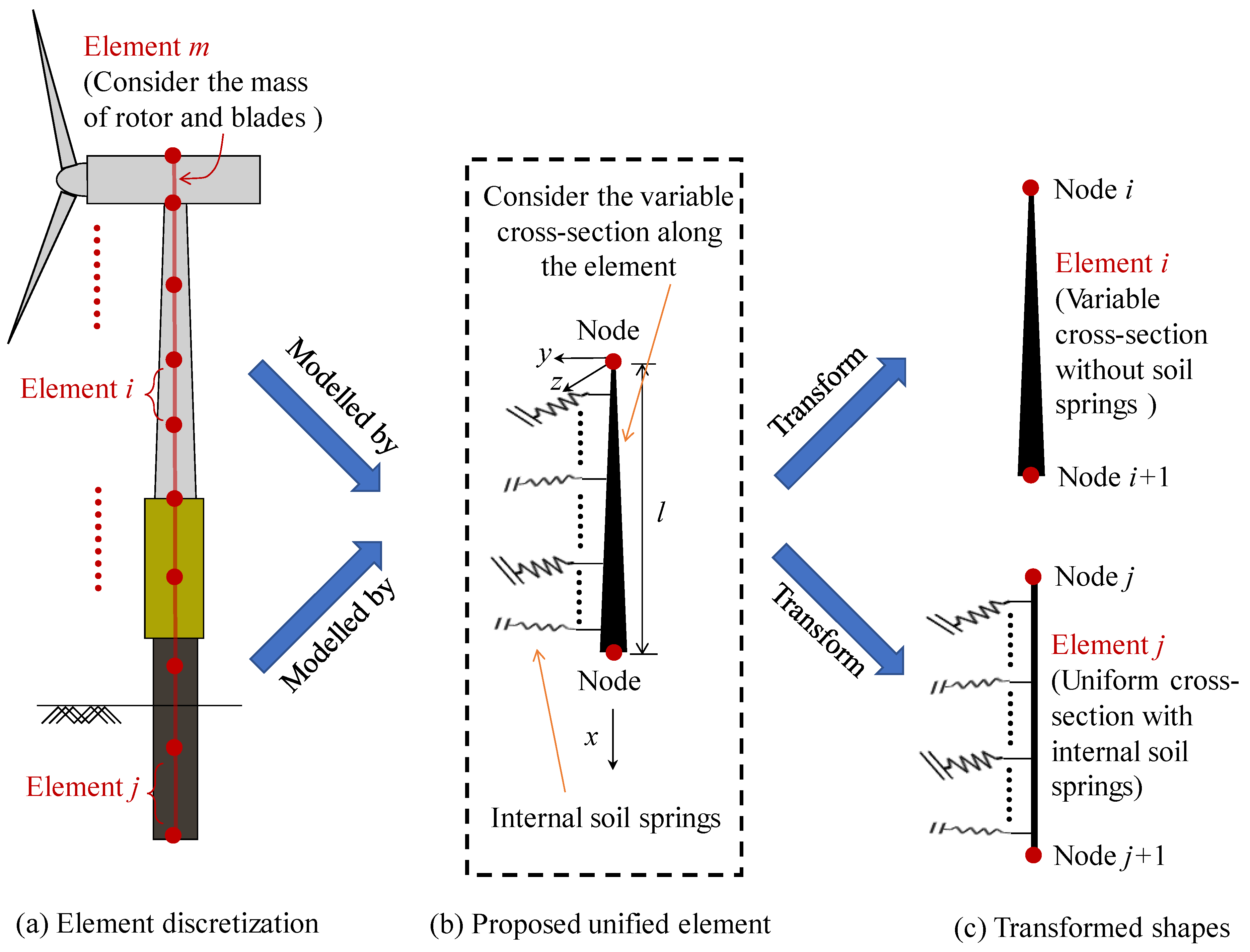
3. Element Formulations

3.1. Tangent Stiffness Matrix

Figure 3 shows the proposed 3D unified beam-column element. The element has a length of l and contains six degrees of freedom at each node. The diameter D(x) is assumed to be linearly varied along the element length, and the mathematical expressions are given below:
D ( x ) = D ( x i ) + ( D ( x i + 1 ) D ( x i ) ) x l
where xi is the coordinate of the x-axis at the ith node, and D(xi) and D(xi+1) are the diameters at the element node i and i + 1, which can be transformed to the actual dimensions of the different wind turbine components.
For hollow circular sections with thickness tw, the moment of inertia about the y- and z-axes and the cross-sectional area at x position are, respectively, given by
I y ( x ) = I z ( x ) = π [ D 4 ( x ) ( D ( x ) 2 t w ) 4 ] 64
A ( x ) = π [ D 2 ( x ) ( D ( x ) 2 t w ) 2 ] 4
where Iy and Iz are the moments of inertia about the y and z-axes, and A is the cross-sectional area.
The element tangent stiffness is obtained based on the minimum potential energy principle [38], which can be calculated by second variation of the total potential energy and given by:
[ k E ] = [ ψ ] [ k L ] [ ψ ] T + [ k S ]
where [kL] is the linear stiffness matrices; [kS] is the soil stiffness matrix for representing the lateral restraint from soils and will be introduced in next section, and [ψ] is the transformation matrix:
[ ψ ] = [ 1 0 0 0 0 0 0 0 1 / l 0 0 1 / l 0 1 / l 0 0 1 / l 0 0 0 0 1 0 0 0 1 0 0 0 0 0 0 1 0 0 0 1 0 0 0 0 0 0 0 1 / l 0 0 1 / l 0 1 / l 0 0 1 / l 0 0 0 0 1 0 0 0 0 0 0 1 0 0 0 0 0 0 1 ]
The linear stiffness matric [kL] is given by
[ k L ] =   ( α 1 0 0 0 0 0 0 α 2 0 0 α 3 0 0 0 α 2 0 0 α 3 0 0 0 0 0 0 0 α 3 0 0 α 4 0 0 0 α 3 0 0 α 4 )
where
α 1 = E π t w 2 l ( D ( x i ) + D ( x i + 1 ) 2 t w )
α 2 = E π t w 40 l [ 11 D 3 ( x i ) + 5 D 2 ( x i ) D ( x i + 1 ) + 2 D ( x i ) D 2 ( x i + 1 ) + 2 D 3 ( x i + 1 ) 2 ( 19 D 2 ( x i ) + 7 D ( x i ) D ( x i + 1 ) + 4 D 2 ( x i + 1 ) ) t w + 20 ( 3 D ( x i ) + D ( x i + 1 ) ) t w 2 40 t w 3 ]
α 3 = E π t w 40 l ( D ( x i ) + D ( x i + 1 ) 2 t w ) [ 4 D 2 ( x i ) 3 D ( x i ) D ( x i + 1 ) + 4 D 2 ( x i + 1 ) 5 ( D ( x i ) + D ( x i + 1 ) ) t w + 10 t w 2 ]
α 4 = E π t w 40 l [ 2 D 3 ( x i ) + 2 D 2 ( x i ) D ( x i + 1 ) + 5 D ( x i ) D 2 ( x i + 1 ) + 11 D 3 ( x i + 1 ) 2 ( 4 D 2 ( x i ) + 7 D ( x i ) D ( x i + 1 ) + 19 D 2 ( x i + 1 ) ) t w + 20 ( D ( x i ) + 3 D ( x i + 1 ) ) t w 2 40 t w 3 ]
The dynamic analysis using the consistent mass matrix gives better approximations to the exact solution than the lumped mass method for the same element discretization [39]. In this study, the consistent mass matrix for the unified beam-column element is developed and written as
[ m ] = ρ [ β 1 0 0 0 0 0 β 2 0 0 0 0 0 β 3 0 0 0 β 4 0 β 5 0 0 0 β 6 β 3 0 β 4 0 0 0 β 5 0 β 6 0 0 0 0 0 0 0 0 0 0 β 7 0 0 0 β 8 0 β 9 0 β 7 0 β 8 0 0 0 β 9 β 10 0 0 0 0 0 S . β 11 0 0 0 β 12 Y . β 11 0 β 12 0 M . 0 0 0 β 13 0 β 13 ]
where ρ is the material density; and,
β 1 = l π t w ( 3 D ( x i ) + D ( x i + 1 ) 4 t w ) 12
β 2 = l π t w ( D ( x i ) + D ( x i + 1 ) 2 t w ) 12
β 3 = l π t w ( 10 D ( x i ) + 3 D ( x i + 1 ) 13 t w ) 35
β 4   =   l 2 π t w ( 15 D ( x i ) + 7 D ( x i + 1 ) 22 t w ) 420
β 5 = 9 l π t w ( D ( x i ) + D ( x i + 1 ) 2 t w ) 140
β 6 = l 2 π t w ( 7 D ( x i ) + 6 D ( x i + 1 ) 13 t w ) 420
β 7 = l 3 π t w ( 5 D ( x i ) + 3 D ( x i + 1 ) 8 t w ) 840
β 8 = l 2 π t w ( 6 D ( x i ) + 7 D ( x i + 1 ) 13 t w ) 420
β 9 = l 3 π t w ( D ( x i ) + D ( x i + 1 ) 2 t w ) 280
β 10 = l π t w ( D ( x i ) + 3 D ( x i + 1 ) 4 t w ) 12
β 11 = l π t w ( 3 D ( x i ) + 10 D ( x i + 1 ) 13 t w ) 35
β 12 = l 2 π t w ( 7 D ( x i ) + 15 D ( x i + 1 ) 22 t w ) 420
β 13 = l 3 π t w ( 3 D ( x i ) + 5 D ( x i + 1 ) 8 t w ) 840

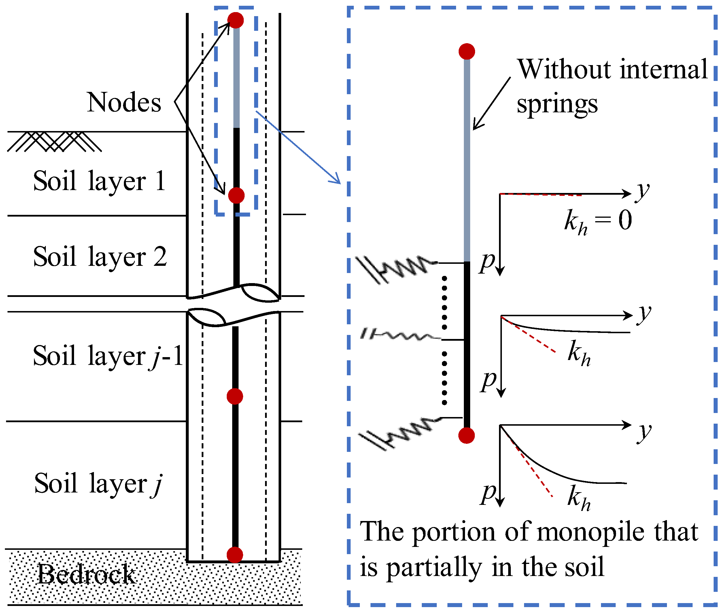
3.2. Internal Zero-Length Soil Springs

As shown in Figure 4, the pile-soil interactions were modeled by proposed elements, which considered the distribution of soil stiffness varied nonlinearly according to the ground medium types. The total soil resistance p can be expressed as a function of the lateral deflection y of the monopile. The ultimate soil resistance was reached when the lateral deflection was at a certain level. The variation in initial p-y stiffness calculated by tangential values at the origin is also shown in Figure 4 with different soil depths. Current design practices, such as DNV-OS-J101 [40], suggest that the initial p-y stiffness (modulus of horizontal subgrade reaction) representing the actual physics of the pile-soil interaction were applied to assess the natural frequency of the OWT system. An accurate estimation of the modulus of horizontal subgrade reaction was required for calculating the lateral response of monopile using the p-y curve [41,42]. In order to meet the requirements of the practical application using the various p-y curves or modulus of horizontal subgrade reaction formulas, the Gauss–Legendre integration method [37] was employed for obtaining the soil stiffness matrix. Therefore, the continuous soil-pile interactions along the pile length could be easily simulated by the proposed element. The soil stiffness matrix [kS] in the form of Gauss–Legendre integration is given by
[ k S ] = [ 0 0 0 0 0 0 0 0 0 0 0 0 χ 1 l 0 0 0 χ 2 l 2 0 χ 3 l 0 0 0 χ 4 l 2 χ 5 l 0 χ 6 l 2 0 0 0 χ 7 l 0 χ 8 l 2 0 0 0 0 0 0 0 0 0 0 χ 9 l 3 0 0 0 χ 10 l 2 0 χ 11 l 3 0 χ 12 l 3 0 χ 13 l 2 0 0 0 χ 14 l 3 0 0 0 0 0 0 S . χ 15 l 0 0 0 χ 16 l 2 Y . χ 17 l 0 χ 18 l 2 0 M . 0 0 0 χ 19 l 3 0 χ 20 l 3 ]
where the values of χ1 to χ20 can be obtained by
χ q = j = 1 n ξ q , j κ j ( q = 1   to   20 )
where ξq,j is the integration parameter which can be found in reference [43]; κj is the tangent values on the soil resistance versus lateral deflection curves at the Gaussian points, and n is the number of Gaussian points.

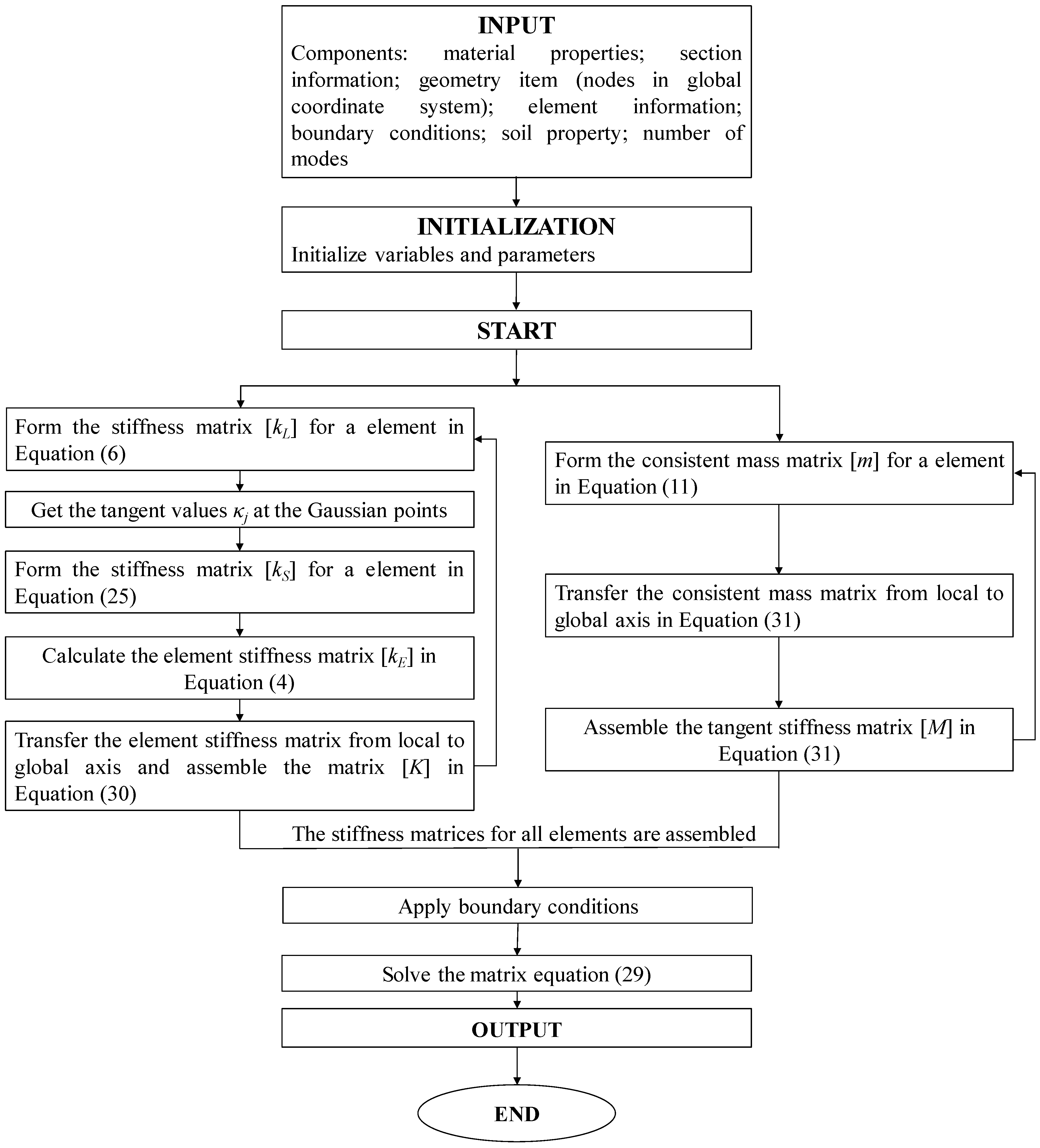
4. Numerical Analysis Procedure

The equation of motion for the free vibration of the system is given by
[ K ] { U } + [ M ] { U ¨ } = { F }
where { U } and { U ¨ } are the displacement and acceleration vectors at all degrees of freedom, respectively; [M] is the global consistent mass matrix; [K] is the global element stiffness matrix, and {F} is the force vector at the corresponding degrees of freedom. In order to estimate the system natural frequency, a trial solution of the second-order differential equation is given by:
{ U } = { A } sin ( ω t + ς )
where {A} is the vector of the amplitude of motion; ω is the circular natural frequency, and ς phase angle. The substitution of Equation (28) into Equation (27) gives an equation of eigenproblem that has specific solutions only when the determinant of ([K] − ω2[M]) is equal to zero:
| [ K ] ω 2 [ M ] | = 0
Then, the finite element analysis can be carried to find the Eigen solutions of the OWT system.
The global element stiffness matrix is correspondingly assembled as
[ K ] = i = 1 N E L E ( [ γ ] i [ k E ] i [ γ ] i T )
where NELE denotes the total number of elements and [γ]i denotes the local to global transformation matrix, which can be found in reference [43].
The global consistent mass matrix can be updated and calculated as
[ M ] = i = 1 N E L E ( [ γ ] i [ m ] i [ γ ] i T )
A numerical program for the implementation of the proposed model has been developed using Python [44]. The numerical analysis procedure is presented in Figure 5. The input data was mainly classified into material, section, geometry, element, soil property, and boundary conditions. The total global element stiffness matrix was assembled from the linear and soil stiffness matrices, and the total global mass matrix was assembled from the local consistent mass matrix. The soil stiffness matrix was achieved by p-y curves or modulus of horizontal subgrade reaction formulas along the pile depth. The entire procedure of global matrix assembly was repeated as described above until stiffness matrices for all elements were assembled. Boundary conditions were applied to element nodes according to the input requirement. Then, the matrix equation of the eigenvalue problem was solved, and the final results were outputted.

5. Model Validation

5.1. Compare with Closed-Form Solutions

In order to validate the accuracy of the element stiffness matrices, the following analyses are presented:
(1) First natural frequency analysis of the tower regarded as a simple massless beam with a top concentrated mass of MT, the length of L, and the bending stiffness of EI, comparing the proposed element with the closed-form solution (Equation (32)) reported by Paz and Kim [39].
f case 1 = 1 2 π L 3 E I M T L
(2) First and second natural frequency analysis of the tower with the material density of ρ, the length of L, and the bending stiffness of EI, comparing the proposed method with the closed-form solutions (Equations (33) and (34)) given by Clough and Penzien [45].
f case 2 = 1.7578 π L 2 E I ρ A
f case 3 = 11.5453 π L 2 E I ρ A
The following variables are used in the computation: L = 20 m; E = 30 GPa; tw = 0.045 m; D = 5 m, and ρ = 7.86 g/cm3, which fall within the reasonable range [46,47]. Figure 6 illustrates the evolution of natural frequency with tower length calculated by the proposed element and closed-form solutions (Equations (32)–(34)). The comparison results indicated that high accuracy can be achieved by adopting the proposed element for the natural frequency analysis of the tower.

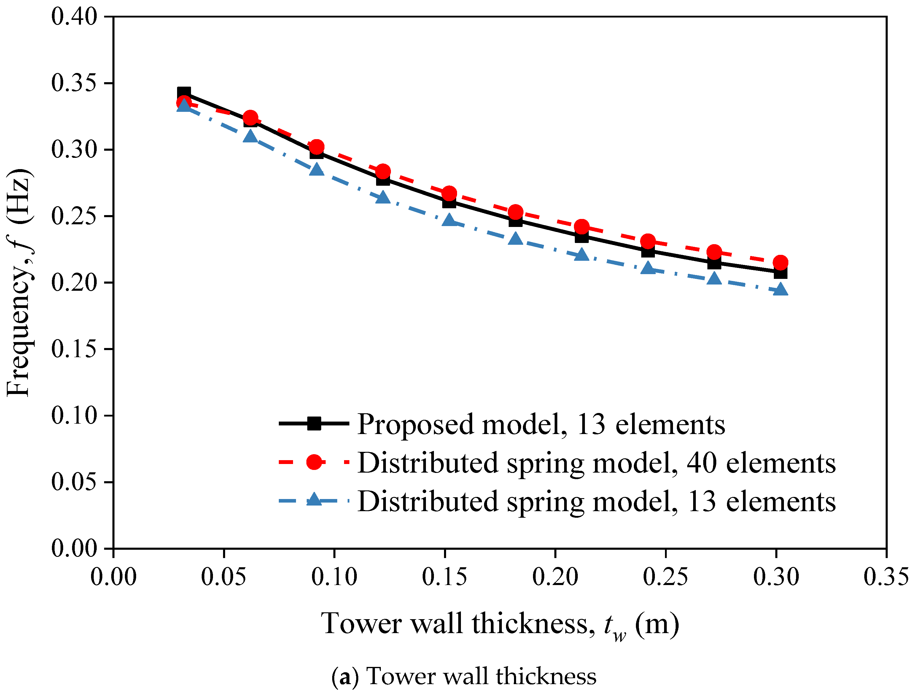
5.2. Compare with the Distributed Spring Model

This example adopts the proposed and distributed spring models to calculate the natural frequency of the OWT. Parametric analysis with different tower wall thicknesses, seabed heights, and monopile diameters was conducted to verify the accuracy and efficiency of the proposed method. The mass of the rotor and blades was 130.8 t. Tower and monopile lengths were 58 and 40 m, respectively. The diameters of the top tower, bottom tower, and monopile were 2.3, 4.45, 4.75 m, respectively. Platform length and diameter from seabed to tower bottom were 33 and 4.75 m, respectively. Tower, platform wall, and monopile thicknesses were 0.092, 0.045, and 0.08 m, respectively. The material density of tower and monopile was 7.86 g/cm3, and Young’s modulus is 210 GPa. The height of the seabed was initially located at the monopile head, and the decrease in seabed height indicated a decrease in soil depth due to scouring. The modified modulus of horizontal subgrade reaction developed by Kallehave et al. [48] was used in this section, which considers the effect of pile diameter and confining pressure and is given by:
k h = n h z 0 ( D D 0 ) m ( z z 0 ) n
in which D0 is 1.0 m; z0 is 2.5 m; m and n are 0.5 and 0.6, respectively, and, nh denotes the coefficient of subgrade reaction and is 2500 kN/m3 in this example, which falls within the normal range [49]. The natural frequency was calculated by the proposed model with 13 elements and the distributed spring model with 13 and 40 elements. As shown in Figure 7, the results of the proposed model with 13 elements matched well with distributed spring model with 40 elements, which validated the accuracy of the proposed model in calculating the natural frequency of the OWT. It can also be seen that fewer numbers of element were needed to simulate the OWT system in the proposed model when compared with the distributed spring model, which leads to a reduction in data manipulation. Due to the flexibility of the proposed element, the variations of the seabed height and structural stiffness can be easily modeled by modifying parameters within the element in this analysis.
Figure 7a shows the variation of the natural frequency with the tower wall thickness. The natural frequency decreased from 0.342 Hz to 0.208 Hz as the thickness increased from 0.0032 m to 0.302 m. Moreover, the sensitivity of natural frequency with increasing tower wall thickness reduced when the thickness exceeds 0.2 m. It can be seen from Figure 7b that the natural frequency of the system decreased with the decrease in seabed height. The effect of scour behavior on the pile bearing capacity was commonly considered in the design. Excessive natural frequency shifts due to serious scour around the piles should not be neglected either. The soil surrounding the monopile should be reinforced in the areas with serious scour to reduce the scouring effect on OWTs. Figure 7c shows that as the pile diameter increased from 2.75 m to 6.75 m, the system frequency increased from 0.204 Hz to 0.339 Hz. The natural frequency was sensitive to the variation of pile diameter for the small diameter pile, and the sensitivity to the large diameter pile gradually weakened.

5.3. Compare with the Field Measurements

To validate the applicability of the proposed model in practical engineering, the assessment of natural frequency for six different offshore wind farms (3.6 MW Gunfleet Sands, 0.6 MW Irene Vorrink, 3 MW Kentish Flats, 0.5 MW Lely A2, 2 MW North Hoyle, and 3.6 MW Walney 1) are presented. Input parameters of OWT component dimensions are gathered from references [15,19] and summarized in Table 1.
The modified modulus of horizontal subgrade reaction (Equation (35)) was used in this analysis, where the correction parameters m and n reported by Sun et al. [42] were adopted to consider the relative density of soil. The values of n were 0.5, 0.6, and 0.65 for dense, medium-dense, and loose sands, respectively. The values of m were 0.5 for dense and medium-dense sands and 0.6 for loose sand. The soil coefficient nh is obtained from Terzaghi [50]:
n h = A soil γ 1.35
where the value of Asoil is in the range of 300 to 1000 for the medium-dense sand and 100 to 300 for the loose sand, and, γ′ is the submerged unit weight and should be in the range of 7.6 to 13.2 kN/m3 for sand [51]. The values of soil coefficient Asoil = 200, 600, and 1500 are adopted in loose, medium-dense, and dense sand, respectively [50]. The recommended values of submerged unit weight were 9.76 and 10 kN/m3 in the medium-dense and dense sands, respectively [52]. Soil conditions of the six different OWTs and the adopted soil parameters are summarized in Table 2.
The predicted results of the proposed model with 13 elements are compared with the measured frequency given in the literature [15,19]. As shown in Table 3, the results of the proposed model agree well with the field measurements, indicating that the proposed model can accurately calculate the natural frequency of OWTs with the pile-soil interaction considered.

6. Conclusions

It is critical to estimate the natural frequency of the monopile supported OWT system during its lifetime. In this paper, a new unified beam-column element is developed for conveniently and reliably assessing the natural frequency of monopile supported OWTs. The following conclusions can be drawn:
(1) The proposed element enables an integrated simulation of different components of the wind turbine. It can be transformed into several shapes (i.e., hollow circular, solid circular, and tapered hollow circular sections) to model different components of OWT, which is very flexible in application. The proposed element can accurately consider the section properties’ variation of the tapered wind turbine tower along its length. The unified element tangent stiffness and consistent mass matrices are developed using analytical expressions of the flexural rigidity and mass for natural frequency analysis.
(2) The pile-soil interactions are directly integrated into the element formulations by the Gauss–Legendre integration method, making the proposed model straightforward in terms of data manipulation. There is no need to determine the stiffness for each soil spring and modify the spring properties with the variation of the element sizes. On the other hand, the proposed model requires fewer elements to simulate the soil and different components of OWT compared with the distributed spring model, which means a reduction in data manipulation.
(3) Closed-form solutions, distributed spring model, and field measurement are adopted to validate the accuracy and efficiency of the proposed element. The verifications demonstrate that the proposed OWT simulation has a wide range of applicability. The proposed element is able to apply to different components of the OWT system, including the rotor, the tower, the transition piece, and the monopile foundation. The continuous soil-pile interactions along the pile length can be accurately simulated by the proposed element using internal zero-length soil springs.
(4) Parameter studies reveal that the tower wall thickness, seabed height, and monopile diameter need to be considered in the OWT system design to obtain the optimal OWT parameter. The natural frequency of the OWT system is much more sensitive to the variation of pile diameter for the small diameter pile than the large diameter pile. The seabed height variation with natural frequency should be taken into account in the design to avoid excessive natural frequency shifts during the OWT operation. The soil surrounding the monopile with severe soil scouring should be reinforced in advance to reduce the scouring effect.

Author Contributions

Methodology, J.-H.W.; writing—original draft, J.-H.W.; writing—review & editing, J.-H.W., R.B., X.-Y.L. and S.-W.L.; project administration, X.-Y.L.; supervision, X.-Y.L.; funding acquisition, X.-Y.L. and S.-W.L. All authors have read and agreed to the published version of the manuscript.

Funding

This work was supported by the National Natural Science Foundation of China (Nos. 52279122 and 52025094) and the Guangdong Provincial Department of Science and Technology (2019ZT08G090).

Institutional Review Board Statement

Not applicable.

Informed Consent Statement

Not applicable.

Data Availability Statement

Not applicable.

Conflicts of Interest

The authors declare no conflict of interest.

Nomenclature

The following symbols are used in this paper.
DDiameter
xiCoordinate of the x-axis at the ith node
twWall thickness
IyMoment of inertia about the y-axes
IzMoment of inertia about the z-axes
ACross-sectional area
[kL]Linear stiffness matrix
[kS]Soil stiffness matrix for representing the lateral restraint from soils
EYoung’s modulus
lElement length
[m]Local consistent mass matrix
ρMaterial density
ξq,jIntegration parameter in Gauss-Legendre integration method
κjTangent values on the soil resistance versus lateral deflection curves
nNumber of Gaussian points
{U}Displacement vector at all degrees of freedom
{ U ¨ } Acceleration vectors at all degrees of freedom
[M]Global consistent mass matrix
[K]Global element stiffness matrix
{F}Force vector at the corresponding degrees of freedom
{A}Vector of the amplitude of motion
ωCircular natural frequency
ςPhase angle
NELETotal number of elements
[γ]iLocal to global transformation matrix
MTTop concentrated mass
LTotal length
khModulus of horizontal subgrade reaction
nhCoefficient of subgrade reaction
fFrequency
γSubmerged unit weight
AsoilSoil coefficient

References

  1. Snyder, B.; Kaiser, M.J. A comparison of offshore wind power development in Europe and the U.S.: Patterns and drivers of development. Appl. Energy 2009, 86, 1845–1856. [Google Scholar] [CrossRef]
  2. Yang, C.; Wang, R.; Zhang, J. A simplified method for analyzing the fundamental frequency of monopile supported offshore wind turbine system design. Earthq. Eng. Eng. Vib. 2018, 17, 893–901. [Google Scholar] [CrossRef]
  3. Zhao, L.; Xue, L.; Li, Z.; Wang, J.; Yang, Z.; Xue, Y. Progress on Offshore Wind Farm Dynamic Wake Management for Energy. J. Mar. Sci. Eng. 2022, 10, 1395. [Google Scholar] [CrossRef]
  4. Shi, Y.; Yao, W.; Yu, G. Dynamic Analysis on Pile Group Supported Offshore Wind Turbine under Wind and Wave Load. J. Mar. Sci. Eng. 2022, 10, 1024. [Google Scholar] [CrossRef]
  5. Chen, M.; Yuan, G.; Li, C.B.; Zhang, X.; Li, L. Dynamic Analysis and Extreme Response Evaluation of Lifting Operation of the Offshore Wind Turbine Jacket Foundation Using a Floating Crane Vessel. J. Mar. Sci. Eng. 2022, 10, 2023. [Google Scholar] [CrossRef]
  6. Malekjafarian, A.; Jalilvand, S.; Doherty, P.; Igoe, D. Foundation damping for monopile supported offshore wind turbines: A review. Mar. Struct. 2021, 77, 102937. [Google Scholar] [CrossRef]
  7. AlHamaydeh, M.; Hussain, S. Optimized frequency-based foundation design for wind turbine towers utilizing soil–structure interaction. J. Frankl. Inst. 2011, 348, 1470–1487. [Google Scholar] [CrossRef]
  8. Zaaijer, M.B. Foundation modelling to assess dynamic behaviour of offshore wind turbines. Appl. Ocean Res. 2006, 28, 45–57. [Google Scholar] [CrossRef]
  9. Bisoi, S.; Haldar, S. Dynamic analysis of offshore wind turbine in clay considering soil–monopile–tower interaction. Soil Dyn. Earthq. Eng. 2014, 63, 19–35. [Google Scholar] [CrossRef]
  10. Arshad, M.; O’Kelly, B.C. Offshore wind-turbine structures: A review. Proc. Inst. Civ. Eng. Energy 2013, 166, 139–152. [Google Scholar] [CrossRef]
  11. Bhattacharya, S.; Cox, J.A.; Lombardi, D.; Muir Wood, D. Dynamics of offshore wind turbines supported on two foundations. Proc. Inst. Civ. Eng. Geotech. Eng. 2013, 166, 159–169. [Google Scholar] [CrossRef] [Green Version]
  12. Lombardi, D.; Bhattacharya, S.; Muir Wood, D. Dynamic soil–structure interaction of monopile supported wind turbines in cohesive soil. Soil Dyn. Earthq. Eng. 2013, 49, 165–180. [Google Scholar] [CrossRef]
  13. Fei, C.; Wang, N.; Zhou, B.; Chen, C. Dynamic Performance Investigation for Large-Scale Wind Turbine Tower. In Proceedings of the 2005 International Conference on Electrical Machines and Systems, Nanjing, China, 27–29 September 2005; pp. 996–999. [Google Scholar]
  14. Van Der Tempel, J. Design of Support Structures for Offshore Wind Turbines. Ph.D. Thesis, Delft University of Technology, Delft, The Netherlands, 2006. [Google Scholar]
  15. Arany, L.; Bhattacharya, S.; Macdonald, J.H.G.; Hogan, S.J. Closed form solution of Eigen frequency of monopile supported offshore wind turbines in deeper waters incorporating stiffness of substructure and SSI. Soil Dyn. Earthq. Eng. 2016, 83, 18–32. [Google Scholar] [CrossRef] [Green Version]
  16. Alkhoury, P.; Soubra, A.H.; Rey, V.; Aït-Ahmed, M. A full three-dimensional model for the estimation of the natural frequencies of an offshore wind turbine in sand. Wind Energy 2020, 24, 699–719. [Google Scholar] [CrossRef]
  17. Adhikari, S.; Bhattacharya, S. Dynamic analysis of wind turbine towers on flexible foundations. Shock Vib. 2012, 19, 408493. [Google Scholar] [CrossRef]
  18. Arany, L.; Bhattacharya, S.; Adhikari, S.; Hogan, S.J.; Macdonald, J.H.G. An analytical model to predict the natural frequency of offshore wind turbines on three-spring flexible foundations using two different beam models. Soil Dyn. Earthq. Eng. 2015, 74, 40–45. [Google Scholar] [CrossRef] [Green Version]
  19. Amar Bouzid, D.; Bhattacharya, S.; Otsmane, L. Assessment of natural frequency of installed offshore wind turbines using nonlinear finite element model considering soil-monopile interaction. J. Rock Mech. Geotech. Eng. 2018, 10, 333–346. [Google Scholar] [CrossRef]
  20. Ko, Y. A simplified structural model for monopile-supported offshore wind turbines with tapered towers. Renew. Energy 2020, 156, 777–790. [Google Scholar] [CrossRef]
  21. Cao, Q.; Li, H.; Tang, G.; Wang, B.; Lu, L. Dynamic analysis of monopile OWTs with viscoelastic dampers based on pole-residue method. Ocean Eng. 2022, 266, 113167. [Google Scholar] [CrossRef]
  22. Andersen, L.V.; Vahdatirad, M.J.; Sichani, M.T.; Sørensen, J.D. Natural frequencies of wind turbines on monopile foundations in clayey soils—A probabilistic approach. Comput. Geotech. 2012, 43, 1–11. [Google Scholar] [CrossRef]
  23. Shirgir, V.; Ghanbari, A.; Shahrouzi, M. Natural frequency of single pier bridges considering soil-structure interaction. J. Earthq. Eng. 2015, 20, 611–632. [Google Scholar] [CrossRef]
  24. Darvishi-Alamouti, S.; Bahaari, M.-R.; Moradi, M. Natural frequency of offshore wind turbines on rigid and flexible monopiles in cohesionless soils with linear stiffness distribution. Appl. Ocean Res. 2017, 68, 91–102. [Google Scholar] [CrossRef]
  25. Roy, J.; Kumar, A.; Choudhury, D. Natural frequencies of piled raft foundation including superstructure effect. Soil Dyn. Earthq. Eng. 2018, 112, 69–75. [Google Scholar] [CrossRef]
  26. De Risi, R.; Bhattacharya, S.; Goda, K. Seismic performance assessment of monopile-supported offshore wind turbines using unscaled natural earthquake records. Soil Dyn. Earthq. Eng. 2018, 109, 154–172. [Google Scholar] [CrossRef]
  27. Plodpradit, P.; Dinh, V.; Kim, K.D. Coupled analysis of offshore wind turbine jacket structures with pile-soil-structure interaction using FAST v8 and X-SEA. Appl. Sci. 2019, 9, 1633. [Google Scholar] [CrossRef] [Green Version]
  28. Williams, S.A.; Pelecanos, L.; Darby, A.P. A Winkler model of monopile ratcheting under long-term dynamic cyclic loading. Ocean Eng. 2022, 266, 112625. [Google Scholar] [CrossRef]
  29. Sunday, K.; Brennan, F. Influence of soil–structure modelling techniques on offshore wind turbine monopile structural response. Wind Energy 2022, 25, 998–1012. [Google Scholar] [CrossRef]
  30. Chiou, J.S.; Lin, C.L.; Chen, C.H. Exploring influence of sectional flexural yielding on experimental pile response analysis and applicability of distributed plastic hinge model in inelastic numerical simulation for laterally loaded piles. Comput. Geotech. 2014, 56, 40–49. [Google Scholar] [CrossRef]
  31. Carswell, W.; Arwade, S.R.; DeGroot, D.J.; Lackner, M.A. Soil-structure reliability of offshore wind turbine monopile foundations. Wind Energy 2015, 18, 483–498. [Google Scholar] [CrossRef]
  32. Li, X.y.; Wan, J.h.; Liu, S.w.; Zhang, L.m. Numerical formulation and implementation of Euler-Bernoulli pile elements considering soil-structure-interaction responses. Int. J. Numer. Anal. Methods Geomech. 2020, 44, 1903–1925. [Google Scholar] [CrossRef]
  33. Banerjee, J.; Williams, F. Exact Bernoulli–Euler dynamic stiffness matrix for a range of tapered beams. Int. J. Numer. Methods Eng. 1985, 21, 2289–2302. [Google Scholar] [CrossRef]
  34. Bai, R.; Liu, S.W.; Chan, S.L. Finite-element implementation for nonlinear static and dynamic frame analysis of tapered members. Eng. Struct. 2018, 172, 358–381. [Google Scholar] [CrossRef]
  35. El Gendy, O.; Sallam, E.; Mohamedien, M.A. Finite element formulation of Timoshenko tapered beam-column element for large displacement analysis based on the exact shape functions. Aust. J. Struct. Eng. 2022, 23, 269–288. [Google Scholar] [CrossRef]
  36. Wan, J.H.; Liu, S.W.; Li, X.Y.; Zhang, L.M.; Zhao, H.P. Buckling analysis of tapered piles using non-prismatic beam-column element model. Comput. Geotech. 2021, 139, 104370. [Google Scholar] [CrossRef]
  37. Gautschi, W. Numerical Analysis; Springer Science & Business Media: Berlin, Germany, 2011. [Google Scholar]
  38. Hutton, D.V. Fundamentals of Finite Element Analysis; McGraw-Hill Science Engineering: New York, NY, USA, 2003. [Google Scholar]
  39. Paz, M.; Kim, Y.H. Structural Dynamics: Theory and Computation, 6th ed.; Springer International Publishing: Cham, Switzerland, 2019. [Google Scholar]
  40. DNV, G. DNV-OS-J101–Design of offshore wind turbine structures. DNV GL Oslo Nor. 2014. [Google Scholar]
  41. Jeong, S.; Kim, Y.; Kim, J. Influence on lateral rigidity of offshore piles using proposed p–y curves. Ocean Eng. 2011, 38, 397–408. [Google Scholar] [CrossRef]
  42. Sun, Y.; Xu, C.; Du, X.; El Naggar, M.H.; Zhang, X.; Jia, J. Nonlinear lateral response of offshore large-diameter monopile in sand. Ocean Eng. 2020, 216, 108013. [Google Scholar] [CrossRef]
  43. Li, X.Y.; Wan, J.H.; Zhao, H.P.; Liu, S.W. Three-Dimensional analysis of nonlinear pile–soil interaction responses using 3D pile element model. Int. J. Geomech. 2021, 21, 04021129. [Google Scholar] [CrossRef]
  44. Van Rossum, G.; Drake, F. Python 3 Reference Manual; Createspace: Scotts Valley, CA, USA, 2009. [Google Scholar]
  45. Clough, R.W.; Penzien, J. Dynamics of Structures, Computers & Structures; Computers & Structures, Inc.: New York, NY, USA, 1995. [Google Scholar]
  46. Eskandari, H.; Nik, M.G.; Pakzad, A. Foundation analyzing of centrifugal ID fans in cement plants. Alex. Eng. J. 2016, 55, 1563–1572. [Google Scholar] [CrossRef] [Green Version]
  47. Bhartiya, P.; Chakraborty, T.; Basu, D. Nonlinear subgrade modulus of sandy soils for analysis of piled raft foundations. Comput. Geotech. 2020, 118, 103350. [Google Scholar] [CrossRef]
  48. Kallehave, D.; Thilsted, C.L.; Liingaard, M.A. Modification of the API p-y formulation of initial stiffness of sand. In Proceedings of the Offshore Site Investigation and Geotechnics: Integrated Technologies-Present and Future, London, UK, 12 September 2012. [Google Scholar]
  49. Chaudhuri, D. Liquefaction and Lateral Soil Movement Effects on Piles; Cornell University: Ithaca, NY, USA, 1998. [Google Scholar]
  50. Terzaghi, K. Evalution of conefficients of subgrade reaction. Geotechnique 1955, 5, 297–326. [Google Scholar] [CrossRef]
  51. Zekkos, A.; Woods, R.; Grizi, A. Effect of Pile-Driving Induced Vibrations on Nearby Structures and Other Assets; University of Michigan: Ann Arbor, MI, USA, 2013. [Google Scholar]
  52. Thieken, K.; Achmus, M.; Lemke, K. A new static p-y approach for piles with arbitrary dimensions in sand. Geotechnik 2015, 38, 267–288. [Google Scholar] [CrossRef]
  53. May, J. Post-construction results from the North Hoyle offshore wind farm. In Proceedings of the Copenhagen Offshore Wind International Conference, Copenhagen, Denmark, 26 September 2005; pp. 1–10. [Google Scholar]
Figure 1. The monopile supported OWT and its equivalent models.
Jmse 11 00628 g001
Figure 2. Frequency of a three-bladed wind turbine.
Jmse 11 00628 g002
Figure 3. Proposed unified beam-column element model for OWT system.
Jmse 11 00628 g003
Figure 4. Relationship of soil resistance versus displacement for the monopile embedding in multi-layer soil.
Jmse 11 00628 g004
Figure 5. Flow chart of the numerical analysis procedure.
Jmse 11 00628 g005
Figure 6. Natural frequency against tower length in different cases [39,45].
Jmse 11 00628 g006
Figure 7. Comparisons of natural frequency between two modelling methods with the variation of OWT parameters.
Jmse 11 00628 g007aJmse 11 00628 g007b
Table 1. Input parameters for predicting the natural frequency of six OWTs.
OWT Component Dimension (Unit)Gunfleet SandsIrene VorrinkKentish FlatsLely A2North HoyleWalney 1
Mass of the rotor and blades (ton)234.535.7130.832100234.5
Material density of tower and monopile (g/cm3)7.867.867.867.867.867.86
Tower length (m)6044.560.0637.96767.3
Tower Young’s modulus (GPa)210210210210210210
Tower top diameter (m)31.72.31.92.33
Tower bottom diameter (m)53.54.453.245
Tower wall thickness (mm)331322133540
Platform length from pile head to tower bottom (m)285.2~61612.1737.3
Platform diameter (m)53.54.33.246
Platform wall thickness (mm)502845355080
Monopile diameter (m)53.54.33.246
Monopile wall thickness (mm)942845355080
Total length of monopile (m)3824.629.513.53323.5
Length of monopile in soil (m)271925303323.5
Monopile Young’s modulus (GPa)210210210210210210
Table 2. Soil conditions and parameters of the six OWTs.
Wind Farm NameSoil Conditions [15,53]Asoil [50] γ′ (kN/m3) [52]m [42]n [42]
Gunfleet SandsCross-bedded Holocene sand with intermittent layers of soft clay6009.760.50.6
Irene VorrinkSoft layers of silt and clay in the upper seabed to dense sand and very dense sand below6009.760.50.6
Kentish FlatsLayers of dense sand and firm clay1500100.50.5
Lely A2Soft clay in the uppermost layer to dense and very dense sand layers below6009.760.50.6
North HoyleSand and sandy gravels with varying amounts of stone and minor clay/silt content6009.760.50.6
Walney 1Medium and dense sand layers1500100.50.5
Table 3. Predicted and measured natural frequencies of all OWTs.
Wind Farm NameMeasured Frequency (Hz)Predicted Frequency (Hz)Difference (%)
Gunfleet Sands0.3140.3171.0
Irene Vorrink0.546~0.5630.557~0.5640.2~2.0
Kentish Flats0.3390.3380.3
Lely A20.6340.6411.1
North Hoyle0.3500.3623.4
Walney 10.3500.3354.3
Disclaimer/Publisher’s Note: The statements, opinions and data contained in all publications are solely those of the individual author(s) and contributor(s) and not of MDPI and/or the editor(s). MDPI and/or the editor(s) disclaim responsibility for any injury to people or property resulting from any ideas, methods, instructions or products referred to in the content.

