Article

Analysis of Water Resonance in the Inner Domain of a Large Fixed Floating Tourist Platform Based on a 3D Non-Hydrostatic Model

1
State Key Laboratory of Coastal and Offshore Engineering, Dalian University of Technology, No. 2 Linggong Road, Ganjingzi District, Dalian 116024, China
2
China Ship Scientific Research Center, No. 222 East Shanshui Road, Binhu District, Wuxi 214082, China
*
Author to whom correspondence should be addressed.
J. Mar. Sci. Eng. 2023, 11(3), 649; https://doi.org/10.3390/jmse11030649
Submission received: 16 February 2023 / Revised: 13 March 2023 / Accepted: 18 March 2023 / Published: 20 March 2023
(This article belongs to the Section Ocean Engineering)

Abstract

:
In order to meet the needs of marine tourism development, this paper analyzes the water resonance in the inner domain of a fixed floating tourist platform based on a 3D non-hydrostatic model. The tourist platform has a complex structure that is prone to the resonance of the water in the inner domain under wave actions. The water’s motion response in the platform’s inner domain under wave action is simulated numerically using numerical simulation methods. The non-hydrostatic model used in this paper is based on a semi-implicit method to solve the incompressible Navier–Stokes equations (NSE) and combines the immersed boundary method with the global continuity equations in the pressure zone (the flow zone under the structure) to approach the problem. In this paper, firstly, the resonant frequencies and resonant amplitudes of the water inside the box-shaped ship are calculated and compared with the experimental data to demonstrate the non-hydrostatic model’s accuracy in calculating the resonance problem of the water in the inner domain of a fixed floating platform. Secondly, the water’s resonant frequencies and resonant modes in the inner domain are calculated by numerical modeling of the floating tourist platform, including rare high-order resonance modes. We found that there are six resonance modes with complex shapes in the water of the inner domain of the tourist platform. Furthermore, the effects of the wall thickness, chord distance and draft of the annular tourist platform on the resonant amplitude values and modes of the water domain within the platform are analyzed in depth.

1. Introduction

The floating platforms with the internal domain are very common in coastal or ocean engineering; they can be used to build floating breakwaters, drilling and mining platforms, floating cities at sea, etc. In order to promote ocean tourism, a floating tourist platform that combines functionality and spectacle is proposed. The tourist platform comes with an inner water area for swimming and water play, as well as yacht mooring. Due to the influence of waves, water resonance will occur in the internal water of the tourist platform, which affects the tourists’ water play and the stability of the yachts’ mooring. Ravinthrakumar et al. [1] studied the factors influencing each higher-order resonant mode in rectangular water in a ship, and when the ship moves in irregular waves, each higher-order mode may also be excited if the size of the rectangular water is large enough. It is also worth investigating whether multiple higher-order resonant modes exist for a tourist platform, which is a very large floating structure. Therefore, it is necessary to study the water’s resonance in the internal domain of the floating tourist platform in the design stage.
With the development of ocean engineering to the deep sea, floating platforms have become a hot topic in the research field. The violent inner domain water resonance will amplify the wave amplitude, make the inner platform domain accumulate more wave energy, and return to the platform, which will cause irreversible harm to the floating platform structure and affect its normal marine production and life activities. Thus, the researcher analyzed and studied the response frequencies [2,3,4], mode distributions [5], response amplitudes [6,7] and the factors affecting the water resonance [8] in the inner domain of the floating platform.
The method of studying water resonance is generally divided into physical model experiments and numerical simulation experiments. As a type of very large floating structure, the floating tourist platform is large, and if physical model tests are conducted, the influence of the model construction similarity criterion should be considered. Numerical simulation trials have been developed for many years and are widely used in the field of ocean engineering. The numerical simulation of water resonance in the inner domain of the floating platform is generally based on the potential flow and viscous flow models. The potential flow model is highly efficient in the calculation but ignores the viscosity of water and cannot accurately calculate the resonant wave surface response. The viscous flow model, based on NSE, can accurately calculate the wave surface response, but its computational efficiency is low, and its cost is high. In practical engineering, the wave surface elevation of the water, when resonance occurs, is one of the key concerns. Therefore, it has been the goal of researchers to seek an accurate and efficient numerical model to calculate the hydrodynamic response of complex structures.
The development of non-hydrostatic models began in the late 1990s and was first proposed by Casulli and Stelling [9] and Stansby and Zhou [10]. The advantage of the non-hydrostatic model over the traditional viscous flow model is its computational efficiency. The free-surface elevation is only defined as a single-valued function of the horizontal position, and the kinematic free-surface boundary condition can effectively track the surface motion with relatively small computational costs. Nowadays, non-hydrostatic models can simulate wave motion deformation [11,12,13,14,15] and wave breaking [16,17,18], and some non-hydrostatic models can simulate wave interactions with structures [19,20,21,22,23] as well as the effect of vegetation on wave propagation [24,25], and even tsunami propagation [26]. However, the assumption that the wave surface is a single-valued function of the horizontal position in the non-hydrostatic model makes it complicated for the non-hydrostatic model to simulate the case in which the bottom permeable surface of the building is exposed to the water, and the introduction of the immersed boundary condition may solve this problem. The non-hydrostatic models adopt the direct-forcing immersed boundary (IB) method to simulate wave interactions with structures [20,27,28], which are treated as virtual bodies, and non-slip boundary conditions are used on the surface of the structure. This provides the non-hydrostatic model with the ability to calculate the resonance of the water in the inner domain of the floating platform.
After years of effort, an efficient 3D non-hydrostatic model has been developed [21]. The model combines the IB method with the global continuity equation in the pressurized region, maintains the symmetry of Poisson’s equation, and improves the computational efficiency of the model using GPU parallel technology. In this paper, based on the existing model [21], a viscous term is added to the control equation to develop an efficient three-dimensional non-hydrostatic model for calculating the water resonance in the inner region of a fixed floating tourist platform. Firstly, the computational analysis of the water resonance in the inner region of the box-shaped ship was performed and compared with the physical model experiments performed by [7]. The results achieved good agreement and proved the accuracy of the non-hydrostatic model in calculating the water resonance in the inner region of the fixed floating platform. Then, the resonant frequencies and modes distributions of the floating tourist platform are calculated, and the wall thickness, chord distance and draft that affect the resonance of its inner domain water are studied and analyzed.

2. Numerical Model

2.1. Governing Equations

The 3D non-hydrostatic free-surface flow is governed by the incompressible NSE. The conservation of the mass and momentum equations can be expressed in the following form by splitting the pressure into hydrostatic and non-hydrostatic components, p = g η z + q .
u x + v y + w z = 0
u t + u 2 x + u v y + u w z = g η x q x + υ 2 u x 2 + 2 u y 2 + 2 u z 2
v t + u v x + v 2 y + v w z = g η y q y + υ 2 v x 2 + 2 v y 2 + 2 v z 2
w t + u w x + v w y + w 2 z = q y + υ 2 w x 2 + 2 w y 2 + 2 w z 2
where t is the time, u , v , w are the velocity components in the horizontal x , y and vertical z directions, respectively; p is the normalized pressure divided by a constant reference density; q is the non-hydrostatic pressure component; η is the free-surface elevation; g is the gravitational acceleration, and υ is the eddy kinematic viscosity (see Figure 1). The definition of each variable in the grid system is shown in Figure 2, where ω i , j , k + 1 / 2 is the vertical velocity relative to layer level z k + 1 / 2 [29].

2.2. Boundary Conditions

Boundary conditions are required at all the boundaries of a 3D wave value flume. In the free-surface region η x , y , t , the kinematic boundary condition is
η t + u η x + v η y = w z = η
In the pressurized domain, the kinematic boundary of the body surface is
u d x v d y = w z = d
where z = d x , y is the body surface (see Figure 1).
At the impermeable bottom surface, the kinematic boundary condition is
u h x v h y = w z = h
Integrating Equation (1) from the bottom surface z = h x , y to the free surface z = η x , y , t , and applying Leibniz’s rule with Equations (5) and (7), the free-surface equation is obtained:
η t + x h η u d z + y h η v d z = 0
Similarly, the free-surface equation in the pressurized region can be expressed as:
x h d u d z + y h d v d z = 0
In addition, in the inflow boundary, the velocity boundary wave-generation method is applied, the incident wave normal velocity is determined by the analytical solution equation, and the tangential velocity is set to zero. Both sides of the flume are impermeable solid wall boundaries. At the outflow boundary, a sponge layer is set to minimize wave reflection.

2.3. Numerical Algorithms

The governing equations are discretized on a 3D grid system, which is constructed from a 2D horizontal structured grid with multiple horizontal layers. In the vertical general boundary-fitted coordinate system (see Figure 1), the horizontal level is defined, as shown in Equation (10).
z k + 1 / 2 = z f + k k f η x , y , t z f / N z k f k > k f z f k = k f h x , y + k z f + h x , y / k f k < k f
where k is the grid index of the number of vertical layers; N z is the total number of vertical layers; where z f and k f are the predefined fixed horizontal level and layer indexes, respectively. The horizontal level above z f is a function of the time and moves with the free surface at each time, while below it, it is a function of the space, and they are fixed due to the immovability of the bottom surface in this study.
The governing equations are first integrated along the vertical direction in a general boundary-fitted coordinate system [12]. For details of the discretization of the momentum equation, the reader is referred to [20].

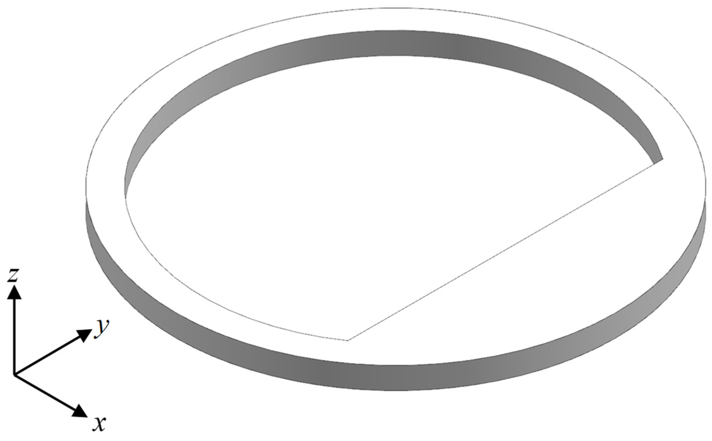
2.4. Description of the Tourist Platform

Figure 3 shows the schematic diagram of the floating tourist platform structure. The coordinate system in the figure is used as an indication of direction only. Unlike moonpools and harbors, the floating tourist platform is a circular thin-walled structure with a large area of water inside the platform, beyond which there exists a region enclosed by a straight line (which is known as a chord in mathematics) and circular curve in the inner domain of the platform. The complex structural characteristics may make the inner domain of the platform with multiple resonant frequencies and water resonance patterns more complex. Therefore, an accurate and effective prediction of the resonant response of the water surface inside the floating tourist platform under the wave action, and analysis of its resonant frequencies and modes, are essential for its safety assessment and structural optimization in the design phase.

3. Model Validation

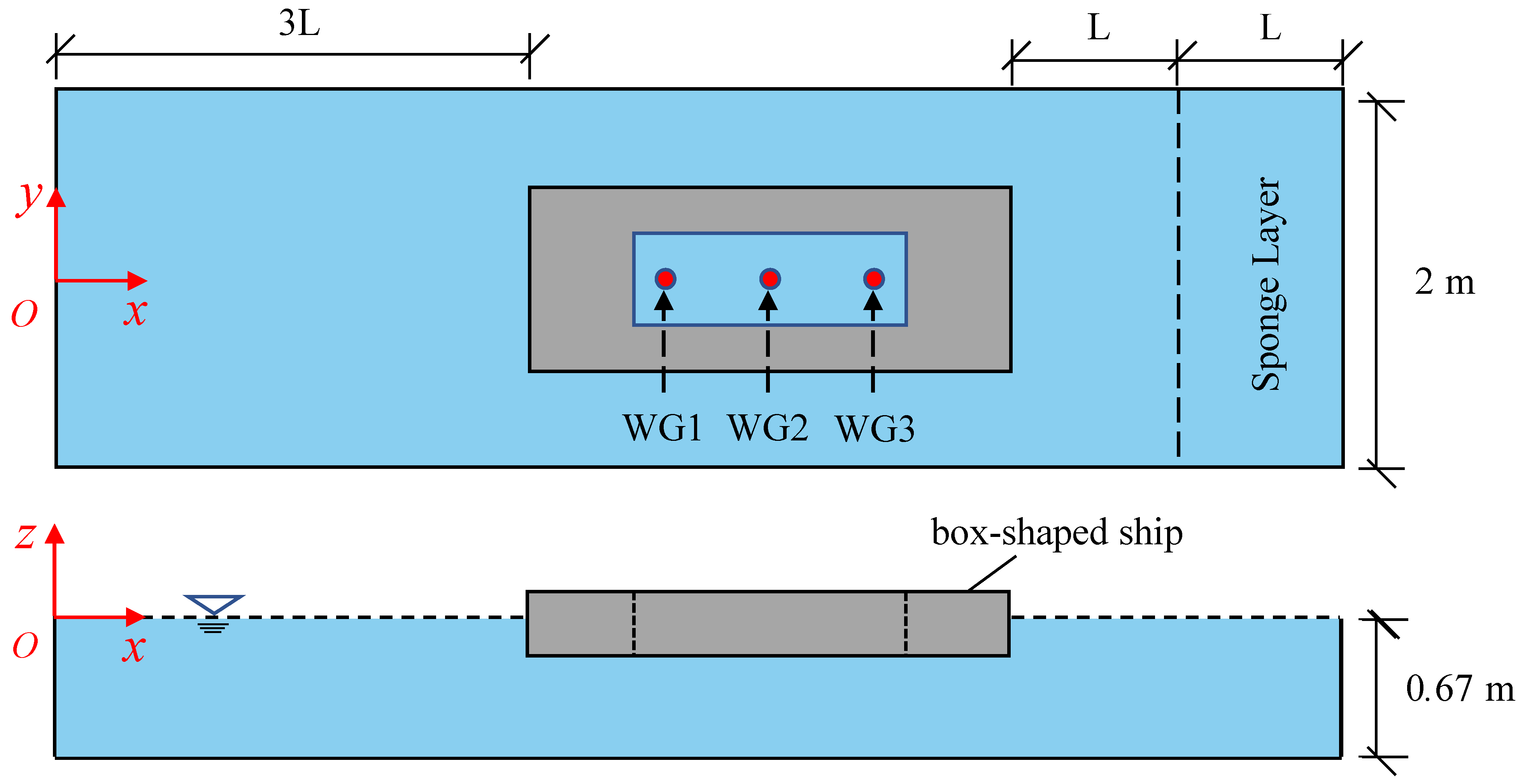
In this test case, the resonant frequencies and resonant amplitudes of the water in the rectangular internal domain of the box-shaped ship under wave action are considered. The results of the model’s calculation in this paper are compared with the experimental data from Price, Magee and Feng [7]. As shown in Figure 4, the floating box-shaped ship has the dimensions of L x = 2.0   m , L y = 0.3   m , L z = 0.3   m , and the rectangular internal domain has the dimensions of l x = 0.4   m , l y = 0.2   m , l z = 0.3   m . The coordinate origin is located at the center of the wave-making boundary at the still-water surface. In all tests, the water depth is 0.67 m, and the draft of the ship is 0.16 m. The incident waves are regular waves that are generated with linear wave theory. The wave height H 0 = 0.06   m , the wave frequency range f = 0.5 ~ 2.0   Hz , and the frequency interval Δ f = 0.05   Hz . The length of the numerical flume is determined by the wavelength L , and for each wave, a minimum of three wavelengths were generated before reaching the bow of the ship. Three evenly spaced wave gauges (WG) are located on the centerline of the moonpool, where WG 1 (closest to the bow) and WG 3 (stern) are located at 0.02 m from both sides of the inner wall of the ship and WG 2 is located in the middle of the moonpool. According to Price, Magee and Feng [7], WG3 always records the maximum wave elevation when water resonance occurs in the inner domain of the ship. Subsequently, WG 3 is employed as a representative of the free-surface elevation in the inner domain of the ship.
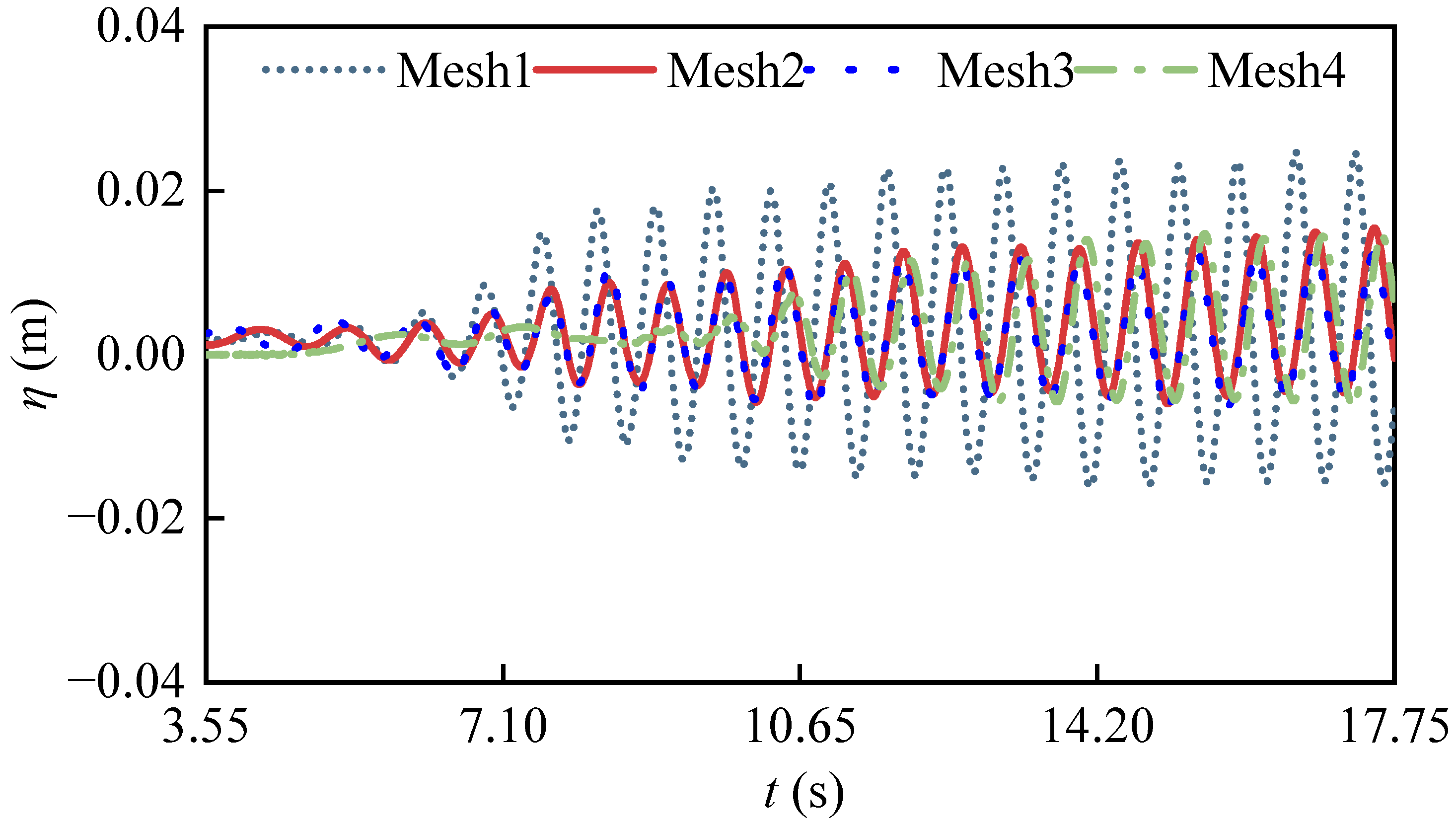
First, select the case with a wave frequency of 1.4   Hz , and four different grid configurations are then to be used for the grid convergence verification; detailed information is shown in Table 1. In the whole computational domain, a uniform horizontal grid is used. With the four grid configurations, the free-surface elevations of the ship’s inner domain are plotted in Figure 5. The simulation on Mesh1 predicts larger values of free-surface elevation than the simulations on the other grids, and the numerical results calculated on Mesh2, Mesh3 and Mesh4 are closer to each other. Considering the computational cost and efficiency, all cases are calculated using Mesh2.
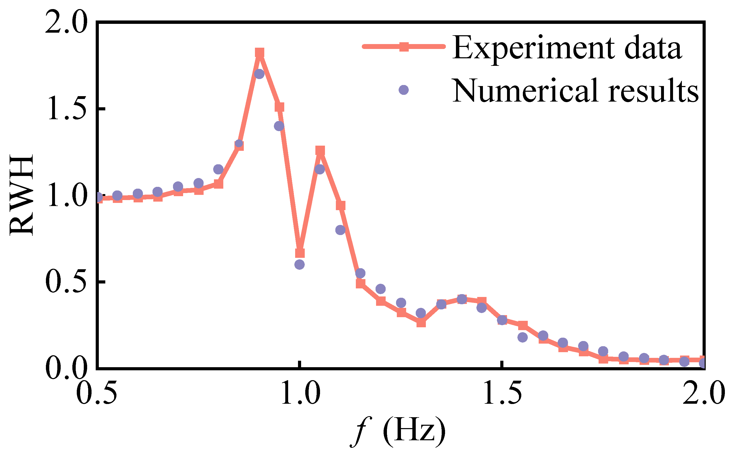
Figure 6 shows the comparison of the resonant frequencies and resonant amplitude values of the water in the inner domain of the box-shaped ship calculated by the non-hydrostatic model with the experimental results from Price, Magee and Feng [7]. RWH is the relative wave height of WG3, which is determined by the wave height ratio in the ship’s inner domain, recorded by the wave gauge to the incident wave height. From Figure 6, it can be seen that the frequency locations of the piston mode and the first-order sloshing mode, calculated by the non-hydrostatic model, are the same as the experimental results, which indicates that the model has good dispersion characteristics for both long-wave and short-wave. The root mean square error between the predicted free-surface elevation of the inner domain of the ship and the experimental results is 5.68%, which is in good agreement overall.

4. Water Resonance in the Inner Domain of the Floating Tourist Platform

4.1. Numerical Setup

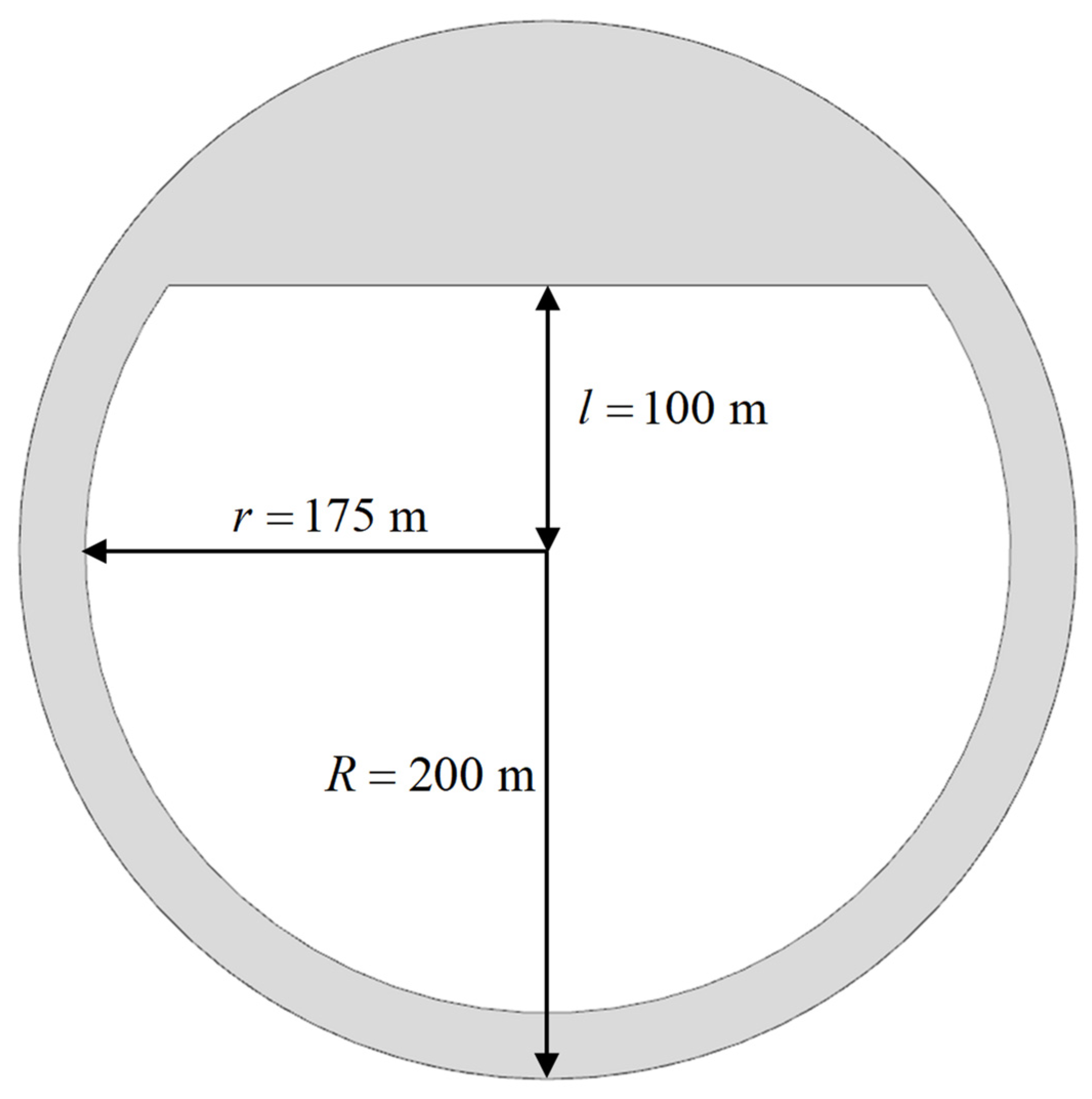
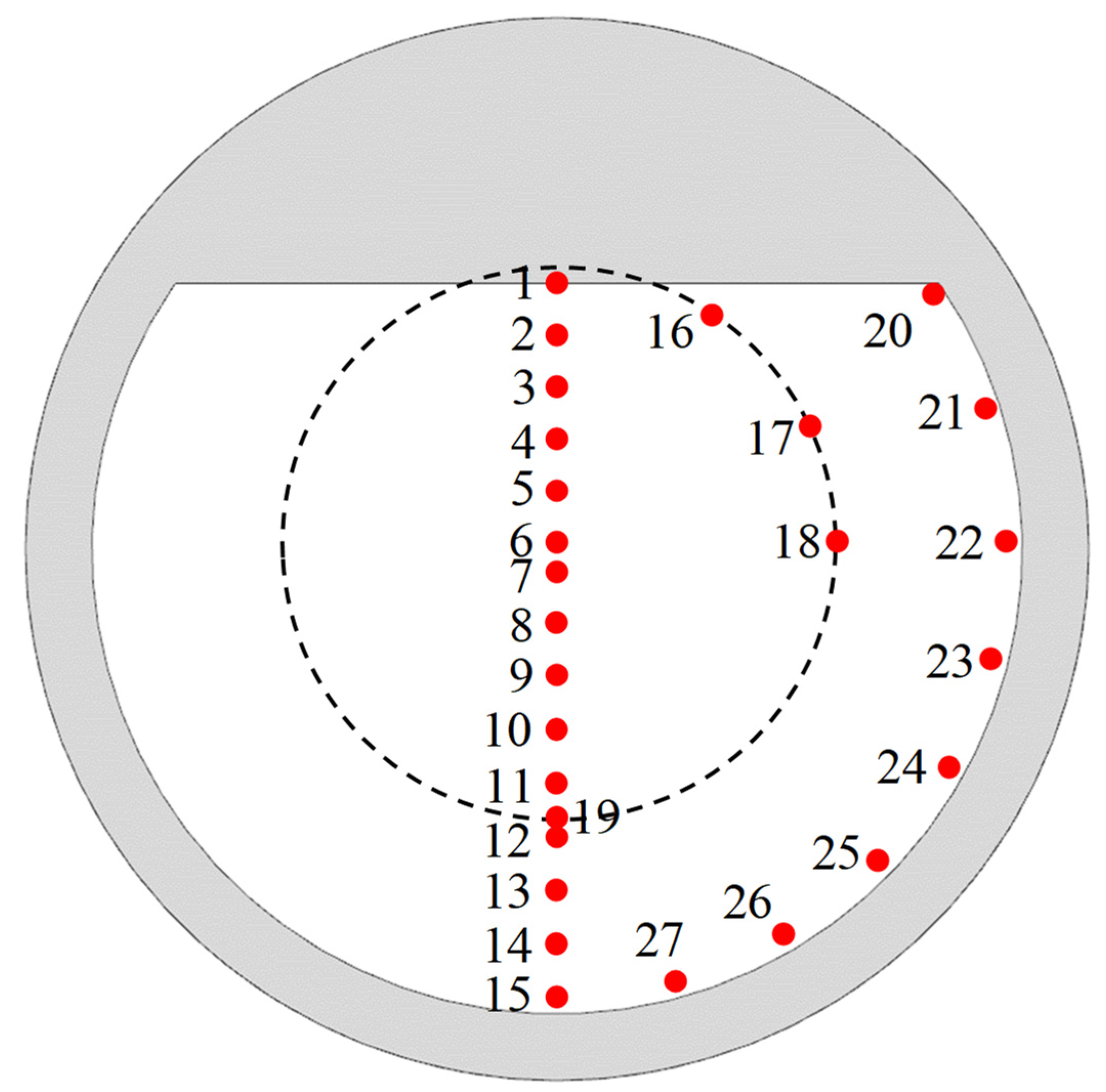
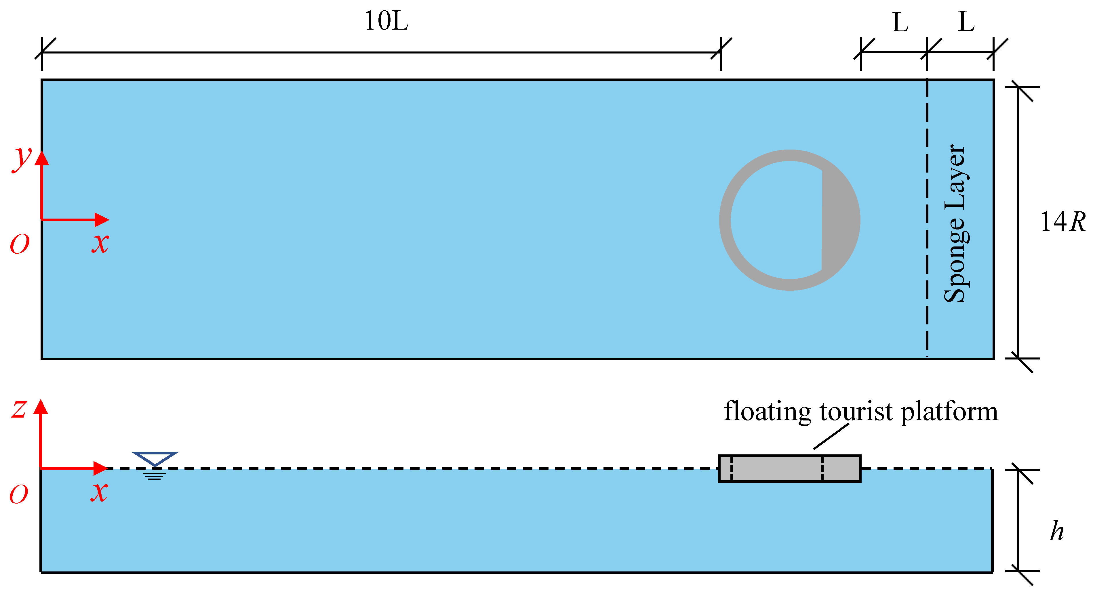
In this case, a large-scale and complex-shaped floating tourist platform with inner domain water resonance is considered. As shown in Figure 7, the platform has the dimensions of R = 200   m , r = 175   m , a chord distance of l = 100   m and a vertical height of l z = 25   m . The structure of the floating tourist platform is symmetrical and similar to the closed circular harbors. The maximum elevation of the oscillating wave surface in closed circular harbors tends to occur at the symmetry axis along the wave propagation direction and at the solid wall boundary. As shown in Figure 8, twenty-seven wave gauges are placed in the inner domain of the platform, and the free-surface elevation, captured by each wave gauge under different wave motions, is recorded, where the maximum value is taken as the representative of the free-surface elevation for that working condition. Figure 9 shows the computational domain, where the platform is 10 wavelengths away from the wavemaker, and a sponge layer is set at the end of the calculation domain to absorb wave energy. The coordinate origin is located at the center of the wave-making boundary at the still-water surface. The draft of the platform is 10 m, and the still-water depth is h = 50   m in the computational domain. The incident wave is the regular wave generated with linear wave theory. The wave height H 0 = 1.0   m , the wave frequencies range ω = 0.1 ~ 0.9   rad / s , and the frequency range includes common wave frequency waves for ocean engineering and long-period waves.

4.2. Resonant Frequencies and Modes

In the numerical simulation of the floating tourist platform, an encrypted grid is used locally in the platform area, and the horizontal grid spacing of Δ x = Δ y = 2.5   m , as well as a vertical grid system, is constructed by using 14 layers with z f = 10   m and k f = 8 . The time step is controlled by setting the maximum Courant number (CFL) to CFL = 0.4 , and the total simulation time is up to 30 ~ 40 wave periods. Figure 10 shows the resonant response of the water in the inner domain of the floating tourist platform in the frequency domain calculated by the non-hydrostatic pressure model. It can be seen that there are eight peaks in the RWH curve of the water resonance in the inner domain of the floating tourist platform. These eight peaks correspond to the modes named M1~M8 according to the frequencies from low to high. From Table 2, the M1~M6 modes of the floating tourist platform RWH > 1 , M7~M8 modes’ RWH 1 , and the M3 mode RWH value is a maximum of 2.75, while the resonance of the water in the inner domain of the floating tourist platform is more obvious. Except for the M1 mode, which is excited by long-period waves, all the other modes excited by wave frequencies belong to common wave frequencies. As we know, long waves are more penetrating than short waves. As the wave frequencies continue increasing, the wave energy entering the inner domain of the platform decreases, the resonant modes are harder to excite, and the resonant amplitude gradually decreases. In contrast to the circular moonpools and circular harbors resonance, the water domain’s maximum wave surface response mode within the floating tourist platform is the M3 instead of the M1. When the resonant modes in the common wave frequencies range are excited, the maximum wave surface elevation of the water domain in the platform is larger than the incident wave, and it is necessary to take measures to restrict the amplitude of the resonant mode response in engineering practice.
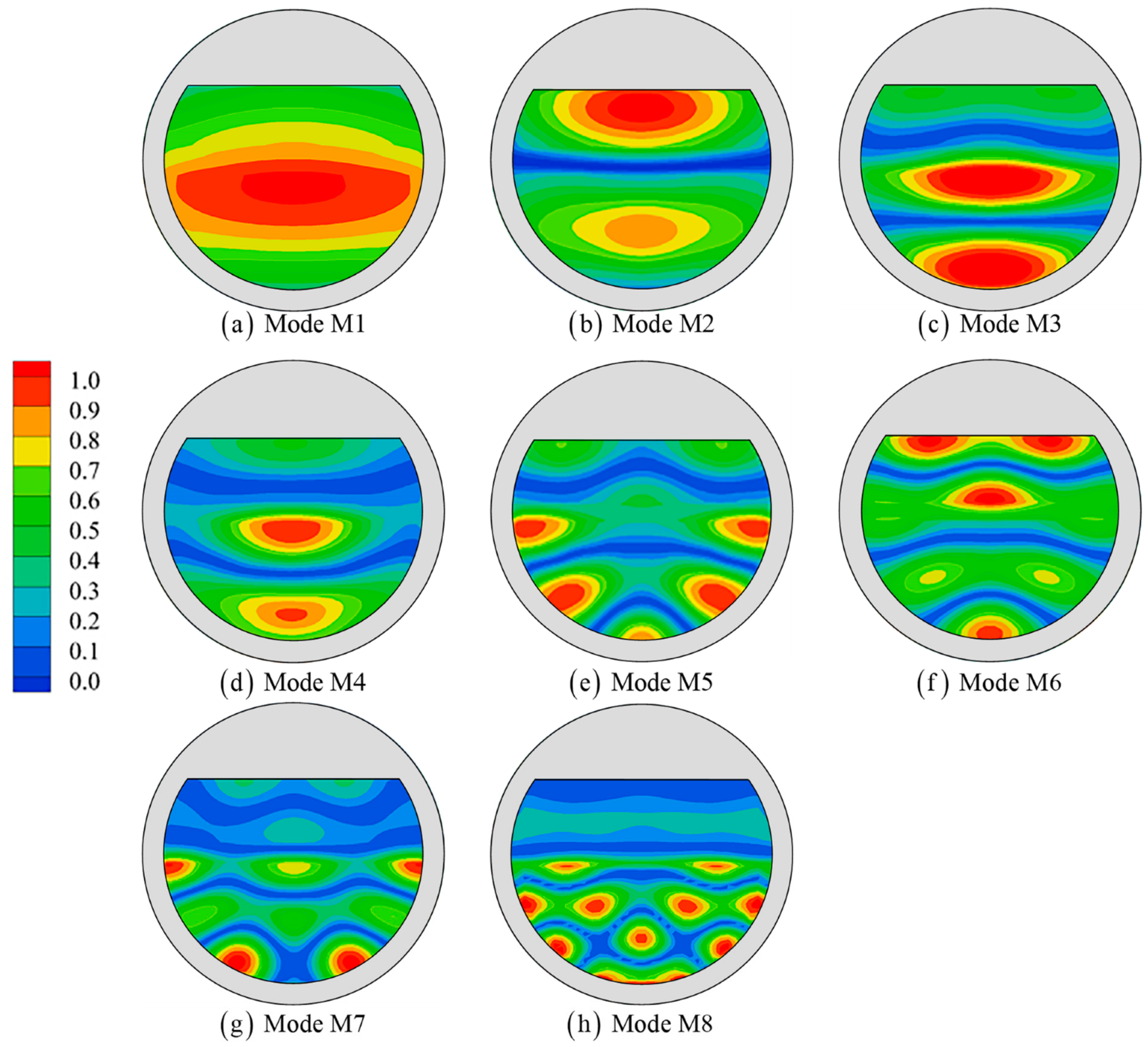
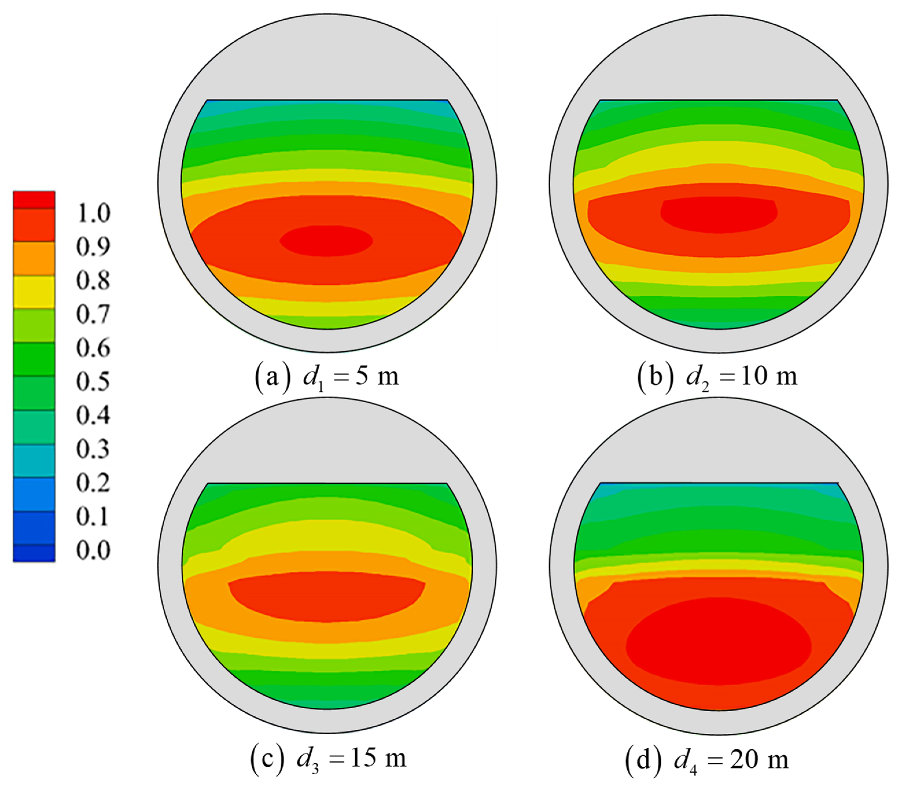
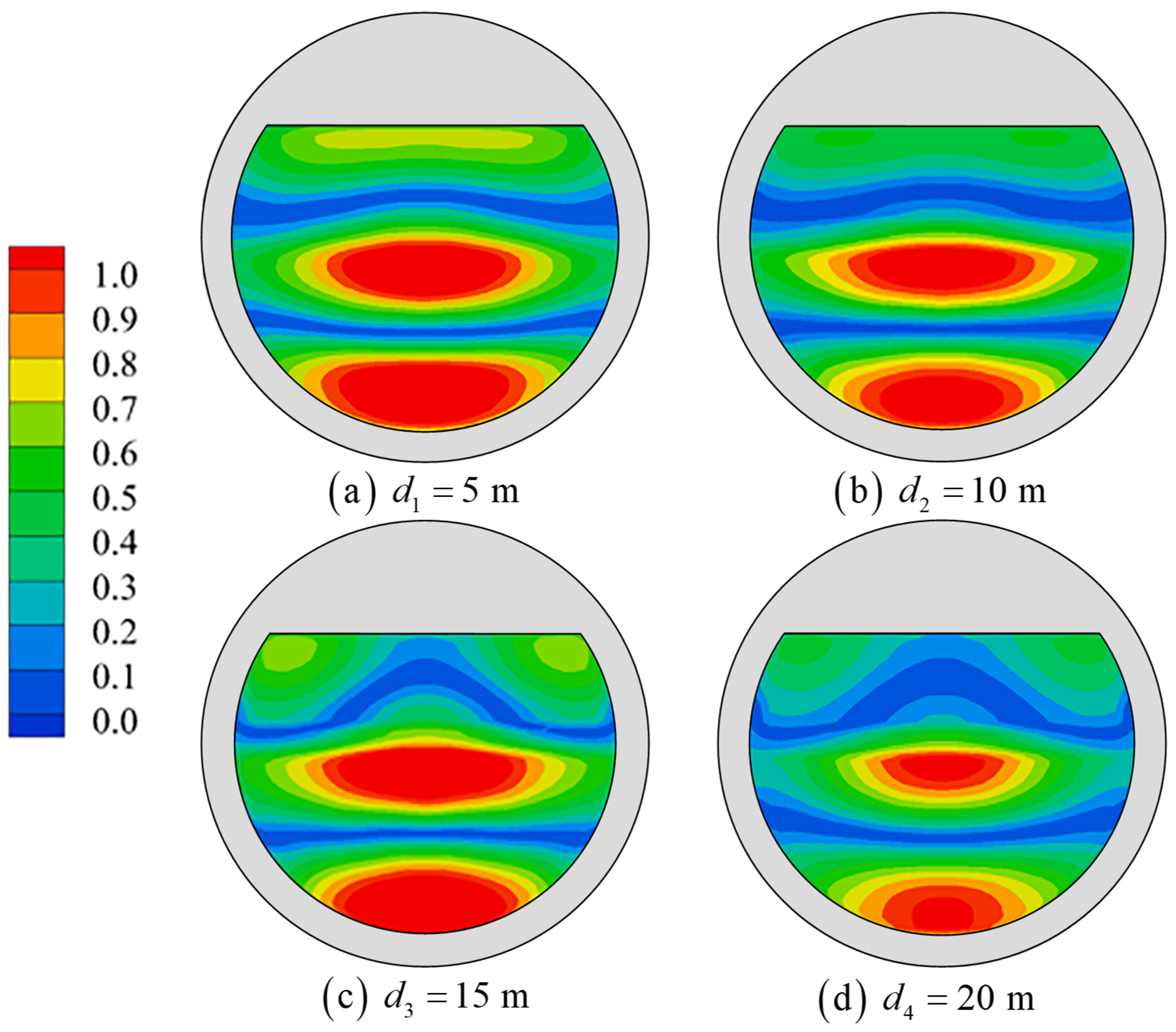
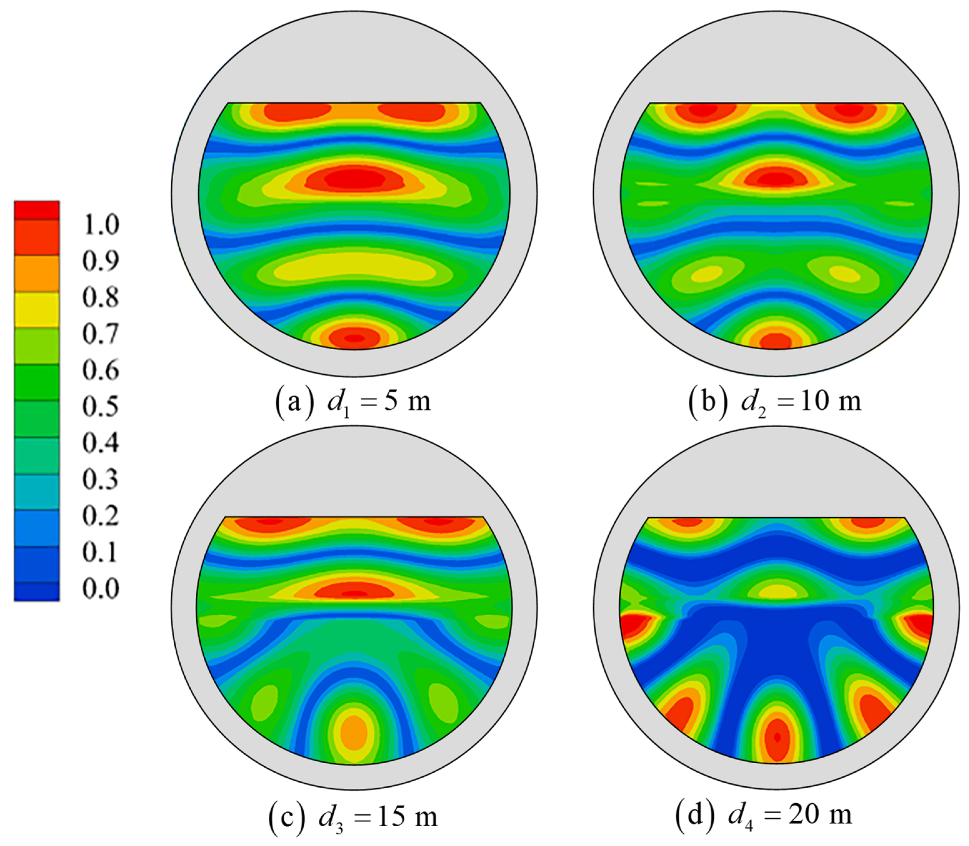
The six resonant mode shapes of the tourist platform are presented in Figure 11. The wave height distributions are normalized by the maximum wave height of each resonant mode. Hence, the color bar is used for all shapes and varies from 0.0 (blue) to 1.0 (red). In mode M1, there is no nodal wave line, and there is a uniform heave of the free surface within the platform; this resonance mode is called the piston mode. In modes M2~M6, the free surface within the platform slosh repeats, which is called the sloshing mode. As the higher-order sloshing modes are excited, the nodal wave lines are curved and show circular modes. From the distribution of the M7 and M8 modes, a wave exists only in half of the inner domain of the platform, and the other half has little water surface rise and fall. This is because the waves corresponding to the M7 and M8 modes dissipate all the energy in the propagation process and cannot form a stable wave field in the whole inner domain of the platform. Therefore, M7 and M8 are not considered resonant modes, and the next study only focuses on the first six modes.
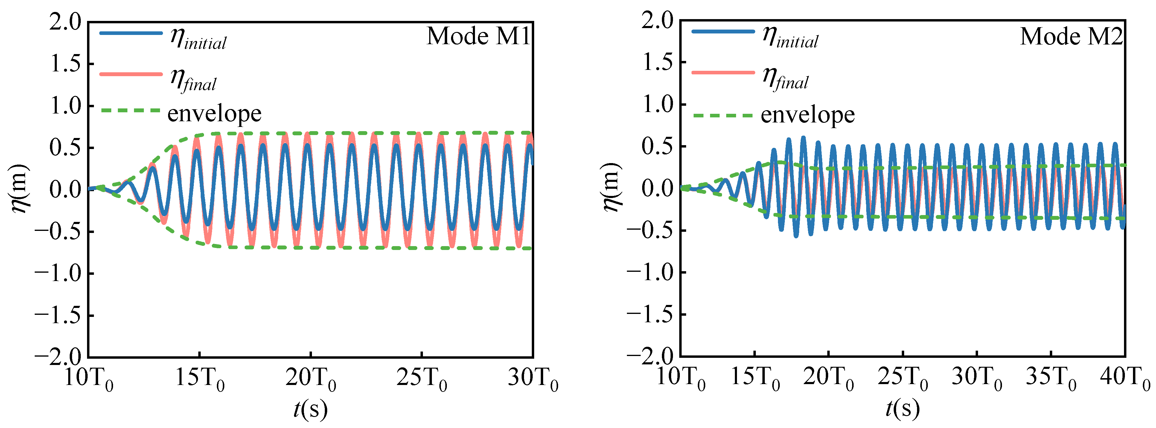
Figure 12 shows the free-surface elevation time histories of WG6 in the inner domain of the platform before and after the resonant frequencies’ wave effect. η i n i t i a l represents the wave surface time history of WG6 without a floating tourist platform in the numerical wave tank. η f i n a l represents the wave surface time history of WG6 after the placement of the floating tourist platform in the numerical wave tank, and the short underline is the envelope of η f i n a l . It can be seen that the slope of the envelope gradually decreases from the M1 mode to the M6 mode, and the time required to form a stable wave field in the inner domain of the floating tourist platform increases. A fixed floating platform is similar to a closed harbor, where wave energy from each period enters the inner domain of the platform through its unique wave energy flux. Long waves have a high wave energy flux, and the corresponding wave motion within the platform can be stabilized quickly, while the opposite is true for short waves.

5. Analysis of Resonance Influencing Factors

The resonance of the water in the inner domain of the floating tourist platform is affected by several factors. The wall thickness of the platform and the distance of the chord from the center of the platform (referred to as the chord distance) affect the resonant frequencies of the water in the inner domain by changing the essential frequencies of the platform itself and the input and output of the wave energy in the inner domain of the platform, resulting in the elevation of the water surface and the resonant modes’ shape change. On the one hand, the change in draft affects the volume of the water in the inner domain of the platform, resulting in a change in the resonant frequencies. On the other hand, it affects the horizontal and vertical wave forces acting on the platform, which, in turn, affects the horizontal and vertical motion of the water in the inner domain. Next, the above three factors are studied and analyzed.
(a)
Influence of the platform’s wall thickness
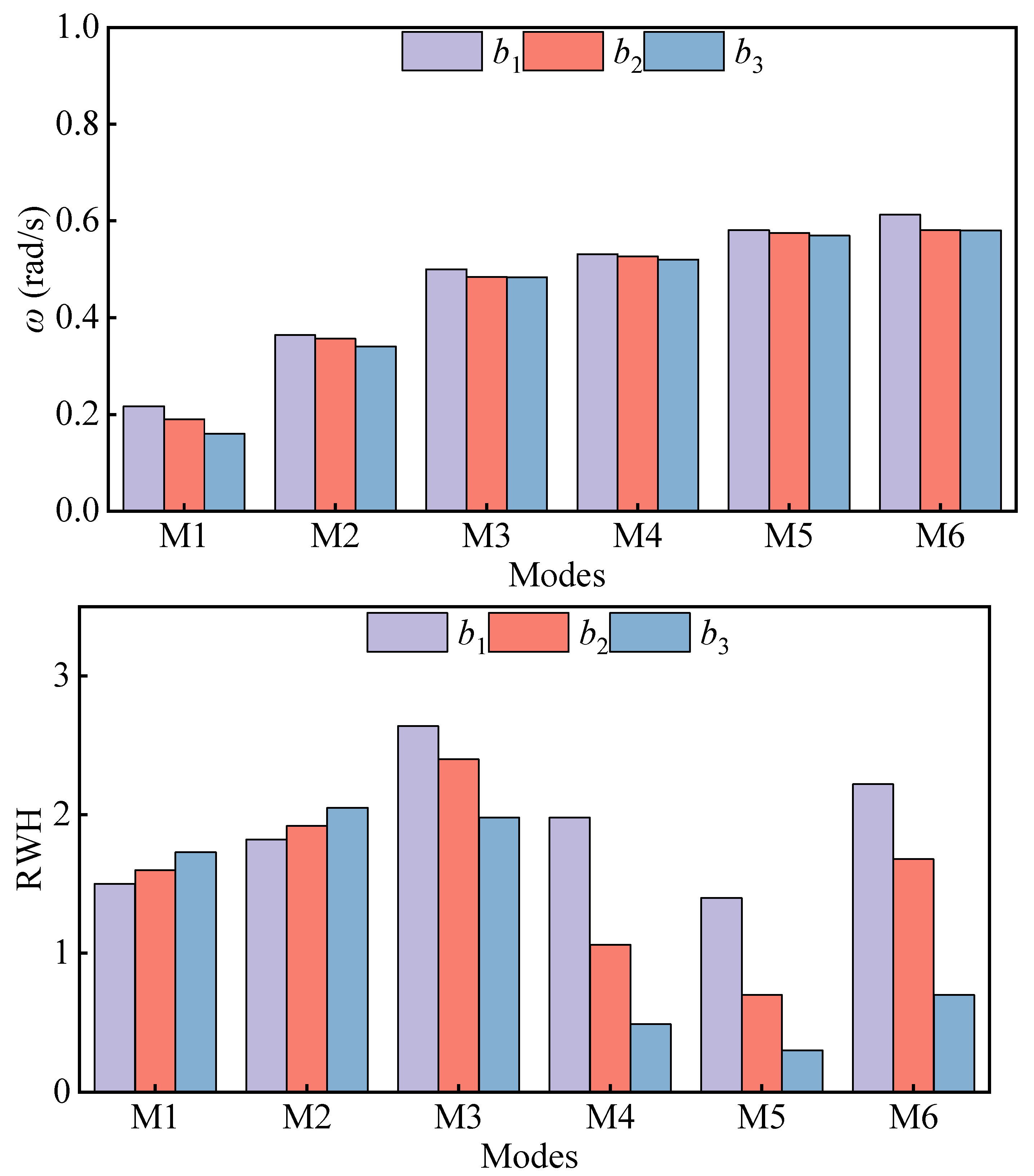
The wall thickness of the floating platform is one element that affects its inner domain water resonance. In order to study the effect of the wall’s thickness on the resonance of the water in the inner domain of the platform, three different cases of wall thicknesses were set up in all three cases, including r = 175   m and the wall thicknesses of b 1 = 25   m , b 2 = 50   m , and b 3 = 100   m . Figure 13 compares the resonant frequencies and co-oscillation amplitudes of water for the different wall thicknesses and MI~M6 modes. With the increase in wall thickness, the resonant frequencies of the M1~M6 modes are reduced, the RWH of the modes M1 (piston mode) and M2 (first-order sloshing mode) increase significantly, and the RWH of the modes M3~M6 decrease. The wall thickness of the floating tour platform is similar to a filter. The lower frequency wave is less affected, and the higher frequencies are more affected by it, and different wall thicknesses correspond to different filtering capacities. The larger the wall thickness, the stronger the filtering ability, where the M1 and M2 modes correspond to the strong penetration ability of the low-frequency wave. The increase in wall thickness will weaken the long-wave energy entering the inner domain of the platform by a small amount while reducing the wave energy flowing out of the inner domain of the platform, resulting in a small increase in total wave energy. The wave energy corresponding to the M3~M6 modes is mostly attenuated, the energy gathered in the inner domain of the platform is reduced, and the value of the co-amplitude of the inner domain water is smaller. Figure 14, Figure 15 and Figure 16 show the representative shape distribution of the M1, M3 and M6 modes with different platform wall thicknesses. As the wall thickness becomes larger, the nodal wave line bending of the three modes occurs, circular characteristics are enhanced, the maximum wave height distribution range shrinks, and the distribution position moves toward the incoming wave direction.
(b)
Influence of the platform chord distance
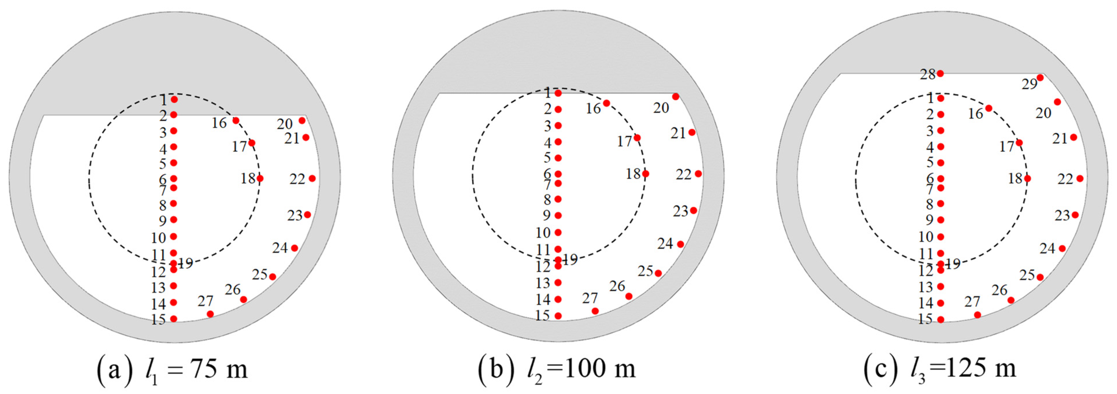
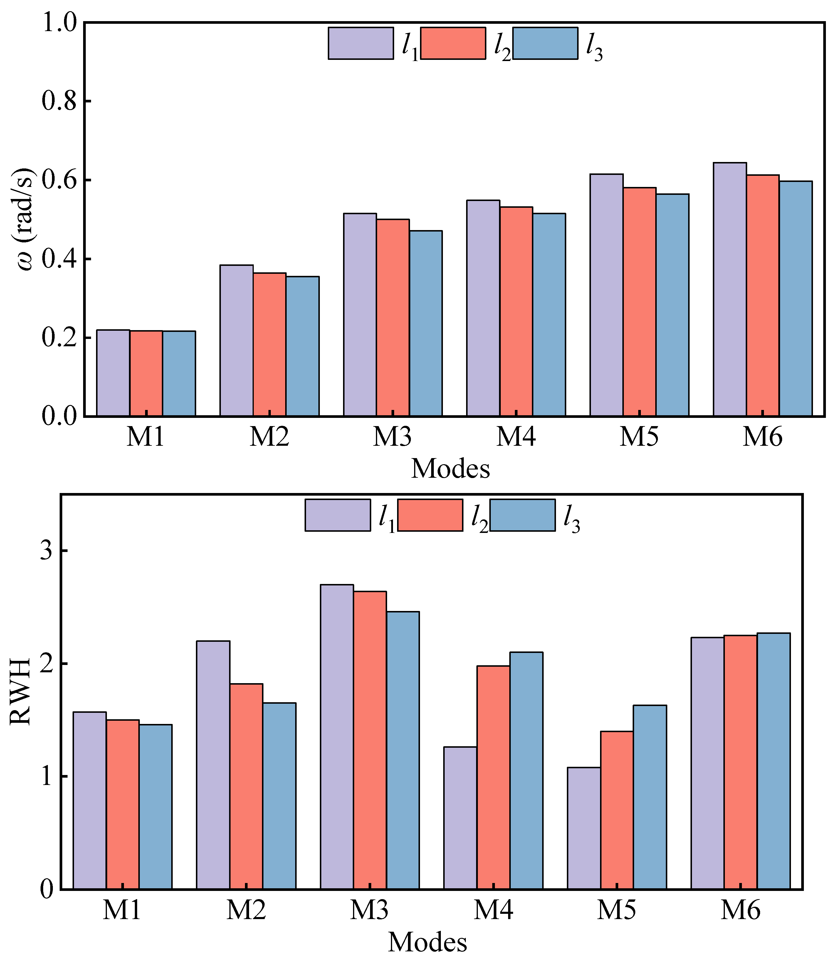
Compared with the inherent wave modes of the traditional closed circular harbor, the water resonance in the inner domain of the floating tourist platform is influenced by the chord in its structure, and the different chord distances will directly change the platform structure and significantly affect the water resonance in the inner domain of the platform. Figure 17 shows the arrangement of wave gauges with three different chord distances. With different chord distances, the position of the wave gauges near the location of the chord varies. Figure 18 shows the resonant frequencies and RWH distribution of the M1~M6 modes when the chord distance l 1 = 75   m , l 2 = 100   m , l 3 = 125   m is calculated for the water resonance in the inner domain of the platform. With the increase of the chord distance, the resonant frequencies of all modes decrease, the RWH of the M1~M3 modes decreases, and the RWH of the M4~M6 modes increases. On the one hand, the existence of a chord is similar to a straight breakwater, where wave energy is reflected and transmitted. The larger the chord distance and the shorter the chord length, the less ability there is to reflect wave energy and more ability to transmit it. On the other hand, the larger the chord distance is, the shape of the floating tourist platform tends to be circular, and the waves inside the platform are easier to focus on one point. The penetration of low-frequency waves is greater; thus, the influence on the M1~M3 mode is greater for the penetration ability of the chord. As the chord distance becomes larger, more wave energy flows out, thus leading to a decrease in the wave energy in the inner domain of the platform and a reduction in the amplitude of the water co-oscillation. For the high-frequency waves with weak penetration, which are influenced by the circular feature of the platform, the larger the chord distance, the easier it is to focus the waves in the inner domain of the platform, and an increase in the amplitude of the water co-oscillation occurs. As shown in Figure 19, Figure 20 and Figure 21, the shape of the M1 mode is less affected by the increase of the chord’s distance, the nodal wave line of the M3 and M6 modes is bent, and the position of the maximum wave height distribution shifts toward the inner wall of the platform.
(c)
Influence of platform drafts
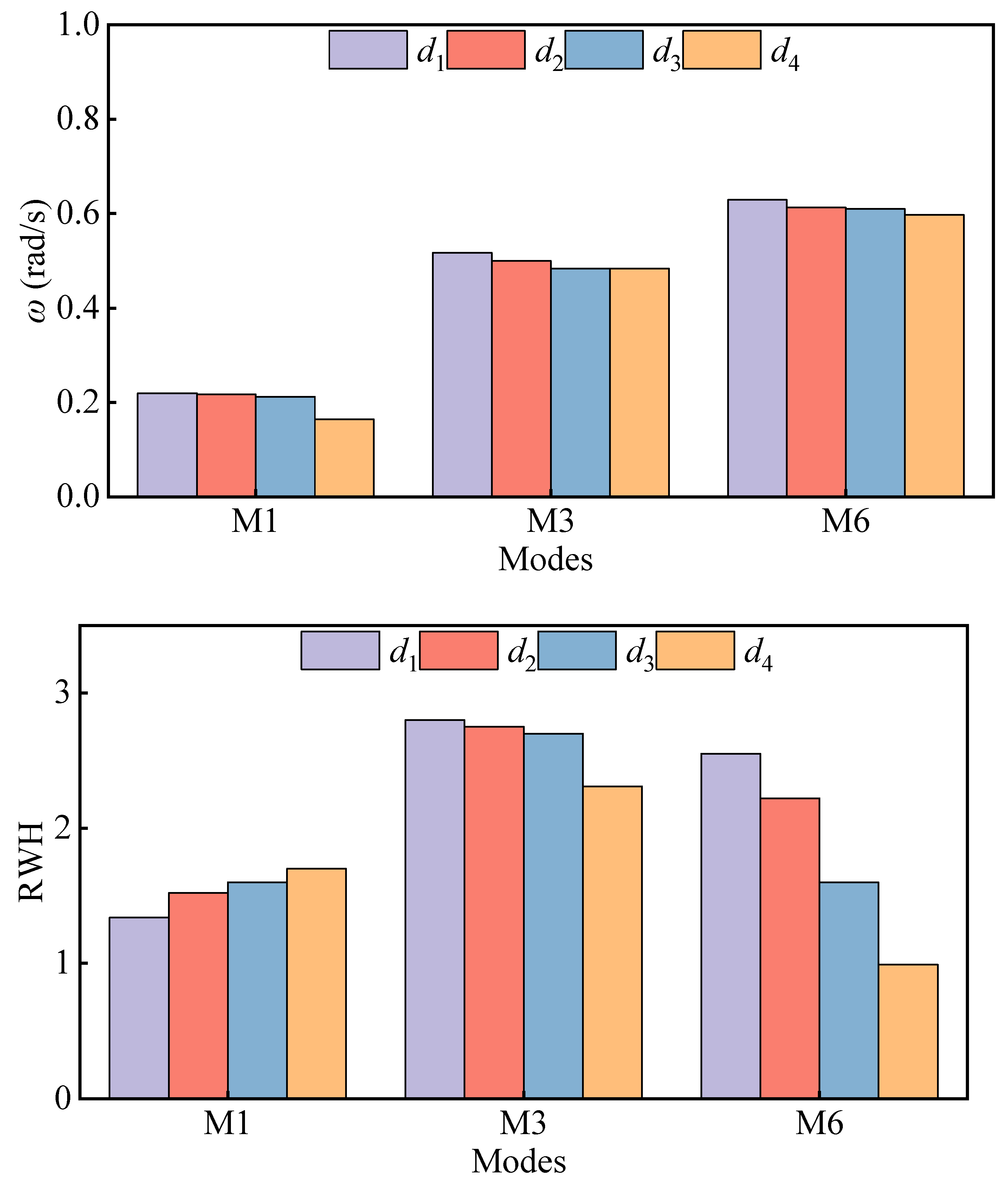
In addition to the mentioned results, the M1, M3 and M6 modes with intense resonance are selected to investigate the effects of drafts on the free-surface elevation of the inner domain of the platform. Four sets of the draft are set for the cases of 5 m, 10 m, 15 m, and 20 m, respectively. The results are shown in Figure 22, where with the increase in draft depth, the resonant frequencies of each mode decrease, the RWH of the M1 piston mode increases, and the RWH of the M3 and M6 sloshing modes decreases. Under the action of the surface wave, the horizontal excitation force of the wave action on the water in the inner domain of the platform increases with the increase of the draft due to the increase of the wet area, and the vertical wave excitation force decreases with the increase of the draft, so the horizontal motion of the water in the inner domain increases and the vertical motion is reduced. Therefore, in the M1 piston mode, the co-oscillation amplitude value becomes larger with the increase of the draft, and in the sloshing modes, the co-oscillation amplitude value decreases with the increase of draft depth. As shown in Figure 23, Figure 24 and Figure 25, the draft increases, the shape of the piston mode M1 has less influence, the sloshing modes of the M3 and M6 nodal wave lines thus bend, and the position of the maximum wave height distribution moves toward the inner wall of the platform.

6. Conclusions

In this paper, first, the accuracy of the 3D non-hydrostatic model in calculating the resonance of the water in the inner domain of a fixed floating platform is verified by comparing the experimental results with the physical model. Next, the resonant frequencies and resonant modes distribution of the inner domain water resonance of the floating tourist platform are studied, and the effects of wall thickness, chord distance and draft on the resonant response of the inner domain water of the platform are investigated. The following conclusions are drawn from the results of this study:
  • The floating tourist platform has six resonant modes, one piston mode, and five sloshing modes, in which higher-order sloshing modes exist. All resonant modes have an RWH > 1 , and the resonance is most obvious when the wave frequency is ω = 0.5   rad / s , and the second-order sloshing mode (M3) is RWH = 2.75 .
  • For a large floating tourist platform, its resonant response is characterized by a wide range of resonant frequency distributions, the piston mode needs to be excited by long-period waves, and the wobble mode can be excited by waves of common frequency in ocean engineering. The largest wave surface elevation among the modes is the second-order sloshing mode, not the piston mode, which differs from the moonpool and harbor oscillations.
  • The wall thickness, chordal distance and draft increase of the floating tourist platform will cause the resonant frequency of each mode to move in the low-frequency direction. The effects on wave surface elevation are different because of the different mechanisms of action of the three, but the effects on the higher-order sloshing modes are greater.

Author Contributions

Conceptualization, X.M. and G.D.; methodology, Z.L., X.M. and G.D.; investigation, Z.L. and Y.M.; resources, J.D., C.T. and S.W.; writing—original draft preparation, Z.L.; writing—review and editing, X.M. and G.D.; visualization, Z.L.; supervision, X.M. and C.A. All authors have read and agreed to the published version of the manuscript.

Funding

This work was financially supported by The Ministry of Industry and Information Technology with the research project ([2019] 357), the National Natural Science Foundation of China (Grant No. 52071060) and the Fundamental Research Funds for the Central Universities (Grant Nos. DUT22LAB101, DUT22RC(6)006).

Institutional Review Board Statement

Not applicable.

Informed Consent Statement

Not applicable.

Data Availability Statement

Data sharing not applicable.

Acknowledgments

The careful reviews by three anonymous reviewers are much appreciated.

Conflicts of Interest

The authors declare no conflict of interest.

References

  1. Ravinthrakumar, S.; Kristiansen, T.; Molin, B.; Ommani, B. Coupled vessel and moonpool responses in regular and irregular waves. Appl. Ocean. Res. 2020, 96, 102010. [Google Scholar] [CrossRef]
  2. Molin, B.; Zhang, X.; Huang, H.; Remy, F. On natural modes in moonpools and gaps in finite depth. J. Fluid Mech. 2018, 840, 530–554. [Google Scholar] [CrossRef]
  3. Molin, B. On the piston and sloshing modes in moonpools. J. Fluid Mech. 2001, 430, 27–50. [Google Scholar] [CrossRef]
  4. Aalbers, A. The water motions in a moonpool. Ocean Eng. 1984, 11, 557–579. [Google Scholar] [CrossRef]
  5. Faltinsen, O.M.; Rognebakke, O.F.; Timokha, A.N. Two-dimensional resonant piston-like sloshing in a moonpool. J. Fluid Mech. 2007, 575, 359–397. [Google Scholar] [CrossRef] [Green Version]
  6. Ravinthrakumar, S.; Kristiansen, T.; Molin, B.; Ommani, B. A two-dimensional numerical and experimental study of piston and sloshing resonance in moonpools with recess. J. Fluid Mech. 2019, 877, 142–166. [Google Scholar] [CrossRef]
  7. Price, W.G.; Magee, A.; Feng, A. Experimental and Numerical Study for Drillship Moonpool Gap Resonances in Stationary and Transit Conditions in Wave Flume. J. Offshore Mech. Arct. Eng. 2020, 142, 021205. [Google Scholar] [CrossRef]
  8. Xu, X.; Zhang, X.; Chu, B.; Huang, H. On natural frequencies of three-dimensional moonpool of vessels in the fixed and free-floating conditions. Ocean Eng. 2020, 195, 106656. [Google Scholar] [CrossRef]
  9. Casulli, V.; Stelling, G.S. Numerical simulation of 3D quasi-hydrostatic, free-surface flows. J. Hydraul. Eng. 1998, 124, 678–686. [Google Scholar] [CrossRef]
  10. Stansby, P.; Zhou, J. Shallow-water flow solver with non-hydrostatic pressure: 2D vertical plane problems. Int. J. Numer. Methods Fluids 1998, 28, 541–563. [Google Scholar] [CrossRef]
  11. Ai, C.; Jin, S.; Lv, B. A new fully non-hydrostatic 3D free surface flow model for water wave motions. Int. J. Numer. Methods Fluids 2011, 66, 1354–1370. [Google Scholar] [CrossRef]
  12. Ai, C.; Ding, W.; Jin, S. A general boundary-fitted 3D non-hydrostatic model for nonlinear focusing wave groups. Ocean Eng. 2014, 89, 134–145. [Google Scholar] [CrossRef]
  13. Ai, C.; Ma, Y.; Yuan, C.; Dong, G. Development and assessment of semi-implicit nonhydrostatic models for surface water waves. Ocean Model. 2019, 144, 101489. [Google Scholar] [CrossRef]
  14. Ma, G.; Shi, F.; Kirby, J.T. Shock-capturing non-hydrostatic model for fully dispersive surface wave processes. Ocean Model. 2012, 43–44, 22–35. [Google Scholar] [CrossRef]
  15. Zijlema, M.; Stelling, G.; Smit, P. SWASH: An operational public domain code for simulating wave fields and rapidly varied flows in coastal waters. Coast. Eng. 2011, 58, 992–1012. [Google Scholar] [CrossRef]
  16. Ai, C.; Jin, S. A multi-layer non-hydrostatic model for wave breaking and run-up. Coast. Eng. 2012, 62, 1–8. [Google Scholar] [CrossRef]
  17. Smit, P.; Zijlema, M.; Stelling, G. Depth-induced wave breaking in a non-hydrostatic, near-shore wave model. Coast. Eng. 2013, 76, 1–16. [Google Scholar] [CrossRef]
  18. Yamazaki, Y.; Kowalik, Z.; Cheung, K.F. Depth-integrated, non-hydrostatic model for wave breaking and run-up. Int. J. Numer. Methods Fluids 2009, 61, 473–497. [Google Scholar] [CrossRef]
  19. Ai, C.; Jin, S. Non-hydrostatic finite volume model for non-linear waves interacting with structures. Comput. Fluids 2010, 39, 2090–2100. [Google Scholar] [CrossRef]
  20. Ai, C.; Ma, Y.; Yuan, C.; Dong, G. A 3D non-hydrostatic model for wave interactions with structures using immersed boundary method. Comput. Fluids 2019, 186, 24–37. [Google Scholar] [CrossRef]
  21. Ai, C.; Ma, Y.; Yuan, C.; Xie, Z.; Dong, G.; Stoesser, T. An efficient 3D non-hydrostatic model for predicting nonlinear wave interactions with fixed floating structures. Ocean Eng. 2022, 248, 110810. [Google Scholar] [CrossRef]
  22. Ai, C.; Ma, Y.; Yuan, C.; Xie, Z.; Dong, G.; Stoesser, T. Vortex shedding and evolution induced by the interactions between a solitary wave and a submerged horizontal plate. J. Hydraul. Res. 2022, 60, 311–325. [Google Scholar] [CrossRef]
  23. Wu, C.H.; Yuan, H. Efficient non-hydrostatic modelling of surface waves interacting with structures. Appl. Math. Model. 2007, 31, 687–699. [Google Scholar] [CrossRef]
  24. Li, C.W.; Zhang, M.L. 3D modelling of hydrodynamics and mixing in a vegetation field under waves. Comput. Fluids 2010, 39, 604–614. [Google Scholar] [CrossRef]
  25. Ma, G.; Kirby, J.T.; Su, S.-F.; Figlus, J.; Shi, F. Numerical study of turbulence and wave damping induced by vegetation canopies. Coast. Eng. 2013, 80, 68–78. [Google Scholar] [CrossRef]
  26. Yamazaki, Y.; Cheung, K.F.; Kowalik, Z. Depth-integrated, non-hydrostatic model with grid nesting for tsunami generation, propagation, and run-up. Int. J. Numer. Methods Fluids 2011, 67, 2081–2107. [Google Scholar] [CrossRef]
  27. Ai, C.; Ma, Y.; Yuan, C.; Dong, G. Semi-implicit non-hydrostatic model for 2D nonlinear wave interaction with a floating/suspended structure. Eur. J. Mech.-B/Fluids 2018, 72, 545–560. [Google Scholar] [CrossRef]
  28. Ma, G.; Farahani, A.A.; Kirby, J.T.; Shi, F. Modeling wave-structure interactions by an immersed boundary method in a σ-coordinate model. Ocean Eng. 2016, 125, 238–247. [Google Scholar] [CrossRef] [Green Version]
  29. Zijlema, M.; Stelling, G.S. Further experiences with computing non-hydrostatic free-surface flows involving water waves. Int. J. Numer. Methods Fluids 2005, 48, 169–197. [Google Scholar] [CrossRef]
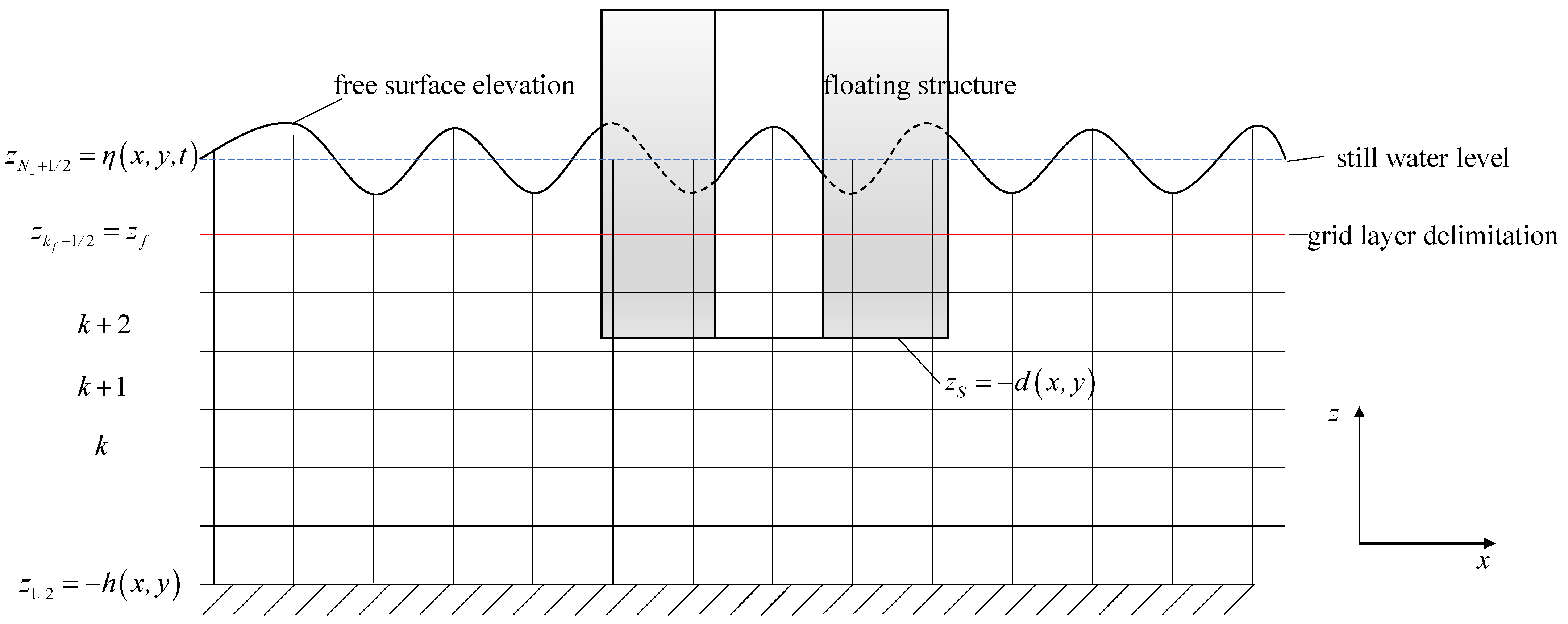
Figure 1. Wave interaction with a fixed floating structure with an internal field.
Jmse 11 00649 g001
Figure 2. Sketch of variables definition.
Jmse 11 00649 g002
Figure 3. The floating tourist platform.
Jmse 11 00649 g003
Figure 4. Schematic of numerical flume and model setup, including the location of water surface elevation measurement stations.
Jmse 11 00649 g004
Figure 5. Free-surface wave height’s time history lines for WG3 in four different grid configurations.
Jmse 11 00649 g005
Figure 6. Comparison of the relative wave heights of WG3 from experimental and numerical calculations.
Jmse 11 00649 g006
Figure 7. Dimension of the floating tourist platform.
Jmse 11 00649 g007
Figure 8. Wave gauges layout.
Jmse 11 00649 g008
Figure 9. Model layout diagram.
Jmse 11 00649 g009
Figure 10. Resonant frequencies and RWH distribution of water in the inner domain of the floating tourist platform.
Jmse 11 00649 g010
Figure 11. Modal shapes of the floating tourist platform.
Jmse 11 00649 g011
Figure 12. The time histories of the wave height of WG6 for different modes shapes.
Jmse 11 00649 g012aJmse 11 00649 g012b
Figure 13. Comparison of resonant frequencies and amplitudes of resonant modes M1~M6 with different wall thicknesses.
Jmse 11 00649 g013
Figure 14. Mode M1 shape with different wall thicknesses.
Jmse 11 00649 g014
Figure 15. Mode M3 shape with different wall thicknesses.
Jmse 11 00649 g015
Figure 16. Mode M6 shape with different wall thicknesses.
Jmse 11 00649 g016
Figure 17. Arrangement of wave gauges with different chord distances.
Jmse 11 00649 g017
Figure 18. Comparison of resonant frequencies and amplitudes of modes M1~M6 with different chord distances.
Jmse 11 00649 g018
Figure 19. Mode M1 shape with different chord distances.
Jmse 11 00649 g019
Figure 20. Mode M3 shape with different chord distances.
Jmse 11 00649 g020
Figure 21. Mode M6 shape with different chord distances.
Jmse 11 00649 g021
Figure 22. Comparison of resonant frequencies and amplitudes of M1, M3 and M6 modes with different drafts.
Jmse 11 00649 g022
Figure 23. Mode M1 shape with different drafts.
Jmse 11 00649 g023
Figure 24. Mode M3 shape with different drafts.
Jmse 11 00649 g024
Figure 25. Mode M6 shape with different drafts.
Jmse 11 00649 g025
Table 1. Grid configurations used in the grid convergence study.
MeshMesh1Mesh2Mesh3Mesh4
Horizontal   grid   size   Δ x = Δ y   ( m ) 0.020.010.010.005
Total   number   of   vertical   layers   N z 24242824
z f   used   in   the   vertical   grid   system   ( m ) −0.16−0.16−0.16−0.16
k f  used in the vertical grid system12121212
Table 2. Resonant frequency and RWH value of each mode.
Mode Frequency   ( rad / s ) Period (s)RWH
M10.21728.951.50
M20.36417.262.15
M30.50012.572.75
M40.53111.831.98
M50.58110.811.90
M60.61310.252.22
M70.6939.071.00
M80.7578.300.80
Disclaimer/Publisher’s Note: The statements, opinions and data contained in all publications are solely those of the individual author(s) and contributor(s) and not of MDPI and/or the editor(s). MDPI and/or the editor(s) disclaim responsibility for any injury to people or property resulting from any ideas, methods, instructions or products referred to in the content.