Article

Experimental Study on CH4 Hydrate Dissociation by the Injection of Hot Water, Brine, and Ionic Liquids

1
Guangzhou Institute of Energy Conversion, Chinese Academy of Sciences, Guangzhou 510640, China
2
CAS Key Laboratory of Gas Hydrate, Guangzhou 510640, China
3
Guangdong Provincial Key Laboratory of New and Renewable Energy Research and Development, Guangzhou 510640, China
4
State Key Laboratory of Natural Gas Hydrate, Beijing 100028, China
5
University of Chinese Academy of Sciences, Beijing 100049, China
*
Authors to whom correspondence should be addressed.
J. Mar. Sci. Eng. 2023, 11(4), 713; https://doi.org/10.3390/jmse11040713
Submission received: 22 February 2023 / Revised: 22 March 2023 / Accepted: 23 March 2023 / Published: 26 March 2023

Abstract

:
Thermal stimulation is an important method to promote gas production and to avoid secondary hydrate formation during hydrate exploitation, but low thermal efficiency hinders its application. In this work, hydrate dissociation was carried out in synthesized hydrate-bearing sediments with 30% hydrate saturation at 6.9 MPa and 9 °C. Ionic liquids, such as 1-butyl-3-methylimidazolium chloride (BMIM-Cl) and tetramethylammonium chloride (TMACl), were injected as heat carriers, and the promotion effects were compared with the injection of hot water and brine. The results showed that the injection of brine and ionic liquids can produce higher thermal efficiencies compared to hot water. Thermodynamic hydrate inhibitors, such as NaCl, BMIM-Cl, and TMACl, were found to impair the stability of CH4 hydrate, which was conducive to hydrate dissociation. By increasing the NaCl concentration from 3.5 to 20 wt%, the thermal efficiency increased from 37.6 to 44.0%, but the thermal efficiencies experienced a fall as the concentration of either BMIM-Cl or TMACl grew from 10 to 20 wt%. In addition, increasing the injection temperature from 30 to 50 °C was found to bring a sharp decrease in thermal efficiency, which was unfavorable for the economics of gas production. Suitable running conditions for ionic liquids injection should control the concentration of ionic liquids under 10 wt% and the injection temperature should be around 10 °C, which is conducive to exerting the weakening effect of ionic liquids on hydrate stability.

1. Introduction

Natural gas hydrate is an ice-like crystalline solid formed by natural gas and water molecules. It has been found to have a huge reserve in deep marine sedimentary strata and permafrost where the temperature is low and the pressure is high [1,2]. A conservative estimation of the natural gas preserved in the form of hydrate ranges from 2.8 × 10¹⁵–8 × 10¹⁸ m3, which is much higher than conventional natural gas, which is about 4.4 × 10¹⁵ m3 [3,4,5]. Methane (CH4) is the most common gas in natural gas hydrate, and 1 volume of hydrate can contain up to 164 volumes of natural gas [6]. Therefore, natural gas hydrate is known as a potential clean energy and has been intensively investigated in earth science and energy research. Because of the high energy density of natural gas hydrates and the large amount of carbon trapped in natural gas hydrates, the dissociation of natural gas hydrates is considered a potential threat associated with global warming. The amount of CH4 released by hydrate dissociation is typically in the range of 5 million tons per year, but CH4 is 20–30 times more potent as a greenhouse gas than CO2, thereby increasing global warming [7,8]. Even if CH4 is released during hydrate dissociation, there may be very few places where gas hydrate dissociation releases significant amounts of CH4 into the atmosphere depending on several factors, such as the depth of gas hydrate in the sediment, the strong sediment and water column sinks, and the inability of bubbles emitted at the seafloor to deliver methane to the sea–air interface in most cases. Furthermore, there is no conclusive proof that hydrate-derived methane reaches the atmosphere. At the current level of technology, gas hydrate exploitation is slow and therefore does not have a huge impact on the marine ecosystem or the atmosphere. Problems, such as submarine landslides, may occur, but these can be avoided as much as possible when designing production plans. Overall, natural gas hydrate development is safe [9,10].
At present, hydrate exploitation technology has not reached a commercial scale, and at least four kinds of gas production methods have been developed, including depressurization, thermal stimulation, chemical injection, and CO2 replacement [11,12,13]. Most of these methods recover natural gas by in situ hydrate dissociation where the ambient pressure is reduced below the hydrate equilibrium pressure (depressurization method) or the ambient temperature is enhanced above the hydrate equilibrium temperature (thermal stimulation method). The depressurization method is considered the most efficient and economical method for gas production because its recovery does not require additional energy or chemical input [14]. However, if the pressure transfer is limited in the hydrate-bearing layer, thermal stimulation and chemical injection can be suitable alternatives [15,16].
Thermal stimulation and chemical injection are often employed in combination with the depressurization method to avoid huge energy loss. After decades of development, the thermal stimulation method has been further divided into hot fluid injection, electric heating injection, and microwave heating [17,18]. Hot fluid injection is the most practical method. Li et al. [19] measured hydrate dissociation by hot water injection and found that heat loss during the hot water injection stage was evident and that heat convection dominated the heat transfer. Feng et al. [20] further studied the thermal stimulation method in a five-point well system and found that shorter production times are associated with higher heat injection rates, but water injection rates have no impact on gas production. To resolve the low efficiency of thermal injection production, Chen et al. [21] proposed a hydrate-based warm brine preparation method and found that the heating coefficient of the warm brine preparation reaches 3.0 and gas production performs better with higher salinity and temperature. Li et al. [22] studied the influence of initial hydrate saturation on gas production and found the optimum hydrate saturation is around 48%, and that gas production is limited as hydrate saturation surpasses 64%. These findings suggest that enhancing heat and mass transfer is the key to improving energy efficiency.
Injection of thermodynamic inhibitors, such as methanol and glycol, is another way to improve the thermal efficiency of thermal stimulation [23,24,25]. Li et al. [26] studied the dissociation of CH4 hydrate in the presence of methanol and found that the hydrate dissociation rate of hydrate was proportional to inhibitor concentration and injection rate. Dong et al. [27] studied the dissociation of propane hydrate by methanol and ethylene glycol injection and found that the presence of alcohols accelerates gas hydrate dissociation and reduces the total need of external energy to dissociate the hydrates. The findings suggest that the hydrate dissociation time decreased with an increase in the concentration of inhibitors, although the degree of reduction was weakened. However, large-scale injections of alcohols have been reported to cause a risk of pollution of the oceanic environment, so ionic liquids have been proposed as a new type of thermodynamic hydrate inhibitor [28]. Xiao et al. [29] found that ionic liquids have both thermodynamic and kinetic inhibition effects on hydrate. Therefore, ionic liquids are suggested to reduce the water activity in the host lattice of hydrate and are used as plugging agents in pipeline transportation [30,31,32]. Yu et al. [33] measured hydrate dissociation using ionic liquids and found that 2.0 g/L BMIM-Cl was found to have the best performance, as hydrate dissociation was only 60 min and therefore 86% faster than without plugging removers. However, the promotion effect of ionic liquids on gas production by thermal stimulation has not been investigated.
To better understand the effects of ionic liquids on gas production, 1-butyl-3-methylimidazolium chloride (BMIM-Cl) and tetramethylammonium chloride (TMACl) were used to stimulate gas production in hydrate-bearing sediments. The performances were compared with the injection of hot water and brine. The hydrate-bearing sediments were 6.9 MPa and 9 °C with 30% hydrate saturation. The effects of injection temperature, concentration, and volume of injection on gas production and thermal efficiency were analyzed. The results will provide suitable solutions for thermal stimulation by ionic liquids.

2. Experimental Section

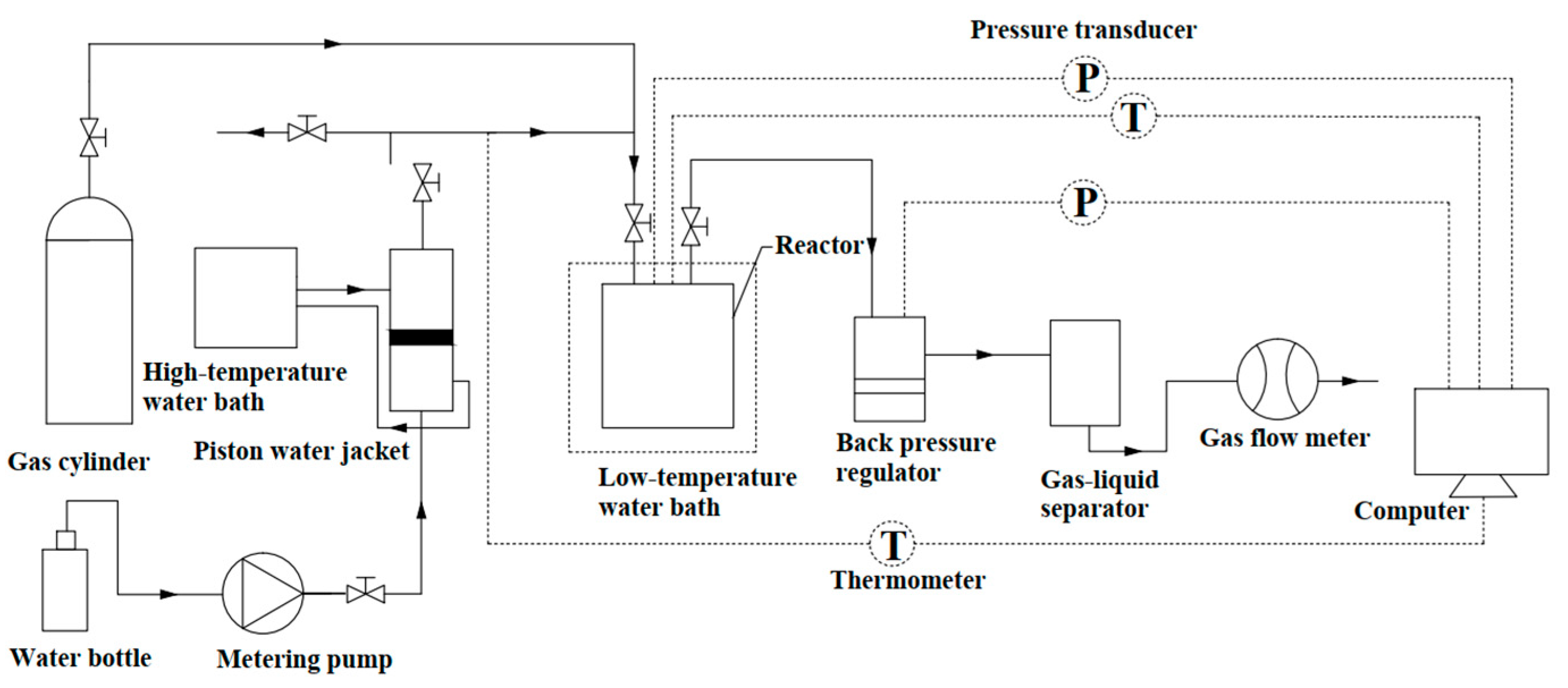
2.1. Apparatus and Materials

The gas production measurements were carried out in a high-pressure cylinder 50 mm in diameter and 50 mm in length. A PTFE bushing with a diameter of 49 mm, a height of 43.5 mm, and a thickness of 4 mm was used to hold the hydrate-bearing sediments. Two thermal resistances (Beijing West AVIC Co., Ltd., Beijing, China, PT100, 223.15–473.15 K, ±0.1 K) were inserted from the top of the cylinder, which were used to measure the temperature in gas and sediments, respectively. There was a pressure sensor (Beijing West AVIC Co., Ltd., CYB-20, 0–20 MPa, ±1 MPa) at the top of the reactor to monitor the pressure change in the reactor. A stainless steel pipe that was 3 mm in diameter was inserted along the axis of the cylinder, which was used to simulate the production well. The cylinder was equipped with an injection system that comprised a water bottle, an advection pump (Shanghai Wufeng Instrument Co., Ltd., Shanghai, China, LC-P100, 0–21 MPa, 0–9.999 mL/min, accuracy: ±0.001 mL/min), and a piston water jacket, as seen in Figure 1. The cooling jacket was connected to the high-temperature thermostatic bath (Ningbo Tianheng Co., Ltd., Ningbo, China, THGD1020) for heat exchange to maintain the constant temperature of the injected hot water. The water bottle was injected into the bottom of the water jacket through the advection pump, pushing the piston inside the water jacket to move upward, and the hot water was pushed into the reactor. The gas collection system was composed of a back pressure valve (OSK, Beijing, 15–2500 psig, 250.15–373.15 K, accuracy: ±0.001 MPa) and a wet gas flow meter (Changchun Alpha Instrument Co., Ltd., Changchun, China, LMF-1, accuracy: ±1%). The data acquisition unit recorded the pressure and temperature as they varied over time.
The materials used in this work are listed in Table 1. Methane (CH4) used in this work was provided by Guangzhou Yuejia Gas Co., Ltd., Guangzhou, China, with a purity of 99.5%. The pore water (H2O) in sediments was distilled water made in the laboratory, and 1-butyl-3-methylimidazolium chloride (BMIM-Cl) and tetramethylammonium chloride (TMACl) were supplied by TCI (Shanghai) Chemical Industry Development Co., Ltd., Shanghai, China. Brine was prepared in the lab using sodium chloride (NaCl). The sediment used in this work was natural sand collected from the Pearl River Estuary, which was 0.25–0.425 mm. Rinsing and drying of sand was performed to reduce the effect of dust and impurities on the experiment. The porosity was 40% and the apparent density was 1.6 g/cm3.

2.2. Procedure

The experiment began with the preparation of hydrate-bearing sediments, followed by the gas production measurement. In the hydrate preparation stage, 44 g natural sand and 6 g distilled water were mixed evenly and densely packed in the cylindrical mold made of PTFE bushing. Then, the reactor was sealed, evacuated, and immersed in the thermostatic bath maintained at 2 °C. As the temperature in the cylinder was stable, 11 MPa CH4 was loaded into the cylinder to form hydrate. Hydrate formation was carried out in an isochoric system so that the gas consumed for hydrate growth could be reflected by the pressure decrease in the cylinder. The amount of CH4 consumption could be calculated by P-R equation of state. The hydration number of CH4 hydrate was assigned to 6.0 and the density was set as 0.925 g/cm3; then, the volume of the formed CH4 hydrate could be calculated [34]. The hydrate saturation was defined as the volume ratio of CH4 hydrate and pores in the sediment. When the hydrate saturation reached 30%, the sediment temperature and pressure were adjusted to 9 °C and 6.9 MPa, such that the thermodynamic conditions were just enough to keep the CH4 hydrate stable. As the pressure and temperature reached stability, the preparation of the hydrate-bearing sediment was complete.
The gas production stage was further divided into 3 steps: thermal injection, soaking, and gas production steps [35,36,37]. In the thermal injection step, the advection pump injected the hot liquid into the cylinder at a rate of 10.0 mL/min for a certain period of time. To safely inject water into the cylinder, the production well was opened and the pressure during injection was kept near 6.9 MPa, which was kept constant by a back pressure regulator. After that, the system was soaked for 6 min and the injected hot liquid was allowed to penetrate around the reservoir, as seen in Figure 2. At last, the valve was opened so that the CH4 released from hydrate dissociation could be vented from the production well. When the instantaneous flow was 0 mL/min, the test was stopped, all valves were closed, and the data were saved. Finally, the pressure was set the back to 0.1 MPa to release the residual gas in the reactor.

2.3. Calculation of Hydrate Saturation and Thermal Efficiency

2.3.1. Calculation of Hydrate Saturation

The hydrate saturation S h is defined as the ratio of the volume of hydrate V h to the pore volume V k .
S h = V h V k
During the experiment, assuming that the skeletal structure of the sediment is almost incompressible and that methane hydrate is generated uniformly in the pore space, the volume of hydrate can be calculated from the molar amount of methane gas consumed during hydrate generation. Based on the P-T data of the hydrate generation process collected by the data acquisition system, we can obtain:
Δ n = V g a s P z R T i n i P z R T e n d
where Δ n is the amount of methane hydrate produced in the sediment, mol; V g a s is the volume of free gas in the reactor, m3; R is the gas constant, taken as 8.3145 J · mol−1 · K; and z is the compression factor, which can be obtained by iterative calculation using MATLAB based on the modified Peng–Robinson equation of state.
The volume V h of the hydrate in the sediment can be determined as:
V h = Δ n × M h ρ h
where M h is the molar mass of hydrate, g/mol. According to the relevant literature, the hydrate number is taken as 6, so the hydrate molar mass is 124 g/mol. ρ h is hydrate density, 0.925 g/cm3.

2.3.2. Calculation of Thermal Efficiency

Thermal efficiency describes the proportion of heat adsorbed by CH4 hydrate for dissociation in the total injected heat, which is an important parameter to evaluate the economics of thermal stimulation. According to the literature, the thermal efficiency η can be written as follows [18,38,39]:
η = Q t · M g a s C w · M w · T 0 T
where Mw is the amount of the injected hot fluids; T0 is the well head temperature; T is the temperature of the hydrate-bearing sediment before the injection of hot fluids; Mgas = 37.6 MJ/m3 is the heat release of methane combustion; and Cw = 4.2 ×10³ J/(kg K) is the specific heat of water. Therefore, the unit of the energy efficiency is 1.

3. Results and Discussion

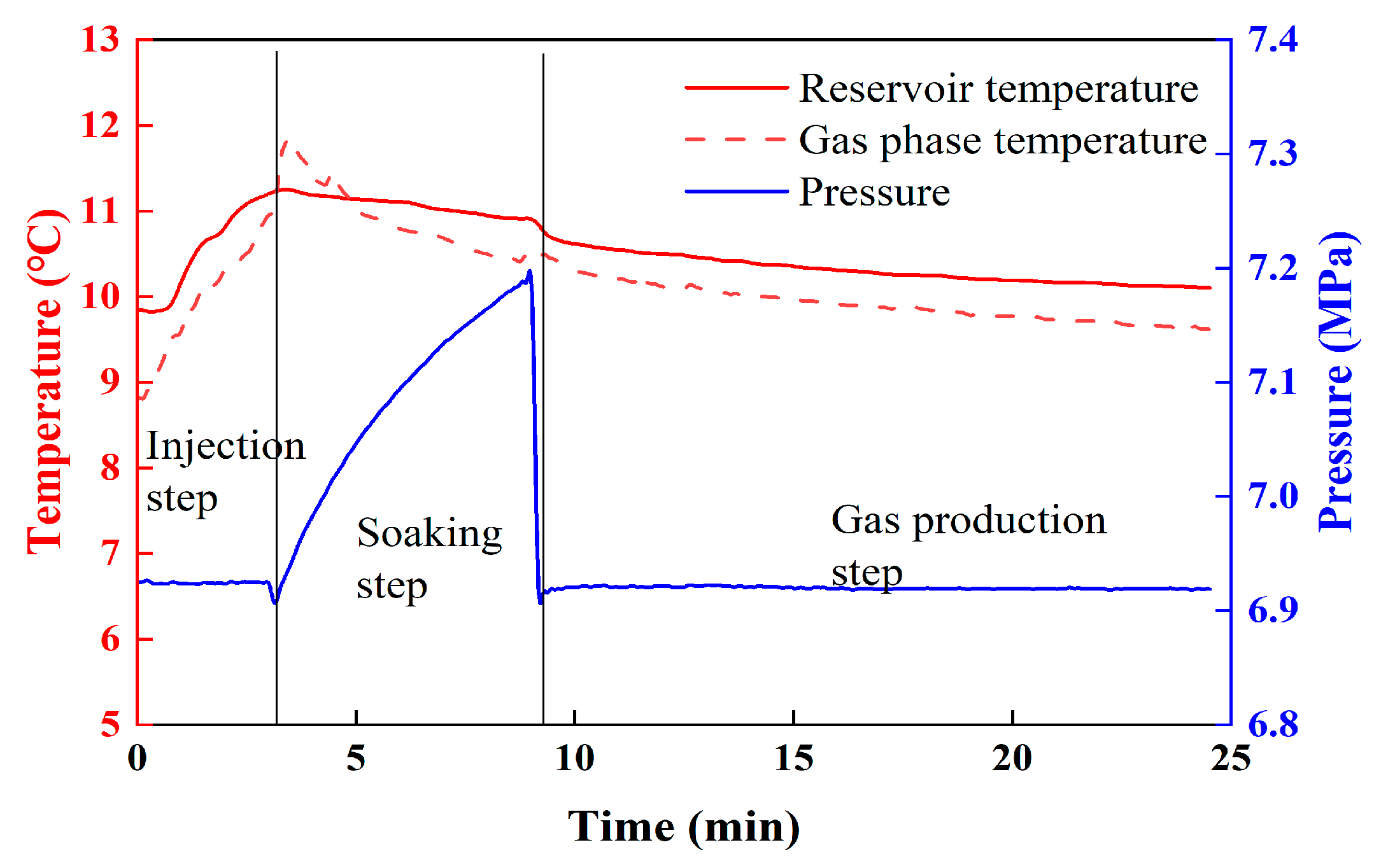
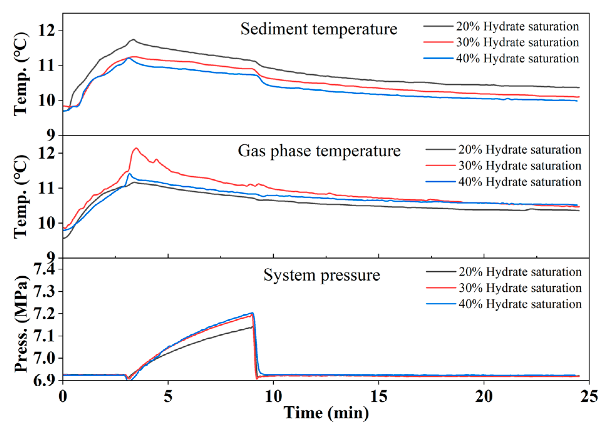
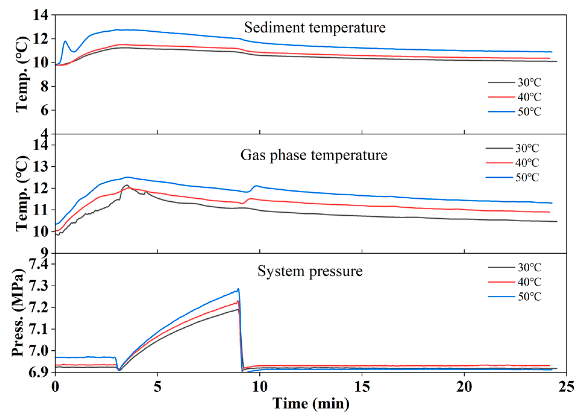
3.1. Gas Production by Hot Water Injection

We first conducted hot water injection experiments. In order to test the feasibility of experimental methods and devices from different perspectives, we studied the effects of heat injection parameters (heat injection volume and heat injection temperature) and geological parameters (hydrate saturation) on hydrate exploitation. The initial conditions of each experiment are listed in Table 2.
The effects of the amount of injected hot water on gas production were investigated in Exp. 1–3, and the temperature and pressure profiles can be seen in Figure 3. As the injected hot water increased from 30 to 40 mL, the sediment temperature increased quickly in the injection step and kept relatively constant by 1–2 °C above the initial temperature in the soaking step. However, the amount of injected hot water was not found to have an evident influence on sediment temperature, as seen in Figure 3. The influence of water injection on the temperature of the gas phase was found to be evident in the soaking step. The gas phase temperature was found to rise sharply at the beginning of the soaking step as the hot water injection reached 35 and 40 mL. The pressure rise was also observed in the soaking step, as seen in Figure 3. The pressure increased by 0.3–0.45 MPa as the hot water injection increased from 30 to 40 mL, suggesting that increasing the amount of hot water injection was beneficial to enhancing gas production. When the injection volume was increased from 35 mL to 40 mL, we discovered that gas production actually dropped. This is due to the fact that the water volume in the cell increased and the water output in the experiment could not be discharged due to the restriction of the experimental setup, which resulted in a thicker water layer in the reactor at the later stage of injection. The additional 5 mL of water was mostly used to heat the reactor’s free water and decomposition gas. Moreover, the reactor’s empty area after sand loading was 49 mL, meaning that less water could be injected into it (5 mm between the PTFE and the reactor). When the injection volume was 40 mL, the water layer had reached the top of the reactor and the gas production well was surrounded by water, making it more difficult for the gas to penetrate the thick water layer to reach the gas production well, resulting in a lower collected gas production volume.
Investigations of the effect of initial water saturation on gas production were carried out in Exp. 1, 4, and 5, where the initial hydrate saturations varied from 20–40%. The results showed that higher initial hydrate saturation reduced the temperature rise of sediments during the injection and soaking step, but the pressure rise was found to be more evident, as seen in Figure 4, suggesting that more injected heat had been adsorbed by hydrates [40]. Therefore, gas production and thermal efficiency were also found to increase from 0.352 L, 33.1% up to 0.404 L, 38.4% as the initial hydrate saturation increased from 20 to 40%.
The effect of injected hot water temperature was investigated in Exp. 1, 6, and 7, where the hot water temperatures were 30, 40, and 50 °C, respectively. It could be seen that the temperature rise in sediments increased by 1.3, 1.7, and 2.8 °C, respectively, as seen in Figure 5; these increases were higher than simply increasing the volume of injected water. However, the pressure rise during the soaking step was not found to evidently enhance gas production, suggesting that the injected heat was not adsorbed by hydrates [41]. Although gas production was increased from 0.392 to 0.488 L, the thermal efficiency reduced from 37.3 to 23.6%.
Judging from the experimental results, increasing the amount of injected hot water was beneficial for increasing the total CH4 production and thermal efficiency. The sediments with higher initial hydrate saturation were also good for promoting gas production, however, when the hydrate saturation increases from 30% to 40%, the gas production only increases by 3.1%, indicating that the higher the saturation, the higher the permeability, which is instead unfavorable to the injection of thermally decomposed methane hydrate Elevating the injected hot water temperature was not found to bring about higher gas production compared to increasing the hot water, and the thermal efficiency dropped significantly. Therefore, increasing the amount of injected hot water in the sediments with higher hydrate saturation is a wise choice for gas production by hot water injection.
According to the analysis above, higher heat injection temperatures result in higher gas production volumes but lower thermal efficiencies; conversely, higher hydrate saturation levels result in higher gas production volumes and higher thermal efficiencies, all of which are in accordance with earlier studies [42,43,44]. However, there is a slight difference in the volume of heat injection. To eliminate the risk that the decomposition gas could not be discharged smoothly due to excessive water injection, we only injected 30 mL in the subsequent experiments.

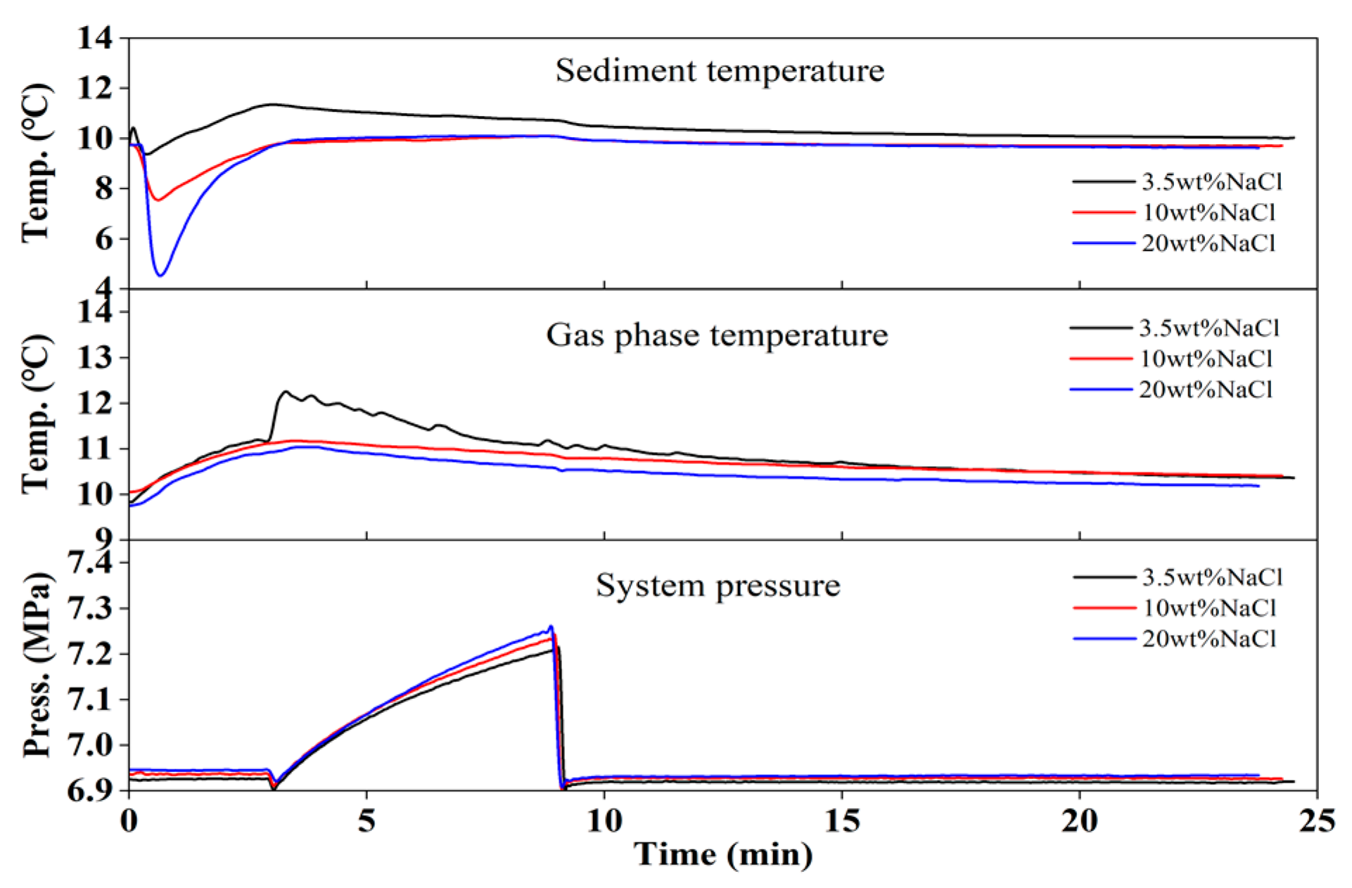
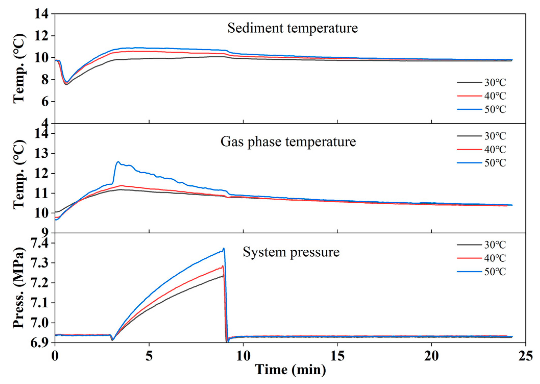
3.2. Gas Production by Hot Brine Injection

To test the influence of working fluid on thermal stimulation, the brine with 3.5 wt% NaCl was used as the heat carrier. The experimental conditions are listed in Table 3. The effects of salt concentration and brine temperature on gas production were measured. The initial hydrate saturation was fixed at 30% and the injection volume was controlled at 30 mL in each experiment.
Because the specific heat of brine is lower than pure water, the heat used to heat the sediment decreased when the injection volume of brine was the same as that of the hot water. However, the hydrate dissociation seemed to become stronger when the NaCl increased from 3.5 to 20 wt%, as seen in Exp. 8–10. The temperature in the sediment sharply decreased once the brine was injected and then rose back up during the injection step, as seen in Figure 6. Because NaCl is a thermodynamic hydrate inhibitor that impairs the stability of CH4 hydrates, the injection of brine was suggested to induce the hydrate dissociation, leading to the heat adsorption in the sediment [45]. The dissociation of CH4 hydrate may be reflected by the pressure rise in the soaking step where the pressure increased by 0.3–0.35 MPa, as seen in Figure 6. However, such an increase was not found to be higher than the increase caused by the hot water injection by varying the injection volume. The thermal efficiencies were also equal to those obtained by hot water injection. In this case, increasing the NaCl could bring a rise in gas production and thermal efficiency, but the effect was not significant.
In Exp. 8, 11, and 12 (Table 3), the effect of brine temperature was measured by varying the brine temperature from 30 to 50 °C. The sharp decrease in sediment temperature can also be observed in Figure 7. The pressure increased by 0.3, 0.36, and 0.46 MPa as the initial brine temperature was 30, 40, and 50 °C, respectively. By increasing the temperature from 30 to 50 °C, gas production increased by 33.8%. The thermal efficiencies were also found to drop from 42.7 to 25.2% as the temperature increased.
Comparing the hot water injection and brine injection, the sediment temperature after brine injection was found to drop instead of increasing, but the addition of NaCl was not expected to dramatically enhance gas production and thermal efficiency, suggesting that the promotion effect of brine was limited.

3.3. Gas Production and the Injection of Ionic Liquids

To provide a comprehensive understanding of injecting ionic liquids on CH4 production, BMIM-Cl and TMACl were selected for the experiments. To compare the results from hot water injection and brine injection, the initial hydrate saturation was fixed at 30% and the injection volume was controlled at 30 mL in each experiment. The effect of salt concentration and the temperature of ionic liquids on gas production were measured.

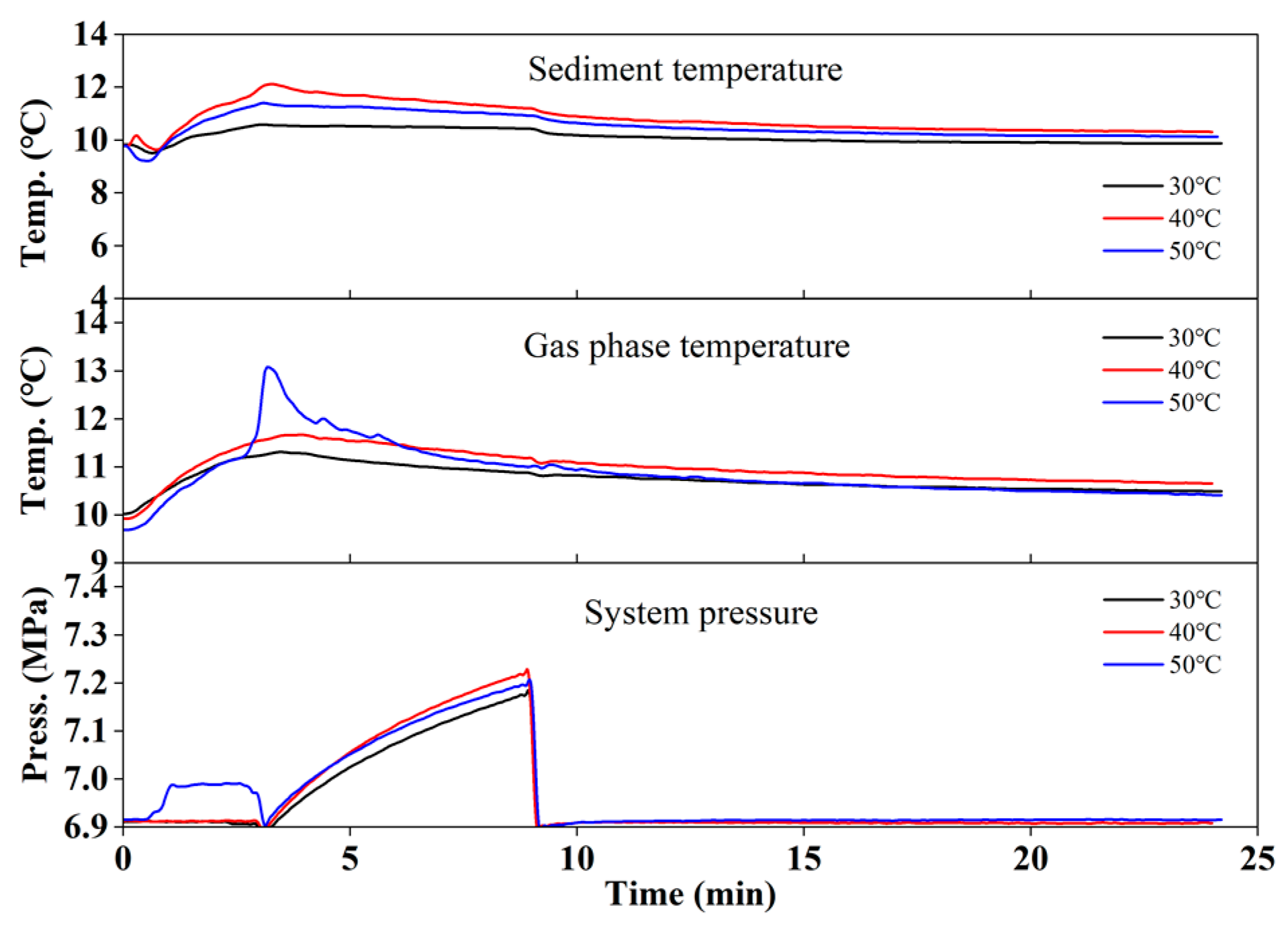
3.3.1. BMIM-Cl Injection

The dissociation of CH4 hydrate in the sediment at different BMIM-Cl concentrations and heat injection temperatures was studied. Gas production is shown in Table 4. The experiment adopted the controlled variable method, and experiment 13 was the control experiment. The initial hydrate saturation was fixed at 30% and the injection volume was controlled at 30 mL in each experiment.
When BMIM-Cl solution was injected, the temperature in the hydrate-bearing sediments dropped quickly, which was quite similar to the profile observed in brine injections. It should be noted that the temperature rise in the gas phase evidently increased, as seen in Figure 8, suggesting that more heat was used to warm the gas phase rather than the sediments. Therefore, the pressure rise during the soaking step was slight and did not surpass 0.35 MPa.
Because the temperature rise in the gas phase occupied a large portion of the heat in the injected ionic liquids, the heat used for hydrate dissociation was reduced. However, gas production was found to be higher than in brine injection (Exp. 8, 9, and 10). The BMIM-Cl was suggested to impair the stability of hydrates, which was similar to the function of NaCl [46]. The thermal efficiency approached 50% as the BMIM-Cl increased up to 30 wt%.
Increasing the injection temperature was not found to be a good choice to enhance the thermal efficiency. As the sediment temperature increased from 30 to 50 °C, the initial drop of the sediment temperature became smaller, and then a large increase could be seen. The initial temperature drop was assumed to be induced by the hydrate dissociation, while the subsequent temperature rise should be ascribed to the apparent heat brought on by the ionic liquids. However, the pressure increase during the soaking step was not found to largely enhance gas production. The largest pressure increase was only about 0.3 MPa, as seen in Figure 9, suggesting that the ionic liquids did not penetrate to a larger domain.
In view of the gas production in Table 4, the amount of recovered CH4 was reduced from 0.456 to 0.352 when the injection temperature increased from 30 to 50 °C. The thermal efficiency was also reduced from 43.8 to 16.8%, which was even lower than thermal efficiency related to hot water injection under the same initial conditions. The heat adsorption from the gas phase was found to reduce the heat for hydrate dissociation. BMIM-Cl was also found to retard the hydrate dissociation.

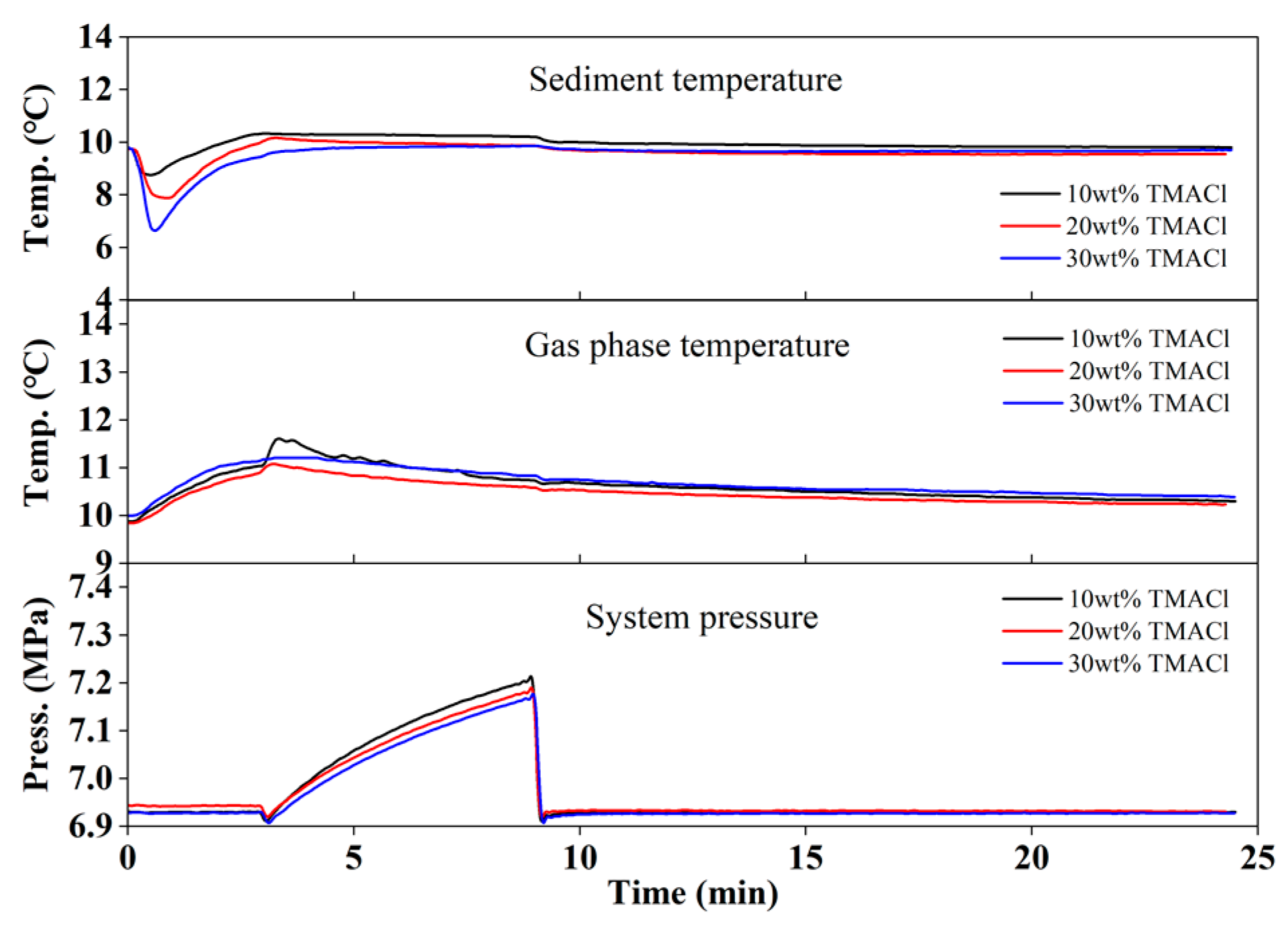
3.3.2. TMACl Injection

To study the effect of TMACl injection on hydrate dissociation, experiments were conducted at different concentrations and injection temperatures. The details of the experiments are shown in Table 5. Among them, experiment 18 was a control experiment with a concentration of 10 wt%, a saturation of 30%, and a heat injection temperature of 30 °C.
The dissociation behavior of CH4 hydrate in the presence of TMACl was a little different from BMIM-Cl, as seen in Figure 10. The sediment temperature did not rise greatly above the initial sediment temperature after the initial sharp decrease. By increasing the TMACl concentration form 10 to 30 wt%, the initial drop of sediment temperature was large, suggesting that more hydrate was dissociated due to the presence of TMACl. However, the pressure was not found to evidently increase, as it was less than 0.3 MPa. The temperature of the gas phase was also evidently increased after injection and was similar to the temperature increase related to BMIM-Cl injection.
The influence of TMACl concentration on gas production was not found to be large, as seen Table 5, and the thermal efficiencies did not surpass 50%, either. It should be noted that the thermal efficiency dropped greatly when TMACl and BMIM-Cl concentrations were 20 wt%, suggesting that there should be a fall in efficiency as the concentration of the ionic liquids increased from 10 to 30%, which was not conducive to keeping gas production stable.
The influence of injection temperature was found to have a negative effect on gas production. Although the sediment temperature increased with the increasing temperature, as seen in Figure 11, gas production fell from 0.5 to 0.268 L, and the thermal efficiency also dropped from 47.7 to 12.7%. Considering the temperature rise did not change noticeably by changing the injection temperature, the greater injected heat was thought to be adsorbed by the sediment instead of the hydrates.
Based on the above analysis, the injection of ionic liquids into hydrate-bearing sediments was found to dissociate the CH4 hydrate dissociation in the soaking step. The sediment temperature experienced a short drop and then a large and continuous increase after BMIM-Cl injection, while in TMACl injection, the sediment temperature was not found to have a large or continuous increase after injection. Interestingly, the relatively low temperature rise in sediment did not bring about higher gas production in TMACl injection. Although the ionic liquids were proven to be effective hydrate inhibitors, they were assumed to retard hydrate dissociation, which was not suitable for thermal stimulation.

4. Conclusions

In this work, gas production by thermal stimulation was carried out in the hydrate-bearing sediment at 6.9 MPa and 9 °C with 30% hydrate saturation. Three kinds of thermal stimulation methods (hot water injection, brine injection, and ionic liquids injection) were measured. Results showed that increasing the volume of hot water and the initial hydrate saturation brought about higher gas production, but the thermal efficiency fluctuated between 30 and 45%. Injection of brine and ionic liquids enhanced the thermal efficiency to 35–50%, and then a noticeable drop in sediment temperature was observed right after the injection of brine and ionic liquids. Thermodynamic hydrate inhibitors, such as NaCl, BMIM-Cl, and TMACl, were found to impair the stability of CH4 hydrate, which was conducive to hydrate dissociation. However, only increasing the concentration of NaCl from 3.5 to 20 wt% was found to elevate the thermal efficiency. The thermal efficiencies experienced a fall as the concentration of either BMIM-Cl or TMACl reached 20 wt%. Increasing the injection temperature was found to be unfavorable for the economics of gas production. The thermal efficiency decreased evidently as the injection temperature increased from 30 to 50 °C for all three injection methods. Ionic liquids were found to have similar promotion effects to brine. Suitable running conditions for ionic liquids injection should control the concentration of ionic liquids under 10 wt% and the injection temperature should be around 10 °C, which is conducive to exerting the weakening effect of ionic liquids on hydrate stability.

Author Contributions

Conceptualization, D.L.(Deqing Liang); methodology, D.L.(Dongliang Li); validation, S.W., D.L.(Dongliang Li) and J.L.; formal analysis, X.Z.; investigation, S.W.; writing—original draft preparation, S.W.; writing—review and editing, J.L.; funding acquisition, X.Z. All authors have read and agreed to the published version of the manuscript.

Funding

This work was supported by the Special Project for Marine Economy Development of Guangdong (six marine industries) (GDNRC [2022]46), Guangdong Major project of Basic and Applied Basic Research (2020B0301030003), the Science and Technology Planning Project of Guangdong Province (2021A0505030053), the Guangdong Basic and Applied Basic Research Foundation (2020A1515110698), the Special Project for Marine Economy Development of Guangdong Province (GDME-2022D043), Natural Science Foundation of China (52004261), Guangzhou Science and Technology Planning Project (202201010591) and the Guangdong Special Support Program (2019BT02L278).

Conflicts of Interest

The authors declare no conflict of interest.

References

  1. Wang, Y.H.; Lang, X.M.; Fan, S.S.; Wang, S.L.; Yu, C.; Li, G. Review on Enhanced Technology of Natural Gas Hydrate Recovery by Carbon Dioxide Replacement. Energy Fuels 2021, 35, 3659–3674. [Google Scholar] [CrossRef]
  2. Yu, Y.S.; Zhang, X.W.; Liu, J.W.; Lee, Y.H.; Li, X.S. Natural gas hydrate resources and hydrate technologies: A review and analysis of the associated energy and global warming challenges. Energy Environ. Sci. 2021, 14, 5611–5668. [Google Scholar] [CrossRef]
  3. Milkov, A.V. Global estimates of hydrate-bound gas in marine sediments: How much is really out there? Earth-Sci. Rev. 2004, 66, 183–197. [Google Scholar] [CrossRef]
  4. Zhao, J.F.; Song, Y.C.; Lim, X.L.; Lam, W.H. Opportunities and challenges of gas hydrate policies with consideration of environmental impacts. Renew. Sustain. Energy Rev. 2017, 70, 875–885. [Google Scholar] [CrossRef]
  5. Ahlbrandt, T.S.; Charpentier, R.R.; Klett, T.R.; Schmoker, J.W.; Schenk, C.J.; Ulmishek, G.F. Future oil and gas resources of the world. Geotimes 2000, 45, 24–25. [Google Scholar]
  6. Liu, Y.S.; Zhu, Y.H.; Wu, B.H. Natural gas hydrate—New energy in the 21st century. Depos. Qual. 2012, 31, 401–405. [Google Scholar]
  7. Farahani, M.V.; Hassanpouryouzband, A.; Yang, J.H.; Tohidi, B. Insights into the climate-driven evolution of gas hydrate-bearing permafrost sediments: Implications for prediction of environmental impacts and security of energy in cold regions. RSC Adv. 2021, 11, 14334–14356. [Google Scholar] [CrossRef]
  8. Farahani, M.V.; Guo, X.W.; Zhang, L.X.; Yang, M.Z.; Hassanpouryouzband, A.; Zhao, J.F.; Yang, J.H.; Song, Y.C.; Tohidi, B. Effect of thermal formation/dissociation cycles on the kinetics of formation and pore-scale distribution of methane hydrates in porous media: A magnetic resonance imaging study. Sustain. Energy Fuels 2021, 5, 1567–1583. [Google Scholar] [CrossRef]
  9. Ruppel, C.D.; Kessler, J.D. The interaction of climate change and methane hydrates. Rev. Geophys. 2017, 55, 126–168. [Google Scholar] [CrossRef]
  10. Li, Z.F.; Han, J. Environmental safety and low velocity of the development of submarine natural gas hydrate with examples of test production in South China Sea. Environ. Sci. Pollut. Res. 2021, 28, 6259–6265. [Google Scholar] [CrossRef]
  11. Wang, Y.; Feng, J.C.; Li, X.S. Pilot-scale experimental test on gas production from methane hydrate decomposition using depressurization assisted with heat stimulation below quadruple point. Int. J. Heat Mass Transf. 2019, 131, 965–972. [Google Scholar] [CrossRef]
  12. Wang, Y.; Zhan, L.; Feng, J.C.; Li, X.S. Influence of the Particle Size of Sandy Sediments on Heat and Mass Transfer Characteristics during Methane Hydrate Dissociation by Thermal Stimulation. Energies 2019, 12, 4227. [Google Scholar] [CrossRef] [Green Version]
  13. Song, Y.C.; Cheng, C.X.; Zhao, J.F.; Zhu, Z.H.; Liu, W.G.; Yang, M.J.; Xue, K.H. Evaluation of gas production from methane hydrates using depressurization, thermal stimulation and combined methods. Appl. Energy 2015, 145, 265–277. [Google Scholar] [CrossRef]
  14. Huang, L.; Yin, Z.Y.; Linga, P.; Veluswamy, H.P.; Liu, C.L.; Chen, Q.; Hu, G.W.; Sun, J.Y.; Wu, N.Y. Experimental investigation on the production performance from oceanic hydrate reservoirs with different buried depths. Energy 2022, 242, 122542. [Google Scholar] [CrossRef]
  15. Huang, L.; Su, Z.; Wu, N.Y.; Cheng, J.W. Analysis on geologic conditions affecting the performance of gas production from hydrate deposits. Mar. Petrol. Geol. 2016, 77, 19–29. [Google Scholar] [CrossRef]
  16. Wang, D.D.; Ning, F.L.; Lu, J.G.; Lu, H.F.; Kang, D.J.; Xie, Y.F.; Li, J.; Sun, J.X.; Ou, W.J.; Liu, Z.C.; et al. Reservoir characteristics and critical influencing factors on gas hydrate accumulations in the Shenhu area, South China Sea. Mar. Petrol. Geol. 2021, 133, 105238. [Google Scholar] [CrossRef]
  17. Song, Y.C.; Yang, L.; Zhao, J.F.; Liu, W.G.; Yang, M.J.; Li, Y.H.; Liu, Y.; Li, Q.P. The status of natural gas hydrate research in China: A review. Renew. Sustain. Energy Rev. 2014, 31, 778–791. [Google Scholar] [CrossRef]
  18. Fang, B.; Lu, T.; Cheng, L.W.; Wang, D.D.; Ni, Y.; Fan, B.W.; Meng, J.L.; Vlugt, T.J.H.; Ning, F.L. Negative Effects of Inorganic Salt Invasion on the Dissociation Kinetics of Silica-Confined Gas Hydrate via Thermal Stimulation. Energy Fuels 2022, 36, 6216–6228. [Google Scholar] [CrossRef]
  19. Li, G.; Li, X.S.; Wang, Y.; Zhang, Y. Production behavior of methane hydrate in porous media using huff and puff method in a novel three-dimensional simulator. Energy 2011, 36, 3170–3178. [Google Scholar] [CrossRef]
  20. Feng, J.C.; Wang, Y.; Li, X.S.; Chen, Z.Y.; Li, G.; Zhang, Y. Investigation into optimization condition of thermal stimulation for hydrate dissociation in the sandy reservoir. Appl. Energy 2015, 154, 995–1003. [Google Scholar] [CrossRef]
  21. Chen, Z.Y.; Feng, J.C.; Li, X.S.; Zhang, Y.; Li, B.; Lv, Q.N. Preparation of Warm Brine in Situ Seafloor Based on the Hydrate Process for Marine Gas Hydrate Thermal Stimulation. Ind. Eng. Chem. Res. 2014, 53, 14142–14157. [Google Scholar] [CrossRef]
  22. Li, S.X.; Wang, Z.Q.; Xu, X.H.; Zheng, R.Y.; Hou, J. Experimental study on dissociation of hydrate reservoirs with different saturations by hot brine injection. J. Nat. Gas Sci. Eng. 2017, 46, 555–562. [Google Scholar] [CrossRef]
  23. He, Y.; Zhou, X.B.; Shi, L.L.; Long, Z.; Lu, J.S.; Liang, D.Q. Study on the hydrate inhibition effect of nano-silica in drilling fluids. J. Nat. Gas Sci. Eng. 2022, 105, 104688. [Google Scholar] [CrossRef]
  24. Zhou, X.B.; Zhang, Q.; Long, Z.; Liang, D.Q. In situ PXRD analysis on the kinetic effect of PVP-K90 and PVCap on methane hydrate dissociation below ice point. Fuel 2021, 286, 119491. [Google Scholar] [CrossRef]
  25. Paz, P.; Netto, T.A. On the Rheological Properties of Thermodynamic Hydrate Inhibitors Used in Offshore Oil and Gas Production. J. Mar. Sci. Eng. 2020, 8, 878. [Google Scholar] [CrossRef]
  26. Li, G.; Wu, D.M.; Li, X.S.; Zhang, Y.; Lv, Q.N.; Wang, Y. Experimental Investigation into the Production Behavior of Methane Hydrate under Methanol Injection in Quartz Sand. Energy Fuels 2017, 31, 5411–5418. [Google Scholar] [CrossRef]
  27. Dong, F.H.; Zang, X.Y.; Li, D.L.; Fan, S.A.S.; Liang, D.Q. Experimental Investigation on Propane Hydrate Dissociation by High Concentration Methanol and Ethylene Glycol Solution Injection. Energy Fuels 2009, 23, 1563–1567. [Google Scholar] [CrossRef]
  28. Chen, X.J.; Lu, H.L.; Gu, L.J.; Shang, S.L.; Zhang, Y.; Huang, X.; Zhang, L. Preliminary evaluation of the economic potential of the technologies for gas hydrate exploitation. Energy 2022, 243, 123007. [Google Scholar] [CrossRef]
  29. Xiao, C.W.; Wibisono, N.; Adidharma, H. Dialkylimidazolium halide ionic liquids as dual function inhibitors for methane hydrate. Chem. Eng. Sci. 2010, 65, 3080–3087. [Google Scholar] [CrossRef]
  30. Sulaimon, A.A.; Tajuddin, M.Z.M. Application of COSMO-RS for pre-screening ionic liquids as thermodynamic gas hydrate inhibitor. Fluid Phase Equilibria 2017, 450, 194–199. [Google Scholar] [CrossRef]
  31. Elhenawy, S.; Khraisheh, M.; Almomani, F.; Al-Ghouti, M.A.; Hassan, M.K.; Al-Muhtaseb, A. Towards Gas Hydrate-Free Pipelines: A Comprehensive Review of Gas Hydrate Inhibition Techniques. Energies 2022, 15, 8551. [Google Scholar] [CrossRef]
  32. Long, Z.; He, Y.; Zhou, X.B.; Li, D.L.; Liang, D.Q. Phase behavior of methane hydrate in the presence of imidazolium ionic liquids and their mixtures. Fluid Phase Equilibria 2017, 439, 1–8. [Google Scholar] [CrossRef]
  33. Yu, D.M.; Wang, M.; Wang, S.L.; Zhao, S.H.; Lv, X.F.; Chen, S. Experimental study on the dissociation of hydrate by using ionic liquid as plugging removal agent in pipelines. Ind. Saf. Environ. Prot. 2018, 44, 27–30. [Google Scholar]
  34. Zhou, X.B.; Kang, Z.X.; Lu, J.S.; Fan, J.T.; Zang, X.Y.; Liang, D.Q. Recyclable and efficient hydrate-based CH4 storage strengthened by fabrics. Appl. Energy 2023, 336, 120820. [Google Scholar] [CrossRef]
  35. Yang, L.; Liu, Y.L.; Zhang, H.Q.; Xiao, B.; Guo, X.W.; Wei, R.P.; Xu, L.; Sun, L.J.; Yu, B.; Leng, S.D.; et al. The status of exploitation techniques of natural gas hydrate. Chin. J. Chem. Eng. 2019, 27, 2133–2147. [Google Scholar] [CrossRef]
  36. Yang, M.J.; Zhao, J.; Zheng, J.N.; Song, Y.C. Hydrate reformation characteristics in natural gas hydrate dissociation process: A review. Appl. Energy 2019, 256, 113878. [Google Scholar] [CrossRef]
  37. Kondori, J.; Zendehboudi, S.; Hossain, M.E. A review on simulation of methane production from gas hydrate reservoirs: Molecular dynamics prospective. J. Petrol. Sci. Eng. 2017, 159, 754–772. [Google Scholar] [CrossRef]
  38. Su, Z.; Huang, L.; Wu, N.Y.; Yang, S.X. Effect of thermal stimulation on gas production from hydrate deposits in Shenhu area of the South China Sea. Sci. China Earth Sci. 2013, 56, 601–610. [Google Scholar] [CrossRef]
  39. Wu, T.W.; Wan, K.; Li, X.S.; Wang, Y.; Chen, Z.Y. Heat utilization efficiency analysis of gas production from hydrate reservoir by depressurization in conjunction with heat stimulation. Energy 2023, 263, 125625. [Google Scholar] [CrossRef]
  40. Yang, X.; Sun, C.Y.; Yuan, Q.; Ma, P.C.; Chen, G.J. Experimental Study on Gas Production from Methane Hydrate-Bearing Sand by Hot-Water Cyclic Injection. Energy Fuels 2010, 24, 5912–5920. [Google Scholar] [CrossRef]
  41. Ma, X.L.; Sun, Y.H.; Liu, B.C.; Guo, W.; Jia, R.; Li, B.; Li, S.L. Numerical study of depressurization and hot water injection for gas hydrate production in China’s first offshore test site. J. Nat. Gas Sci. Eng. 2020, 83, 103530. [Google Scholar] [CrossRef]
  42. Tang, L.G.; Xiao, R.; Li, G.; Feng, Z.P.; Li, X.S.; Fan, S.S. Experimental Investigation of Production Behavior of Gas Hydrate under Thermal Stimulation. Chin. J. Process Eng. 2006, 4, 548–553. [Google Scholar]
  43. Feng, J.C.; Wang, Y.; Li, X.S.; Li, G.; Chen, Z.Y. Production behaviors and heat transfer characteristics of methane hydrate dissociation by depressurization in conjunction with warm water stimulation with dual horizontal wells. Energy 2015, 79, 315–324. [Google Scholar] [CrossRef]
  44. Feng, J.C.; Wang, Y.; Li, X.S.; Zhang, Y. Influence of Hydrate Saturation on Methane Hydrate Dissociation by Depressurization in Conjunction with Warm Water Stimulation in the Silica Sand Reservoir. Energy Fuels 2015, 29, 7875–7884. [Google Scholar] [CrossRef]
  45. Zeng, H.P.; Zhang, Y.; Li, X.S.; Chen, C.; Zhang, L.; Chen, Z.Y. Experimental study on the influence of brine concentration on the dissociation characteristics of methane hydrate. J. Nat. Gas Sci Eng 2022, 100, 104492. [Google Scholar] [CrossRef]
  46. Shao, Q. On the influence of hydrated imidazolium-based ionic liquid on protein structure stability: A molecular dynamics simulation study. J. Chem. Phys. 2013, 139, 115102. [Google Scholar] [CrossRef]
Figure 1. Schematic of the experimental apparatus.
Jmse 11 00713 g001
Figure 2. Typical temperature and pressure variation during gas production with an initial sediment temperature of 9 °C and pressure at 6.9 MPa.
Jmse 11 00713 g002
Figure 3. Temperature and pressure changes under different volumes of injected hot water in the sediments at 9 °C and 6.9 MPa with 30% hydrate saturation.
Jmse 11 00713 g003
Figure 4. Temperature and pressure profiles of the sediments with different initial hydrate saturation.
Jmse 11 00713 g004
Figure 5. Temperature and pressure changes under different injection temperatures in the sediments at 9 °C and 6.9 MPa with 30% hydrate saturation.
Jmse 11 00713 g005
Figure 6. Temperature and pressure changes under different salinity in the sediments at 9 °C and 6.9 MPa with 30% hydrate saturation.
Jmse 11 00713 g006
Figure 7. Effect of injection temperature of hot brine on gas production.
Jmse 11 00713 g007
Figure 8. Effect of BMIM-Cl concentration on gas production.
Jmse 11 00713 g008
Figure 9. Effect of injection temperature of BIMICl solution on gas production.
Jmse 11 00713 g009
Figure 10. Effect of TMACl concentration on gas production.
Jmse 11 00713 g010
Figure 11. Effect of injection temperature of TMACl solution on gas production.
Jmse 11 00713 g011
Table 1. The materials used for the experiments.
ChemicalFormulaSupplierPurity
CH4CH4Guangzhou Yuejia99.5 mol%
H2OH2OLaboratory made18 MΩ/cm
NaClNaClTCI99.5 wt%
BMIM-ClC8H15ClN2TCI>98 wt%
TMAClC4H12ClNTCI>98 wt%
Table 2. The initial experimental conditions and the results of CH4 production by hot water injection.
Exp. No.Hydrate Saturation (%)Hot Water Temperature (°C)Volume of Injection (mL)Gas Production (L)Thermal Efficiency (%)
13030300.39237.3
23030350.54044.1
33030400.51236.8
42030300.35233.1
54030300.40438.4
63040300.44428.5
73050300.48823.6
Table 3. The initial experimental conditions and the results of CH4 production by brine injection.
Exp. No.NaCl Concentration (wt%)Brine Temperature (°C)Gas Production (L)Thermal Efficiency (%)
810300.44442.7
93.5300.39637.6
1020300.46444.0
1110400.45228.7
1210500.53025.2
Table 4. The initial experimental conditions and results of CH4 production by the injection of BMIM-Cl solution.
Exp. No.BMIM-Cl Concentration (wt%)Injection Temperature (°C)Gas Production (L)Thermal Efficiency (%)
1310300.45643.8
1420300.38836.8
1530300.50048.9
1610400.44028.1
1710500.35216.8
Table 5. The initial experimental conditions and results of CH4 production by the injection of TMACl solution.
Exp. No.TMACl Concentration (wt%)Injection Temperature (°C)Gas Production (L)Thermal Efficiency (%)
1810300.50047.7
1920300.27636.3
2030300.50045.7
2110400.42827.2
2210500.26812.7
Disclaimer/Publisher’s Note: The statements, opinions and data contained in all publications are solely those of the individual author(s) and contributor(s) and not of MDPI and/or the editor(s). MDPI and/or the editor(s) disclaim responsibility for any injury to people or property resulting from any ideas, methods, instructions or products referred to in the content.

