Abstract
At present, 3D reconstruction technology is being gradually applied to underwater scenes and has become a hot research direction that is vital to human ocean exploration and development. Due to the rapid development of computer vision in recent years, optical image 3D reconstruction has become the mainstream method. Therefore, this paper focuses on optical image 3D reconstruction methods in the underwater environment. However, due to the wide application of sonar in underwater 3D reconstruction, this paper also introduces and summarizes the underwater 3D reconstruction based on acoustic image and optical–acoustic image fusion methods. First, this paper uses the Citespace software to visually analyze the existing literature of underwater images and intuitively analyze the hotspots and key research directions in this field. Second, the particularity of underwater environments compared with conventional systems is introduced. Two scientific problems are emphasized by engineering problems encountered in optical image reconstruction: underwater image degradation and the calibration of underwater cameras. Then, in the main part of this paper, we focus on the underwater 3D reconstruction methods based on optical images, acoustic images and optical–acoustic image fusion, reviewing the literature and classifying the existing solutions. Finally, potential advancements in this field in the future are considered.
1. Introduction
At present, 3D data measurement and object reconstruction technologies are being gradually applied to underwater scenes, which has become a hot research direction. They can be used for biological investigation, archaeology and other research [1,2] and can also facilitate people’s exploration and mapping of the seabed. These maps are usually made up of three-dimensional data collected by one or more sensors and then processed with 3D reconstruction algorithms. Then, the collected 3D data are processed to obtain the 3D information of the actual scene and the target’s actual 3D structure is restored. This workflow is called 3D reconstruction [3].
The development of 3D reconstruction has been a long process. Early 3D reconstruction was mainly completed by manual drawing, which was time-consuming and labor-intensive [4]. Nowadays, the main 3D reconstruction techniques can be divided into image-based 3D reconstruction and laser-scanner-based 3D reconstruction, which use different types of equipment (camera and laser scanner, respectively) to perform tasks [5]. Ying Lo et al. [6] studied the cost-effectiveness of the two methods based on their results in terms of accuracy, cost, time efficiency and flexibility. According to the findings, the laser scanning method’s accuracy is nearly on par with the image-based method’s accuracy. However, methods based on laser scanning require expensive instruments and skilled operators to obtain accurate models. Image-based methods, which automatically process data, are relatively inexpensive.
Therefore, image-based underwater 3D reconstruction is the focus of current research, which can be divided into the optical and acoustic 3D reconstruction of underwater images according to different means. The optical method mainly uses optical sensors to obtain three-dimensional information of underwater objects or scenes and reconstruct them. Recently, progress has been made in 3D reconstruction technology based on underwater optical images. However, it is frequently challenging to meet the demands of actual applications because of the undersea environment’s diversity, complexity and quick attenuation of the propagation energy of light waves. Therefore, researchers have also proposed acoustic methods based on underwater images, which mainly use sonar sensors to obtain underwater information. Due to the characteristics of sonar propagation in water, such as low loss, strong penetration ability, long propagation distance and little influence of water quality, sonar has become a good choice to study the underwater environment.
Regarding the carrier and imaging equipment, due to the continuous progress of science and technology, underwater camera systems and customized systems in deep-sea robots continue to improve. Crewed and driverless vehicles can slowly enter large ocean areas and continuously shoot higher-quality images and videos underwater to provide updated and more accurate data for underwater 3D reconstruction. Using sensors to record the underwater scene, scientists can now obtain accurate two-dimensional or three-dimensional data and use standard software to interact with them, which is helpful for understanding the underwater environment in real time. Data acquisition can be conducted using sensors deployed underwater (e.g., underwater tripods or stationary devices), sensors operated by divers, remotely operated vehicles (ROVs) or autonomous underwater vehicles (AUVs).
At present, there are few review papers in the field of underwater 3D reconstruction. In 2015, Shortis M [7] reviewed different methods of underwater camera system calibration from both theoretical and practical aspects and discussed the calibration of underwater camera systems with respect to their accuracy, dependability, efficacy and stability. Massot-Campos, M. and Oliver-Codina, G [3] reviewed the optical sensors and methods of 3D reconstruction commonly used in underwater environments. In 2017, Qiao Xi et al. [8] reviewed the development of the field of underwater machine vision and its potential underwater applications and compared the existing research and the underwater 3D scanner of commercial goods. In 2019, Miguel Castillón et al. [9] reviewed the research on optical 3D underwater scanners and the research progress of light-projection and light-sensing technology. Finally, in 2019, Avilash Sahoo et al. [10] reviewed the field of underwater robots, looked at future research directions and discussed in detail the current positioning and navigation technology in autonomous underwater vehicles as well as different optimal path planning and control methods.
The above review papers have made some contributions to the research on underwater 3D reconstruction. However, first, most of these contributions only focus on a certain key direction of underwater reconstruction or offer a review of a certain reconstruction method, such as underwater camera calibration, underwater 3D instrument, etc. There is no comprehensive summary of the difficulties encountered in 3D reconstruction in underwater environments and the current commonly used reconstruction methods for underwater images. Second, since 2019, there has been no relevant review to summarize the research results in this direction. Third, there is no discussion of the multi-sensor fusion issue that is currently under development.
Therefore, it is necessary to conduct an all-around survey of the common underwater 3D reconstruction methods and the difficulties encountered in the underwater environment to help researchers obtain an overview of this direction and continue to make efforts based on the existing state of affairs. Therefore, the contributions of this paper are as follows:
- (1)
- Using the Citespace software to visually analyze the relevant papers in the direction of underwater 3D reconstruction in the past two decades can more conveniently and intuitively display the research content and research hotspots in this field.
- (2)
- In the underwater environment, the challenges faced by image reconstruction and the solutions proposed by current researchers are addressed.
- (3)
- We systematically introduce the main optical methods for the 3D reconstruction of underwater images that are currently widely used, including structure from motion, structured light, photometric stereo, stereo vision and underwater photogrammetry, and review the classic methods used by researchers to apply these methods. Moreover, because sonar is widely used in underwater 3D reconstruction, this paper also introduces and summarizes underwater 3D reconstruction methods based on acoustic image and optical–acoustic image fusion.
This paper is organized as follows: The first portion mainly introduces the significance of underwater 3D reconstruction and the key research direction of this paper. Section 2 uses the Citespace software to perform a visual analysis of the area of underwater 3D reconstruction based on the documents and analyzes the development status of this field. Section 3 introduces the particularity of the underwater environment compared with the conventional system and the difficulties and challenges to be faced in underwater optical image 3D reconstruction. Section 4 introduces the underwater reconstruction technology based on optics and summarizes the development of existing technologies and the improvement of algorithms by researchers. Section 5 introduces underwater 3D reconstruction methods based on sonar images and offers a review of the existing results; it further summarizes 3D reconstruction with opto-acoustic fusion. Finally, in the sixth section, the current development of image-based underwater 3D reconstruction is summarized and prospected.
2. Development Status of Underwater 3D Reconstruction
Analysis of the Development of Underwater 3D Reconstruction Based on the Literature
The major research tool utilized for the literature analysis in this paper was the Citespace software developed by Dr. Chen Chaomei [11]. Citespace can be used to measure a collection of documents in a specific field to discover the key path of the evolution of the subject field and to form a series of visual maps to obtain an overview of the subject’s evolution and academic development [12,13,14]. A literature analysis based on Citespace can more conveniently and intuitively display the research content and research hotspots in a certain field.
We conducted an advanced retrieval on the Web of Science. By setting the keywords as underwater 3D reconstruction and underwater camera calibration, the time from 2002 to 2022, and the search scope to exclude references, and a total of more than 1000 documents was obtained. The subject of underwater camera calibration was the basis of optical image 3D reconstruction summarized in this paper, so we added underwater camera calibration when setting keywords. The Citespace software was utilized for the visual analysis of underwater 3D-reconstruction-related literature, and the exploration of underwater reconstruction in the most recent 20 years was analyzed in terms of a keyword map and the number of author contributions.
A keyword heat map was created using the retrieved documents, as shown in Figure 1. The larger the circle, the more times the keyword appears. The different layers of the circle represent different times from the inside to the outside. The connecting lines denote the connections between different keywords. Among them, ‘reconstruction’, with the largest circle, is the theme of this paper. The terms ‘camera calibration’, ‘structure from motion’, ‘stereo vision’, ‘underwater photogrammetry’ and ‘sonar’ in the larger circles are also the focus of this article and the focus of current underwater 3D reconstruction research. We can thus clearly see the current hotspots in this field and the key areas that need to be studied.
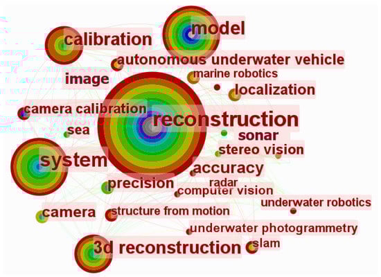
Figure 1.
Hot words in the field of underwater 3D reconstruction.
In addition, we also used the search result analysis function in Web of Science to analyze the research field statistics of papers published on the theme of underwater 3D reconstruction and the data cited by related articles. Figure 2 shows a line graph of the frequency of citations of related papers on the theme of underwater 3D reconstruction. The abscissa of the picture indicates the year and the ordinate indicates the number of citations of related papers. The graph shows that the number of citations of papers related to underwater 3D reconstruction rises rapidly as the years go on. Clearly, the area of underwater 3D reconstruction has received more and more attention, so this review is of great significance in combination with the current hotspots.
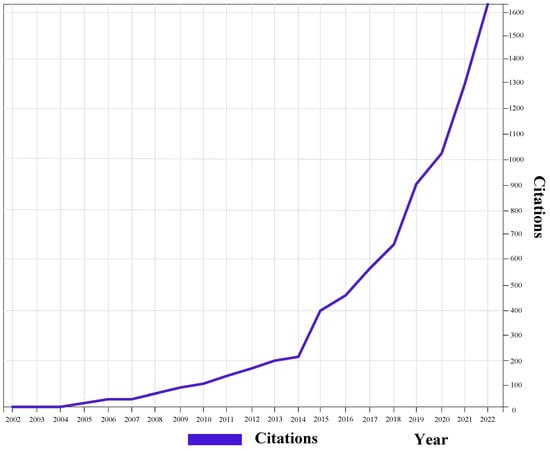
Figure 2.
Citations for Web of Science articles in recent years.
Figure 3 shows a histogram of statistics on the research field of papers published on the theme of underwater 3D reconstruction. The abscissa is the field of the retrieved paper and the ordinate is the number of papers in the field. Considering the research fields that retrieved relevant papers, underwater 3D reconstruction is a hot topic in engineering and computer science. Therefore, when we explore the direction of underwater 3D reconstruction, we should pay special attention to engineering issues and computer-related issues. From the above analysis, it is evident that the research on underwater 3D reconstruction is a hot topic at present, and it has attracted more and more attention as time progresses, mainly developing in the fields of computer science and engineering. Given the quick rise of deep learning methods in various fields [15,16,17,18,19,20,21,22,23], the development of underwater 3D reconstruction has also ushered in a period of rapid growth, which has greatly improved the reconstruction effect.
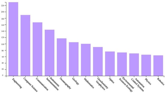
Figure 3.
Research fields of papers found using Web of Science.
Figure 4 shows the top 16 keywords with high frequency from 2005 to 2022 made using the Citespace software. Strength stands for the strength of the keyword, and the greater the value, the more the keyword is cited. The line on the right is the timeline from 2005 to 2022. The ‘begin’ column indicates the time when the keyword first appeared. ‘Begin’ to ‘End’ indicates that the keyword is highly active during this year. The red line indicates the years with high activity. It can be seen from the figure that words such as ‘sonar’, ‘underwater photogrammetry’, ‘underwater imaging’ and ‘underwater robotics’ are currently hot research topics within underwater three-dimensional reconstruction. The keywords with high strength, such as ‘structure from motion’ and ‘camera calibration’, clearly show the hot research topics in this field, and are also the focus of this article.
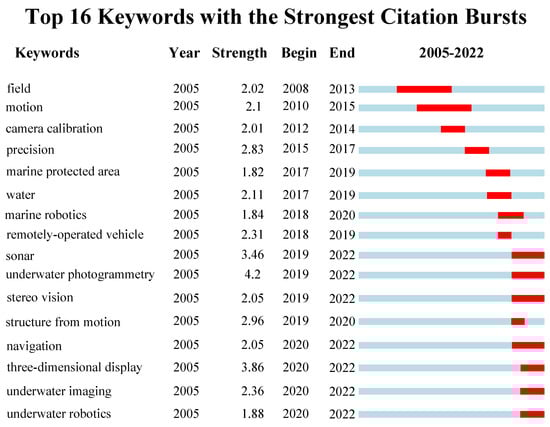
Figure 4.
Timing diagram of the appearance of high-frequency keywords.
Considering the ongoing advancements in science and technology, the desire to explore the sea has become stronger and stronger, and some scholars and teams have made significant contributions to underwater reconstruction. The contributions of numerous academics and groups have aided in the improvement of the reconstruction process in the special underwater environment and laid the foundation for a series of subsequent reconstruction problems. We retrieved more than 1000 articles on underwater 3D reconstruction from Web of Science and obtained the author contribution map shown in Figure 5. The larger the font, the greater the attention the author received.
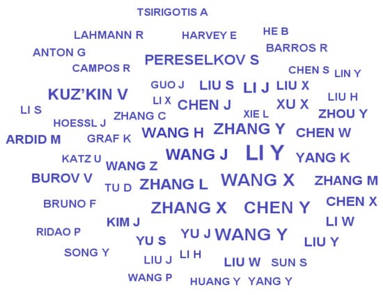
Figure 5.
Outstanding scholars in the area of underwater 3D reconstruction.
There are some representative research teams. Chris Beall et al. proposed a large-scale sparse reconstruction technology for underwater structures [24]. Bruno F et al. proposed the projection of structured lighting patterns based on a stereo vision system [25]. Bianco et al. compared two underwater 3D imaging technologies based on active and passive methods, as well as full-field acquisition [26]. Jordt A et al. used the geometric model of image formation to consider refraction. Then, starting from camera calibration, a complete and automatic 3D reconstruction system was proposed, which acquires image sequences and generates 3D models [27]. Kang L et al. studied a common underwater imaging device with two cameras, and then used a simplified refraction camera model to deal with the refraction problem [28]. Chadebecq F et al. proposed a novel RSfM framework [29] for a camera looking through a thin refractive interface to refine an initial estimate of the relative camera pose estimated. Song H et al. presented a comprehensive underwater visual reconstruction enhancement–registration–homogenization (ERH) paradigm [30]. Su Z et al. proposed a flexible and accurate stereo-DIC [31] based on the flat refractive geometry to measure the 3D shape and deformation of fluid-immersed objects. Table 1 lists their main contributions.

Table 1.
Some outstanding teams and their contributions.
This paper mainly used the Citespace software and Web of Science search and analysis functions to analyze the current development status and hotspot directions of underwater 3D reconstruction so that researchers can quickly understand the hotspots and key points in this field. In the next section, we analyze the uniqueness of the underwater environment in contrast to the conventional environment; that is, we analyzed the challenges that need to be addressed when performing optical image 3D reconstruction in the underwater environment.
3. Challenges Posed by the Underwater Environment
The development of 3D reconstruction based on optical image has been relatively mature. Compared with other methods, it has the benefits of being affordable and effective. However, in the underwater environment, it has different characteristics from conventional systems, mainly regarding the following aspects:
- (1)
- The underwater environment is complex, and the underwater scenes that can be reached are limited, so it is difficult to deploy the system and operate the equipment [32].
- (2)
- Data collection is difficult, requiring divers or specific equipment, and the requirements for the collection personnel are high [33].
- (3)
- The optical properties of the water body and insufficient light lead to dark and blurred images [34]. Light absorption can cause the borders of an image to blur, similar to a vignette effect.
- (4)
- When capturing underwater images in the air, there is a refraction effect between the sensor and the underwater object and between the air and the glass cover and the water due to the difference in density, which alters the camera’s intrinsic parameters, resulting in decreased algorithm performance while processing images [35]. Therefore, a specific calibration is required [36].
- (5)
- When photons propagate in an aqueous medium, they are affected by particles in the water, which can scatter or completely absorb the photons, resulting in the attenuation of the signal that finally reaches the image sensor [37]. The red, green and blue discrete waves are attenuated at different rates, and their effects are immediately apparent in the original underwater image, in which the red channel attenuates the most and the blue channel attenuates the least, resulting in the blue-green image effect [38].
- (6)
- Images taken in shallow-water areas (less than 10 m) may be severely affected by sunlight scintillation, which causes intense light variations as a result of sunlight refraction at the shifting air–water interface. This flickering can quickly change the appearance of the scene, which makes feature extraction and matching for basic image processing functions more difficult [39].
These engineering problems will affect the performance of underwater reconstruction systems. The algorithms of conventional systems used by researchers cannot often meet the needs of underwater practical applications with ease. Therefore, algorithm improvements are needed for 3D image reconstruction in underwater environments.
The 3D reconstruction of underwater images based on optics is greatly affected by the engineering problems proposed above. Research has shown that they can be mainly classified into two scientific problems, namely, the deterioration of underwater images and the calibration of underwater cameras. Meanwhile, underwater 3D reconstruction based on acoustic images is less affected by underwater environmental problems. Therefore, this section mainly introduces the processing of underwater image degradation and the improvement of underwater camera calibration for optical methods. They are the special features of conventional systems in underwater environments and are also the key and focus of underwater 3D reconstruction.
3.1. Underwater Image Degradation
The quality of the collected images is poor because of the unique underwater environment, which degrades the 3D reconstruction effect. In this section, we first discuss the caustic effect caused by light reflection or refraction in shallow water (water depth less than 10 m) and the solutions proposed by researchers. Second, we discuss image degradation caused by light absorption or scattering underwater and two common underwater image-processing approaches, namely underwater image restoration and visual image enhancement.
3.1.1. Reflection or Refraction Effects
Every depth in the underwater environment affects RGB images, but especially the caustics in shallow water (water depth less than 10 m), that is, the complex physical phenomenon of light reflected or refracted by a curved surface, which appears to be the primary factor lowering the image quality of all passive optical sensors [39]. In abyssal-sea photogrammetry methods, noon is usually the optimum period for data collection because of the bright illumination; with regard to shallow waters, the subject needs strong artificial lighting, or the image to be captured in shady conditions or on the horizon to avoid reflections on the seabed [39]. If it cannot be avoided in the procurement stage, the image-matching algorithm will be affected by caustics and lighting effects, with the final result being that the generated texture is different from the orthophoto. Furthermore, caustic effects destroy most image-matching algorithms, resulting in inaccurate matching [39]. Figure 6 shows pictures of different forms of caustic effects in underwater images.
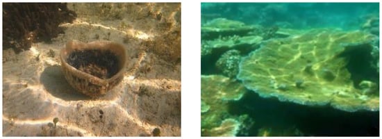
Figure 6.
Caustic effects of different shapes in underwater images.
Only a few literature contributions currently mention methods for optimizing images by removing caustics from images and videos. For underwater sceneries that are constantly changing, Trabes and Jordan proposed a method that requires altering a filter for sunlight deflection [40]. Gracias et al. [41] presented a new strategy, where a mathematical solving scheme involved computing the median time between images within a sequence. Later on, these authors expanded upon their work in [42] and proposed an online method for removing sun glint that interprets caustics as a dynamic texture. However, as they note in their research, this technique is only effective if the seabed or seafloor surface is level.
In [43], Schechner and Karpel proposed a method for analyzing several consecutive frames based on a nonlinear algorithm to keep the composition of the image the same while removing fluctuations. However, this method does not consider camera motion, which will lead to inaccurate registration.
In order to avoid inaccurate registration, Swirski and Schechner [44] proposed a method to remove caustics using stereo equipment. The stereo cameras provide the depth maps, and then the depth maps can be registered together using the iterative nearest point. This again makes a strong assumption about the rigidity of the scene, which rarely happens underwater.
Despite the innovative and complex techniques described above, removing caustic effects using a procedural approach requires strong assumptions on the various parameters involved, such as the scene stiffness and camera motion.
Therefore, Forbes et al. [45] proposed a method without making such assumptions, a new solution based on two convolutional neural networks (CNNs) [46,47,48]: SalienceNet and DeepCaustics. The saliency graph is the caustic classification produced by the first network when it is trained, and the content represents the likelihood of a pixel being caustic. Caustic-free images are produced when the second network is trained. The true fundamentals of caustic point generation are extremely difficult. They use synthetic data for training and then enable the transfer of learning to real data. This is the first time the challenging corrosion-removal problem has been reconstructed and approached as a classification and learning problem among the few solutions that have been suggested. Two compact, simple-to-train CNNs are the foundation of the unique solution that Agrafiotis et al. [39] proposed and tested a novel solution based on two small, easily trainable CNNs [49]. They showed how to train a network using a small set of synthetic data and then transfer the learning to real data with robustness to within-class variation. The solution results in caustic-free images that can be further used for other possible tasks. They showed how to train a network using a small set of synthetic data and then transfer the learning to real data with robustness to within-class variation. The solution results in caustic-free images that can be further used for other possible tasks.
3.1.2. Absorption or Scattering Effects
Water absorbs and scatters light as it moves through it. Different wavelengths of light are absorbed differently by different types of water. The underwater-imaging process is shown in Figure 7. At a depth of around 5 m, red light diminishes and vanishes quickly. Green and blue light both gradually fade away underwater, with blue light disappearing at a depth of roughly 60 m. Light changes direction during transmission and disperses unevenly because it is scattered by suspended matter and other media. The characteristics of the medium, the light and the polarization all have an impact on the scattering process [38]. Therefore, underwater video images are typically blue-green in color with obvious fog effects. Figure 8 shows some low-quality underwater images. The image on the left has obvious chromatic aberration, and the overall appearance is green. The image on the right demonstrates fogging, which is common in underwater images.
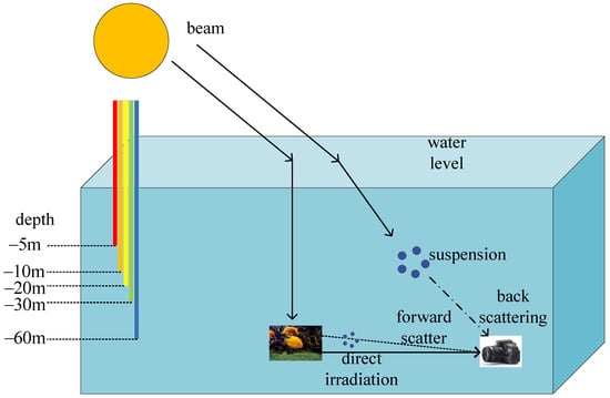
Figure 7.
Underwater imaging model.
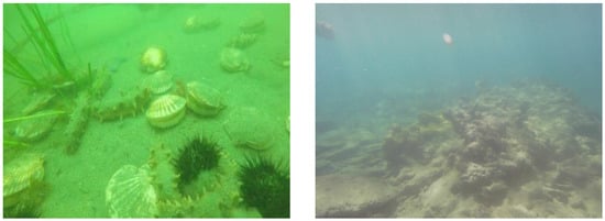
Figure 8.
Typical underwater images.
Low-quality images can affect subsequent 3D-reconstruction vision-processing missions. In actual utilization, projects are greatly hampered by the poor quality of underwater pictures, such as underwater archaeology, biological research and collection [50]. The underwater environment violates the brightness-constancy constraint in terrestrial techniques, so transferring reconstruction methods on land to the underwater domain remains challenging. The most advanced underwater 3D reconstruction approaches use the physical model of light propagation underwater to consider the equidistant effects of scattering and attenuation. However, these methods require careful calibration of the attenuation coefficients required for physical models or rely on rough estimates of these coefficients from previous laboratory experiments.
The current main method for 3D reconstruction of underwater images is to enhance the primordial underwater image before 3D reconstruction to restore the underwater image and possibly raise the level of the 3D point cloud that is produced [51]. Therefore, how to obtain as correct or real underwater color images as possible has become a very challenging problem, and at the same time it has become a promising research field. Underwater color images have affected image-based 3D-reconstruction and scene-mapping techniques [52].
To solve these problems, according to the description of underwater image processing in the literature, two different underwater image-processing methods are implemented. The first one is underwater image restoration. Its purpose is to reconstruct or restore degraded images caused by unfavourable factors, such as camera and object relative motion, underwater scattering, turbulence, distortion, spectral absorption and attenuation in complex underwater environments [53]. This rigorous approach tries to restore the true colors and corrects the image using an appropriate model. The second approach uses qualitative criteria-based underwater image-enhancement techniques [54,55]. It processes deteriorated underwater photographs using computer technology, turning the initial, low-quality images into high-quality images [56]. The enhancement technique effectively solves the issues with the primitive underwater video image, such as color bias, low contrast, fogging, etc. [57]. The visual perception improves with the enhancement of video images, which in turn facilitates the following visual tasks. The image-production process is not taken into account by image-enhancing techniques and does not require a priori knowledge of environmental factors [52]. New and better methods for underwater image processing have been made possible by recent developments in machine learning and deep learning in both approaches [22,58,59,60,61,62,63]. With the development of underwater image color restoration and enhancement technology, experts in the 3D reconstruction of underwater images are faced with the challenge of how to apply it to the 3D reconstruction of underwater images.
3.2. Underwater Camera Calibration
In underwater photogrammetry, the first aspect to consider is camera calibration, and while this is a trivial task in air conditions, it is not easy to implement underwater. Underwater camera calibration experiences more uncertainties than in-air calibration due to light attenuation through the housing ports and water medium, as well as tiny potential changes in the refracted light’s route due to the modelling hypothesis or nonuniformity of the medium error. Therefore, compared to identical calibrations in the air, underwater calibrations typically have a lower accuracy and precision. Due to these influences, experience has demonstrated that underwater calibration is more inclined to result in scale inaccuracies in the measurements [64].
Malte Pedersen et al. [65] compared three methods for the 3D reconstruction of underwater objects: a method relying only on aerial camera calibration, an underwater camera calibration method and a method based on Snell’s law with ray tracing. The aerial camera calibration display is the least accurate since it does not consider refraction. Therefore, the underwater camera needs to be calibrated.
As mentioned in the particularity of the underwater environment, the refraction of the air–glass–water interface will cause a large distortion of the image, which should be considered when calibrating the camera [66]. The differential in densities between the two mediums is what causes this refraction. The incoming beam of light is modified as it travels through the two mediums, as seen in Figure 9, altering the optical path.
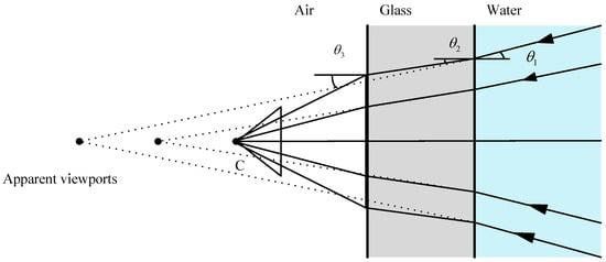
Figure 9.
Refraction caused by the air–glass (acrylic)–water interface.
Depending on their angle of incidence, refracted rays (shown by dashed lines) that extend into the air intersect at several spots, each representing a different viewpoint. Due to the influence of refraction, there is no collinearity between the object point in the water, the projection center of the camera and the image point [67], making the imaged scene appear wider than the actual scene. The distortion of the flat interface is affected by the distance from the pixel in the center of the camera, and the distortion increases with the distance. Variations in the pressure, temperature and salinity can change the refractive index of water and even how the camera is processed, thereby altering the calibration parameters [68]. Therefore, there is a mismatch between the object-plane coordinates and the image-plane coordinates.
This issue is mainly solved using two different methods:
- (1)
- The development of new calibration methods with a refraction-correction capability. Gu et al. [69] proposed an innovative and effective approach for medium-driven underwater camera calibration that can precisely calibrate underwater camera parameters, such as the direction and location of the transparent glass. To better construct the geometric restrictions and calculate the initial values of the underwater camera parameters, the calibration data are obtained using the optical path variations created by medium refraction between different mediums. At the same time, based on quaternions, they propose an underwater camera parameter-optimization method with the aim of improving the calibration accuracy of underwater camera systems.
- (2)
- The existing algorithm has been improved to reduce the refraction error. For example, Du et al. [70] established an actual underwater camera calibration image dataset in order to improve the accuracy of underwater camera calibration. The outcomes of conventional calibration methods are optimized using the slime mold optimization algorithm by combining the best neighborhood perturbation and reverse learning techniques. The precision and effectiveness of the proposed algorithm are verified using the seagull algorithm (SOA) and particle swarm optimization (PSO) algorithm on the surface.
Other researchers have proposed different methods, such as modifying the collinear equation. However, others have proposed that corrective lenses or circular holes can eliminate refraction effects and use dome-ported pressure shells, thereby providing near-perfect central projection underwater [71]. The entrance pupil of the camera lens and the center of curvature of the corrective lens must line up for the corrective-lens method to work. This presupposes that the camera is a perfect central projection. In general, to ensure the accuracy of the final results, comprehensive calibration is essential. For cameras with misaligned domes or flat ports, traditional methods of distortion-model adjustment are not sufficient, and complete physical models must be used [72], taking the glass thickness into account as in [67,73].
Other authors have considered refraction using the refraction camera model. As in [28], a simplified refraction camera model was adopted.
This section mainly introduces two main scientific problems arising from the special engineering problems of the underwater environment, namely, underwater image degradation and underwater camera calibration, and also introduces the existing solutions to the two main problems. In the next section, we introduce optical methods for the 3D reconstruction of underwater images. It uses optical sensors to obtain image information of underwater objects or scenes for reconstruction.
4. Optical Methods
Optical sensing devices can be divided into active and passive according to their interaction with media. Active sensor refers to sensors that can enhance or measure the collected data according to environmental radiation and projection. Structured light is an illustration of an active system, where a pattern is projected onto an object for 3D reconstruction [74]. The passive approach is to perceive the environment without changing or altering the scene. Structure from motion, photometric stereo, stereo vision and underwater photogrammetry acquire information by sensing the reality of the environment, and are passive methods.
This section introduces and summarizes the sensing technology of 3D underwater image reconstruction based on optical and related methods in detail and describes in detail the application of structure from motion, structured light, photometric stereo, stereo vision and underwater photogrammetry in underwater 3D reconstruction.
4.1. Structure from Motion
Structure from motion (SfM) is an efficient approach for 3D reconstruction using multiple images. It started with the pioneering paper of Longuet Higgins [75]. SfM is a method of triangulation that involves using a monocular camera to capture photographs of a subject or scene. To determine the relative camera motion and, thus, its 3D route, picture features are extracted from these camera shots and matched [76] between successive frames. First, suppose there is a calibrated camera in which the main point, calibration, lens distortion and refraction elements are known to ensure the accuracy of the final results.
Given a images of b fixed 3D points, then a projection matrices and b 3D points from the a·b correspondences of can be estimated.
Hence, the projection of the scene points is unaffected if the entire scene is scaled by a factor of m while also scaling the projection matrix by a factor of ; the projection of the scene points remains the same. Therefore, the scale is only unavailable with SfM.
The group of solutions parametrized by is:
where is the pseudo-inverse of P (i.e., ) and n is its null vector, namely, the camera center, defined by .
The SfM is the most economical method and easy to install on the robot, just needing a camera or recorder that can capture still images or video and has enough storage to hold the entire image. Essentially, SfM includes the automated tasks of feature-point detection, description and matching. The most critical tasks in this process are feature detection, description and matching, and then the required 3D model can be obtained. There are many feature-detection techniques that are frequently employed, including speeded-up robust features (SURF) [77], scale-invariant feature transform (SIFT) [78] and Harris. These feature detectors have spatially invariant characteristics. Nevertheless, they do not offer high-quality results when the images undergo significant modification, such as in underwater images. In fact, suspended particles in the water, light absorption and light refraction make the images blurred and add noise. To compare Harris and SIFT features, Meline et al. [79] used a 1280 × 720 px camera in shallow-water areas to obtain matching points robust enough to reconstruct 3D underwater archaeological objects. In this paper, the authors reconstructed a bust, and they concluded that the Harris method could obtain more robust points from the picture compared to SIFT, but the SIFT points could not be ignored either. Compared to Harris, SIFT is weak against speckle noise. Additionally, Harris presents better interior counts in diverse scenes.
SfM systems are a method for computing the camera pose and structure from a set of images [80] and are mainly separated into two types, incremental SfM and global SfM. Incremental SfM [81,82] uses SIFT to match the first two input images. These correspondences are then employed to estimate the relative pose of the second relative to the first camera. Once the poses of the two cameras are obtained, a sparse set of 3D points is triangulated. Although the RANSAC framework is often employed to estimate the relative poses, the outliers need to be found and eliminated once the points have been triangulated. The dual-view scenario is then optimized by applying bundle adjustment [83]. After the refactoring is initialized, other views are added in turn, that is, matching the corresponding relationship between the last view in the refactoring and the new view.
As a result of the 3D points presented in the reconstructed last view, a pair of new views with 2D–3D correspondences will be immediately generated. Therefore, the camera pose of the new view is determined by the absolute pose. A sequential reconstruction of scene models can be robust and accurate. However, with repeated registration and triangulation processes, the accumulated error becomes larger and larger, which may lead to scene drifts [84]. Additionally, repeatedly solving nonlinear bundle adjustments can lead to run-time inefficiencies. To prevent this from happening, a global SfM emerged. In this method, all correspondences between input image pairs are computed, so the input images do not need to be sorted [85]. Pipelines typically solve problems in three steps. The first step solves for all pairs of relative rotations through the epipolar geometry and constructs a view whose vertices represent the camera and whose edges represent the epipolar geometric constraints. The second step involves rotation averaging [86] and translation averaging [87], which address the camera orientation and motion, respectively. The final step is bundle adjustment, which aims to minimize the reprojection errors and optimize the scene structure and camera pose. Compared with incremental SfM, the global method avoids cumulative errors and is more efficient. The disadvantage is that it is not robust to outliers.
SfM has been shown to have good imaging conditions on land and is an effective method for 3D reconstruction [88]. In the underwater surroundings, using the SfM approach for 3D reconstruction has the characteristics of fast speed, ease of use and strong versatility, but there are also many limitations and deficiencies. In underwater media, both feature detection and matching have problems such as diffusion, uneven lighting and sun glints, making it more difficult to detect the same feature from different angles. According to the distance between the camera and the 3D point, the components of absorption and scattering change, thus altering the color and clarity of specific features in the picture. If the ocean is photographed from the air, there will be more difficulties, such as camera refraction [89].
Therefore, underwater SfM must take special underwater imaging conditions into consideration. Sedlazeck et al. [90], for the underwater imaging environment, proposed to computationally segment underwater images so that erroneous 2D correspondences can be segmented and eliminated. To eliminate the green or blue tint, they performed color correction using a physics model of light transmission underwater. Then, features were selected using an image-gradient-based Harris corner detector, and the outliers after feature matching were filtered through the RANSAC [91] process. The algorithm is essentially a classical incremental SfM method adapted to special imaging conditions. However, incremental SfM may suffer from scene drift. Therefore, Pizarro et al. [92] used a local-to-global SfM approach with the help of onboard navigation sensors to generate 3D submaps. They adopted a modified Harris corner detector as a feature detector with descriptors as generalized color moments and used RANSAC and the six-point algorithm that has been presented to evaluate the fundamental matrix stably, after breaking it down into movement parameters. Finally, the pose was optimized by minimizing all the reprojection errors that are considered as inline matches.
With the development of underwater robots, some authors have used ROVs and AUVs to capture underwater 3D objects from multiple angles and used continuous video streams to reconstruct underwater 3D objects. Xu et al. [93] combined SfM with an object-tracking strategy to try to explore a new model for underwater 3D object reconstruction from continuous video streams. A brief flowchart of their SfM reconstruction of underwater 3D objects is shown in Figure 10. First, the particle filter was used for image filtering to enhance the image, so as to obtain a clearer image for target tracking. They used SIFT and RANSAC to recognize and track features of objects. Based on this, a method for 3D point-cloud reconstruction with the support of SfM-based and patch-based multi-view stereo (PMVS) was proposed. This scheme achieves a consistent improvement in performance over multi-view 3D object reconstruction from underwater video streams. Chen et al. [94] proposed a clustering-based adaptive threshold keyframe-extraction algorithm, which extracts keyframes from video streams as image sequences for SfM. The keyframes are extracted from moving image sequences as features. They utilized the global SfM to create the scene and proposed a quicker rotational averaging approach, the least trimming square rotational average (LTS-RA) method, based on the least trimming squares (LTS) and L1RA methods. This method can reduce the time by 19.97%, and the dense point cloud reduces the transmission costs by around 70% in contrast to video streaming.
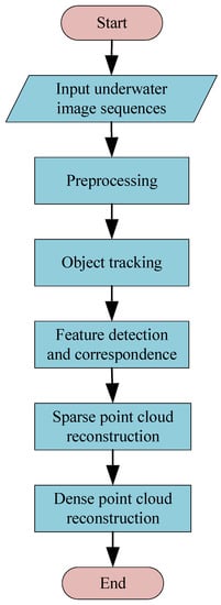
Figure 10.
Flow chart of underwater 3D object reconstruction based on SfM.
In addition, because of the diverse densities of water, glass and air, the light entering the camera housing causes refraction, and the light entering the camera is refracted twice. In 3D reconstruction, refraction causes geometric deformation. Therefore, refraction must be taken into account underwater. Sedlazeck and Koch [95] studied the calibration of housing parameters for underwater stereo camera setups. A refraction structure was developed based on a motion algorithm, a system for calculating camera paths and 3D points using a new pose-estimation method. In addition, they also introduced the Gauss–Helmert model [96] for nonlinear optimization, especially bundle adjustment. Both iterative optimization and nonlinear optimization are used within the framework of RANSAC. Using their proposed refraction SfM optimized the results of general SfM with a perspective camera model. A typical RSfM reconstruction system is shown in Figure 11, where j stands for the number of images. First, features in the two images are detected and matched, and then the relative pose of the second camera relative to the first camera is computed. Next, triangulation is performed using 2D–2D correspondences and camera poses. This finds the 2D–3D correspondence of the next image, so the absolute pose relative to the 3D point can be calculated. After adding fresh images and triangulating fresh points, a nonlinear optimization is used for the scene.
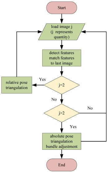
Figure 11.
Typical RSfM reconstruction system.
On the basis of Sedlazeck [90], Kang et al. [97] suggested two fresh ideasforof the refraction camera model, namely, the ellipse of refraction (EoR) and the profundity of refraction (RD) of scene points. Meanwhile, they proposed a new mixed majorization framework for performing dual-view underwater SfM. Compared to Sedlazeck [90], the algorithm they put forward permits more commonly used camera configurations and may efficiently minimize reprojection errors in picture interspace. On this basis, they derived two fresh expressions for the problem of undersea known rotating structures and motions in [28]. One provides a whole-situation optimum solution and the other is robust to abnormal values. The known rotation restraint is further broadened by introducing a robust known rotation SfM into a new mixed majorization framework. The means it can automatically perform underwater camera calibration and 3D reestablishment simultaneously without using any calibration objects or additional calibration devices, which significantly improves the precision of reconstructed 3D structures and the precision of the underwater application system parameters.
Jordt et al. [27] combined the refractive SfM routine and the refractive plane-sweep algorithm methods into an unabridged system for refraction reestablishment in larger scenes by improving nonlinear optimization. This study was the first to out forward, accomplish and assess an unabridged extensible 3D re-establishment system for deep-sea level port cameras. Parvathi et al. [98] only considered that refraction across medium boundaries could cause geometric changes that can result in incorrect correspondence matches between images. This method is only applicable to pictures acquired using a camera above the water’s surface, not underwater camera pictures, barring probable refraction at the glass–water interface. Therefore, they put forward a refraction re-establishment model to make up for refraction errors, assuming that the deflection of light rays takes place at the camera center. First, the correction parameters were modelled, and then the fundamental matrix was estimated using the coordinates of the correction model to build a multi-view geometric reconstruction.
Chadebecq et al. [99] derived a new four-view restraint formulation from refractive geometry and simultaneously proposed a new RSfM pipeline. The method depends on a refraction fundamental matrix derived from a generalized outer pole constraint, used together with a refraction–reprojection constraint, to optimize the primal estimation of the relative camera poses estimated using an adaptive pinhole model with lens distortion. On this basis, they extended the previous work in [29]. By employing the refraction camera model, a concise derivation and expression of the refraction basis matrix were given, and based on this, the former theoretical derivation of the two-view geometry with fixed refraction planes was further developed.
Qiao et al. [100] proposed a ray-tracing-based modelling approach for camera systems considering refraction. This method includes camera system modeling, camera housing calibration, camera system pose estimation and geometric reconstruction. They also proposed a camera housing calibration method on the basis of the back-projection error to accomplish accurate modelling. Based on this, a camera system pose-estimation method based on the modelled camera system was suggested for geometric reconstruction. Finally, the 3D reconstruction result was acquired using triangulation. The use of traditional SfM methods can lead to deformation of the reconstructed building, while their RSfM method can effectively reduce refractive index distortion and improve the final reconstruction accuracy.
Ichimaru et al. [101] proposed a technique to estimate all unknown parameters of the unified underwater SfM, such as the transformation of the camera and refraction interface and the shape of the underwater scene, using the extended beam-adjustment technique. Several types of constraints are used in optimization-based refactoring methods, depending on the capture settings, and an initialization procedure. Furthermore, since most techniques are performed under the assumption of planarity of the refraction interface, they proposed a technique to relax this assumption using soft constraints in order to apply this technique to natural water surfaces. Jeon and Lee [102] proposed the use of visual simultaneous localization and mapping (SLAM) to handle the localization of vehicle systems and the mapping of the surrounding environment. The orientation determined using SLAM improves the quality of 3D reconstruction and the computational efficiency of SfM, while increasing the number of point clouds and reducing the processing time.
In the underwater surroundings, the SfM method for 3D reconstruction is widely used because of its fast speed, ease of use and strong versatility. Table 2 lists different SfM solutions. In this paper, we mainly compared the feature points, matching methods and main contributions.
Table 2.
Summary of SfM 3D reconstruction motion solutions.
4.2. Photometric Stereo
Photometric stereo [103] is a commonly used optical 3D reconstruction approach that has the advantage of high-resolution and fine 3D reconstruction even in weakly textured regions. Photometric stereo scene-reconstruction technology needs to acquire a few photos taken in various lighting situations, and by shifting the location of the light source, 3D information may be retrieved, while maintaining a stable position for the camera and the objects. Currently, photometric stereo has been well-studied in air conditions and is capable of generating high-quality geometric data with specifics, but its performance is significantly degraded due to the particularities of underwater environments, including phenomena such as light scattering, refraction and energy attenuation [104].
The improvement of underwater photometric stereo under scattering effects has been widely discussed by researchers. In underwater environments, light is significantly attenuated due to scattering effects, resulting in an uneven illumination distribution in background areas. This leads to gradient errors and exacerbates the gradient integration in the photometric volume results in a buildup of height inaccuracies, which leads to the deformation of the reconstructed surface. Therefore, Narasimhan and Nayar [105] proposed a method for recovering the albedo, normal and depth maps from scattering media, deriving a physical model of surfaces surrounded by a scattering medium. Based on these models, they provide results on the conditions for detectability of objects in light fringes and the number of light sources required for the photometric stereo. It turns out that this method requires at least five images. Under special conditions, however, four different lighting conditions are sufficient.
Wu L et al. [106] better addressed the 3D reconstruction problem through low-rank matrix completion and restoration. They used scotoma, the shadow and blackness in the water, to accommodate the distribution of dispersion effects, and then removed dispersion from the graphics. The image was restored by eliminating minor noise, shadows, contaminants, and a few damaged points, due to the usage of backscatter compensating with the robust principal component analysis method (RPCA). Finally, to acquire the surface normal and finish the 3D reconstruction, they used the RPCA results and the least-squares results. Figure 12 uses four lamps to illuminate the underwater scene. The same scene is illuminated by different light sources to obtain an image for restoring 3D information. The new technology could be employed to enhance almost all photometric stereo methods, incorporating uncalibrated photometric stereo.
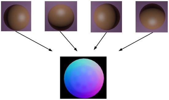
Figure 12.
Photometric stereo installation: four lights are employed to illuminate the underwater landscape. The same scene employed different light-source images to recover 3D information.
In [107], Tsiotsios et al. showed that only three lights are sufficient to calculate 3D data using a linear formulation of photometric stereo by effectively compensating for the backscattered component. They compensated for the backscattering component by fitting a backscattering model to each pixel. Without any prior knowledge of the characteristics of the medium or the scene, one can estimate the uneven backscatter directly from a single image using the backscatter restitution method for point-sources. Numerous experimental results have demonstrated that, even in the case of very significant scattering phenomena, there is almost no decrease in the final quality compared to the effects of clear water. However, just as in time-multiplexed structured-light technology, photometric stereo also has the problem of long acquisition time. These methods are inappropriate for objects that move and are only effective for close-range static objects in clear water. Inspired by the method proposed by Tsiotsios, Wu Z et al. [108] presented a height-correction technique for underwater photometric stereo reconstruction based on the backdrop area height distribution. To accommodate the height mistake, subtract it from the reconstructed height and provide a more accurate reconstructed surface, a two-dimensional quadratic function was applied. The experimental results show the effectiveness of the method in water with different turbidity.
Murez et al. [109] proposed three contributions to address the key modes of light propagation under the ordinary single-scattering assumption of diluted media. First, a large number of simulations showed that a single scattered light from a light source can be approximated by a point light source with a single direction. Then, the blur caused by light scattering from objects was modeled. Finally, it was demonstrated that imaging fluorescence emission, where available, removes the backscatter component and improves the signal-to-noise ratio. They conducted experiments in water tanks with different concentrations of scattering media. The results showed that the quality of 3D reconstruction generated by deconvolution is higher than that of previous techniques, and when combined with fluorescence, even for highly turbid media, similar results can be generated to those in clean water.
Jiao et al. [110] proposed a high-resolution three-dimensional surface reconstruction method for underwater targets based on a single RGBD image-fusion depth and multi-spectral photometric stereo vision. First, they used a depth sensor to acquire an RGB image of the object with depth information. Then, the backscattering was removed by fitting a binary quadratic function, and a simple linear iterative clustering superpixel was applied to segment the RGB image. Based on these superpixels, they used multispectral photometric stereo to calculate the objects’ surface normal.
The above research focused on the scattering effect in underwater photometric volumes. However, the effects of attenuation and refraction were rarely considered [111]. In underwater environments, cameras are usually designed in flat watertight housings. The light reflected from underwater objects is refracted as it passes through the flat housing glass in front of the camera, which can lead to inaccurate reconstructions. Refraction does not affect the surface normal estimations, but it may distort the captured image and cause height integration errors in the normal field when estimating the actual 3D position of the target object. At the same time, light attenuation limits the detection range of photometric stereo systems and reduces the accuracy. Researchers have proposed many methods to solve this problem in the air, for example, close-range photometric stereo, which simulates the light direction and attenuation per pixel [112,113]. However, these methods are not suitable for underwater environments.
Fan et al. [114] proposed that, when the light source of the imaging device is uniformly placed on a circle with the same tilt angle, the main components of low frequency and high deformation in the near photometric stereo can be approximately described by a quadratic function. At the same time, they proposed a practical method to fit and eliminate the height deviation so as to obtain a better surface-restoration method than the existing methods. It is also a valuable solution for underwater close-range photometric stereo. However, scale bias may occur due to the unstable light sensitivity of the camera sensor, underwater light attenuation and low-frequency noise cancellation [115].
In order to solve problems such as low-frequency distortion, scale deviation and refraction effects, Fan et al. combined underwater photometric stereo measurement with underwater laser triangulation in [116] to improve the performance of underwater photometric stereo measurement. Based on the underwater imaging model, an underwater photometric stereo model was established, which uses the underwater camera refraction model to remove the non-linear refraction distortion. At the same time, they also proposed a photometric stereo compensation method for close-range ring light sources.
However, the lack of constraints between multiple disconnected patches, the frequent presence of low-frequency distortions and some practical situations often lead to bias during photometric stereo reconstruction using direct integration. Therefore, Li et al. [117] proposed a fusion method to correct photometric stereo bias using the depth information generated by an encoded structured light system. This method preserves high-precision normal information, not only recovering high-frequency details, but also avoiding or at least reducing low-frequency deviations. A summary of underwater 3D reconstruction methods based on photometric stereo is shown in Table 3, which mainly compares the main considerations and their contributions.
Table 3.
Summary of photometric stereo 3D reconstruction solutions.
4.3. Structured Light
A structured light system consists of a color (or white light) projector and a camera. Between these two components and projected objects, the triangulation concept is applied. According to Figure 13, if both the plane and the camera ray are identifiable, the projector projects a recognized pattern onto the scene, often a collection of light planes. It is possible to compute the intersection between them using the following formula.
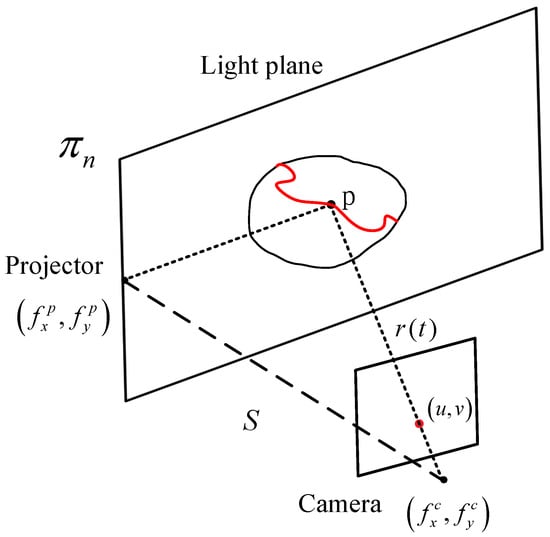
Figure 13.
Triangulation geometry principle of the structured light system.
Mathematically, a straight line can be expressed in parametric form as:
where is the focal length of the camera on the x and y axes, is the center pixel of the image and is one of the pixels detected in the image. Assuming a calibrated camera and origin camera frame, the light plane can be expressed as shown in Equation (5).
Binary modes are the most commonly employed as they are the simplest to use and implement with projectors. Only two states of the scene’s light streaks, typically white light, are utilized in the binary mode. The pattern starts out with just one sort of partition (black to white). Projections of the prior pattern’s subdivisions continue until the software is unable to separate two consecutive stripes, as seen in Figure 14. The time-multiplexing technique handles the related issue of continuous light planes. This method yields a fixed number of light planes that are typically related to the projector’s resolution. The time-multiplexing technique uses codewords generated by repeated pattern projections onto an object’s surface. As a result, until all patterns are projected, the codewords connected to specific spots in the image are not entirely created. According to a pattern of coarse to fine, the initial projection mode typically correlates to the most important portion. The number of projections directly affects the accuracy because each pattern introduces a sharper resolution to the image. Moreover, the codeword base is smaller, providing a higher noise immunity [118].
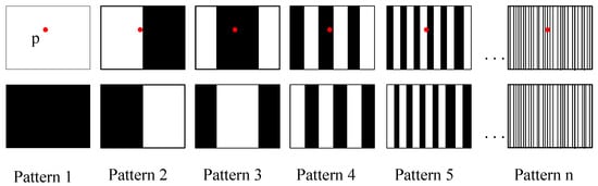
Figure 14.
Binary structured light pattern. The codeword for point p is created with successive projections of the patterns.
On the other hand, the phase-shift mode uses a sinusoidal projection to cover larger grayscale values in the same working mode. By decomposing the phase values, different light planes of a state can be obtained in the equivalent binary mode. A phase-shift graph is also a time-multiplexed graph. Frequency-multiplexing methods provide dense reconstructions of moving scenes, but are highly sensitive to camera nonlinearities, reducing the accuracy and sensitivity to target surface details. These methods utilize multiple projection modes to determine a distance. De Bruijn sequences can be reconstructed once using a pseudorandom sequence of symbols in a circular string. These patterns are known as m-arrays when this theory is applied to matrices rather than vectors (e.g., strings). They can be constructed by following pseudorandom sequences [119]. Often, these patterns utilize color to better distinguish the symbols of the alphabet. However, not all surface treatments and colors accurately reflect the incident color spectrum back to the camera [120].
In the air, shape, spatial-distribution and color-coding modes have been widely used. However, little has been reported on these encoding strategies in underwater scenes. Zhang et al. [121] proposed a grayscale fourth-order sinusoidal fringe. This mode employs four separate modes as part of a time-multiplexing technique. They compared structured light (SL) with stereo vision (SV), and SL showed better results on untextured items. Törnblom, in [122], projected 20 different gray-encoded patterns onto a pool and came up with results that were similar. The system achieved an accuracy of 2% in the z-direction. Massot-Campos et al. [123] also compared SL and SV in a common underwater environment of known size and objects. The results showed that SV is most suitable for long-distance and high-altitude measurements, depending on whether there is enough texture, and SL reconstruction can be better applied to short-distance and low-altitude methods, because accurate object or structure size is required.
Some authors combined the two methods of SL and SV to perform underwater 3D reconstruction. Bruno et al. [25] projected gray-encoded patterns with a terminal codeshift of four pixel broad bands. They used projectors to light the scene while gaining depth from the stereo deck. Therefore, there is no need to conduct lens calibration of the projection screen, and it is possible to utilize any projector that is offered for sale without sacrificing measurement reliability. They demonstrated that the final 3D reconstruction works well even with high haze values, despite substantial scattering and absorption effects. Similarly, using this method of SL and SV technology fusion, Tang et al. [124] reconstructed a cubic artificial reef (CTAR) in the underwater setting, proving that the 3D reconstruction quality in the underwater environment can be used to estimate the size of the CTAR set.
In addition, Sarafraz et al. extended the structured-light technique for the particular instance of a two-phase environment in which the camera is submerged and the projector is above the water [125]. The authors employed dynamic pseudorandom patterns combined with an algorithm to produce an array while maintaining the uniqueness of subwindows. They used three colors (red, green and blue) to construct the pattern, as shown in Figure 15. A projector placed above the water created a distinctive color pattern, and an underwater camera captured the image. Only one shot was required with this distinct color mode in order to rebuild both the seabed and the water’s surface. Therefore, it can be used in both dynamic scenes and static scenes.
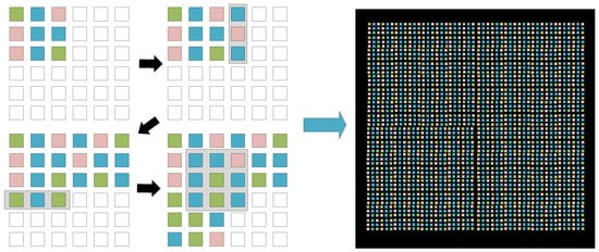
Figure 15.
Generating patterns for 3 × 3 subwindows using three colors (R, G, B). (left) Stepwise pattern generation for a 6 × 6 array; (right) example of a generated 50 × 50 pattern.
At present, underwater structured-light technology has received more and more concentration, primarily to address the 3D reconstruction of items and structures with poor textures and to circumvent the difficulty in employing conventional optical-imaging systems in hazy waters. The majority of structured-light techniques presumptively assume that light is neither dispersed nor absorbed and that the scene and light source are both submerged in pure air. However, in recent years, structured lighting has become more and more widely used in underwater imaging, and the scattering effect cannot be ignored.
Fox [126] originally proposed structured light using a single scanned light strip to lessen backscatter and provide 3D underwater object reconstruction. In this case, the basics of stereo-system calibration were applied to treat the projector as a reverse camera. Narasimhan and Nayar [105] developed a physical model of the appearance of a surface submerged in a scattering medium. In order to assess the media’s characteristics, the models describe how structured light interacts with scenes and media. This outcome can then be utilized to eliminate scattering effects and determine how the scene will appear. Using a model of image formation from strips of light, they created a straightforward algorithm to find items accurately. By reducing the illuminated area to the plane of the light, the shape of distant objects can be picked up for triangulation.
Another crucial concern for raising the performance of 3D reconstruction analysis based on the structured-light paradigm is the characterization of the projection patterns. An experimental investigation that assessed the effectiveness of several projected patterns and image-enhancement methods for detection under varied turbidity conditions revealed that, with increasing turbidity, the contrast loss is greater for stripes than for dots [127]. Therefore, Wang et al. [128] proposed a non-single-view point (SVP) ray-tracing model for calibrating projector camera systems for 3D reconstruction premised on the structured-light paradigm, using dot patterns as a basis. The rough depth map was reconstructed from the sparse point mode projection, and the gamut of surface points was used to texture the denser-mode image to improve point detection so as to estimate the finer surface reconstruction. Based on the medium, optical properties and projector camera geometry, they estimated the backscattering size and adjusted for signal attenuation to remove the picture for a specific projector pattern.
Massone et al. [129] proposed an approach that relies on the projection of light patterns, using a simple cone-shaped diving lamp as the projector. Images were recovered using closed 2D curves extracted by a light-profile-detection method they developed. They also created a new calibration method to determine the cone geometry relative to the camera. Thus, finding a match between the projection and recovery modes can be achieved by obtaining a fixed projector–camera pair. Finally, the 3D data were recovered by contextualizing the derived closed 2D curves and the camera conic relations.
Table 4 lists the underwater SL 3D reconstruction methods, mainly comparing colors, projector patterns and their main contributions.
Table 4.
Summary of SL 3D reconstruction solutions.
4.4. Stereo Vision
Stereo imaging works in the same manner as SfM, using feature matching between the stereo camera’s left and right frames to calculate 3D correspondences. After the stereo system has been calibrated, the relative position of one camera relative to the second camera was determined, thus resolving the problem of scale blur. The earliest stereo-matching technology was developed in the area of photogrammetry. Stereo matching has been extensively investigated in computer vision [130] and remains one of the most active study fields.
Suppose that there are two cameras and , and each camera image has two similar features and , as shown in Figure 16. To calculate the 3D coordinates of the feature F projected on as and projected on as , the line intersecting the focus and and the line intersecting the focus and are traced. If the calibration of both cameras is perfect, then . However, the least-squares method is typically used to address the camera-calibration problem, so the result is not always accurate. Therefore, an approximate solution is taken as the closest point between and [131].
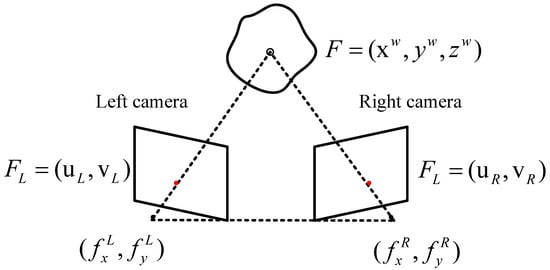
Figure 16.
Triangulation geometry principle of the stereo system.
After determining the relative position of the camera and the position of the same feature in the two images, the 3D coordinates of the feature in the world can be calculated through triangulation. In Figure 16, the image coordinate , and the 3D point corresponding to is the point , which can also be written as , where F is the fundamental matrix [131].
Once the cameras are calibrated (the baseline, relative camera pose and undistorted image are known), 3D imaging can be produced by computing the divergence of each pixel. These 3D data are gathered, and other 3D registration techniques can be used to register between successive frames and the iterative closest point (ICP) [132]. SIFT, SURF and the sum of absolute differences (SAD) [133] are the most-commonly employed methods, and SIFT or ICP can also be used for direct 3D matching.
Computer vision provides promising techniques for constructing 3D models of environments from 2D images, but underwater environments suffer from increased radial distortion due to the refraction of light rays through multiple media. Therefore, the underwater camera-calibration problem is very important in stereo vision systems. Rahman et al. [134] studied the differences between terrestrial and underwater camera calibrations, quantitatively determining the necessity of in situ calibration for underwater environments. They used two calibration algorithms, the Rahman–Krouglicof [135] and Heikkila [136] algorithms, to calibrate the underwater SV system. The stereo capability of the two calibration algorithms was evaluated from the perspective of the reconstruction error, and the experimental data confirmed that the Rahman–Krouglicof algorithm could solve the characteristics of underwater 3D reconstruction well. Oleari et al. [137] proposed a camera-calibration approach for SV systems without the need for intricate underwater processes. It is a two-stage calibration method in which, in the initial phase, an air standard calibration is carried out. In the following phase, utilizing prior data on the size of the submerged cylindrical pipe, the camera’s settings are tuned. Deng et al. [138] proposed an aerial calibration method for binocular cameras for underwater stereo matching. They investigated the camera’s imaging mechanism, deduced the connection between the camera in the air and underwater and carried out underwater stereo-matching experiments using the camera parameters calibrated in the air, and the results showed the effectiveness of the method.
SLAM is the most accurate positioning method, using the data provided by the navigation sensors installed on the underwater vehicle [139]. To provide improved reconstructions, rapid advances in stereo SLAM have also been applied underwater. These methods make use of stereo cameras to produce depth maps that can be utilized to recreate environments in great detail. Bonin-Font et al. [140] compared two different stereo-vision-based SLAM methods, graph-SLAM and EKF SLAM, for the real-time localization of moving AUVs in underwater ecosystems. Both methods utilize only 3D models. They conducted experiments in a controllable water scene and the sea, and the results showed that, under the same working and environmental conditions, the graph-SLAM method is superior to the EKF counterpart method. SLAM pose estimation based on the globalized framework, matching methods with small cumulative errors, was used to reconstruct a virtual 3D map of the surrounding area from a combination of contiguous stereo-vision point clouds [141] placed at the corresponding SLAM positions.
One of the main problems of underwater volumetric SLAM is the refractive interface between the air inside the container and the water outside. If refraction is not taken into account, it can severely distort both the individual camera images and the depth that is calculated as a result of stereo correspondence. These mistakes might compound and lead to more significant mistakes in the final design. Servos et al. [142] generated dense, geometrically precise underwater environment reconstructions by correcting for refraction-induced image distortions. They used the calibration images to compute the camera and housing refraction models offline and generate nonlinear epipolar curves for stereo matching. Using the SAD block-matching algorithm, a stereo disparity map was created by executing this 1D optimization along the epipolar curve for each pixel in the reference image. The junction of the left and right image rays was then located utilizing pixel ray tracing through the refraction interface to ascertain the depth of each corresponding pair of pixels. They used ICP to directly register the generated point clouds. Finally, the depth map was employed to carry out dense SLAM and produce a 3D model of the surroundings. The SLAM algorithm combines ray tracing with refraction correction to enhance the map accuracy.
The underwater environment is more challenging than that on land, and directly applying standard 3D reconstruction methods underwater will make the final effect unsatisfactory. Therefore, underwater 3D reconstruction requires accurate and complete camera trajectories as a foundation for detailed 3D reconstruction. High-precision sparse 3D reconstruction determines the effect of subsequent dense reconstruction algorithms. Beall et al. [24] used stereo image pairs, detected salient features, calculated 3D locations and predicted the camera pose’s trajectory. SURF features were extracted from the left and right image pairs using synchronized high-definition video acquired with a wide-baseline stereo setup. The trajectories were used together with 3D feature points as a preliminary estimation and optimized with feedback to smoothing and mapping. After that, the mesh was texture-mapped with the image after the 3D points were triangulated using Delaunay triangulation. This device is being used to recreate coral reefs in the Bahamas.
Nurtantio et al. [143] used a camera system with multiple views to collect subsea footage in linear transects. Following the manual extraction of image pairs from video clips, the SIFT method automatically extracted related points from stereo pairs. Based on the generated point cloud, a Delaunay triangulation algorithm was used to process the sum of 3D points to generate a surface reconstruction. The approach is robust, and the matching accuracy of underwater images reached more than 87%. However, they manually extracted image pairs from video clips and then preprocessed the images.
Wu et al. [144] improved the dense disparity map, and their stereo-matching algorithm included a disparity-value search, per-pixel cost calculation, difference cumulative integral calculation, window statistics calculation and sub-pixel interpolation. In the fast stereo-matching algorithm, biological vision consistency checks and uniqueness-verification strategies were adopted to detect occlusion and unreliable matching and eliminate false matching of the underwater vision system. At the same time, they constructed a disparity map, that is, the relative profundity data of the ocean SV, to complete the three-dimensional surface model. It was further adjusted with image quality enhancement combined with homomorphic filtering and wavelet decomposition.
Zheng et al. [145] proposed an underwater binocular SV system under non-uniform illumination based on Zhang’s camera-calibration method [146]. For stereo matching, according to the research on SIFT’s image-matching technology, they adopted a new matching method that combines characteristic matching and district matching as well as margin features and nook features. This method can decrease the matching time and enhance the matching accuracy. The three-dimensional coordinate projection transformation matrix solved using the least-squares method was used to accurately calculate the three-dimensional coordinates of each point in the underwater scene.
Huo et al. [147] ameliorated the semi-global stereo-matching method through severely constraining the matching process within the effective region of the object. First, denoising and color restoration were carried out on the image sequence that was obtained by the system vision, and the submerged object was separated into segments and retrieved in accordance with the saliency of the image using the superpixel segmentation method. The base disparity map within each superpixel region was then optimized using a least-squares fitting interpolation method to decrease the mismatch. Finally, on the basis of the post-optimized disparity map, the 3D data of the target were calculated using the principle of triangulation. The laboratory finding showed that, for underwater targets of a specific size, the system could obtain a high measuring precision and good 3D reconstruction result within an appropriate distance.
Wang et al. [148] developed an underwater stereo-vision system for underwater 3D reconstruction using state-of-the-art hardware. Using Zhang’s checkerboard calibration method, the inherent parameters of the camera were limited by corner features and the simplex matrix. Then, a three-primary-color calibration method was adopted to correct and recover the color information of the image. The laboratory finding proved that the system corrects the underwater distortion of stereo vision and can effectively carry out underwater three-dimensional reconstruction. Table 5 lists the underwater SV 3D reconstruction methods, mainly comparing the features, feature-matching methods and main contributions of the articles.
Table 5.
Summary of SV 3D reconstruction solutions.
4.5. Underwater Photogrammetry
From the use of cameras in underwater environments, the sub-discipline of underwater photogrammetry has emerged. Photogrammetry is identified as a competitive and agile underwater 3D measurement and modelling method, which may produce unforgettable and valuable results at various depths and in far-ranging application areas. In general, any actual 3D reconstruction method that uses photographs (such as imaging-based methods) to obtain measurement data is a photogrammetry method. Photogrammetry includes image measurement and interpretation methods often shared with other scientific fields to reach the shape and position of an object or target from a suite of photographs. Therefore, techniques such as structure from motion and stereo vision pertain to the field of photogrammetry and computer vision.
Photogrammetry is flexible in underwater environments. In shallow waters, divers use photogrammetry systems to map arched geological sites, monitor fauna populations and investigate shipwrecks. In deep water, ROVs with a variable quantity of cameras increase the depth scope of underwater inspections. The collection of photographs that depict the real condition of the position and objects is an important added value of photogrammetry compared to other measurement methods. In photogrammetry, a camera is typically placed in a large field of view to observe a remote calibration target whose precise location was pre-calculated using the measuring instrument. Based on the camera position and object distance, photogrammetry applications can be divided into various categories. For instance, aerial photogrammetry is usually measured at an altitude of 300 m [149].
The topic of image quality is crucial to photogrammetry. Camera calibration is one of the key themes covered by this topic. If perfect metric precision is necessary, the aforementioned pre-calibrated camera technique must be used, with ground control points to reconstruct [150]. Abdo et al. [151] argued that a photogrammetric system for complex biological items that may be used underwater must (1) be capable of working in confined areas; (2) provide easy access to data efficiently in situ; and (3) offer a survey procedure that is simple to implement, accurate and can be finished in a fair amount of time.
Menna et al. [152] proposed a method for the 3D measurement of floating and semi-submerged underwater targets (as shown in Figure 17) by performing photogrammetry twice below and above sea level, and that can be compared directly within the same coordinate system. During the measurements, they attached special devices to the objects, with two plates, one above and one below sea level. The photogrammetry was carried out twice in each medium, one for the underwater portion, the other for the surface of the water. Then, a digital 3D model was achieved through an intensive image-matching procedure. Moreover, in [153], the authors presented for the first time the evaluation of vision-based SLAM algorithms using high-precision ground-truthing of the underwater surroundings and a verified photogrammetry-based imaging system in the specific context of underwater metrology surveys. An accuracy evaluation was carried out using the completed underwater photogrammetric system ORUS 3D®. The system uses the certified 3D underwater reference test field in COMEX facilities, and its coordinate accuracy can reach the submillimeter level.
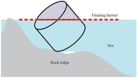
Figure 17.
Sectional view of an underwater semi-floating object.
Zhukovsky et al. [154] presented an example of the use of archaeological photogrammetric methods for site documentation during the underwater excavation of a Phanagorian shipwreck. The benefits and potential underwater limitations of the adopted automatic point-cloud-extraction method were discussed. At the same time, they offered a comprehensive introduction to the actual workflow of photogrammetry applied in the dig site: photo acquisition process and control point survey. Finally, a 3D model of the shipwreck was provided, and the development prospect of automatic point-cloud-extraction algorithms for archaeological records was summarized.
Nornes et al. [155] proposed an ROV-based underwater photogrammetric system, showing that a precise 3D model can be generated with a geographical reference only with a low-resolution canera (1.4 million pixels) and ROV navigation data, thus improving exploration efficiency. Many pictures were underexposed and some were overexposed as a result of the absence of automatic target-distance control. To make up for this, the automatic white-balance function in GIMP 2.8, an open-source image manipulation program, was used to color-correct the pictures. With the use of this command, an image’s color can be automatically changed by individually expanding its red, green and blue channels. After recording the time stamp and navigation data of the image, they used MATLAB to calculate the camera position. The findings highlighted the future improvements that could be made by eliminating the reliance on pilots, not only for the sake of data quality, but also in further reducing the resources required for investigations.
Guo et al. [156] compared the accuracy of 3D point clouds generated from images obtained by cameras with underwater shells and popular GoPro cameras. When they calibrated the cameras on-site, they found that the GoPro camera system had large variations whether in the air or underwater. Their 3D models were determined using Lumix cameras in the air, and these models were compared (best possible values) as point clouds of individual objects underwater that were further used to check the precision of point-cloud generation. An underwater photogrammetric scheme was provided to detect the growth of coral reefs and record the changes of ecosystems in detail, with an accuracy of mm.
Balletti et al. [157] used the trilateral method (direct measurement method) and GPS RTK survey to measure the terrain. According to the features, depth and distribution of marble objects on the seabed, two 3D polygon texture models were utilized to analyze and reconstruct different situations. In the article, they introduced all the steps of their design, acquisition and preparation, as well as the final data processing.
5. Acoustic Image Methods
At present, the 3D reconstruction technology based on underwater optical images is very mature. However, because of the complexity and diversity of the underwater environment and the rapid attenuation of light-wave energy in underwater propagation, underwater 3D reconstruction based on optical images often has difficulties in meeting the application needs of the actual conditions. The propagation of sound waves in water has the characteristics of low loss, strong diffraction ability, long propagation distance and little influence of the water quality conditions. It has better imaging effects in complex underwater environments and deep water without light sources. Therefore, underwater 3D reconstruction based on sonar images has a good research prospect. However, sonar also has the disadvantages of low resolution, difficult data extraction and inability to provide accurate color information. Therefore, the combination of study data, taking advantage of the complementarity of optical and sonar sensors, is a promising emerging field for underwater 3D reconstruction. Therefore, this section reviews the sonar-based underwater 3D reconstruction techniques based on acoustics and optical–acoustic fusion.
5.1. Sonar
Sonar stands for sound navigation and ranging. Sonar is a good choice for studying underwater environments because it does not take into account the environmental dependence of brightness and disregards the turbidity of the water. There are two main categories of sonar: active and passive. The sensors of passive sonar systems are not employed for 3D reconstruction, so they will not be studied in this paper.
Active sonar produces sound pulses and then monitors the reflection of the pulses. The frequency of the pulse can be either constant or chirp with variable frequency. If a chirp is present, the receiver will correlate the reflected frequency with the well-known signal. Generally speaking, long-range active sonar uses lower frequencies (hundreds of kilohertz), while short-range high-resolution sonar uses higher frequencies (several megahertz). Within the category of active sonar, multibeam sonar (MBS), single-beam sonar (SBS) and side-scan sonar (SSS) are the three most significant types. If the cross-track angle is very large, it is often referred to as imaging sonar (IS). Otherwise, they are defined as profile sonars because they are primarily utilized to assemble bathymetric data. In addition, these sonars can be mechanically operated for scanning and can be towed or mounted on a vessel or underwater craft. Sound travels faster in water than in air, although its speed is also dependent on the temperature and salinity of the water [158]. The long-range detection capability of sonar depth sounding makes it an important underwater depth-measurement technology that can collect depth data from watercraft on the surface and even at depths of thousands of meters. At close ranges, the resolution can reach several centimeters. However, at long ranges of several kilometers, the resolution is relatively low, typically on the order of tens of centimeters to meters.
Bathymetric data collection is most commonly used with MBS. The sensor can be associated with a color camera to obtain 3D information and color information. In this situation, however, it is narrowed down to the visible range. The MBS can also be installed on a tilting system for total 3D scanning. They are usually fitted on a tripod or ROV and need to be kept stationary during the scanning process. Pathak et al. [159] used Tritech Eclipse sonar, an MBS with delayed beam forming and electronic beam steering, to generate a final 3D map after 18 scans. On the basis of the region grown in distance image scanning, the plane was extracted from the original point cloud. Least-squares estimation of the planar parameters was then performed and the covariance of the planes parameters is calculated. Planes were fitted to the sonar data and the subsequent registration method maximized the entire geometric homogeneity in the search space to determine the correspondence between the planes. Then, the plane registration method, namely, minimum uncertainty maximum consistency (MUMC) [160], was used to determine the correspondence between the planes.
SBS is a two-dimensional mechanical scanning sonar that can be scanned in 3D by spinning its head, just like a one-dimensional ranging sensor mounted on the translation and tilt head. The data retrieval is not as quick as MBS, but it is cheap and small. Guo et al. [161] used single-beam sonar (SBS) to reconstruct the 3D underwater terrain of an experimental pool. They used Blender, an open-source 3D modelling and animation software, as their modelling platform. The sonar obtained 2D slices of the underwater context along a straight line and then combined these 2D slices to create a 3D point cloud. Then, a radius outlier removal filter, condition removal filter and voxel grid filter were used to smooth the 3D point cloud. In the end, an underwater model was constructed using a superposition method based on the processed 3D point cloud.
The profile analysis can also be completed with SSS, which is usually pulled or installed on the AUV for grid measurement. SSS is able to understand differences in seabed materials and texture types, making it an effective tool for detecting underwater objects. To accurately differentiate between underwater targets, the concept of 3D imaging based on SSS images has been proposed [162,163] and is becoming increasingly important in activities such as wreck visualization, pipeline tracking and mine search. While the SSS system does not provide direct 3D visualization, the images they generate can be converted into 3D representations using echo intensity information contained in the grayscale images through algorithms [164]. Whereas multibeam systems are expensive and require a robust sensor platform, SSS systems are relatively cheap and easy to deploy and provide a wider area coverage.
Wang et al. [165] used SSS images to reconstruct the 3D shape of underwater objects. They segmented the sonar image into three types of regions: echoes, shadows and background. They evaluated 2D intensity maps from the echoes and calculated 2D depth maps from the shade data. A 2D intensity map was obtained by thresholding the original image, denoising it and generating a pseudo-color image. Noise reduction uses order statistics filter to remove salt-and-pepper noise. With regard to slightly larger points, they used the bwareaopen function to delete all linked pixels smaller than the specified area size. Histogram equalization was applied to distinguish the shadows and background, and then the depth map was obtained from the shadow information.The geometric structure of SSS is shown in Figure 18. Through plain geometric deduction, the height of the object above the seabed can be reckoned by employing Equation (7):
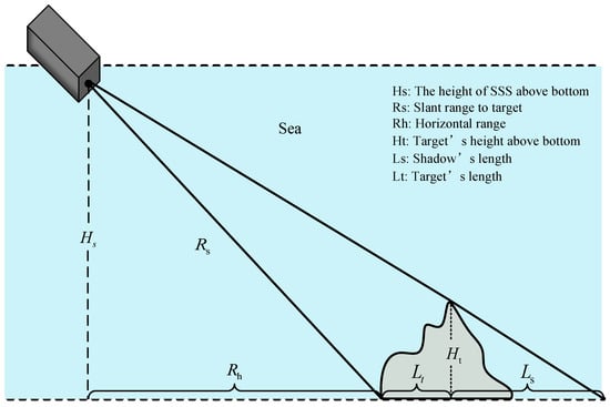
Figure 18.
Side-scan sonar geometry.
For areas followed by shadows, the height of these areas can be directly calculated with Equation (8):
Then, the model was transformed, and finally the 2D intensity map and 2D depth map was reconstructed to generate a 3D point-cloud image of the underwater target for 3D reconstruction.
The above three sonars are rarely used in underwater 3D reconstruction, and IS is currently the most-widely used. The difference between IS and MBS or SBS is that the beam angle becomes wider (they capture an acoustic image of the seafloor rather than a thin slice). Brahim et al. [166] reestablished the underwater environment utilizing two pictures of the same scene obtained from different angles with an acoustic camera. They used the DIDSON acoustic camera to provide a series of 2D images in which each pixel in the scene contained backscattered energy located at the same distance and azimuth. They proposed that by understanding the geometric shape of the rectangular grid observed on multiple images obtained from different viewpoints, the image distortion can be deduced and the geometric deviation of the acoustic camera can be compensated. This procedure depends on minimizing the divergence between the ideal model (the mesh projected using the ideal camera model) and its representation in the recorded image. Then the covariance matrix adaptive evolutionary strategy algorithm was applied to reconstruct the 3D scene from the missing estimation data of each matching point distilled from the pair of images.
Object shadows in acoustic images can also be made use of in restoring 3D data. Song et al. [167] used 2D multibeam imaging sonar for the 3D reconstruction of underwater structures. The acoustic pressure wave generated by the imaging sonar transmitter propagated and reflected on the surface of the underwater system, and these reflected echoes were collected by the 2D imaging sonar. Figure 19 is a collected sonar image where each pixel shows the reflection intensity of a spot at the same distance without showing elevation information. They found target shadow pairs in sequential sonar images by analyzing the reflected sonar intensity patterns. Then, they used Lambert’s reflection law and the shadow length to calculate the elevation information and elevation angle information. Based on this, they proposed a 3D reconstruction algorithm in [168], which converts the two-dimensional pixel coordinates of the sonar image into the corresponding three-dimensional space coordinates of the scene surface by recovering the missing surface elevation in the sonar image, so as to realize the three-dimensional visualization of the underwater scene, which can be used for marine biological exploration using ROVs. The algorithm classifies the pixels according to the intensity value of the seabed, divides the objects and shadows in the image and then calculates the surface elevation of object pixels according to the intensity value to obtain the elevation-correction agent. Finally, using the coordinate transformation from the image plane to the seabed, the 3D coordinates of the scene surface were reconstructed using the recovered surface elevation values. The experimental results showed that the proposed algorithm can reconstruct the surface of the reference target successfully, and the target size error was less than 10%, which has a certain applicability in marine biological exploration.
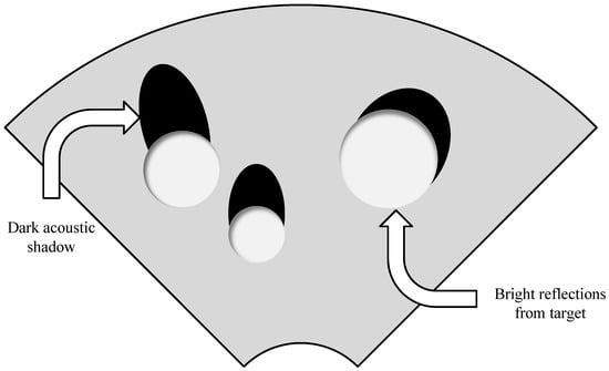
Figure 19.
Sonar image [167].
Mechanical scanning imaging sonar (MSIS) has been widely used to detect obstacles and sense underwater environments by emitting ultrasonic pulses to scan the environment and provide echo intensity profiles in the scanned range. However, few studies have used MSIS for underwater mapping or scene reconstruction. Kwon et al. [169] generated a 3D point cloud utilizing the MSIS beamforming model. They proposed a probabilistic model to determine a point cloud’s occupied likelihood for a specific beam. However, MSIS results are unreliable and chaotic. To overcome this restriction, a program that corrects the strength was applied that increased the volume of echoes with distance. Specific thresholds were then applied to specific ranges of the signal to eliminate artifacts, which are caused by the interaction between the sensor housing and the released acoustic pulse. Finally, an octree-based database schema was utilized to create maps efficiently. Justo et al. [170] obtained point clouds representing scanned surfaces using MSIS sonar. They used cutoff filters and adjustment filters to remove noise and outliers. Then, the point cloud was transformed onto the surface using classical Delaunay triangulation, allowing for 3D surface reconstruction. The method was intended to be applied to studies of submerged glacier melting.
The large spatial footprints of wide-aperture sensors makes it possible to image enormous volumes of water in real time. However, wider apertures lead to blurring through more complicated image models, decreasing the spatial resolution. To address this issue, Guerneve et al. [171] proposed two reconstruction methods. They first proposed a magnificent linear equation as the kernel for blind deconvolution with spatial variation. The next technique is an easy approximated reconstruction algorithm with the aid of a nonlinear approximation of the sculpting algorithm. Three-dimensional reconstructions can be performed immediately from the large-aperture system’s data records using simple approximation algorithms. As shown in Figure 20, the three primary steps of the sculpting algorithm’s online implementation are as follows: The sonar image’s circular extension from 2D to 3D is performed, whose intensity is based on the scale of the beam arrangement. As fresh observations are made, the 3D map of the scene is subsequently updated, eventually covering the entire scene. In order to build the final map, the final step manipulates the occlusion resolution while keeping only the front surface of the scene that was viewed. Their proposed method effectively eliminates the need to embed multiple acoustic sensors with different apertures.
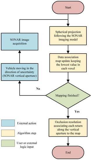
Figure 20.
Flow chart of online carving algorithm based on imaging sonar.
Some authors have proposed the method of isomorphic fusion, that is, multi-sonar fusion. The wide-aperture forward-looking multibeam imaging sonar provides a wide range of views and the flexibility to collect images from a variety of angles. However, imaging sonars are characterized by high signal-to-noise ratios and a limited number of observations, giving a 2D image in flat form of the observed 3D region and resulting in a lack of measurements of elevation angles that can affect the outcome of the 3D rebuilding. McConnell et al. [172] proposed a sequential approach to extract 3D information utilizing sensor fusion between two sonar systems to deal with the problem of elevation ambiguity associated with forward-looking multibeam imaging sonar observations. Using a pair of sonars with orthogonal uncertainty axes, they noticed the same point in the environment independently from two distinct perspectives. The range, intensity and local average of intensities were employed as feature descriptors. They took advantage of these concurrent observations to create a dense, fully defined point cloud at each period. The point cloud was then registered using ICP. Likewise, 3D reconstruction from forward-looking multibeam sonar images results in a loss of pitch angle.
Joe et al. [173] used an additional sonar to reconstruct missing information by exploiting the geometrical constraints and complementary properties between two installed sonar devices. Their proposed fusion method moves through three levels. The first step is to create a likelihood map utilizing the two sonar installations’ geometrical restrictions. The next step is to create workable elevation angles for the forward-looking multibeam sonar (FLMS). The third stage corrects the FLMS data by calculating the weights of the generated particles using a Monte Carlo stochastic approach. This technique can easily recreate the 3D information of the seafloor without the additional modification of the trajectory and can be combined with the SLAM framework.
The imaging sonar approach for creating 3D point clouds has flaws, such as the frontal surface’s unacceptable slope, sparse data, missing side and back information. To address these issues, Kim et al. [174] proposed a multiple-view scanning approach to replace the single-view scanning method. They applied the spotlight expansion impact to obtain the 3D data of the underwater target. Utilizing this situation, it is possible to reconstruct the elevation angle details of a given area in a sonar image and generate a 3D point cloud. The 3D point cloud information is processed afterward to choose the appropriate following scan processes, i.e., increasing the size of the beam reflection and its orthogonality to the prior path.
Standard mesh searching produces uncountable invalid triangle faces, and many holes are developed. Therefore, Li et al. [175] used an adaptive threshold to search for non-empty sonar information points, first in 2 × 2 grid blocks, and then searched for 3 × 3 grid blocks centered on the vacant locations to increase the sonar image holes. The program then searched the sonar array for 3 × 2 horizontal grid blocks and 2 × 3 vertical grid blocks to further improve the connectivity relationship by discovering semi-diagonal interconnections. Subsequently, using the discovered sonar data point connections, triangle connection and reconstruction were carried out.
In order to estimate the precise attitude of the acoustic camera and measure the three-dimensional location of underwater target key elements in a similar manner, Mai et al. [176] proposed a technique based on Extended Kalman Filter (EKF), for which an overview is shown in Figure 21. A conceptual diagram of the suggested approach based on multiple acoustic viewpoints is shown in Figure 22. Regarding the input data, the acoustic camera’s image sequence and camera motion input data were combined. The EKF algorithm was used to estimate the three-dimensional location of the skeletal characteristic elements of the underwater object and the pose of the six-degree-of-freedom acoustic camera as output information. By using a probabilistic EKF-based approach, even when there are ambiguities in the control inputs for camera motion, it is still possible to reconstruct 3D models of underwater objects. However, this research was founded on basic feature factors. For low-level features, the feature matching process often fails due to the indistinguishability between features, resulting in a reduced precision of the 3D recreation. For feature-point assemblage and excavation, it is dependent on prior awareness of the identified features, followed by the manual sampling of acoustic-image features.
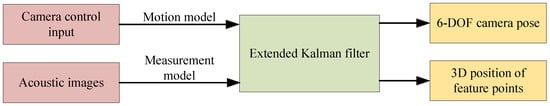
Figure 21.
Overview of the Extended Kalman Filter algorithm.
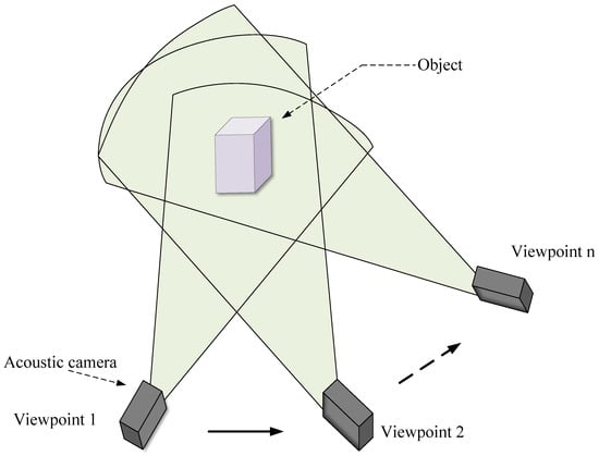
Figure 22.
Observation of underwater objects using an acoustic camera from multiple viewpoints.
Therefore, to solve this problem, in [177], they used use line segments rather than points as landmarks. An acoustic camera representing a sonar sensor was employed in order to extract and track underwater object lines, which were utilized in image-processing methods as visual features. When reconstructing a structured underwater environment, line segments are superior to point features and can represent structural information more effectively. While determining the posture of the acoustic camera, they continued to use the EKF-based approach to obtain the 3D line features extracted from underwater objects. They also developed an automatic line-feature extraction and corresponding matching method. First, they selected the analysis scope according to the region of interest. Next, the reliability of the line-feature extraction was improved using a bilateral filter to reduce noise. By employing a bilateral filter, the smoothed image preserved the edges. Then, the sides of the image were extracted using Canny edge detection. After edge detection was completed, the probabilistic Hough transform [178] was used to extract the line segment endpoints to improve the reliability.
Acoustic waves are widely used in underwater 3D reconstruction due to their characteristics of small losses, strong diffraction ability, long propagation distance little influence of water quality on the water propagation and rapid development. Table 6 compares the underwater 3D reconstruction using sonar, mainly listing the sonar types and main contributions of the articles.
Table 6.
Summary of 3D reconstruction sonar solutions.
5.2. Optical–Acoustic Method Fusion
Optical methods for 3D reconstruction provide high resolution and object detail, but a limited viewing range limits them. The disadvantages of underwater sonar include a coarser resolution and more challenging data extraction, but it can function over a wider range of vision and deliver three-dimensional information even in the presence of water turbidity conditions. Therefore, the combination of optical and acoustic sensors has been proposed for reconstruction. Technology advancements and improvements in acoustic sensors have gradually made it possible to generate high-quality, high-resolution data suitable for integration, enabling the pertinent design of new technologies for underwater scene reconstruction despite the challenge of combining two modalities with different resolutions [179].
Negahdaripour et al. [180] used a stereophonic system with IS and a camera. The relevant polar geometry corresponding to optical and acoustic images was described by a cone section. They proposed a method for 3D reconstruction via maximum likelihood estimation measured from noisy images. Furthermore, in [181], they recovered 3D data using the SfM method from a collection of images taken with IS. They proposed that, for 2D optical images, based on visual information similar to motion parallax, multiple target images at nearby observation locations can be used for 3D shape reconstruction. The 3D reconstruction was then matched using a linear algorithm in the two views, and some degenerate configurations were checked. In addition, Babaee and Negahdaripour [182] utilized multimodal stereo imaging using fused optical and sonar cameras. The trajectory of the stereo rig was computed using photoacoustic beam adjustments in order to transform the 3D object edges into registered samples of the object’s surface in the reference coordinate system. The features between the IS and camera images were matched manually for reconstruction.
Inglis and Roman [183] used MBS constrained stereo correspondence to limit the frequently troublesome stereo correspondence search to small portions of the image corresponding to the extent of epipolar estimates computed from co-registered MBS microbaths. The sonar and optical data from the Hercules ROV were mapped into a common coordinate system after the navigation, multibeam and stereo data had been preprocessed to minimize errors. They also suggested a technique to limit sparse feature matching and dense stereo disparity estimation utilizing local bathymetry information from the imaged area. A significant increase in the number of inner layers was obtained with this approach compared to an unconstrained system. Then, the feature correspondences were 3D triangulated and post-processed to smooth and texture-map the data.
Hurtos et al. [179] proposed an opto-acoustic system consisting of a single camera and MBS. Acoustic sensors were used to obtain distance information to the seafloor, while optical cameras were employed to collect characteristics such as the color or texture. The system sensor was geometrically modeled utilizing a simple pinhole camera and a multibeam simplified model, which was simplified as several beams uniformly distributed along the total aperture of the sonar. Then, the mapping relationship between the sound profile and the optical image was established by using the rigid transformation matrix between the two sensors. Furthermore, a simple method taking optimal calibration and navigational information into consideration was employed to prove that a calibrated camera–sonar system can be utilized to obtain a 3D model of the seabed. Then, the calibration procedure proposed by Zhang and Pless [184] was adopted to calibrate the camera and the stealth laser rangefinder. Kunz et al. [185] fused visual information from a single camera with distance information from MBS. Thus, the images could be texture-mapped to MBS bathymetry (from 3 m to 5 cm), obtaining 3D and color information. The system makes use of pose graph optimization, square-root data smoothing and mapping frames to solve simultaneously for the robot’s trajectory, map and camera position in the robot frame. In the pose map, the matched visual elements were considered as representations of 3D landmarks, and multibeam bathymetry submap matching was utilized to impose relative pose restrictions that connected the robot pose to various dive trajectory lines.
Teague et al. [186] used a low-cost ROV as a platform, used acoustic transponders for real-time tracking and positioning, and combined it with underwater photogrammetry to make photogrammetric models geographically referenced, resulting in better three-dimensional reconstruction results. Underwater positioning uses the short baseline (SBL) system. Because the SBL system does not require subsea-mounted transponders, it can be used to track underwater ROVs from moving platforms, like stationary. Mattei et al. [187] used a combination of SSS and photogrammetry to map underwater landscapes and detailed 3D reconstruction of all archaeological sites. Using fast static techniques, they performed GPS [188] topographic surveys of three underwater ground-control points. Using the Chesapeake Sonar Web Pro 3.16 program, sonar images captured throughout the study were processed to produce GeoTIFF mosaics and acquire a sonar coverage of the whole region. A 3D picture of the underwater auditory landscape was obtained by constructing the mosaic in ArcGIS ArcScene. They applied backscatter signal analysis to the sonograms to identify the acoustic signatures of archaeological remains, rocky bottoms and sandy bottoms. The optical images use GPS fast static programs to determine the coordinates of labeled points on the column, thereby extracting and georeferencing dense point clouds for each band. Then assembled the different point clouds into a single cloud using the classical ICP program.
Kim et al. [189] integrated IS and optical simulators using the Robot Operating System (ROS) environment. While the IS model detects the distance from the source to the object and the degree of the returned ultrasound beam, the optical vision model simply finds which object is the most closely located and records its color. The distance values between the light source and object and between the object and optical camera can be used to calculate the attenuation of light, but they are currently ignored in the model. The model is based on the z-buffer method [190]. Each polygon of objects is projected onto the optical camera window in this method. Then, every pixel of the window searches every point of the polygons that are projected onto that pixel and stores the color of the closest point.
Rahman et al. [191] suggested a real-time SLAM technique for underwater objects that needs the vision data from a stereo camera, the angular velocity and linear acceleration data from an inertial measurement unit (IMU) and the distance data from mechanical SSS. They employed a tightly coupled nonlinear optimization approach combining IMU measurements with SV and sonar data and a nonlinear optimization-based visual–inertial odometry (VIO) algorithm [192,193]. In order to fuse the sonar distance data into the VIO framework, a visible patch around each sonar point was proposed, and additional constraints were introduced in the attitude map utilizing the distance between the patch and the sonar point. In addition, a keyframe-based method principle was adopted to make the image sparse for real-time optimization. This enabled autonomous underwater vehicles to navigate more robustly, detect obstacles using denser 3D point clouds and perform higher-resolution reconstructions.
Table 7 compares underwater 3D reconstruction techniques using acoustic–optical fusion methods, mainly listing the sonar types and the major contributions by the authors.
Table 7.
Summary of 3D reconstruction techniques using acoustic–optical fusion.
At present, sonar sensors are widely used in underwater environments. Sonar sensors can obtain reliable information even in dim water. Therefore, it is the most suitable sensor for underwater sensing. At the same time, the development of acoustic cameras makes the information collection in the water environment more effective. However, the resolution of the image data obtained using sonar is relatively rough. Optical methods provide high resolution and target details, but they are limited by their limited visual range. Therefore, data combination based on the complementarity of optical and acoustic sensors is the future development trend of underwater 3D reconstruction. Although it is difficult to combine the two modes of operation with different resolutions, the technological innovation and progress of acoustic sensors have gradually allowed the generation of high-quality high-resolution data suitable for integration, thus designing new technologies for underwater scene reconstruction.
6. Conclusions and Prospect
6.1. Conclusions
With the increasing number of ready-made underwater camera systems and customized systems in the field of deep-sea robots, underwater images and video clips are becoming increasingly available. These images are applied to a large number of scenes to provide newer and more accurate data for underwater 3D reconstruction. This paper mainly introduces the commonly used methods of underwater 3D reconstruction based on optical images. However, due to the wide application of sonar in underwater 3D reconstruction, this paper also introduces and summarizes the acoustic and optical–acoustic fusion methods. This paper addresses the particular problems of the underwater environment, as well as two main problems of underwater camera calibration and underwater image processing and their solutions for optical image 3D reconstruction. The underwater shell interface was calibrated, and the correct scene scale can be obtained theoretically, but when there is noise in the communication, the correct scene scale may not be obtained, and further algorithm improvement is required. Using the Citespace software to visually analyze the relevant papers on the direction of underwater 3D reconstruction in the past two decades, this review intuitively shows the research content and hotspots in this field. This article systematically introduces the widely used optical image methods, including structure from motion, structural light, photometric stereo, stereo vision and underwater photogrammetry, and reviews the traditional papers and improvements of researchers using these methods. At the same time, this paper also introduces and summarizes the sonar acoustic methods and the fusion of acoustic and optical methods.
Clearly, image-based underwater 3D reconstruction is extremely cost-effective [194]. It is inexpensive, simple and quick, while providing essential visual information. However, because it depends so much on sight, this approach is impractical in murky waters. Furthermore, a single optical imaging device cannot cover all the ranges and resolutions required for 3D reconstruction. Therefore, in order to avoid the limits of each kind of sensor, practical reconstruction methods usually fuse various sensors with the same or different nature. The paper also introduced the multi-optical sensor-fusion system with the optical method introduced in the fourth section and focused on the optical–acoustic sensor-fusion system in the fifth section.
6.2. Prospect
At present, the 3D reconstruction technology of underwater images has achieved good results. However, owing to the intricacy of the underwater environment, their applicability is not wide enough. Therefore, the development of image-based underwater 3D reconstruction technology can be further enhanced from the following directions:
- (1)
- Improving reconstruction accuracy and efficiency. Currently, image-based underwater 3D reconstruction technology can achieve a high reconstruction accuracy, but the efficiency and accuracy in large-scale underwater scenes still need to be improved. Future research can be achieved through optimizing algorithms, improving sensor technology and increasing computing speed. For example, improving sensor resolution, sensitivity and frequency can improve sensor technology. Using high-performance computing platforms, optimization algorithms and other aspects can accelerate the computing speed, thereby improving the efficiency of underwater three-dimensional reconstruction.
- (2)
- Solving the multimodal fusion problem. Currently, image-based underwater 3D reconstruction has achieved good results, but due to the special underwater environment, a single imaging system cannot meet all underwater 3D reconstruction needs, covering different ranges and resolutions. Although researchers have now applied homogeneous or heterogeneous sensor fusion in underwater three-dimensional reconstruction, the degree and effect of fusion has not yet reached an ideal state, and further research is needed in the field of fusion.
- (3)
- Improving real-time reconstruction. Real-time underwater three-dimensional reconstruction is an important direction for future research. Due to the high computational complexity of image-based 3D reconstruction, it is difficult to complete real-time 3D reconstruction. It is hoped that in future research, the computational complexity can be reduced and image-based 3D reconstruction can be applied to real-time reconstruction. Real-time underwater 3D reconstruction can provide more real-time and accurate data support for applications such as underwater robots, underwater detection and underwater search and rescue and has important application value.
- (4)
- Developing algorithms for evaluation indicators. Currently, there are not many algorithms for evaluating reconstruction work. Their development is relatively slow, and the overall research is not mature enough. Future research on evaluation algorithms should pay more attention to the combination of overall and local, as well as the combination of visual accuracy and geometric accuracy, in order to more comprehensively evaluate the effects of 3D reconstruction.
Author Contributions
Conceptualization, K.H., F.Z. and M.X.; methodology, K.H., F.Z. and M.X.; software, T.W., C.S. and C.W.; formal analysis, K.H. and T.W.; investigation, T.W. and C.S.; writing—original draft preparation, T.W.; writing—review T.W., K.H. and M.X.; editing, T.W., K.H. and L.W.; visualization, T.W. and L.W.; supervision, K.H., M.X. and F.Z.; project administration, K.H. and F.Z.; funding acquisition, K.H. and F.Z. All authors have read and agreed to the published version of the manuscript.
Funding
The research in this article was supported by the National Natural Science Foundation of China (42075130).
Institutional Review Board Statement
Not applicable.
Informed Consent Statement
Not applicable.
Data Availability Statement
Not applicable.
Acknowledgments
The research in this article is financially supported by China Air Separation Engineering Co., Ltd., and their support is deeply appreciated. The authors would like to express heartfelt thanks to the reviewers and editors who submitted valuable revisions to this article.
Conflicts of Interest
The authors declare no conflict of interest.
Abbreviations
The following abbreviations are used in this article:
| AUV | Autonomous Underwater Vehicle |
| CNNs | Convolutional Neural Networks |
| CTAR | Cube-Type Artificial Reef |
| EKF | Extended Kalman Filter |
| EoR | Ellipse of Refrax |
| ERH | Enhancement–Registration–Homogenization |
| FLMS | Forward-Looking Multibeam Sonar |
| GPS | Global Positioning System |
| ICP | Iterative Closest Point |
| IMU | Inertial Measurement Unit |
| IS | Imaging Sonar |
| LTS | Least Trimmed Squares |
| LTS-RA | Least Trimmed Square Rotation Averaging |
| MBS | Multibeam Sonar |
| MSIS | Mechanical Scanning Imaging Sonar |
| MUMC | Minimum Uncertainty Maximum Consensus |
| PMVS | Patches-based Multi-View Stereo |
| PSO | Particle Swarm Optimization |
| RANSAC | Random Sample And Consensus |
| RD | Refractive Depth |
| ROS | Robot Operating System |
| ROV | Remotely Operated Vehicle |
| RPCA | Robust Principal Component Analysis |
| RSfM | Refractive Structure from Motion |
| VIO | Visual–Inertial Odometer |
| SAD | Sum of Absolute Differences |
| SAM | Smoothing And Mapping |
| SBL | Short Baseline |
| SBS | Single-Beam Sonar |
| SGM | Semi-Global Matching |
| SfM | Structure from Motion |
| SIFT | Scale-Invariant Feature Transform |
| SL | Structured Light |
| SLAM | Simultaneous Localization and Mapping |
| SOA | Seagull Algorithm |
| SSS | Side-Scan Sonar |
| SURF | Speeded-Up Robust Features |
| SV | Stereo Vision |
| SVP | Single View Point |
References
- Blais, F. Review of 20 years of range sensor development. J. Electron. Imaging 2004, 13, 231–243. [Google Scholar] [CrossRef]
- Malamas, E.N.; Petrakis, E.G.; Zervakis, M.; Petit, L.; Legat, J.D. A survey on industrial vision systems, applications and tools. Image Vis. Comput. 2003, 21, 171–188. [Google Scholar] [CrossRef]
- Massot-Campos, M.; Oliver-Codina, G. Optical sensors and methods for underwater 3D reconstruction. Sensors 2015, 15, 31525–31557. [Google Scholar] [CrossRef] [PubMed]
- Qi, Z.; Zou, Z.; Chen, H.; Shi, Z. 3D Reconstruction of Remote Sensing Mountain Areas with TSDF-Based Neural Networks. Remote Sens. 2022, 14, 4333. [Google Scholar]
- Cui, B.; Tao, W.; Zhao, H. High-Precision 3D Reconstruction for Small-to-Medium-Sized Objects Utilizing Line-Structured Light Scanning: A Review. Remote Sens. 2021, 13, 4457. [Google Scholar]
- Lo, Y.; Huang, H.; Ge, S.; Wang, Z.; Zhang, C.; Fan, L. Comparison of 3D Reconstruction Methods: Image-Based and Laser-Scanning-Based. In Proceedings of the International Symposium on Advancement of Construction Management and Real Estate, Chongqing, China, 29 November–2 December 2019. pp. 1257–1266.
- Shortis, M. Calibration techniques for accurate measurements by underwater camera systems. Sensors 2015, 15, 30810–30826. [Google Scholar] [CrossRef]
- Xi, Q.; Rauschenbach, T.; Daoliang, L. Review of underwater machine vision technology and its applications. Mar. Technol. Soc. J. 2017, 51, 75–97. [Google Scholar] [CrossRef]
- Castillón, M.; Palomer, A.; Forest, J.; Ridao, P. State of the art of underwater active optical 3D scanners. Sensors 2019, 19, 5161. [Google Scholar]
- Sahoo, A.; Dwivedy, S.K.; Robi, P. Advancements in the field of autonomous underwater vehicle. Ocean. Eng. 2019, 181, 145–160. [Google Scholar] [CrossRef]
- Chen, C.; Ibekwe-SanJuan, F.; Hou, J. The structure and dynamics of cocitation clusters: A multiple-perspective cocitation analysis. J. Am. Soc. Inf. Sci. Technol. 2010, 61, 1386–1409. [Google Scholar] [CrossRef]
- Chen, C.; Dubin, R.; Kim, M.C. Emerging trends and new developments in regenerative medicine: A scientometric update (2000–2014). Expert Opin. Biol. Ther. 2014, 14, 1295–1317. [Google Scholar] [CrossRef]
- Chen, C. Science mapping: A systematic review of the literature. J. Data Inf. Sci. 2017, 2, 1–40. [Google Scholar] [CrossRef]
- Chen, C. Cascading citation expansion. arXiv 2018, arXiv:1806.00089. [Google Scholar]
- Chen, B.; Xia, M.; Qian, M.; Huang, J. MANet: A multi-level aggregation network for semantic segmentation of high-resolution remote sensing images. Int. J. Remote Sens. 2022, 43, 5874–5894. [Google Scholar] [CrossRef]
- Song, L.; Xia, M.; Weng, L.; Lin, H.; Qian, M.; Chen, B. Axial Cross Attention Meets CNN: Bibranch Fusion Network for Change Detection. IEEE J. Sel. Top. Appl. Earth Obs. Remote Sens. 2023, 16, 32–43. [Google Scholar] [CrossRef]
- Lu, C.; Xia, M.; Lin, H. Multi-scale strip pooling feature aggregation network for cloud and cloud shadow segmentation. Neural Comput. Appl. 2022, 34, 6149–6162. [Google Scholar] [CrossRef]
- Qu, Y.; Xia, M.; Zhang, Y. Strip pooling channel spatial attention network for the segmentation of cloud and cloud shadow. Comput. Geosci. 2021, 157, 104940. [Google Scholar] [CrossRef]
- Hu, K.; Weng, C.; Shen, C.; Wang, T.; Weng, L.; Xia, M. A multi-stage underwater image aesthetic enhancement algorithm based on a generative adversarial network. Eng. Appl. Artif. Intell. 2023, 123, 106196. [Google Scholar] [CrossRef]
- Lu, C.; Xia, M.; Qian, M.; Chen, B. Dual-Branch Network for Cloud and Cloud Shadow Segmentation. IEEE Trans. Geosci. Remote Sens. 2022, 60, 1–12. [Google Scholar] [CrossRef]
- Shuai Zhang, L.W. STPGTN–A Multi-Branch Parameters Identification Method Considering Spatial Constraints and Transient Measurement Data. Comput. Model. Eng. Sci. 2023, 136, 2635–2654. [Google Scholar] [CrossRef]
- Hu, K.; Ding, Y.; Jin, J.; Weng, L.; Xia, M. Skeleton Motion Recognition Based on Multi-Scale Deep Spatio-Temporal Features. Appl. Sci. 2022, 12, 1028. [Google Scholar] [CrossRef]
- Wang, Z.; Xia, M.; Lu, M.; Pan, L.; Liu, J. Parameter Identification in Power Transmission Systems Based on Graph Convolution Network. IEEE Trans. Power Deliv. 2022, 37, 3155–3163. [Google Scholar] [CrossRef]
- Beall, C.; Lawrence, B.J.; Ila, V.; Dellaert, F. 3D reconstruction of underwater structures. In Proceedings of the 2010 IEEE/RSJ International Conference on Intelligent Robots and Systems IEEE, Taipei, Taiwan, 18–22 October 2010; pp. 4418–4423. [Google Scholar]
- Bruno, F.; Bianco, G.; Muzzupappa, M.; Barone, S.; Razionale, A.V. Experimentation of structured light and stereo vision for underwater 3D reconstruction. ISPRS J. Photogramm. Remote Sens. 2011, 66, 508–518. [Google Scholar] [CrossRef]
- Bianco, G.; Gallo, A.; Bruno, F.; Muzzupappa, M. A comparative analysis between active and passive techniques for underwater 3D reconstruction of close-range objects. Sensors 2013, 13, 11007–11031. [Google Scholar] [CrossRef] [PubMed]
- Jordt, A.; Köser, K.; Koch, R. Refractive 3D reconstruction on underwater images. Methods Oceanogr. 2016, 15, 90–113. [Google Scholar] [CrossRef]
- Kang, L.; Wu, L.; Wei, Y.; Lao, S.; Yang, Y.H. Two-view underwater 3D reconstruction for cameras with unknown poses under flat refractive interfaces. Pattern Recognit. 2017, 69, 251–269. [Google Scholar] [CrossRef]
- Chadebecq, F.; Vasconcelos, F.; Lacher, R.; Maneas, E.; Desjardins, A.; Ourselin, S.; Vercauteren, T.; Stoyanov, D. Refractive two-view reconstruction for underwater 3d vision. Int. J. Comput. Vis. 2020, 128, 1101–1117. [Google Scholar] [CrossRef]
- Song, H.; Chang, L.; Chen, Z.; Ren, P. Enhancement-registration-homogenization (ERH): A comprehensive underwater visual reconstruction paradigm. IEEE Trans. Pattern Anal. Mach. Intell. 2021, 44, 6953–6967. [Google Scholar] [CrossRef]
- Su, Z.; Pan, J.; Lu, L.; Dai, M.; He, X.; Zhang, D. Refractive three-dimensional reconstruction for underwater stereo digital image correlation. Opt. Express 2021, 29, 12131–12144. [Google Scholar] [CrossRef]
- Drap, P.; Seinturier, J.; Scaradozzi, D.; Gambogi, P.; Long, L.; Gauch, F. Photogrammetry for virtual exploration of underwater archeological sites. In Proceedings of the 21st International Symposium CIPA, Athens, Greece, 1–6 October 2007; p. 1e6. [Google Scholar]
- Gawlik, N. 3D Modelling of Underwater Archaeological Artefacts. Master’s Thesis, Institutt for Bygg, Anlegg Og Transport, Trondheim, Norway, 2014. [Google Scholar]
- Pope, R.M.; Fry, E.S. Absorption spectrum (380–700 nm) of pure water. II. Integrating cavity measurements. Appl. Opt. 1997, 36, 8710–8723. [Google Scholar] [CrossRef]
- Schechner, Y.Y.; Karpel, N. Clear underwater vision. In Proceedings of the 2004 IEEE Computer Society Conference on Computer Vision and Pattern Recognition IEEE, Washington, DC, USA, 27 June–2 July 2004; Volume 1, p. I. [Google Scholar]
- Jordt-Sedlazeck, A.; Koch, R. Refractive calibration of underwater cameras. In Proceedings of the European Conference on Computer Vision, Florence, Italy, 7–13 October 2012; pp. 846–859. [Google Scholar]
- Skinner, K.A.; Iscar, E.; Johnson-Roberson, M. Automatic color correction for 3D reconstruction of underwater scenes. In Proceedings of the 2017 IEEE International Conference on Robotics and Automation (ICRA) IEEE, Singapore, 29 June 2017; pp. 5140–5147. [Google Scholar]
- Hu, K.; Jin, J.; Zheng, F.; Weng, L.; Ding, Y. Overview of behavior recognition based on deep learning. Artif. Intell. Rev. 2022, 56, 1833–1865. [Google Scholar] [CrossRef]
- Agrafiotis, P.; Skarlatos, D.; Forbes, T.; Poullis, C.; Skamantzari, M.; Georgopoulos, A. Underwater Photogrammetry in Very Shallow Waters: Main Challenges and Caustics Effect Removal; International Society for Photogrammetry and Remote Sensing: Hannover, Germany, 2018. [Google Scholar]
- Trabes, E.; Jordan, M.A. Self-tuning of a sunlight-deflickering filter for moving scenes underwater. In Proceedings of the 2015 XVI Workshop on Information Processing and Control (RPIC) IEEE, Cordoba, Argentina, 6–9 October 2015; pp. 1–6. [Google Scholar]
- Gracias, N.; Negahdaripour, S.; Neumann, L.; Prados, R.; Garcia, R. A motion compensated filtering approach to remove sunlight flicker in shallow water images. In Proceedings of the OCEANS IEEE, Quebec City, QC, Canada, 15–18 September 2008; pp. 1–7. [Google Scholar]
- Shihavuddin, A.; Gracias, N.; Garcia, R. Online Sunflicker Removal using Dynamic Texture Prediction. In VISAPP 1; Girona, Spain, 24–26 February 2012, Science and Technology Publications: Setubal, Portugal, 2012; pp. 161–167. [Google Scholar]
- Schechner, Y.Y.; Karpel, N. Attenuating natural flicker patterns. In Proceedings of the Oceans’ 04 MTS/IEEE Techno-Ocean’04 (IEEE Cat. No. 04CH37600) IEEE, Kobe, Japan, 9–12 November 2004; Volume 3, pp. 1262–1268. [Google Scholar]
- Swirski, Y.; Schechner, Y.Y. 3Deflicker from motion. In Proceedings of the IEEE International Conference on Computational Photography (ICCP) IEEE, Cambridge, MA, USA, 19–21 April 2013; pp. 1–9. [Google Scholar]
- Forbes, T.; Goldsmith, M.; Mudur, S.; Poullis, C. DeepCaustics: Classification and removal of caustics from underwater imagery. IEEE J. Ocean. Eng. 2018, 44, 728–738. [Google Scholar] [CrossRef]
- Hu, K.; Wu, J.; Li, Y.; Lu, M.; Weng, L.; Xia, M. FedGCN: Federated Learning-Based Graph Convolutional Networks for Non-Euclidean Spatial Data. Mathematics 2022, 10, 1000. [Google Scholar] [CrossRef]
- Zhang, C.; Weng, L.; Ding, L.; Xia, M.; Lin, H. CRSNet: Cloud and Cloud Shadow Refinement Segmentation Networks for Remote Sensing Imagery. Remote Sens. 2023, 15, 1664. [Google Scholar] [CrossRef]
- Ma, Z.; Xia, M.; Lin, H.; Qian, M.; Zhang, Y. FENet: Feature enhancement network for land cover classification. Int. J. Remote Sens. 2023, 44, 1702–1725. [Google Scholar] [CrossRef]
- Hu, K.; Li, M.; Xia, M.; Lin, H. Multi-Scale Feature Aggregation Network for Water Area Segmentation. Remote Sens. 2022, 14, 206. [Google Scholar] [CrossRef]
- Hu, K.; Zhang, Y.; Weng, C.; Wang, P.; Deng, Z.; Liu, Y. An underwater image enhancement algorithm based on generative adversarial network and natural image quality evaluation index. J. Mar. Sci. Eng. 2021, 9, 691. [Google Scholar] [CrossRef]
- Li, Y.; Lin, Q.; Zhang, Z.; Zhang, L.; Chen, D.; Shuang, F. MFNet: Multi-level feature extraction and fusion network for large-scale point cloud classification. Remote Sens. 2022, 14, 5707. [Google Scholar] [CrossRef]
- Agrafiotis, P.; Drakonakis, G.I.; Georgopoulos, A.; Skarlatos, D. The Effect of Underwater Imagery Radiometry on 3D Reconstruction and Orthoimagery; International Society for Photogrammetry and Remote Sensing: Hannover, Germany, 2017. [Google Scholar]
- Jian, M.; Liu, X.; Luo, H.; Lu, X.; Yu, H.; Dong, J. Underwater image processing and analysis: A review. Signal Process. Image Commun. 2021, 91, 116088. [Google Scholar] [CrossRef]
- Ghani, A.S.A.; Isa, N.A.M. Underwater image quality enhancement through Rayleigh-stretching and averaging image planes. Int. J. Nav. Archit. Ocean. Eng. 2014, 6, 840–866. [Google Scholar] [CrossRef]
- Mangeruga, M.; Cozza, M.; Bruno, F. Evaluation of underwater image enhancement algorithms under different environmental conditions. J. Mar. Sci. Eng. 2018, 6, 10. [Google Scholar] [CrossRef]
- Mangeruga, M.; Bruno, F.; Cozza, M.; Agrafiotis, P.; Skarlatos, D. Guidelines for underwater image enhancement based on benchmarking of different methods. Remote Sens. 2018, 10, 1652. [Google Scholar] [CrossRef]
- Hu, K.; Zhang, Y.; Lu, F.; Deng, Z.; Liu, Y. An underwater image enhancement algorithm based on MSR parameter optimization. J. Mar. Sci. Eng. 2020, 8, 741. [Google Scholar] [CrossRef]
- Li, C.; Guo, C.; Ren, W.; Cong, R.; Hou, J.; Kwong, S.; Tao, D. An underwater image enhancement benchmark dataset and beyond. IEEE Trans. Image Process. 2019, 29, 4376–4389. [Google Scholar] [CrossRef]
- Gao, J.; Weng, L.; Xia, M.; Lin, H. MLNet: Multichannel feature fusion lozenge network for land segmentation. J. Appl. Remote Sens. 2022, 16, 1–19. [Google Scholar] [CrossRef]
- Miao, S.; Xia, M.; Qian, M.; Zhang, Y.; Liu, J.; Lin, H. Cloud/shadow segmentation based on multi-level feature enhanced network for remote sensing imagery. Int. J. Remote Sens. 2022, 43, 5940–5960. [Google Scholar] [CrossRef]
- Ma, Z.; Xia, M.; Weng, L.; Lin, H. Local Feature Search Network for Building and Water Segmentation of Remote Sensing Image. Sustainability 2023, 15, 3034. [Google Scholar] [CrossRef]
- Hu, K.; Zhang, E.; Xia, M.; Weng, L.; Lin, H. MCANet: A Multi-Branch Network for Cloud/Snow Segmentation in High-Resolution Remote Sensing Images. Remote Sens. 2023, 15, 1055. [Google Scholar] [CrossRef]
- Chen, J.; Xia, M.; Wang, D.; Lin, H. Double Branch Parallel Network for Segmentation of Buildings and Waters in Remote Sensing Images. Remote Sens. 2023, 15, 1536. [Google Scholar] [CrossRef]
- McCarthy, J.K.; Benjamin, J.; Winton, T.; van Duivenvoorde, W. 3D Recording and Interpretation for Maritime Archaeology. Underw. Technol. 2020, 37, 65–66. [Google Scholar] [CrossRef]
- Pedersen, M.; Hein Bengtson, S.; Gade, R.; Madsen, N.; Moeslund, T.B. Camera calibration for underwater 3D reconstruction based on ray tracing using Snell’s law. In Proceedings of the IEEE Conference on Computer Vision and Pattern Recognition Workshops, Salt Lake City, UT, USA, 18–22 June 2018; pp. 1410–1417. [Google Scholar]
- Kwon, Y.H. Object plane deformation due to refraction in two-dimensional underwater motion analysis. J. Appl. Biomech. 1999, 15, 396–403. [Google Scholar] [CrossRef]
- Treibitz, T.; Schechner, Y.; Kunz, C.; Singh, H. Flat refractive geometry. IEEE Trans. Pattern Anal. Mach. Intell. 2011, 34, 51–65. [Google Scholar] [CrossRef]
- Menna, F.; Nocerino, E.; Troisi, S.; Remondino, F. A photogrammetric approach to survey floating and semi-submerged objects. In Proceedings of the Videometrics, Range Imaging, and Applications XII and Automated Visual Inspection SPIE, Munich, Germany, 23 May 2013; Volume 8791, pp. 117–131. [Google Scholar]
- Gu, C.; Cong, Y.; Sun, G.; Gao, Y.; Tang, X.; Zhang, T.; Fan, B. MedUCC: Medium-Driven Underwater Camera Calibration for Refractive 3-D Reconstruction. IEEE Trans. Syst. Man Cybern. Syst. 2021, 52, 5937–5948. [Google Scholar] [CrossRef]
- Du, S.; Zhu, Y.; Wang, J.; Yu, J.; Guo, J. Underwater Camera Calibration Method Based on Improved Slime Mold Algorithm. Sustainability 2022, 14, 5752. [Google Scholar] [CrossRef]
- Shortis, M. Camera calibration techniques for accurate measurement underwater. In 3D Recording and Interpretation for Maritime Archaeology; Springer: Berlin/Heidelberg, Germany, 2019; pp. 11–27. [Google Scholar]
- Sedlazeck, A.; Koch, R. Perspective and non-perspective camera models in underwater imaging—Overview and error analysis. In Proceedings of the 15th International Conference on Theoretical Foundations of Computer Vision: Outdoor and Large-Scale Real-World Scene Analysis, Dagstuhl Castle, Germany, 26 June 2011; Volume 7474, pp. 212–242. [Google Scholar]
- Constantinou, C.C.; Loizou, S.G.; Georgiades, G.P.; Potyagaylo, S.; Skarlatos, D. Adaptive calibration of an underwater robot vision system based on hemispherical optics. In Proceedings of the 2014 IEEE/OES Autonomous Underwater Vehicles (AUV) IEEE, San Diego, CA, USA, 6–9 October 2014; pp. 1–5. [Google Scholar]
- Ma, X.; Feng, J.; Guan, H.; Liu, G. Prediction of chlorophyll content in different light areas of apple tree canopies based on the color characteristics of 3D reconstruction. Remote Sens. 2018, 10, 429. [Google Scholar] [CrossRef]
- Longuet-Higgins, H.C. A computer algorithm for reconstructing a scene from two projections. Nature 1981, 293, 133–135. [Google Scholar] [CrossRef]
- Hu, K.; Lu, F.; Lu, M.; Deng, Z.; Liu, Y. A marine object detection algorithm based on SSD and feature enhancement. Complexity 2020, 2020, 5476142. [Google Scholar] [CrossRef]
- Bay, H.; Tuytelaars, T.; Gool, L.V. Surf: Speeded up robust features. In Proceedings of the European Conference on Computer Vision, Graz, Austria, 1 January 2006; pp. 404–417. [Google Scholar]
- Ng, P.C.; Henikoff, S. SIFT: Predicting amino acid changes that affect protein function. Nucleic Acids Res. 2003, 31, 3812–3814. [Google Scholar] [CrossRef]
- Meline, A.; Triboulet, J.; Jouvencel, B. Comparative study of two 3D reconstruction methods for underwater archaeology. In Proceedings of the 2012 IEEE/RSJ International Conference on Intelligent Robots and Systems IEEE, Vilamoura-Algarve, Portugal, 7–12 October 2012; pp. 740–745. [Google Scholar]
- Moulon, P.; Monasse, P.; Marlet, R. Global fusion of relative motions for robust, accurate and scalable structure from motion. In Proceedings of the IEEE International Conference on Computer Vision, Sydney, Australia, 1–8 December 2013; pp. 3248–3255. [Google Scholar]
- Snavely, N.; Seitz, S.M.; Szeliski, R. Photo tourism: Exploring photo collections in 3D. Acm Trans. Graph. 2006, 25, 835–846. [Google Scholar] [CrossRef]
- Gao, X.; Hu, L.; Cui, H.; Shen, S.; Hu, Z. Accurate and efficient ground-to-aerial model alignment. Pattern Recognit. 2018, 76, 288–302. [Google Scholar] [CrossRef]
- Triggs, B.; Zisserman, A.; Szeliski, R. Vision Algorithms: Theory and Practice. In Proceedings of the International Workshop on Vision Algorithms, Corfu, Greece, 21–22 September 1999; Springer: Berlin/Heidelberg, Germany, 2000. [Google Scholar]
- Wu, C. Towards linear-time incremental structure from motion. In Proceedings of the 2013 International Conference on 3D Vision-3DV 2013 IEEE, Tokyo, Japan, 29 October–1 November 2013; pp. 127–134. [Google Scholar]
- Moulon, P.; Monasse, P.; Perrot, R.; Marlet, R. Openmvg: Open multiple view geometry. In Proceedings of the International Workshop on Reproducible Research in Pattern Recognition, Cancun, Mexico, 4 December 2016; pp. 60–74. [Google Scholar]
- Hartley, R.; Trumpf, J.; Dai, Y.; Li, H. Rotation averaging. Int. J. Comput. Vis. 2013, 103, 267–305. [Google Scholar] [CrossRef]
- Wilson, K.; Snavely, N. Robust global translations with 1dsfm. In Proceedings of the European Conference on Computer Vision, Zurich, Switzerland, 6–12 September 2014; pp. 61–75. [Google Scholar]
- Liu, S.; Jiang, S.; Liu, Y.; Xue, W.; Guo, B. Efficient SfM for Large-Scale UAV Images Based on Graph-Indexed BoW and Parallel-Constructed BA Optimization. Remote Sens. 2022, 14, 5619. [Google Scholar] [CrossRef]
- Wen, Z.; Fraser, D.; Lambert, A.; Li, H. Reconstruction of underwater image by bispectrum. In Proceedings of the 2007 IEEE International Conference on Image Processing IEEE, San Antonio, TX, USA, 16–19 September 2007; Volume 3, p. 545. [Google Scholar]
- Sedlazeck, A.; Koser, K.; Koch, R. 3D reconstruction based on underwater video from rov kiel 6000 considering underwater imaging conditions. In Proceedings of the OCEANS 2009-Europe IEEE, Scotland, UK, 11–14 May 2009; pp. 1–10. [Google Scholar]
- Fischler, M.A.; Bolles, R.C. Random sample consensus: A paradigm for model fitting with applications to image analysis and automated cartography. Commun. ACM 1981, 24, 381–395. [Google Scholar] [CrossRef]
- Pizarro, O.; Eustice, R.M.; Singh, H. Large area 3-D reconstructions from underwater optical surveys. IEEE J. Ocean. Eng. 2009, 34, 150–169. [Google Scholar] [CrossRef]
- Xu, X.; Che, R.; Nian, R.; He, B.; Chen, M.; Lendasse, A. Underwater 3D object reconstruction with multiple views in video stream via structure from motion. In Proceedings of the OCEANS 2016-Shanghai IEEE, ShangHai, China, 10–13 April 2016; pp. 1–5. [Google Scholar]
- Chen, Y.; Li, Q.; Gong, S.; Liu, J.; Guan, W. UV3D: Underwater Video Stream 3D Reconstruction Based on Efficient Global SFM. Appl. Sci. 2022, 12, 5918. [Google Scholar] [CrossRef]
- Jordt-Sedlazeck, A.; Koch, R. Refractive structure-from-motion on underwater images. In Proceedings of the IEEE International Conference on Computer Vision, Sydney, Australia, 1–8 December 2013; pp. 57–64. [Google Scholar]
- Triggs, B.; McLauchlan, P.F.; Hartley, R.I.; Fitzgibbon, A.W. Bundle adjustment—A modern synthesis. In Proceedings of the International Workshop on Vision Algorithms, Corfu, Greece, 21–22 September 1999; pp. 298–372. [Google Scholar]
- Kang, L.; Wu, L.; Yang, Y.H. Two-view underwater structure and motion for cameras under flat refractive interfaces. In Proceedings of the European Conference on Computer Vision, Ferrara, Italy, 7–13 October 2012; pp. 303–316. [Google Scholar]
- Parvathi, V.; Victor, J.C. Multiview 3D reconstruction of underwater scenes acquired with a single refractive layer using structure from motion. In Proceedings of the 2018 Twenty Fourth National Conference on Communications (NCC) IEEE, Hyderabad, India, 25–28 February 2018; pp. 1–6. [Google Scholar]
- Chadebecq, F.; Vasconcelos, F.; Dwyer, G.; Lacher, R.; Ourselin, S.; Vercauteren, T.; Stoyanov, D. Refractive structure-from-motion through a flat refractive interface. In Proceedings of the IEEE International Conference on Computer Vision, Venice, Italy, 22–29 October 2017; pp. 5315–5323. [Google Scholar]
- Qiao, X.; Yamashita, A.; Asama, H. 3D Reconstruction for Underwater Investigation at Fukushima Daiichi Nuclear Power Station Using Refractive Structure from Motion. In Proceedings of the International Topical Workshop on Fukushima Decommissioning Research, Fukushima, Japan, 24–26 May 2019; pp. 1–4. [Google Scholar]
- Ichimaru, K.; Taguchi, Y.; Kawasaki, H. Unified underwater structure-from-motion. In Proceedings of the 2019 International Conference on 3D Vision (3DV) IEEE, Quebec City, QC, Canada, 16–19 September 2019; pp. 524–532. [Google Scholar]
- Jeon, I.; Lee, I. 3D Reconstruction of unstable underwater environment with SFM using SLAM. Int. Arch. Photogramm. Remote Sens. Spat. Inf. Sci. 2020, 43, 1–6. [Google Scholar] [CrossRef]
- Jaffe, J.S. Underwater optical imaging: The past, the present, and the prospects. IEEE J. Ocean. Eng. 2014, 40, 683–700. [Google Scholar] [CrossRef]
- Woodham, R.J. Photometric method for determining surface orientation from multiple images. Opt. Eng. 1980, 19, 139–144. [Google Scholar] [CrossRef]
- Narasimhan, S.G.; Nayar, S.K. Structured light methods for underwater imaging: Light stripe scanning and photometric stereo. In Proceedings of the OCEANS 2005 MTS/IEEE, Washington, DC, USA, 19–22 September 2005; pp. 2610–2617. [Google Scholar]
- Wu, L.; Ganesh, A.; Shi, B.; Matsushita, Y.; Wang, Y.; Ma, Y. Robust photometric stereo via low-rank matrix completion and recovery. In Proceedings of the Asian Conference on Computer Vision, Queenstown, New Zealand, 8–12 November 2010; pp. 703–717. [Google Scholar]
- Tsiotsios, C.; Angelopoulou, M.E.; Kim, T.K.; Davison, A.J. Backscatter compensated photometric stereo with 3 sources. In Proceedings of the IEEE Conference on Computer Vision and Pattern Recognition, Columbus, OH, USA, 23–28 June 2014; pp. 2251–2258. [Google Scholar]
- Wu, Z.; Liu, W.; Wang, J.; Wang, X. A Height Correction Algorithm Applied in Underwater Photometric Stereo Reconstruction. In Proceedings of the 2018 IEEE International Conference on Signal Processing, Communications and Computing (ICSPCC) IEEE, Hangzhou, China, 5–8 August 2018; pp. 1–6. [Google Scholar]
- Murez, Z.; Treibitz, T.; Ramamoorthi, R.; Kriegman, D. Photometric stereo in a scattering medium. In Proceedings of the IEEE International Conference on Computer Vision, Santiago, Chile, 7–13 December 2015; pp. 3415–3423. [Google Scholar]
- Jiao, H.; Luo, Y.; Wang, N.; Qi, L.; Dong, J.; Lei, H. Underwater multi-spectral photometric stereo reconstruction from a single RGBD image. In Proceedings of the 2016 Asia-Pacific Signal and Information Processing Association Annual Summit and Conference (APSIPA) IEEE, Macau, China, 13–16 December 2016; pp. 1–4. [Google Scholar]
- Telem, G.; Filin, S. Photogrammetric modeling of underwater environments. ISPRS J. Photogramm. Remote Sens. 2010, 65, 433–444. [Google Scholar] [CrossRef]
- Kolagani, N.; Fox, J.S.; Blidberg, D.R. Photometric stereo using point light sources. In Proceedings of the 1992 IEEE International Conference on Robotics and Automation IEEE Computer Society, Nice, France, 12–14 May 1992; pp. 1759–1760. [Google Scholar]
- Mecca, R.; Wetzler, A.; Bruckstein, A.M.; Kimmel, R. Near field photometric stereo with point light sources. SIAM J. Imaging Sci. 2014, 7, 2732–2770. [Google Scholar] [CrossRef]
- Fan, H.; Qi, L.; Wang, N.; Dong, J.; Chen, Y.; Yu, H. Deviation correction method for close-range photometric stereo with nonuniform illumination. Opt. Eng. 2017, 56, 103102. [Google Scholar] [CrossRef]
- Angelopoulou, M.E.; Petrou, M. Evaluating the effect of diffuse light on photometric stereo reconstruction. Mach. Vis. Appl. 2014, 25, 199–210. [Google Scholar] [CrossRef]
- Fan, H.; Qi, L.; Chen, C.; Rao, Y.; Kong, L.; Dong, J.; Yu, H. Underwater optical 3-d reconstruction of photometric stereo considering light refraction and attenuation. IEEE J. Ocean. Eng. 2021, 47, 46–58. [Google Scholar] [CrossRef]
- Li, X.; Fan, H.; Qi, L.; Chen, Y.; Dong, J.; Dong, X. Combining encoded structured light and photometric stereo for underwater 3D reconstruction. In Proceedings of the 2017 IEEE SmartWorld, Ubiquitous Intelligence & Computing, Advanced & Trusted Computed, Scalable Computing & Communications, Cloud & Big Data Computing, Internet of People and Smart City Innovation (SmartWorld/SCALCOM/UIC/ATC/CBDCom/IOP/SCI) IEEE, Melbourne, Australia, 4–8 August 2017; pp. 1–6. [Google Scholar]
- Salvi, J.; Fernandez, S.; Pribanic, T.; Llado, X. A state of the art in structured light patterns for surface profilometry. Pattern Recognit. 2010, 43, 2666–2680. [Google Scholar] [CrossRef]
- Salvi, J.; Pages, J.; Batlle, J. Pattern codification strategies in structured light systems. Pattern Recognit. 2004, 37, 827–849. [Google Scholar] [CrossRef]
- Zhang, S. Recent progresses on real-time 3D shape measurement using digital fringe projection techniques. Opt. Lasers Eng. 2010, 48, 149–158. [Google Scholar] [CrossRef]
- Zhang, Q.; Wang, Q.; Hou, Z.; Liu, Y.; Su, X. Three-dimensional shape measurement for an underwater object based on two-dimensional grating pattern projection. Opt. Laser Technol. 2011, 43, 801–805. [Google Scholar] [CrossRef]
- Törnblom, N. Underwater 3D Surface Scanning Using Structured Light. 2010. Available online: http://www.diva-portal.org/smash/get/diva2:378911/FULLTEXT01.pdf (accessed on 18 September 2015).
- Massot-Campos, M.; Oliver-Codina, G.; Kemal, H.; Petillot, Y.; Bonin-Font, F. Structured light and stereo vision for underwater 3D reconstruction. In Proceedings of the OCEANS 2015-Genova IEEE, Genova, Italy, 18–21 May 2015; pp. 1–6. [Google Scholar]
- Tang, Y.; Zhang, Z.; Wang, X. Estimation of the Scale of Artificial Reef Sets on the Basis of Underwater 3D Reconstruction. J. Ocean. Univ. China 2021, 20, 1195–1206. [Google Scholar] [CrossRef]
- Sarafraz, A.; Haus, B.K. A structured light method for underwater surface reconstruction. ISPRS J. Photogramm. Remote Sens. 2016, 114, 40–52. [Google Scholar] [CrossRef]
- Fox, J.S. Structured light imaging in turbid water. In Proceedings of the Underwater Imaging SPIE, San Diego, CA, USA, 1–3 November 1988; Volume 980, pp. 66–71. [Google Scholar]
- Ouyang, B.; Dalgleish, F.; Negahdaripour, S.; Vuorenkoski, A. Experimental study of underwater stereo via pattern projection. In Proceedings of the 2012 Oceans IEEE, Hampton, VA, USA, 14–19 October 2012; pp. 1–7. [Google Scholar]
- Wang, Y.; Negahdaripour, S.; Aykin, M.D. Calibration and 3D reconstruction of underwater objects with non-single-view projection model by structured light stereo imaging. Appl. Opt. 2016, 55, 6564–6575. [Google Scholar] [CrossRef]
- Massone, Q.; Druon, S.; Triboulet, J. An original 3D reconstruction method using a conical light and a camera in underwater caves. In Proceedings of the 2021 4th International Conference on Control and Computer Vision, Guangzhou, China, 25–28 June 2021; pp. 126–134. [Google Scholar]
- Seitz, S.M.; Curless, B.; Diebel, J.; Scharstein, D.; Szeliski, R. A comparison and evaluation of multi-view stereo reconstruction algorithms. In Proceedings of the 2006 IEEE Computer Society Conference on Computer Vision and Pattern Recognition (CVPR’06) IEEE, New York, NY, USA, 17–22 June 2006; Volume 1, pp. 519–528. [Google Scholar]
- Hartley, R.; Zisserman, A. Multiple View Geometry in Computer Vision; Cambridge University Press: Cambridge, UK, 2003. [Google Scholar]
- Kumar, N.S.; Kumar, R. Design & development of autonomous system to build 3D model for underwater objects using stereo vision technique. In Proceedings of the 2011 Annual IEEE India Conference IEEE, Hyderabad, India, 16–18 December 2011; pp. 1–4. [Google Scholar]
- Atallah, M.J. Faster image template matching in the sum of the absolute value of differences measure. IEEE Trans. Image Process. 2001, 10, 659–663. [Google Scholar] [CrossRef] [PubMed]
- Rahman, T.; Anderson, J.; Winger, P.; Krouglicof, N. Calibration of an underwater stereoscopic vision system. In Proceedings of the 2013 OCEANS-San Diego IEEE, San Diego, CA, USA, 23–26 September 2013; pp. 1–6. [Google Scholar]
- Rahman, T.; Krouglicof, N. An efficient camera calibration technique offering robustness and accuracy over a wide range of lens distortion. IEEE Trans. Image Process. 2011, 21, 626–637. [Google Scholar] [CrossRef] [PubMed]
- Heikkila, J. Geometric camera calibration using circular control points. IEEE Trans. Pattern Anal. Mach. Intell. 2000, 22, 1066–1077. [Google Scholar] [CrossRef]
- Oleari, F.; Kallasi, F.; Rizzini, D.L.; Aleotti, J.; Caselli, S. An underwater stereo vision system: From design to deployment and dataset acquisition. In Proceedings of the OCEANS 2015-Genova IEEE, Genova, Italy, 18–21 May 2015; pp. 1–6. [Google Scholar]
- Deng, Z.; Sun, Z. Binocular camera calibration for underwater stereo matching. Proc. J. Physics Conf. Ser. 2020, 1550, 032047. [Google Scholar] [CrossRef]
- Chen, W.; Shang, G.; Ji, A.; Zhou, C.; Wang, X.; Xu, C.; Li, Z.; Hu, K. An overview on visual slam: From tradition to semantic. Remote Sens. 2022, 14, 3010. [Google Scholar] [CrossRef]
- Bonin-Font, F.; Cosic, A.; Negre, P.L.; Solbach, M.; Oliver, G. Stereo SLAM for robust dense 3D reconstruction of underwater environments. In Proceedings of the OCEANS 2015-Genova IEEE, Genova, Italy, 18–21 May 2015; pp. 1–6. [Google Scholar]
- Zhang, H.; Lin, Y.; Teng, F.; Hong, W. A Probabilistic Approach for Stereo 3D Point Cloud Reconstruction from Airborne Single-Channel Multi-Aspect SAR Image Sequences. Remote Sens. 2022, 14, 5715. [Google Scholar] [CrossRef]
- Servos, J.; Smart, M.; Waslander, S.L. Underwater stereo SLAM with refraction correction. In Proceedings of the 2013 IEEE/RSJ International Conference on Intelligent Robots and Systems IEEE, Tokyo, Japan, 3–7 November 2013; pp. 3350–3355. [Google Scholar]
- Andono, P.N.; Yuniarno, E.M.; Hariadi, M.; Venus, V. 3D reconstruction of under water coral reef images using low cost multi-view cameras. In Proceedings of the 2012 International Conference on Multimedia Computing and Systems IEEE, Florence, Italy, 10–12 May 2012; pp. 803–808. [Google Scholar]
- Wu, Y.; Nian, R.; He, B. 3D reconstruction model of underwater environment in stereo vision system. In Proceedings of the 2013 OCEANS-San Diego IEEE, San Diego, CA, USA, 23–27 September 2013; pp. 1–4. [Google Scholar]
- Zheng, B.; Zheng, H.; Zhao, L.; Gu, Y.; Sun, L.; Sun, Y. Underwater 3D target positioning by inhomogeneous illumination based on binocular stereo vision. In Proceedings of the 2012 Oceans-Yeosu IEEE, Yeosu, Republic of Korea, 21–24 May 2012; pp. 1–4. [Google Scholar]
- Zhang, Z.; Faugeras, O. 3D Dynamic Scene Analysis: A Stereo Based Approach; Springer: Berlin/Heidelberg, Germany, 2012; Volume 27. [Google Scholar]
- Huo, G.; Wu, Z.; Li, J.; Li, S. Underwater target detection and 3D reconstruction system based on binocular vision. Sensors 2018, 18, 3570. [Google Scholar] [CrossRef]
- Wang, C.; Zhang, Q.; Lin, S.; Li, W.; Wang, X.; Bai, Y.; Tian, Q. Research and experiment of an underwater stereo vision system. In Proceedings of the OCEANS 2019-Marseille IEEE, Marseille, France, 17–20 June 2019; pp. 1–5. [Google Scholar]
- Luhmann, T.; Robson, S.; Kyle, S.; Boehm, J. Close-range photogrammetry and 3D imaging. In Close-Range Photogrammetry and 3D Imaging; De Gruyter: Berlin, Germany, 2019. [Google Scholar]
- Förstner, W. Uncertainty and projective geometry. In Handbook of Geometric Computing; Springer: Berlin/Heidelberg, Germany, 2005; pp. 493–534. [Google Scholar]
- Abdo, D.; Seager, J.; Harvey, E.; McDonald, J.; Kendrick, G.; Shortis, M. Efficiently measuring complex sessile epibenthic organisms using a novel photogrammetric technique. J. Exp. Mar. Biol. Ecol. 2006, 339, 120–133. [Google Scholar] [CrossRef]
- Menna, F.; Nocerino, E.; Remondino, F. Photogrammetric modelling of submerged structures: Influence of underwater environment and lens ports on three-dimensional (3D) measurements. In Latest Developments in Reality-Based 3D Surveying and Modelling; MDPI: Basel, Switzerland, 2018; pp. 279–303. [Google Scholar]
- Menna, F.; Nocerino, E.; Nawaf, M.M.; Seinturier, J.; Torresani, A.; Drap, P.; Remondino, F.; Chemisky, B. Towards real-time underwater photogrammetry for subsea metrology applications. In Proceedings of the OCEANS 2019-Marseille IEEE, Marseille, France, 17–20 June 2019; pp. 1–10. [Google Scholar]
- Zhukovsky, M. Photogrammetric techniques for 3-D underwater record of the antique time ship from phanagoria. Int. Arch. Photogramm. Remote Sens. Spat. Inf. Sci. 2013, 40, 717–721. [Google Scholar] [CrossRef]
- Nornes, S.M.; Ludvigsen, M.; Ødegard, Ø.; SØrensen, A.J. Underwater photogrammetric mapping of an intact standing steel wreck with ROV. IFAC-PapersOnLine 2015, 48, 206–211. [Google Scholar] [CrossRef]
- Guo, T.; Capra, A.; Troyer, M.; Grün, A.; Brooks, A.J.; Hench, J.L.; Schmitt, R.J.; Holbrook, S.J.; Dubbini, M. Accuracy assessment of underwater photogrammetric three dimensional modelling for coral reefs. Int. Arch. Photogramm. Remote Sens. Spat. Inf. Sci. 2016, 41, 821–828. [Google Scholar] [CrossRef]
- Balletti, C.; Beltrame, C.; Costa, E.; Guerra, F.; Vernier, P. 3D reconstruction of marble shipwreck cargoes based on underwater multi-image photogrammetry. Digit. Appl. Archaeol. Cult. Herit. 2016, 3, 1–8. [Google Scholar] [CrossRef]
- Mohammadloo, T.H.; Geen, M.S.; Sewada, J.; Snellen, M.G.; Simons, D. Assessing the Performance of the Phase Difference Bathymetric Sonar Depth Uncertainty Prediction Model. Remote Sens. 2022, 14, 2011. [Google Scholar] [CrossRef]
- Pathak, K.; Birk, A.; Vaskevicius, N. Plane-based registration of sonar data for underwater 3D mapping. In Proceedings of the 2010 IEEE/RSJ International Conference on Intelligent Robots and Systems IEEE, Osaka, Japan, 18–22 October 2010; pp. 4880–4885. [Google Scholar]
- Pathak, K.; Birk, A.; Vaškevičius, N.; Poppinga, J. Fast registration based on noisy planes with unknown correspondences for 3-D mapping. IEEE Trans. Robot. 2010, 26, 424–441. [Google Scholar] [CrossRef]
- Guo, Y. 3D underwater topography rebuilding based on single beam sonar. In Proceedings of the 2013 IEEE International Conference on Signal Processing, Communication and Computing (ICSPCC 2013) IEEE, Hainan, China, 5–8 August 2013; pp. 1–5. [Google Scholar]
- Langer, D.; Hebert, M. Building qualitative elevation maps from side scan sonar data for autonomous underwater navigation. In Proceedings of the IEEE International Conference on Robotics and Automation, Sacramento, CA, USA, 9–11 April 1991; Volume 3, pp. 2478–2483. [Google Scholar]
- Zerr, B.; Stage, B. Three-dimensional reconstruction of underwater objects from a sequence of sonar images. In Proceedings of the 3rd IEEE International Conference on Image Processing IEEE, Santa Ana, CA, USA, 16–19 September 1996; Volume 3, pp. 927–930. [Google Scholar]
- Bikonis, K.; Moszynski, M.; Lubniewski, Z. Application of shape from shading technique for side scan sonar images. Pol. Marit. Res. 2013, 20, 39–44. [Google Scholar] [CrossRef]
- Wang, J.; Han, J.; Du, P.; Jing, D.; Chen, J.; Qu, F. Three-dimensional reconstruction of underwater objects from side-scan sonar images. In Proceedings of the OCEANS 2017-Aberdeen IEEE, Aberdeen, Scotland, 19–22 June 2017; pp. 1–6. [Google Scholar]
- Brahim, N.; Guériot, D.; Daniel, S.; Solaiman, B. 3D reconstruction of underwater scenes using DIDSON acoustic sonar image sequences through evolutionary algorithms. In Proceedings of the OCEANS 2011 IEEE, Santander, Spain, 6–9 June 2011; pp. 1–6. [Google Scholar]
- Song, Y.E.; Choi, S.J. Underwater 3D reconstruction for underwater construction robot based on 2D multibeam imaging sonar. J. Ocean. Eng. Technol. 2016, 30, 227–233. [Google Scholar] [CrossRef]
- Song, Y.; Choi, S.; Shin, C.; Shin, Y.; Cho, K.; Jung, H. 3D reconstruction of underwater scene for marine bioprospecting using remotely operated underwater vehicle (ROV). J. Mech. Sci. Technol. 2018, 32, 5541–5550. [Google Scholar] [CrossRef]
- Kwon, S.; Park, J.; Kim, J. 3D reconstruction of underwater objects using a wide-beam imaging sonar. In Proceedings of the 2017 IEEE Underwater Technology (UT) IEEE, Busan, Repbulic of Korea, 21–24 February 2017; pp. 1–4. [Google Scholar]
- Justo, B.; dos Santos, M.M.; Drews, P.L.J.; Arigony, J.; Vieira, A.W. 3D surfaces reconstruction and volume changes in underwater environments using msis sonar. In Proceedings of the Latin American Robotics Symposium (LARS), Brazilian Symposium on Robotics (SBR) and Workshop on Robotics in Education (WRE) IEEE, Rio Grande, Brazil, 23–25 October 2019; pp. 115–120. [Google Scholar]
- Guerneve, T.; Subr, K.; Petillot, Y. Three-dimensional reconstruction of underwater objects using wide-aperture imaging SONAR. J. Field Robot. 2018, 35, 890–905. [Google Scholar] [CrossRef]
- McConnell, J.; Martin, J.D.; Englot, B. Fusing concurrent orthogonal wide-aperture sonar images for dense underwater 3D reconstruction. In Proceedings of the 2020 IEEE/RSJ International Conference on Intelligent Robots and Systems (IROS) IEEE, Coimbra, Portugal, 25–29 October 2020; pp. 1653–1660. [Google Scholar]
- Joe, H.; Kim, J.; Yu, S.C. 3D reconstruction using two sonar devices in a Monte-Carlo approach for AUV application. Int. J. Control. Autom. Syst. 2020, 18, 587–596. [Google Scholar] [CrossRef]
- Kim, B.; Kim, J.; Lee, M.; Sung, M.; Yu, S.C. Active planning of AUVs for 3D reconstruction of underwater object using imaging sonar. In Proceedings of the 2018 IEEE/OES Autonomous Underwater Vehicle Workshop (AUV) IEEE, Clemson, MI, USA, 6–9 November 2018; pp. 1–6. [Google Scholar]
- Li, Z.; Qi, B.; Li, C. 3D Sonar Image Reconstruction Based on Multilayered Mesh Search and Triangular Connection. In Proceedings of the 2018 10th International Conference on Intelligent Human-Machine Systems and Cybernetics (IHMSC) IEEE, Hangzhou, China, 25–26 August 2018; Volume 2, pp. 60–63. [Google Scholar]
- Mai, N.T.; Woo, H.; Ji, Y.; Tamura, Y.; Yamashita, A.; Asama, H. 3-D reconstruction of underwater object based on extended Kalman filter by using acoustic camera images. IFAC-PapersOnLine 2017, 50, 1043–1049. [Google Scholar]
- Mai, N.T.; Woo, H.; Ji, Y.; Tamura, Y.; Yamashita, A.; Asama, H. 3D reconstruction of line features using multi-view acoustic images in underwater environment. In Proceedings of the 2017 IEEE International Conference on Multisensor Fusion and Integration for Intelligent Systems (MFI) IEEE, Daegu, Repbulic of Korea, 16–18 November 2017; pp. 312–317. [Google Scholar]
- Kiryati, N.; Eldar, Y.; Bruckstein, A.M. A probabilistic Hough transform. Pattern Recognit. 1991, 24, 303–316. [Google Scholar] [CrossRef]
- Hurtós, N.; Cufí, X.; Salvi, J. Calibration of optical camera coupled to acoustic multibeam for underwater 3D scene reconstruction. In Proceedings of the OCEANS’10 IEEE, Sydney, Australia, 24–27 May 2010; pp. 1–7. [Google Scholar]
- Negahdaripour, S.; Sekkati, H.; Pirsiavash, H. Opti-acoustic stereo imaging, system calibration and 3-D reconstruction. In Proceedings of the 2007 IEEE Conference on Computer Vision and Pattern Recognition IEEE, Minneapolis, MN, USA, 17–22 June 2007; pp. 1–8. [Google Scholar]
- Negahdaripour, S. On 3-D reconstruction from stereo FS sonar imaging. In Proceedings of the OCEANS 2010 MTS/IEEE, Seattle, WA, USA, 20–23 September 2010; pp. 1–6. [Google Scholar]
- Babaee, M.; Negahdaripour, S. 3-D object modeling from occluding contours in opti-acoustic stereo images. In Proceedings of the 2013 OCEANS, San Diego, CA, USA, 23–27 September 2013; pp. 1–8. [Google Scholar]
- Inglis, G.; Roman, C. Sonar constrained stereo correspondence for three-dimensional seafloor reconstruction. In Proceedings of the OCEANS’10 IEEE, Sydney, Australia, 24–27 May 2010; pp. 1–10. [Google Scholar]
- Zhang, Q.; Pless, R. Extrinsic calibration of a camera and laser range finder (Improves camera calibration). In Proceedings of the 2004 IEEE/RSJ International Conference on Intelligent Robots and Systems (IROS), Tokyo, Japan, 28 September–2 October 2004; Volume 3, pp. 2301–2306. [Google Scholar]
- Kunz, C.; Singh, H. Map building fusing acoustic and visual information using autonomous underwater vehicles. J. Field Robot. 2013, 30, 763–783. [Google Scholar] [CrossRef]
- Teague, J.; Scott, T. Underwater photogrammetry and 3D reconstruction of submerged objects in shallow environments by ROV and underwater GPS. J. Mar. Sci. Res. Technol. 2017, 1, 5. [Google Scholar]
- Mattei, G.; Troisi, S.; Aucelli, P.P.; Pappone, G.; Peluso, F.; Stefanile, M. Multiscale reconstruction of natural and archaeological underwater landscape by optical and acoustic sensors. In Proceedings of the 2018 IEEE International Workshop on Metrology for the Sea, Learning to Measure Sea Health Parameters (MetroSea), Bari, Italy, 8–10 October 2018; pp. 46–49. [Google Scholar]
- Wei, X.; Sun, C.; Lyu, M.; Song, Q.; Li, Y. ConstDet: Control Semantics-Based Detection for GPS Spoofing Attacks on UAVs. Remote Sens. 2022, 14, 5587. [Google Scholar] [CrossRef]
- Kim, J.; Sung, M.; Yu, S.C. Development of simulator for autonomous underwater vehicles utilizing underwater acoustic and optical sensing emulators. In Proceedings of the 2018 18th International Conference on Control, Automation and Systems (ICCAS) IEEE, Bari, Italy, 8–10 October 2018; pp. 416–419. [Google Scholar]
- Aykin, M.D.; Negahdaripour, S. Forward-look 2-D sonar image formation and 3-D reconstruction. In Proceedings of the 2013 OCEANS, San Diego, CA, USA, 23–27 September 2013; pp. 1–10. [Google Scholar]
- Rahman, S.; Li, A.Q.; Rekleitis, I. Contour based reconstruction of underwater structures using sonar, visual, inertial, and depth sensor. In Proceedings of the 2019 IEEE/RSJ International Conference on Intelligent Robots and Systems (IROS) IEEE, Macau, China, 4–8 November 2019; pp. 8054–8059. [Google Scholar]
- Leutenegger, S.; Lynen, S.; Bosse, M.; Siegwart, R.; Furgale, P. Keyframe-based visual–inertial odometry using nonlinear optimization. Int. J. Robot. Res. 2015, 34, 314–334. [Google Scholar] [CrossRef]
- Mur-Artal, R.; Tardós, J.D. Visual-inertial monocular SLAM with map reuse. IEEE Robot. Autom. Lett. 2017, 2, 796–803. [Google Scholar] [CrossRef]
- Yang, X.; Jiang, G. A Practical 3D Reconstruction Method for Weak Texture Scenes. Remote Sens. 2021, 13, 3103. [Google Scholar] [CrossRef]
Disclaimer/Publisher’s Note: The statements, opinions and data contained in all publications are solely those of the individual author(s) and contributor(s) and not of MDPI and/or the editor(s). MDPI and/or the editor(s) disclaim responsibility for any injury to people or property resulting from any ideas, methods, instructions or products referred to in the content. |
© 2023 by the authors. Licensee MDPI, Basel, Switzerland. This article is an open access article distributed under the terms and conditions of the Creative Commons Attribution (CC BY) license (https://creativecommons.org/licenses/by/4.0/).