Abstract
Helical piles are utilized worldwide as foundations for onshore infrastructure, providing fast installation and high capacity. Their unique advantages have led to their potential as an alternative to monopile foundations for offshore wind turbines. One challenge in their service life is dealing with combined loading caused by wind, waves, current, and the weight of the structure itself. While research has focused on helical piles’ capacity for uniaxial tensile loads, there is limited knowledge regarding their performance under combined loads. This study used FEM analysis to investigate the impact of aspects such as helix-to-shaft diameter ratios and helix position on the capacity and failure mechanisms of hollow shaft single-plate helical piles in clay. With 561 analysis cases under both uniaxial and combined loading, failure envelopes were evaluated for various helix-to-shaft diameter ratios and positions. The study revealed a linear positive correlation between helix-to-shaft diameter aspect ratios and load-bearing ability, while the effect of helix positioning on failure envelopes was more complex and nonlinear. The outcomes from this comprehensive analysis enabled the development of a formula to predict the bearing capacity of helical anchors under combined loading.
1. Introduction
Helical piles are widely used all over the world [1,2] to support or anchor light onshore structures, such as telecommunication towers [3] and low-rise buildings [4]. Normally, a typical helical pile consists of a steel central shaft and one or few helixes welded on it, as shown in Figure 1. Due to the existence of the helix, helical piles could be installed quickly and silently with torque and press, which causes less disturbance for marine mammals than conventional pile driving [5]. During service, helical piles can provide a larger capacity than normal piles because of the embedded helix [6,7,8]. Due to these advantages of helical piles mentioned above, it was treated as a kind of novel foundation for fixed offshore wind turbines [9,10,11].
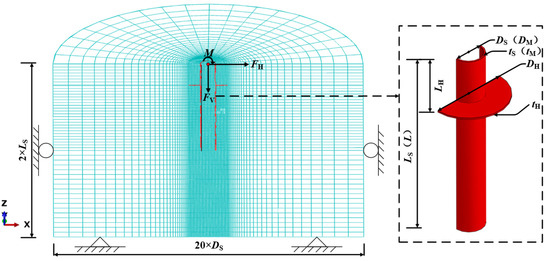
Figure 1.
Typical FE model and dimensions of the helical pile.
For the design of foundations for fixed offshore wind turbines, the first step is to estimate the maximum loads on the foundation due to all possible design load cases and compare them with the capacity of the chosen foundation [12]. In the service phase, foundations for fixed offshore wind turbines are normally subjected to a combination of vertical loading (FV) caused by the self-weight of the wind power structure, horizontal loading (FH), and moment loading (M) caused by wind, wave, and current. In the ocean, kaolinite clay is a common marine sediment [13] and is especially prevalent in the South China Sea [14]. Various studies, including centrifuge [15,16] and 1 g model tests [17,18], in situ tests [19,20,21], and numerical analyses [22,23] have investigated the bearing capacity of helical piles in kaolinite clay. However, most existing studies have focused only on uniaxial tensile loads, and the understanding of their performance under combined loading is limited. More research is necessary to fully examine their bearing capacity for offshore wind turbines.
In recent decades, the ultimate capacity of foundations under combined loading were assessed by a failure envelope approach, first introduced by Roscoe and Schofield [24], which defines the n-dimensional combination of loads (n ≥ 1) that results in the ultimate limit state (or plastic failure) of a foundation [25]. This assessment has been widely adopted to analyze the foundation bearing capacity for different foundation types, such as the bearing capacity of bucket foundations [26,27,28,29,30], that of spudcan foundations [31], that of monopile foundations [32], and that of mudmat foundations [33,34]. For helical piles, the failure envelope approach can be also treated as an option to assess their bearing capacity under combined loading.
This study employs the finite element software (ABAQUS) to conduct a failure envelope approach in order to assess the bearing capacity of helical piles under combined loading. To achieve this goal, the research team conducted 51 cases of the uniaxial bearing capacity of hollow shaft single-plate helical piles to illustrate the variation trend of the uniaxial bearing capacity and relevant failure mechanisms. Additionally, 561 analysis cases are carried out to construct the failure envelopes and develop formulas for predicting the bearing capacity of hollow shaft single-plate helical piles under combined loading.
2. Numerical Modelling Aspects
2.1. Geometries of Hollow Shaft Helical Piles and Soil Properties
Considering that almost 80% of foundations of fixed offshore wind turbines are steel-pipe piles [35], it is also treated as a reference. In addition, the size of the steel-pipe pile is the same as that of the shaft of the helical pile, and just hollow shaft single-plate helical piles are investigated in the present study. The hollow shaft single-plate helical piles consist of a hollow shaft and one helix and are treated as a rigid body. Considering the typical ratio between pitch and diameter of the helix should be just 1/20, according to the design guidance [1] for helical piles; the influence of pitch on the bearing capacity could be ignored and the helix is simplified as a circular plate. The geometry of a hollow shaft single-plate helical pile is specified by the outer diameter of the hollow shaft (DS), the diameter of the plate (DH), the distance from the bottom of the shaft to the soil surface (LS), the distance from the bottom of the plate to the soil surface (LH), the wall thickness of shaft (tS), and the thickness of plate (tH), as shown in Figure 1, considering the length-to-diameter aspect ratio of steel-pipe piles for offshore wind turbines is typically in the scope of 4~8 [36,37,38]. In this study, the length-to-diameter aspect ratio for the steel-pipe pile used as a comparison is set as six, The length of the steel-pipe pile (L), the outer diameter (DM) and the wall thickness (tM) of the steel-pipe pile were kept constant as 6 m, 1 m and 50 mm, respectively. The dimension of the hollow shaft for the helical pile is the same as that of the steel-pipe pile.
The elastic perfectly-plastic Tresca material is used to model soil. A uniform undrained shear strength (su), which is set equal to 10 kPa, is considered. The submerged effective unit weight of soil (γ’) is set equal to 6 kN/m3. The friction angle and dilation angle are both set at 0°. The Young’s modulus (E) and Poisson’s ratio (ν) are set as 5000 su and 0.49, respectively (to model undrained conditions with minimal volume change but maintain numerical stability). The relevant parameters about piles and soil are collected and shown in Table 1.

Table 1.
Summary of the parameters about piles and soil.
2.2. Finite Element Model
Three-dimensional finite-element modelling is carried out by using the finite element package ABAQUS [39]. Considering the symmetry of the structure and the load, a half model is used to improve the computation efficiency. As one typical FE model shown in Figure 1, the soil domain, which is a half cylinder, is set as 20 DS for diameter and 2 LS for height to avoid boundary effect [40]. For soil seabed, the bottom plane is fully fixed, the top plane is free and the outer side of the cylinder is constrained in the x and y directions. For the plane of symmetry, the movement in the normal direction is fixed. Eight-node linear hybrid brick element C3D8H [39] was adopted for soil and an eight-node linear brick element with reduced integration C3D8R is adopted for both the helical pile and steel-pipe pile.
The interface between a single-plate helical pile (or steel-pipe pile) with soil is defined by the mechanical contact properties, including normal and tangential behaviours of the contacting surface [41]. No separation is permitted in the normal direction to consider the influence of suction, and the tangential behaviour is simulated by Coulomb friction.
In order to obtain the ultimate bearing capacity and the relevant failure envelopes of the helical pile and steel-pipe pile, the displacement-control ‘probe test’ approach [28] was adopted by applying a given displacement at the reference point (RP) in this study. Two batches of probe tests are conducted in this study. The first batch is conducted to obtain the uniaxial ultimate bearing capacity of the steel-pipe pile and helical piles with different configurations by applying a displacement in the uniaxial direction without restricting the displacement in the other two directions. For the vertical, horizontal, and moment loads FV, FH, and M, and the corresponding displacement w, u, and θ, they are illustrated in Figure 1. The uniaxial bearing capacity factors NFV, NFH, and NM are expressed as the ultimate loadings FVult, FHult, and Mult normalized by the pile dimension (DS·LS or DS·LS·LS) and the soil shear strength, su, i.e., NFV = FVult/(DS·LS·su), NFH = FHult/(DS·LS·su), and NM = Mult/(DS·LS·LS·su). The second batch is conducted under different displacement ratios (w/u, w/θ, and u/θ) to obtain a series of failure points to characterize the failure envelope. To guarantee the accuracy and efficiency, the mesh sensitivity was conducted and the mesh used was found to represent a good balance between accuracy and computational efficiency. Fine meshes were used around the target pile to improve the accuracy of the analysis, where the minimum element size was DS/50, DS/5, and DS/10 in the target pile’s radial, embedment, and circumferential directions, respectively.
3. Results and Discussion
3.1. Model Validation
Considering the lack of a study about the bearing capacity of a hollow helical pile in clay, the validation of the model used in the present study is conducted by the comparison between current research results of steel-pipe pile with that of existing studies.
Five existing studies are used in the validation part and the bearing capacity factors in vertical and horizontal directions (NFV and NFH) are used as the standard of comparison. The length of the steel-pipe pile (L), the outer diameter (DM), and the wall thickness (tM) of the steel-pipe pile used for validation are constant at 6 m, 1 m, and 50 mm, respectively. The corresponding results are collected and shown in Table 2.
Table 2.
Comparison with current research results.
It can be seen from Table 2 that all deviations of the current results from the existing investigation do not exceed ±8.45%. Consequently, both numerical models of the helical pile and the steel-pipe pile are viable and will be used afterwards.
3.2. Uniaxial Ultimate Bearing Capacity
Parametric analysis is conducted in this section to investigate the effects of the helix-to-shaft diameter aspect ratio (DH/DS) and the position of the helix (LH/LS) on the uniaxial ultimate bearing capacity of helical piles and compared with that of monopile. A total of 51 cases of uniaxial bearing capacity are carried out, and the corresponding results are collected and shown in Table 3.
Table 3.
Analysis cases for uniaxial ultimate bearing.
3.2.1. Failure Mechanisms under Uniaxial Load
The effects of the helix-to-shaft diameter aspect ratio (DH/DS) and the position of the helix (LH/LS) on the failure mechanisms of helical piles under different uniaxial loads are discussed in this section. The typical results of the incremental displacement vectors and relevant contour plots of helical piles and pipe piles at failure under different uniaxial loads are illustrated in Figure 2 and Figure 3.
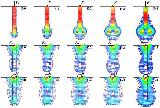
Figure 2.
The incremental displacement vectors and the relevant contour plots of the helical piles and the steel-pipe pile at failure under different uniaxial loads with different helix-to-shaft diameter aspect ratios (DH/DS).
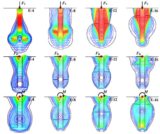
Figure 3.
The incremental displacement vectors and the relevant contour plots of the helical piles and the steel-pipe pile at failure under different uniaxial loads with different positions of the helix (LH/LS).
As shown in Figure 2, the failure mechanism of the steel-pipe pile under vertical load (E-0) is shaped as a downward-moving cylinder, the vertical displacement of soil located inside and bottom of the pipe pile is obvious, that of soil located outside of the pipe pile is unapparent. Under horizontal and moment loads, the steel-pipe pile (E-0) has the similar failure mechanism reported by Murff and Hamilton [46], which shows that the steel-pipe pile rotates along a rotation centre located on the steel-pipe pile, and two wedges, one behind the pile moving direction because of tension and one in front of a pile moving direction because of pushing, form near the soil surface. The difference between the mechanism of a steel-pipe pile under horizontal load and that under moment load is the position of the rotation centre and the following changes in the shape of the mechanism. The position of the rotation centre (~1/2 LS) under moment load is closer to the soil surface than that (~3/4 LS) under horizontal load.
The failure mechanisms of helical piles (E-1~E-4) with different helix-to-shaft diameter aspect ratios (DH/DS) vary from those of steel-pipe piles because of the presence of the plate. Under vertical load, the most distinctive difference between the failure mechanism of a steel-pipe pile with that of a helical pile is the additional interaction between soil and plate. The influence area gradually enlarges with the increase of the helix-to-shaft diameter aspect ratio (DH/DS), especially the compressive zone under the plate and the tensile region upside the plate, which extends to the position ~1/4 LS away from the soil surface. Under horizontal and moment loads, the shape of the influence area and the changing trend of the helical piles are similar to that of the steel-pipe pile. With the existence of the plate, more soil around the plate is motivated. This causes the enlarged influence area and the rotation centre movement towards the plate. The influence area enlarges and the position of the rotation centre moves downward with the increase of the helix-to-shaft diameter aspect ratio (DH/DS). For the influence of the position of the helix (LH/LS), some typical results are shown in Figure 3.
As illustrated in Figure 3, the position of the helix (LH/LS) also has a significant effect on the failure mechanisms of helical piles under different uniaxial loads. Under vertical load, the soil above the upper surface of the plate gradually moves down with the decrease of LH/LS, and the compressive zone under the plate gradually shrinks to the shaft. Under horizontal load, the shape of the influence area is similar to that of the steel-pipe pile but the position of the plate changes the position of the rotation centre and the influence area. With the decrease of LH/LS, the distance between the rotation centre and the plate decreases first, as shown in E-4 and E-8, and then increases, as shown in E-8, E-12, and E-16. The size of the influence area also has a similar changing trend and relation with the position of the rotation centre, it also decreases firstly, as shown in E-4 and E-8, and then increases, as shown in E-8, E-12, and E-16. The closer between the plate and the rotation centre, the smaller the influence area. Under moment load, the small influence area is also corresponding to the short distance between the plate and the rotation centre. Furthermore, the rotation center moves upward along with the plate.
3.2.2. Effect of the Helix-to-Shaft Diameter Aspect Ratio on Uniaxial Ultimate Bearing Capacity
The effect of the helix-to-shaft diameter aspect ratio (DH/DS) on pure uniaxial ultimate bearing capacity is analyzed in this section. The relevant load-displacement curves of helical piles and the steel-pipe pile under different uniaxial loads with different helix-to-shaft diameter aspect ratios (DH/DS) are shown in Figure 4.
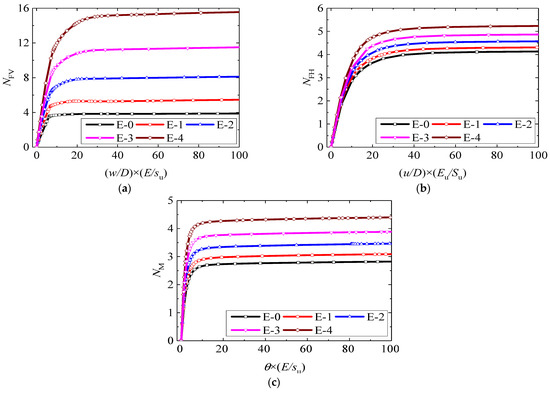
Figure 4.
The load-displacement curves of helical piles and steel-pipe pile under different uniaxial loads with different helix-to-shaft diameter aspect ratios (DH/DS): (a) Vertical load, (b) Horizontal load, (c) Moment load.
As shown in Figure 4, the displacement under different loading conditions normalized by the outer diameter of the steel-pipe pile (D), and soil stiffness ratio (E/su) [32,47] is the horizontal axis. For different uniaxial loads, they are characterized by the corresponding uniaxial bearing capacity factors NFV, NFH, and NM as the vertical axis, and the uniaxial bearing capacity is obtained when the gradient of the load-displacement curve approaches zero. For the steel-pipe pile, NFV, NFH, and NM are 3.9, 4.1, and 2.8, respectively. For helical piles, NFV are 5.5, 8.1, 11.5, and 15.6 when DH/DS = 1.5, 2, 2.5, and 3; NFH are 4.3, 4.6, 4.9, and 5.2 when DH/DS = 1.5, 2, 2.5 and 3; NM are 3.1, 3.5, 3.9 and 4.4 when DH/DS = 1.5, 2, 2.5 and 3. These results show that the uniaxial load-carrying properties of helical piles are better than that of the steel-pipe pile. To quantitatively denote the effect of the helix-to-shaft diameter aspect ratio (DH/DS) on the uniaxial bearing capacity of piles, the normalized capacity factors, (ηFV, the normalized vertical bearing capacity factor; ηFH, the normalized horizontal bearing capacity factor; ηM, the normalized moment bearing capacity factor), which are the ratio between the uniaxial bearing capacity factors of helical piles and that of the steel-pipe pile, are adopted. The corresponding results are collected and shown in Figure 5.
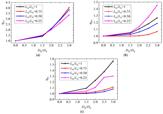
Figure 5.
The normalized capacity factors of helical piles and steel-pipe pile under different uniaxial loads with different helix-to-shaft diameter aspect ratio (DH/DS): (a) Vertical load, (b) Horizontal load, (c) Moment load.
It can be seen from Figure 5, the normalized capacity factors in different loading conditions all increase with the rise of DH/DS when LH/LS is fixed. However, the effect degree of DH/DS is different on different uniaxial ultimate bearing capacities, the degree of influence could be expressed by the sequence vertical > moment > horizontal. For example, when LH/LS = 1 and DH/DS changed from 0 to 3, the normalized capacity factors ηFV, ηFH, and ηM are changed from 1 to 4.0, 1.3, and 1.6, respectively.
3.2.3. Effect of the Position of Helix on Uniaxial Ultimate Bearing Capacity
To analyze the effect of the position of the helix (LH/LS) on uniaxial ultimate bearing capacity, the relevant normalized load-displacement curves of helical piles under different uniaxial loads with different positions of the helix (LH/LS) and those of monopile are collected and shown in Figure 6.
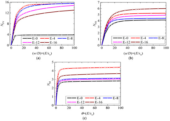
Figure 6.
The load-displacement curves of helical piles and steel-pipe pile under different uniaxial loads with different positions of the helix (LH/LS): (a) Vertical load, (b) Horizontal load, (c) Moment load.
As shown in Figure 6, the uniaxial load-carrying properties of helical piles are still much better than that of the steel-pipe pile when the plate is located in a different position. However, there is no obvious linear relationship between the corresponding uniaxial bearing capacity factors with LH/LS. When the DH/DS is fixed equal to 3, NFV are 15.6, 15.6, 14.8, and 13.0 with LH/LS = 1.0, 0.75, 0.5, and 0.25; NFH are 5.2, 4.4, 4.9, and 6.0 with LH/LS = 1.0, 0.75, 0.5, and 0.25; NM are 4.4, 3.1, 3.0; and 3.7 with LH/LS = 1.0, 0.75, 0.5 and 0.25. To quantitatively denote the effect of the position of the helix (LH/LS) on the uniaxial bearing capacity of piles, the corresponding normalized capacity factors, ηFV, ηFH, and ηM, are collected and shown in Figure 7.
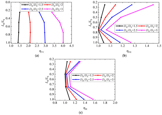
Figure 7.
The normalized capacity factors of helical piles and monopile under different uniaxial loads with different positions of the helix (LH/LS): (a) Vertical load, (b) Horizontal load, (c) Moment load.
It can be seen from Figure 7 that the relationship between the size of LH/LS and the changing amplitude of the normalized capacity factors ηFV, ηFH, and ηM is different from that shown in Figure 5. For ηFV, it has a trend that it gradually reduces with the decrease of LH/LS. This is because of the different failure mechanisms with different LH/LS and the corresponding different influence areas, as shown in Figure 3. For ηFH and ηM, as shown in Figure 3b,c, the nonlinear relationship between the size of LH/LS with them is obvious; the position of LH/LS = 0.75 could be treated as a critical point to distinguish positive and negative on ηFH and ηM. This behaviour is also corresponding to the failure mechanism shown in Figure 3, the relevant influence area under position LH/LS = 0.75 is smaller than that of the others. In addition, the position of the plate is nearest to the position of the rotation centre.
3.3. FV-FH-M Failure Envelopes
In this section, the effects of the helix-to-shaft diameter aspect ratio (DH/DS) and the position of the helix (LH/LS) on both the size and shape of the failure envelopes are systematically investigated. A total of 561 analysis cases, as collected and listed in Table 4, were conducted to obtain the failure points used to construct the failure envelopes. The corresponding results are collected and shown in Figure 8, Figure 9, Figure 10 and Figure 11.
Table 4.
The summary of analysis cases.
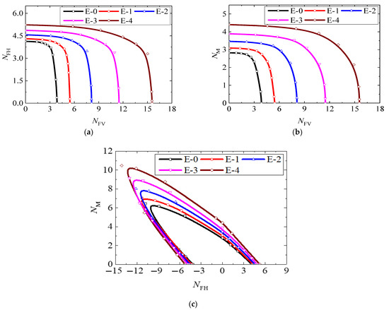
Figure 8.
Typical results of dimensionless failure envelopes with different helix-to-shaft diameter aspect ratios (DH/DS): (a) FV-FH failure envelope, (b) FV-M failure envelope, (c) FH-M failure envelope.
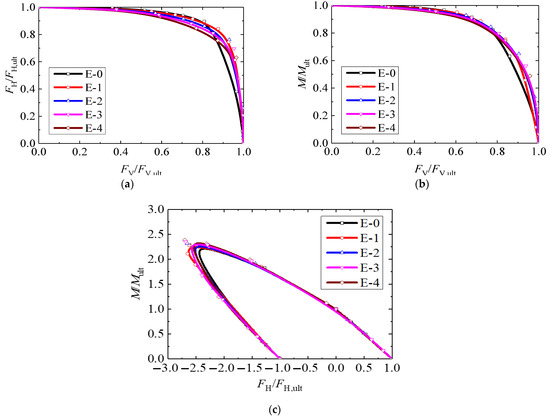
Figure 9.
Typical results of the normalized failure envelopes with different helix-to-shaft diameter aspect ratio (DH/DS): (a) FV-FH failure envelope, (b) FV-M failure envelope, (c) FH-M failure envelope.
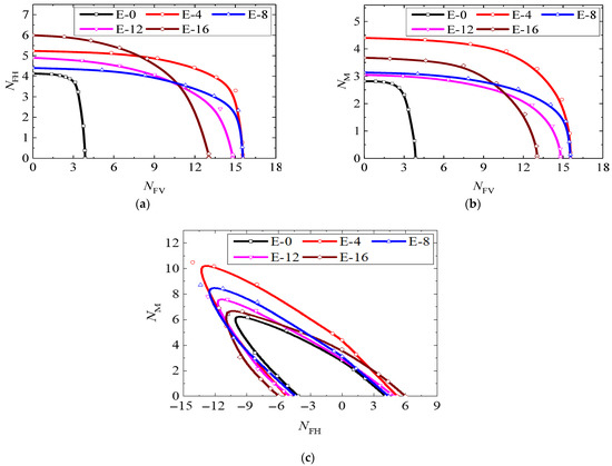
Figure 10.
Dimensionless failure envelopes with different positions of the helix (LH/LS): (a) FV-FH failure envelope, (b) FV-M failure envelope, (c) FH-M failure envelope.
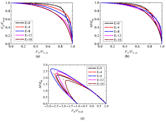
Figure 11.
Normalized failure envelopes with different positions of the helix (LH/LS): (a) FV-FH failure envelope, (b) FV-M failure envelope, (c) FH-M failure envelope.
3.3.1. Effect of the Helix-to-Shaft Diameter Aspect Ratio on Failure Envelopes
In order to investigate the effect of the helix-to-shaft diameter aspect ratio (DH/DS) on the load-carrying property of helical piles and the steel-pipe pile under combined loading, the corresponding dimensionless failure envelopes are illustrated in Figure 8.
As shown in Figure 8, the sizes of envelopes for helical piles under different loading combinations all increase with the increase of DH/DS. For the horizontal and moment capacities of helical piles and the steel-pipe pile, both decrease obviously with the increase of vertical force, as shown in Figure 8a,b. For the FH-M failure envelopes of helical piles and the steel-pipe pile shown in Figure 8c, they have a similar unsymmetrical shape; this is because of the adverse coupling effect of FH and M in different directions. For further investigation about the effect of DH/DS on the shape of failure envelopes, the corresponding failure envelopes are normalized and shown in Figure 9.
It can be seen from Figure 9, the normalized FV-FH failure envelope shrinks inwards as the helix-to-shaft diameter aspect ratio (DH/DS) increases, and the shape of the normalized FV-FH, FH-M, and FH-M failure envelopes almost keeps constant.
3.3.2. Effect of the Position of Helix on Failure Envelopes
In order to investigate the effect of the position of the helix (LH/LS) on the load-carrying property of helical piles and steel-pipe pile under combined loading, the dimensionless failure envelopes are illustrated in Figure 10.
As shown in Figure 10, the effect of the position of the helix (LH/LS) on failure envelopes is more complex than that of the helix-to-shaft diameter aspect ratio (DH/DS) and the corresponding failure envelopes under different loading combinations all have the overlapping condition. This is because of the nonlinear relationship between the size of LH/LS with ηFH and ηM, as shown in Figure 3b,c, and the failure mechanism under combined loading should be more complex. When the amount of steel used for the manufacturing of a helical pile (under constant DH/DS with fixed shaft) is constant, the position of the plate (LH/LS) could adjust the uniaxial ultimate bearing capacity under different directions and the ratio between each other. It is worth noting that the FH-M failure envelope expands outwards with the increase of LH/LS and the behaviour of the helical pile with a plate on the bottom of the shaft (E-4) is best under FV-M and FH-M combined loading conditions. For further investigation about the effect of the position of the plate (LH/LS) on the shape of failure envelopes, the corresponding failure envelopes are normalized and shown in Figure 11.
It is illustrated in Figure 11 that the position of the helix (LH/LS) has a significant effect on the shape of failure envelopes. For the normalized FV-FH failure envelope, it gradually shrinks with the decrease of LH/LS. However, the law of variation for the normalized FV-M and FH-M failure envelopes are relatively vague.
3.3.3. The Establishment of Failure Envelopes
To quantitatively evaluate the effect of the helix-to-shaft diameter aspect ratio (DH/DS) and the position of the helix (LH/LS) on both the size and shape of the failure envelopes and predict the bearing capacity of hollow shaft single-plate helical piles under combined loading, an equation modified from that in Cassidy et al. [48] and Zhang et al. [31] is proposed below.
where are fitting parameters used to determine the shape and size of the failure envelope and the corresponding values of these parameters under different conditions are collected and shown in Table 5.
Table 5.
Summary of the parameters used to define failure envelopes.
Based on the results in Table 5, the relevant formulas for evaluating these fitting parameters are developed and written as Equation (2).
Based on the equation of the failure envelope, and that of corresponding fitting parameters, the typical results about E-1 and E-12 are shown in Figure 12. As shown in Figure 12, the agreement between the original bearing capacity points between the failure envelopes expressed by Equations (1) and (2) are good. The maximum error is not more than 4%.
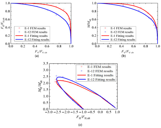
Figure 12.
The typical fitted normalized failure envelopes for E-1 and E-12: (a) FV-FH failure envelope, (b) FV-M failure envelope, (c) FH-M failure envelope.
4. Conclusions
In order to predict the bearing capacity of hollow shaft single-plate helical piles under combined loading, a total of 561 cases under different loading conditions were conducted through 3D FEM to investigate the relevant failure envelopes, considering the effect of the helix-to-shaft diameter aspect ratio (DH/DS) and the position of the helix (LH/LS). The relevant results were also compared with that of a steel-pipe pile. Based on the present study, it could be found that:
Helical piles have greater uniaxial ultimate bearing capacity compared with a steel-pipe pile which has the same size as the shaft of a helical pile. This phenomenon is caused by the larger influence area due to the existence of the helix. The uniaxial ultimate bearing capacity of a helical pile in different directions will increase as DH/DS increases, while LH/LS remains unchanged. When the helix-to-shaft diameter aspect ratio (DH/DS) remains unchanged, the position of the helix (LH/LS) has a significant effect on the corresponding failure mode and the uniaxial ultimate bearing capacity of the helical pile has a nonlinear relationship with the size of LH/LS.
For the effect of DH/DS and LH/LS on the envelope, they show a significant difference. For the shape of the normalized failure envelopes, DH/DS is almost no influence on them; on the contrary, the effect of LH/LS on them is obvious. For the size of the dimensionless failure envelope, the effect of DH/DS is a linear positive effect; however, LH/LS causes the nonlinear positive effect on failure envelopes. Based on the systematic analysis of the load-carrying properties of helical piles, a formula was proposed to predict corresponding failure envelopes and the accuracy of this formula is also tested. The bearing capacity of hollow shaft single-plate helical piles under combined loading could be evaluated by the expressions of failure envelopes. Further, due to the specificity of the marine environment, the cyclic loading condition caused by wind, wave, and current also needs to be considered in the future study.
Author Contributions
Conceptualization, L.W., X.Z. and H.D.; methodology, L.W., X.Z. and P.Z.; software, L.W. and X.Z.; validation, L.W., X.Z. and M.L.; formal analysis, L.W.; investigation, P.Z. and Y.T.; resources, L.W.; data curation, X.Z.; writing—original draft preparation, X.Z.; writing—review and editing, L.W.; visualization, L.W.; supervision, Y.G.; project administration, H.D.; funding acquisition, L.W. All authors have read and agreed to the published version of the manuscript.
Funding
This research was supported by the National Natural Science Foundation of China under Grant (NSFC 51890913, 52209090). The first and seventh authors appreciate the support from the State Key Laboratory of Hydraulic Engineering Simulation and Safety, Tianjin University (HESS-2019) and the State Key Laboratory of Coastal and Offshore Engineering, Dalian University of Technology (LP2120).
Institutional Review Board Statement
Not applicable.
Informed Consent Statement
Not applicable.
Data Availability Statement
Not applicable.
Conflicts of Interest
The authors declare no conflict of interest.
Notation List
| DS | The outer diameter of hollow shaft |
| DM | The outer diameter of steel-pipe pile |
| DH | The outer diameter of helix or plate |
| LS | The distance from the bottom of shaft to soil surface |
| L | The length of steel-pipe pile |
| LH | The distance from the bottom of helix to soil surface |
| tS | The wall thickness of hollow shaft |
| tM | The wall thickness of steel-pipe pile |
| tH | The thickness of helix |
| FV | The vertical load for piles |
| FH | The horizontal load for piles |
| M | The moment load for piles |
| w | The vertical displacement for piles |
| u | The horizontal displacement for piles |
| θ | The rotation angle for piles |
| FV,ult | The vertical ultimate bearing capacity for piles |
| FH,ult | The horizontal ultimate bearing capacity for piles |
| Mult | The moment ultimate bearing capacity for piles |
| NFV | The vertical bearing capacity factor |
| NFH | The horizontal bearing capacity factor |
| NM | The moment bearing capacity factor |
| ηFV | The normalized vertical bearing capacity factor |
| ηFH | The normalized horizontal bearing capacity factor |
| ηM | The normalized moment bearing capacity factor |
| su | The undrained shear strength of soil |
| E | The Young’s modulus of soil |
| γ’ | The submerged effective unit weight of soil |
References
- Perko, H. Helical piles. In A Practical Guide to Design and Installation, 1st ed.; John Wiley & Sons: Hoboken, NJ, USA, 2009. [Google Scholar]
- Lutenegger, A. Historical development of iron screw-pile foundations: 1836–1900. Int. J. Hist. Eng. Technol. 2011, 81, 108–128. [Google Scholar] [CrossRef]
- Schiavon, J. Comportamento de Ancoragens helicoidais Submetidas a Carregamentos Cíclicos. Ph.D. Thesis, University of São Paulo, São Paulo, Brazil, 2016. [Google Scholar]
- Komatsu, A. Development on battered pile with screw pile method (NS-ECO pile). In Advances in Deep Foundations; Kikuchi, Y., Otani, J., Kimura, M., Morikawa, Y., Eds.; Taylor & Francis: London, UK, 2007; pp. 253–257. [Google Scholar]
- Hernandez, C.; Shadman, M.; Maali, A.; Silva, C.; Estefen, S.F.; La Rovere, E. Environmental impacts of offshore wind installation, operation and maintenance, and decommissioning activities: A case study of Brazil. Renew. Sustain. Energy Rev. 2021, 144, 110994. [Google Scholar] [CrossRef]
- Hao, D.; Wang, D.; O’Loughlin, C.D.; Gaudin, C. Tensile monotonic capacity of helical anchors in sand: Interaction between helices. Can. Geotech. J. 2019, 56, 1534–1543. [Google Scholar] [CrossRef]
- Cerfontaine, B.; Knappett, J.; Brown, M.J.; Davidson, C.; Al-Baghdadi, T.; Sharif, Y.; Brennan, A.; Augarde, C.E.; Coombs, W.M.; Wang, L.; et al. A finite element approach for determining the full load-displacement relationship of axially-loaded screw anchors, incorporating installation effects. Can. Geotech. J. 2021, 58, 565–582. [Google Scholar] [CrossRef]
- Wang, L.; Zhang, P.; Ding, H.; Tian, Y.; Qi, X. The uplift capacity of single-plate helical pile in shallow dense sand including the influence of installation. Mar. Struct. 2020, 71, 102697. [Google Scholar] [CrossRef]
- Byrne, B.; Houlsby, G.T. Helical piles: An innovative foundation design option for offshore wind turbines. Philos. Trans. Royal Soc. A Math. Phys. Eng. Sci. 2015, 373, 20140081. [Google Scholar] [CrossRef]
- Spagnoli, G.; De Hollanda, C.; Tsuha, C. A review on the behavior of helical piles as a potential offshore foundation system. Mar. Georesources Geotechnol. 2020, 38, 1013–1036. [Google Scholar] [CrossRef]
- Ullah, S.; Hu, Y. Discussion: A review on the behaviour of helical piles as a potential offshore foundation system. Mar. Georesources Geotechnol. 2020, 38, 1121–1127. [Google Scholar] [CrossRef]
- DNVGL-ST-0126; Support Structures for Wind Turbines. DNVGL: Bærum, Norway, 2018.
- O’Loughlin, C.D.; Neubecker, S.R.; Gaudin, C. Anchoring systems: Anchor types, installation and design. In Encyclopaedia of Marine and Offshore Engineering; Wiley: Hoboken, NJ, USA, 2018. [Google Scholar]
- Liu, Z.; Zhao, Y.; Colin, C.; Stattegger, K.; Wiesner, M.G.; Huh, C.-A.; Zhang, Y.; Li, X.; Sompongchaiyakul, P.; You, C.F.; et al. Source-to-sink transport processes of fluvial sediments in the South China Sea. Earth-Sci. Rev. 2016, 153, 238–273. [Google Scholar] [CrossRef]
- Li, W.; Deng, L.; Chalaturnyk, R. Centrifuge modeling of the behaviour of helical piles in cohesive soils from installation and axial loading. Soils Found. 2022, 62, 101141. [Google Scholar] [CrossRef]
- Wang, D.; Merifield, R.S.; Gaudin, C. Uplift behaviour of helical anchors in clay. Can. Geotech. J. 2013, 50, 575–584. [Google Scholar] [CrossRef]
- Rao, S.; Prasad, Y.; Shetty, M. The behaviour of model screw piles in cohesive soils. Soils Found. 1991, 31, 35–50. [Google Scholar] [CrossRef] [PubMed]
- Rao, S.; Prasad, Y.; Veeresh, C. Behaviour of embedded model screw anchors in soft clays. Geotechnique 1993, 43, 605–614. [Google Scholar] [CrossRef]
- Sakr, M. Relationship between Installation Torque and Axial Capacities of Helical Piles in Cohesive Soils. DFI J. J. Deep Found. Inst. 2013, 7, 44–58. [Google Scholar] [CrossRef]
- Lanyi-Bennett, S.; Deng, L. Axial load testing of helical pile groups in glaciolacustrine clay. Can. Geotech. J. 2019, 56, 187–197. [Google Scholar] [CrossRef]
- Lanyi-Bennett, S.; Deng, L. Effects of inter-helix spacing and short-term soil setup on the behaviour of axially loaded helical piles in cohesive soil. Soils Found. 2019, 59, 337–350. [Google Scholar] [CrossRef]
- Merifield, R. Ultimate Uplift Capacity of Multiplate Helical Type Anchors in Clay. J. Geotech. Geoenvironmental Eng. 2011, 137, 704–716. [Google Scholar] [CrossRef]
- Zhou, H.; Hu, Q.; Yu, X.; Zheng, G.; Liu, X.; Xu, H.; Yang, S.; Liu, J.; Tian, K. Quantitative bearing capacity assessment of strip footings adjacent to two-layered slopes considering spatial soil variability. Acta Geotechnica 2023. [Google Scholar] [CrossRef]
- Roscoe, K.; Schofield, A.N. The stability of short pier foundations in sand. Br. Weld. J. 1956, 3, 343–354. [Google Scholar]
- Suryasentana, S.; Dunne, H.; Martin, C.; Burd, H.; Byrne, B.; Shonberg, A. Assessment of numerical procedures for determining shallow foundation failure envelopes. Géotechnique 2019, 70, 60–70. [Google Scholar] [CrossRef]
- Zhao, X.; Zhang, P.; Lv, Y.; Ding, H. Scour effects on bearing capacity of composite bucket foundation for offshore wind turbines. Mar. Georesources Geotechnol. 2020, 38, 223–237. [Google Scholar] [CrossRef]
- Jing, Y.; Wang, Y.; Huang, Q.; Wang, W.; Luo, L. Failure envelopes of composite bucket foundation for offshore wind turbines under combined loading with considering different scour depths. Shock Vib. 2021, 2021, 7922572. [Google Scholar] [CrossRef]
- Bransby, M.; Randolph, M.F. Combined loading of skirted foundations. Géotechnique 1998, 48, 637–655. [Google Scholar] [CrossRef]
- Gourvenec, S.; Barnett, S. Undrained failure envelope for skirted foundations under general loading. Géotechnique 2011, 61, 263–270. [Google Scholar] [CrossRef]
- Karapiperis, K.; Gerolymos, N. Combined loading of caisson foundations in cohesive soil: Finite element versus Winkler modeling. Comput. Geotech. 2014, 56, 100–120. [Google Scholar] [CrossRef]
- Zhang, Y.; Bienen, B.; Cassidy, M.J.; Gourvenec, S. The undrained bearing capacity of a spudcan foundation under combined loading in soft clay. Mar. Struct. 2011, 24, 459–477. [Google Scholar] [CrossRef]
- Guo, X.; Liu, J.; Feng, X.; Han, C. Effects of local scour on failure envelopes of offshore monopiles and caissons. Appl. Ocean Eng. 2022, 118, 103007. [Google Scholar] [CrossRef]
- Feng, X.; Randolph, M.; Gourvenec, S.; Wallerand, R. Design approach for rectangular mudmats under fully three-dimensional loading. Géotechnique 2014, 64, 51–63. [Google Scholar] [CrossRef]
- Dunne, H.; Martin, C. Capacity of rectangular mudmat foundations on clay under combined loading. Géotechnique 2017, 67, 168–180. [Google Scholar] [CrossRef]
- Negro, V.; López-Gutiérrez, J.; Esteban, M.D.; Alberdi, P.; Imaz, M.; Serraclara, J.M. Monopiles in offshore wind: Preliminary estimate of main dimensions. Ocean Eng. 2017, 133, 253–261. [Google Scholar] [CrossRef]
- Lombardi, D.; Bhattacharya, S.; Wood, D.M. Dynamic soil-structure interaction of monopile supported wind turbines in cohesive soil. Soil Dyn. Earthq. Eng. 2013, 49, 165–180. [Google Scholar] [CrossRef]
- Cui, C.; Zhang, S.; David, C.; Kun, M. Dynamic impedance of a floating pile embedded in poro-visco-elastic soils subjected to vertical harmonic loads. Geomechanics and Engineering. 2018, 15, 793–803. [Google Scholar]
- Tseng, W.; Kuo, Y.; Chen, J. An investigation into the effect of scour on the loading and deformation responses of monopile foundations. Energies 2017, 10, 1190. [Google Scholar] [CrossRef]
- Dassault Systèmes. Abaqus Analysis User’s Manual; Simulia: Providence, RI, USA, 2016. [Google Scholar]
- Deb, P.; Pal, S. Numerical analysis of piled raft foundation under combined vertical and lateral loading. Ocean Eng. 2019, 190, 106431.1–104431.13. [Google Scholar] [CrossRef]
- Kong, D.; Liu, Y.; Deng, M.; Zhao, X. Analysis of influencing factors of lateral soil resistance distribution characteristics around monopile foundation for offshore wind power. Appl. Ocean Res. 2020, 97, 102106. [Google Scholar] [CrossRef]
- Tan, M. Bearing Capacity of Rectangular Plate Anchor/Foundations in Normally Consolidated Clay. Ph.D. Thesis, Dalian University of Technology, Dalian, China, 2018. [Google Scholar]
- API (American Petroleum Institute). Geotechnical and Foundation Design Considerations API RP 2GEO; American Petroleum Institute: Washington, DC, USA, 2011. [Google Scholar]
- Randolph, M.; Neill, M.; Stewart, D.; Erbrich, C. Performance of suction anchors in fine-grained calcareous soils. Geology 1998, OTC8831, 521–529. [Google Scholar]
- Aubeny, C.; Han, S.; Murff, J. Inclined load capacity of suction caissons. Int. J. Numer. Anal. Methods Geomech. 2003, 27, 1235–1254. [Google Scholar] [CrossRef]
- Murff, J.; Hamilton, J. P-ultimate for undrained analysis of laterally loaded piles. J. Geotech. Eng. 1993, 119, 91–107. [Google Scholar] [CrossRef]
- Hu, Y.; Randolph, M.F. Bearing capacity of caisson foundations on normally consolidated clay. Soils Found. 2002, 42, 71–77. [Google Scholar] [CrossRef]
- Cassidy, M.; Uzielli, M.; Tian, Y. Probabilistic combined loading failure envelopes of a strip footing on spatially variable soil. Comput. Geotech. 2012, 49, 191–205. [Google Scholar] [CrossRef]


Disclaimer/Publisher’s Note: The statements, opinions and data contained in all publications are solely those of the individual author(s) and contributor(s) and not of MDPI and/or the editor(s). MDPI and/or the editor(s) disclaim responsibility for any injury to people or property resulting from any ideas, methods, instructions or products referred to in the content. |
© 2023 by the authors. Licensee MDPI, Basel, Switzerland. This article is an open access article distributed under the terms and conditions of the Creative Commons Attribution (CC BY) license (https://creativecommons.org/licenses/by/4.0/).