
Aerodynamic Performance of Vertical-Axis Wind Turbines
 , ,
, , 
Abstract
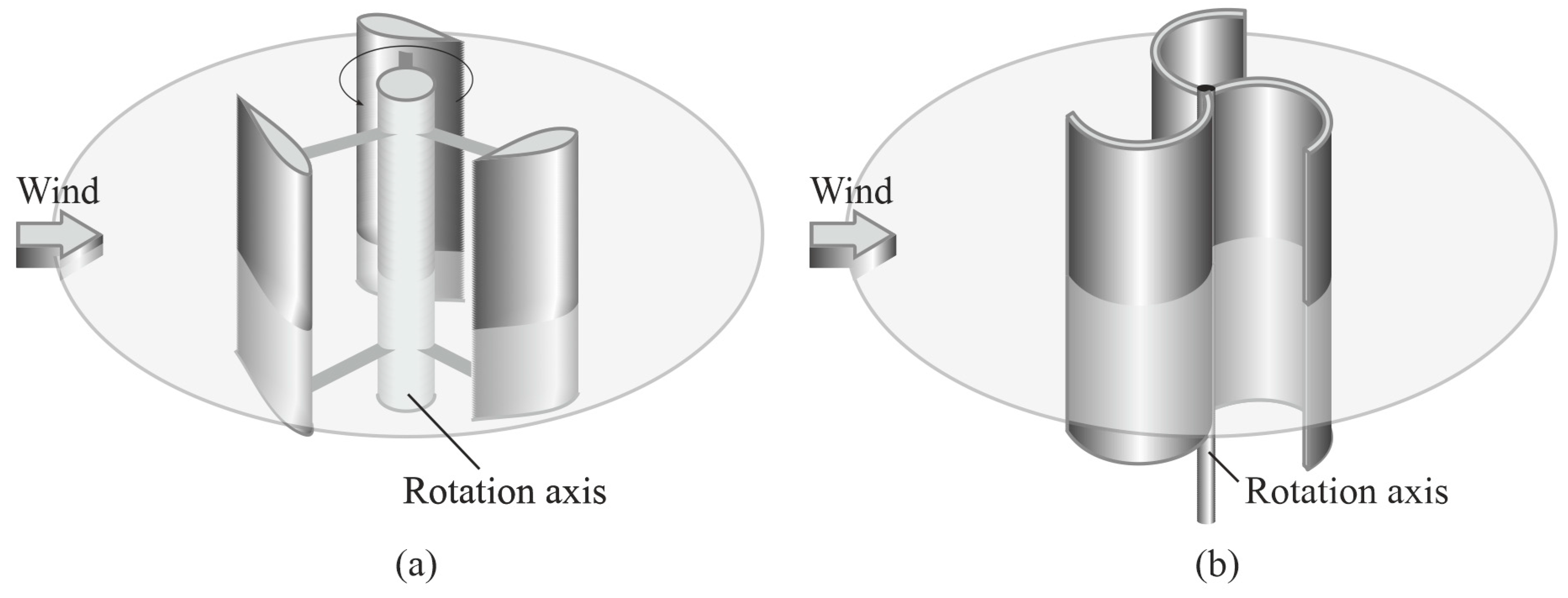
:1. Introduction
- I.
- Engineering, empirical technique;
- II.
- Inviscid gas model—The potential and Euler equations;
- III.
- Viscous gas model with averaging turbulent characteristics (RANS equations);
- IV.
- Viscous gas models with unsteady turbulent characteristics (DES, LES, DNS approaches).
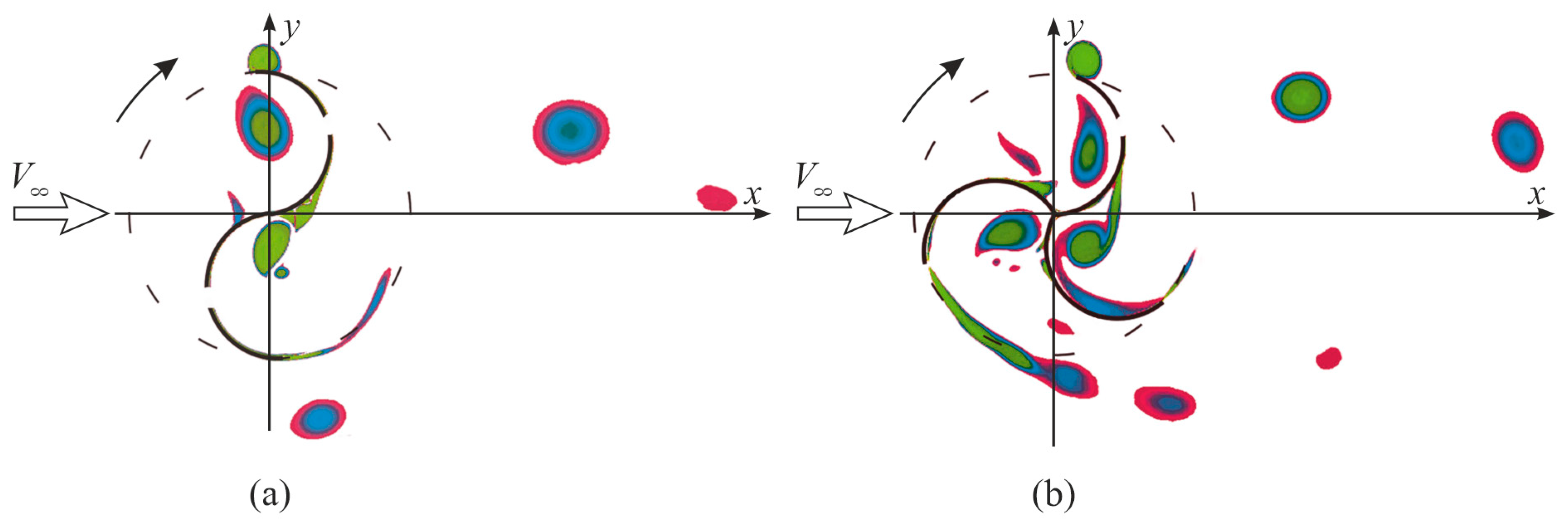
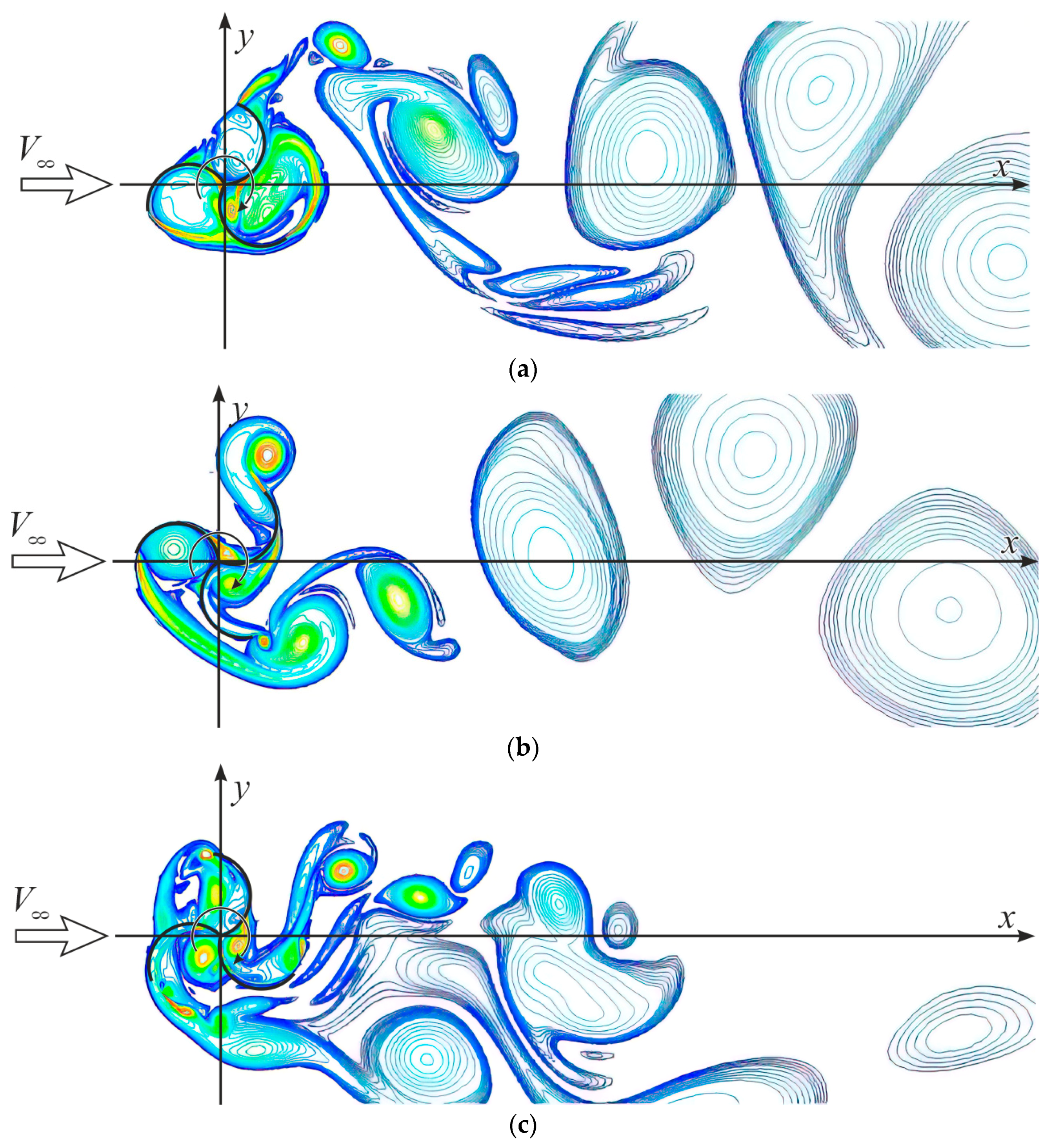
- The regularities of the development of the unsteady flow around Darrieus and Savonius rotors with different number of blades have been revealed.
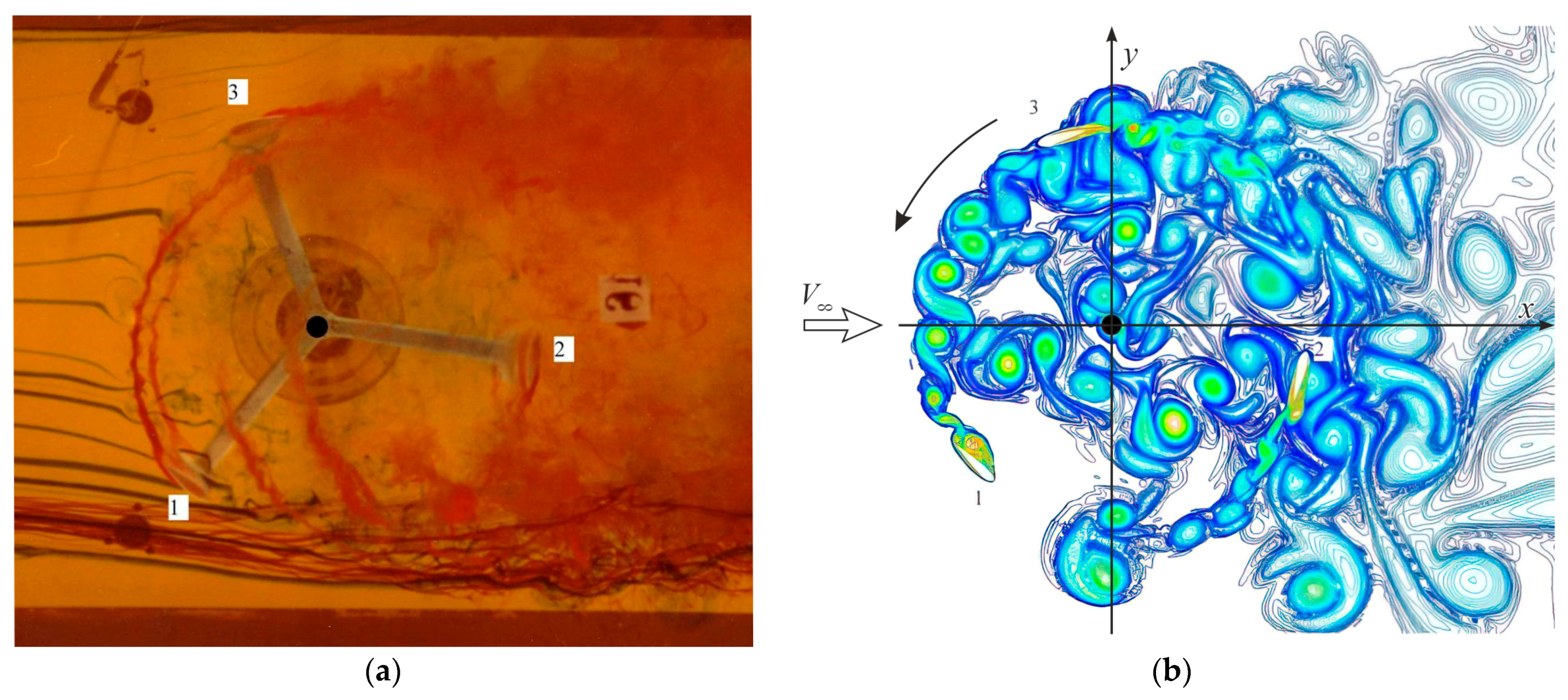
- Qualitative comparisons of the flow pattern around a two- and three-blade Darrieus rotor with experimental data were carried out.
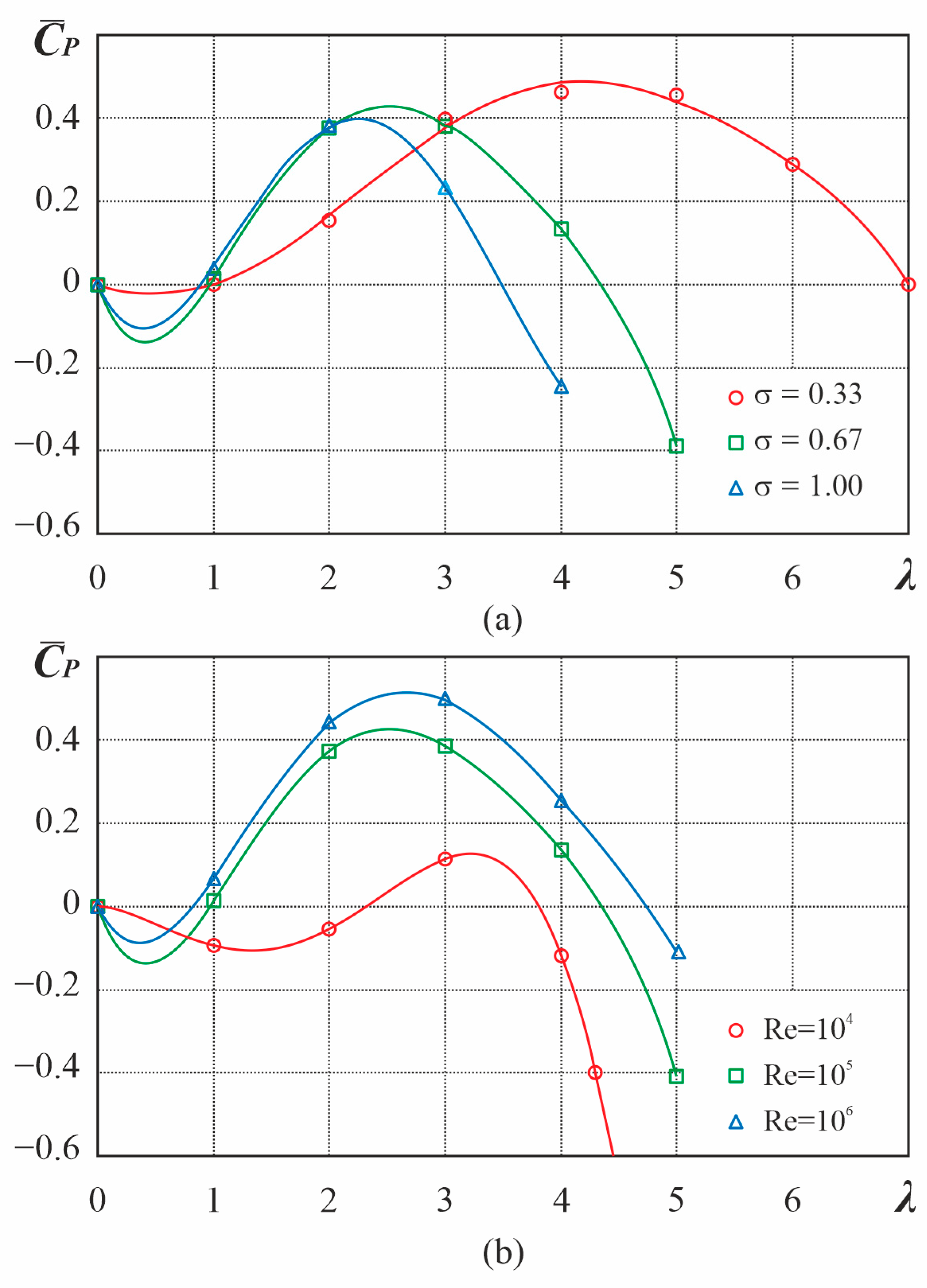
- The dependences of the power coefficient of the VAWT rotors on the Reynolds number, tip-speed ratio, and solidity are determined.
- The influence of the Reynolds number on the dynamic stall from the blades and the Darrieus rotor power coefficient is determined.
- The influence of the solidity and the tip-speed ratio on the power characteristics of the Darrieus rotor is determined.
- The influence of the blades number and Reynolds number on the power characteristics of the Savonius rotor is determined.
2. Methodology
2.1. Mathematical Model
2.2. Turbulence Model
2.3. Boundary Conditions
3. Numerical Setup
3.1. Numerical Algorithm
3.2. Developed CFD Code
- -
- the main task of the specialized package is to simulate the flow field numerically with maximum physical veracity;
- -
- specialization of the package and the efficiency of solving this class of problems;
- -
- no need to buy or rent expensive commercial packages.
4. Results and Discussion
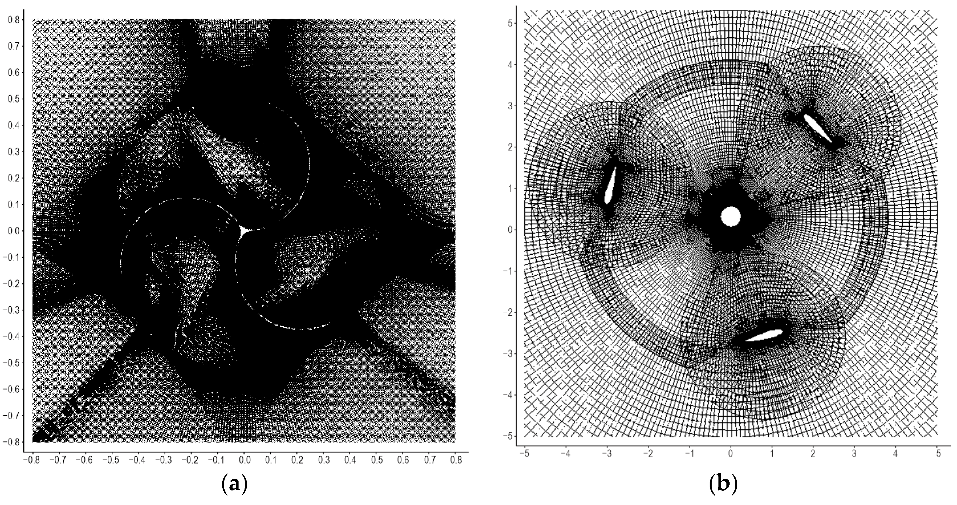
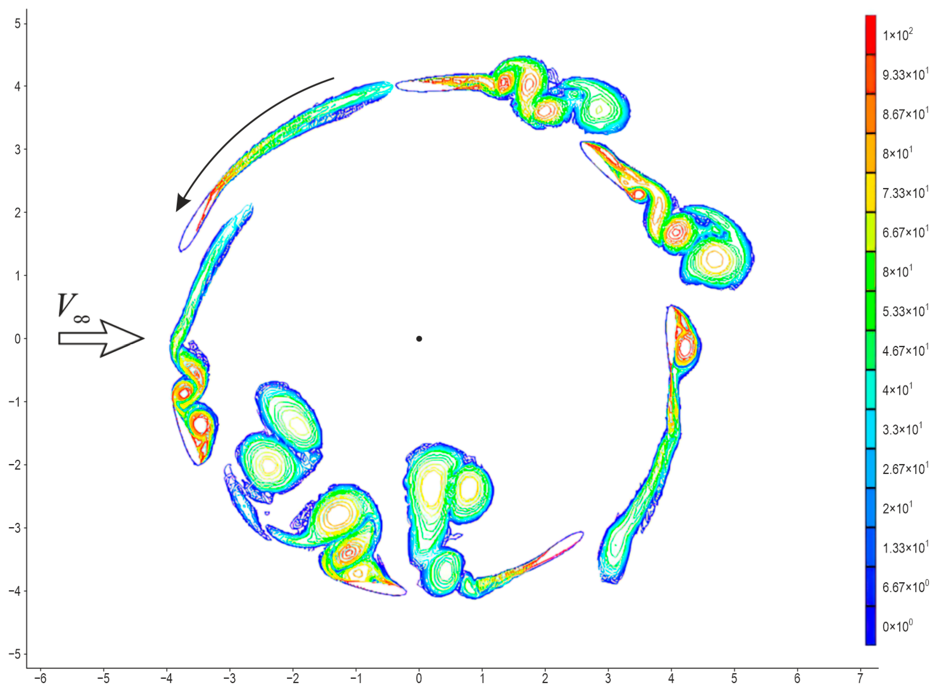
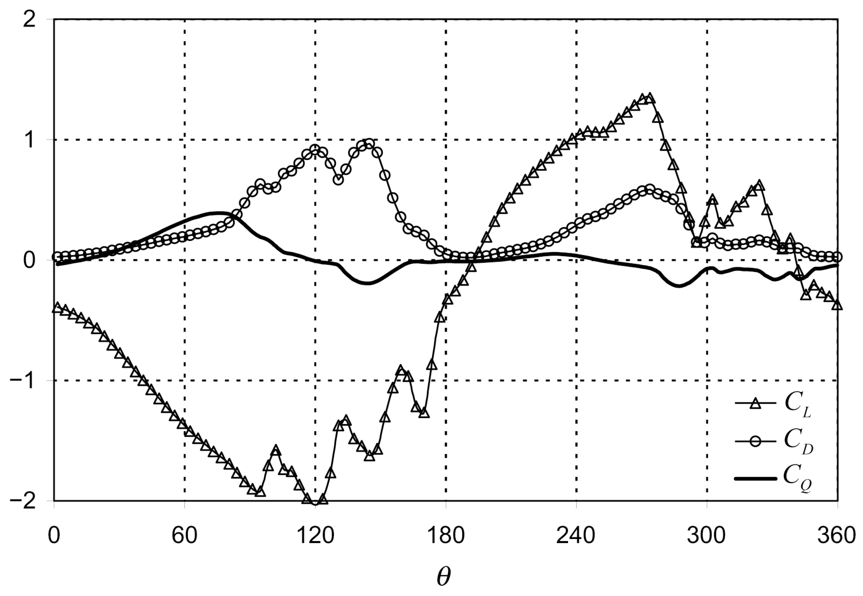
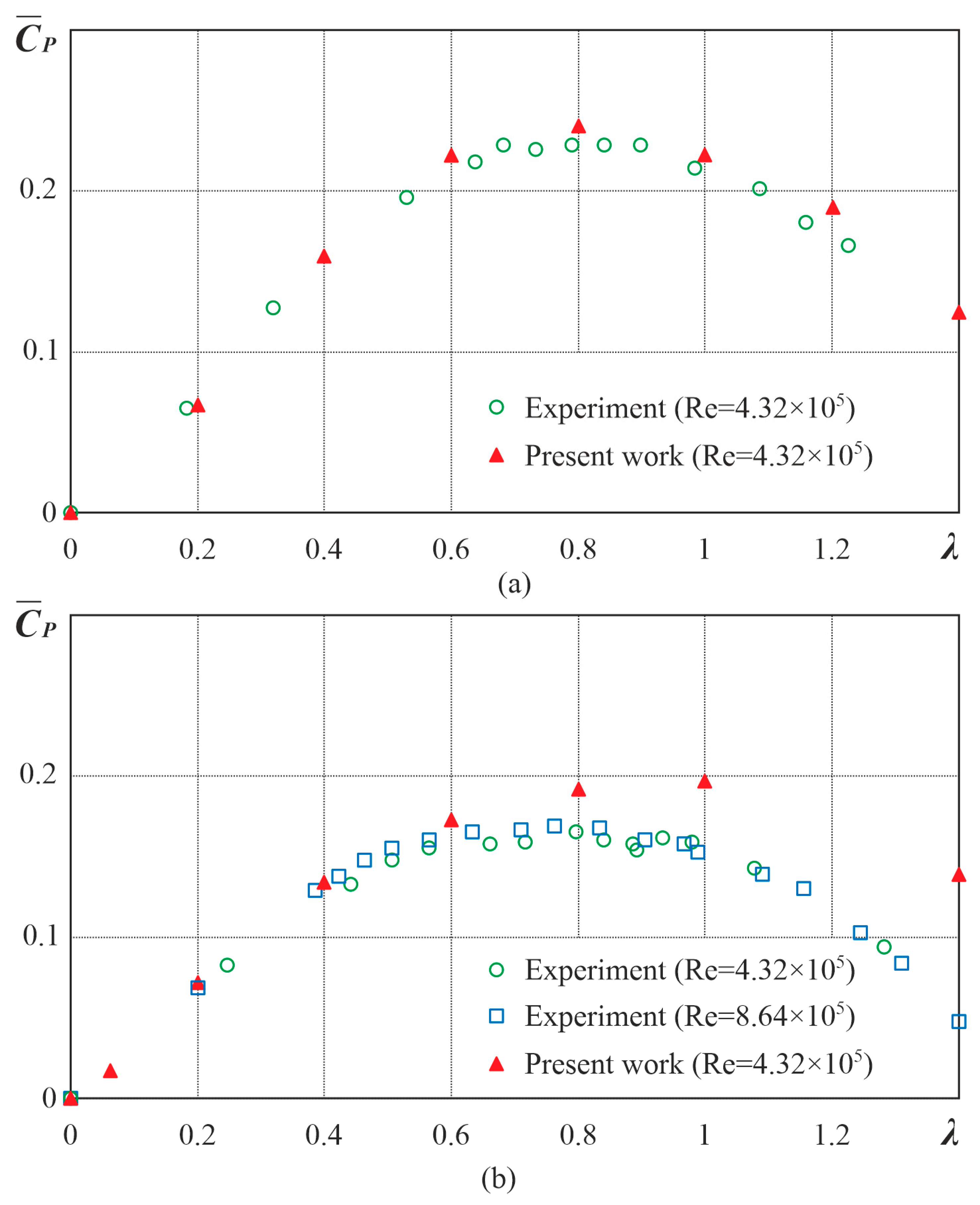
4.1. Darrieus Rotor
- -
- Blade airfoil—NACA 0018;
- -
- Tip-speed ratio—;
- -
- Reynolds number on the rotor diameter—, , ;
- -
- Solidity—, , .
4.2. Savonius Rotor
5. Conclusions
Author Contributions
Funding
Informed Consent Statement
Data Availability Statement
Acknowledgments
Conflicts of Interest
References
- Electricity Information. 2019. Available online: https://www.iea.org (accessed on 5 June 2023).
- Global Wind Report (GWEC). 2019. Available online: https://gwec.net/global-wind-report (accessed on 5 June 2023).
- Darrieus, G.J.M. Turbine Having Its Rotating Shaft Traverse to the Flow of the Current. U.S. Patent 1,835,018, 8 December 1931. [Google Scholar]
- Eriksson, S.; Bernhoff, H.; Leijon, M. Evaluation of different turbine concepts for wind power. Renew. Sustain. Energy Rev. 2008, 12, 1419–1434. [Google Scholar] [CrossRef]
- Paraschivoiu, I. Wind Turbine Design with Emphasis on Darrieus Concept; Polytechnic International Press: Burlington, ON, Canada, 2002. [Google Scholar]
- Longhuan, D.; Grant, I.; Robert, D. A review of H-Darrieus wind turbine aerodynamic research. J. Mech. Eng. Sci. 2019, 233, 7590–7616. [Google Scholar]
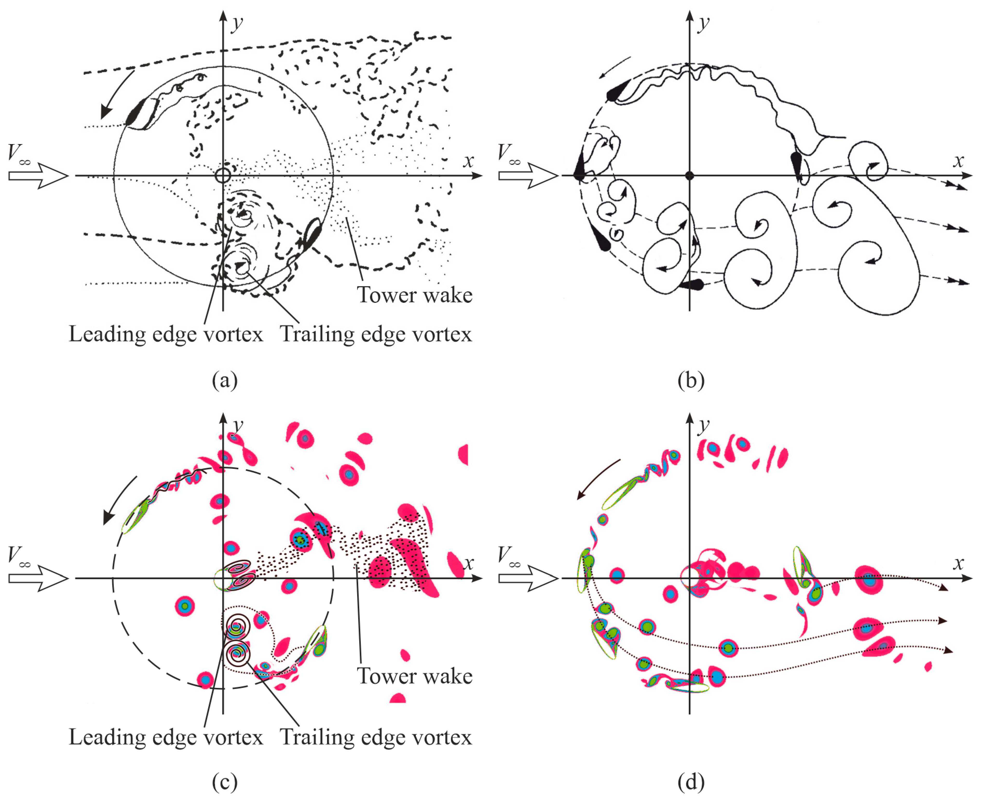
- Brochier, G.; Fraunie, P.; Beguier, C.; Paraschivoiu, I. Water channel experiments of dynamic stall on Darrieus wind turbine blades. J. Propuls. 1986, 5, 445–449. [Google Scholar] [CrossRef]
- Hu, Y.; Wang, T.; Jin, H.; Cao, X.; Zhang, C. Experimental study on aerodynamic characteristics of vertical-axis wind turbine. Int. J. Smart Grid Clean Energy 2017, 2, 104–113. [Google Scholar] [CrossRef]
- Strickland, J.H.; Webster, B.T.; Nguyen, T. Vortex model of the Darrieus turbine: An analytical and experimental study. NASA STI/Recon Tech. Rep. N 1980, 80, 25887. [Google Scholar] [CrossRef]
- Biadgo, A.; Simonovic, A.; Komarov, D.; Stupar, S. Numerical and Analytical Investigation of Vertical Axis Wind Turbine. FME Trans. 2013, 1, 132–150. [Google Scholar]
- Sun, X.; Wang, Y.; An, Q.; Cao, Y.; Wu, G.; Huang, D. Aerodynamic performance and characteristic of vortex structures for Darrieus wind turbine. II. The relationship between vortex structure and aerodynamic performance. J. Renew. Sustain. Energy 2014, 6, 043135. [Google Scholar] [CrossRef]
- Madina, F.G.; Gutiérrez, A.; Galione, P. Computational fluid dynamics study of Savonius rotors using OpenFOAM. Wind. Eng. 2020, 45, 630–647. [Google Scholar] [CrossRef]
- Savonius, S.J. Wind Rotor. U.S. Patent 1,766,765, 24 June 1930. [Google Scholar]
- Abkar, M.; Dabiri, J.O. Self-similarity and flow characteristics of vertical-axis wind turbine wakes: An LES study. J. Turbul. 2017, 18, 373–389. [Google Scholar] [CrossRef]
- Nguyen, V.D.; Jansson, J.; Goude, A.; Hoffman, J. Direct finite element simulation of the turbulent flow past a vertical axis wind turbine. Renew. Energy 2019, 135, 238–247. [Google Scholar] [CrossRef]
- Sheidani, A.; Salavatidezfouli, S.; Stabile, G.; Rozza, G. Assessment of URANS and LES methods in predicting wake shed behind a vertical axis wind turbine. J. Wind Eng. Ind. Aerodyn. 2023, 232, 105285. [Google Scholar] [CrossRef]
- Crooks, J.M.; Hewlin, R.L., Jr.; Williams, W.B. Computational Design Analysis of a Hydrokinetic Horizontal Parallel Stream Direct Drive Counter-Rotating Darrieus Turbine System: A Phase One Design Analysis Study. Energies 2022, 15, 8942. [Google Scholar] [CrossRef]
- Karimian, S.M.H.; Abdolahifar, A. Performance investigation of a new Darrieus vertical axis wind turbine. Energy 2020, 191, 116551. [Google Scholar] [CrossRef]
- Dadamoussa, A.; Boualem, K.; Yahiaoui, T.; Imine, O. Numerical investigation of flow on a Darrieus vertical axis wind turbine Blade with Vortex Generators. Int. J. Fluid Mech. Res. 2020, 47, 43–58. [Google Scholar] [CrossRef]
- Al-Gburi, K.A.H.; Alnaimi, F.B.I.; Al-quraishi, B.A.; Tan, E.S.; Maseer, M.M. A comparative study review: The performance of Savonius-type rotors. Mater. Today Proc. 2022, 57, 343–349. [Google Scholar] [CrossRef]
- Deda Altan, B.; Gultekin, G.S. Investigation of Performance Enhancements of Savonius Wind Turbines through Additional Designs. Processes 2023, 11, 1473. [Google Scholar] [CrossRef]
- Shukla, V.; Kaviti, A.K. Performance evaluation of profile modifications on straight-bladed vertical axis wind turbine by energy and Spalart Allmaras models. Energy 2017, 126, 766–795. [Google Scholar] [CrossRef]
- Anderson, J. Computational Fluid Dynamics; McGraw-Hill Education: New York, NY, USA, 1995. [Google Scholar]
- Spalart, P.; Allmaras, P. A one-equation turbulence model for aerodynamic flow. AIAA Pap. 1992, 12, 439–478. [Google Scholar]
- Rogers, S.; Kwak, D. Upwind differencing scheme for the time-accurate incompressible Navier-Stokes equations. AIAA J. 1990, 28, 253–262. [Google Scholar] [CrossRef]
- Whitfield, D.L.; Taylor, L.K. Numerical Solution of the Two-Dimensional Time-Dependent Incompressible Euler Equations; NACA-CR-195775; Mississippi State University: Starkville, MS, USA, 1994; p. 65. [Google Scholar]
- Fletcher, C.A.J. Computational Techniques for Fluid Dynamics; Springer Science & Business Media: Berlin/Heidelberg, Germany, 1991; p. 401. [Google Scholar]
- Rogers, S.; Kwak, D. An upwind differencing scheme for the incompressible Navier-Strokes equations. Appl. Numer. Math. 1991, 8, 43–64. [Google Scholar] [CrossRef]
- Prikhod’ko, A.; Redtchits, D. Numerical modeling of a viscous incompressible un-steady separated flow past a rotating cylinder. Fluid Dyn. 2009, 6, 823–829. [Google Scholar] [CrossRef]
- Redchyts, D.; Gourjii, A.; Moiseienko, S.; Bilousova, T. Aerodynamics of the turbulent flow around a multi-element airfoil in cruse configuration and in takeoff and landing configuration. East. Eur. J. Enterp. Technol. 2019, 9, 36–41. [Google Scholar]
- Redchyts, D.; Shkvar, E.; Moiseienko, S. Computational simulation of turbulent flow around truck-trailers. Fluid Dyn. Mater. Process. 2020, 1, 91–103. [Google Scholar]
- Oler, J.W.; Strickland, J.H.; Im, B.J.; Graham, G.H. Dynamic Stall Regulation of the Darrieus Turbine; SAND 83–7029; Sandia National Laboratories: Albuquerque, NM, USA, 1983; p. 154. [Google Scholar]
- Redchyts, D.; Moiseienko, S.; Shkvar, Y.; Shiju, E. Vortical systems, generated by Darrieus and Savonius Rotors. In Proceedings of the 9th International Conf. on Vortex Flow Mechanics, Rhodes, Greece, 20–25 June 2021; p. 37. [Google Scholar]
- Redchyts, D. Numerical simulation of wind turbine rotors aerodynamics. PAMM 2008, 7, 2100049–2100050. [Google Scholar] [CrossRef]
- Dzenzersky, V.; Tarasov, S.; Kostyukov, I. Techeniya v Okrestnosti N-Rotora Dar’ye; Nauk. Dumka: Kiev, Ukraine, 2013; p. 96. [Google Scholar]
- Blackwell, B.; Sheldahl, R.; Feltz, L. Wind Tunnel Performance Data for Two- and Three-Bucket Savonius Rotors; SAND76-0131; Sandia National Laboratories: Albuquerque, NM, USA, 1976; p. 105. [Google Scholar]
Disclaimer/Publisher’s Note: The statements, opinions and data contained in all publications are solely those of the individual author(s) and contributor(s) and not of MDPI and/or the editor(s). MDPI and/or the editor(s) disclaim responsibility for any injury to people or property resulting from any ideas, methods, instructions or products referred to in the content. |
© 2023 by the authors. Licensee MDPI, Basel, Switzerland. This article is an open access article distributed under the terms and conditions of the Creative Commons Attribution (CC BY) license (https://creativecommons.org/licenses/by/4.0/).
Share and Cite
Redchyts, D.; Portal-Porras, K.; Tarasov, S.; Moiseienko, S.; Tuchyna, U.; Starun, N.; Fernandez-Gamiz, U. Aerodynamic Performance of Vertical-Axis Wind Turbines. J. Mar. Sci. Eng. 2023, 11, 1367. https://doi.org/10.3390/jmse11071367
Redchyts D, Portal-Porras K, Tarasov S, Moiseienko S, Tuchyna U, Starun N, Fernandez-Gamiz U. Aerodynamic Performance of Vertical-Axis Wind Turbines. Journal of Marine Science and Engineering. 2023; 11(7):1367. https://doi.org/10.3390/jmse11071367
Chicago/Turabian StyleRedchyts, Dmytro, Koldo Portal-Porras, Serhii Tarasov, Svitlana Moiseienko, Uliana Tuchyna, Natalya Starun, and Unai Fernandez-Gamiz. 2023. "Aerodynamic Performance of Vertical-Axis Wind Turbines" Journal of Marine Science and Engineering 11, no. 7: 1367. https://doi.org/10.3390/jmse11071367