Article

Marine Controlled-Source Electromagnetic Data Denoising Method Using Symplectic Geometry Mode Decomposition

1
School of Geosciences and Info-Physics, Central South University, Changsha 410083, China
2
Hunan Key Laboratory of Non-Ferrous Resources and Geological Hazard Detection, Changsha 410083, China
3
Key Laboratory of Metallogenic Prediction of Nonferrous Metals and Geological Environment Monitoring, Ministry of Education, Changsha 410083, China
*
Author to whom correspondence should be addressed.
These authors contributed equally to this work.
J. Mar. Sci. Eng. 2023, 11(8), 1578; https://doi.org/10.3390/jmse11081578
Submission received: 6 July 2023 / Revised: 2 August 2023 / Accepted: 9 August 2023 / Published: 11 August 2023
(This article belongs to the Special Issue High-Efficient Exploration and Development of Oil & Gas from Ocean)

Abstract

:
The marine controlled-source electromagnetic (CSEM) method is an efficient tool for hydrocarbon exploration. The amplitudes of signals decay rapidly with the increasing offset, so signals are easily contaminated by various kinds of noise. A denoising method is critical to improve the data quality, but the diversity of noise makes denoising difficult. Specific frequency signals are transmitted for exploration requirements, and thus traditional filtering methods are not suitable. Symplectic geometry mode decomposition (SGMD), a new method to decompose signals, has an outstanding decomposition performance and noise robustness. Furthermore, it can reduce multiple types of noise by reconstructing the single components. In this study, we introduced SGMD to reduce the noise of marine CSEM data and improved the data quality significantly. The experiments show that SGMD is better than variational mode decomposition and the sym4 wavelet method.

1. Introduction

The marine controlled-source electromagnetic (CSEM) method is a technology applied for hydrocarbon exploration [1,2]. The resistivity information derived from the CSEM data can help distinguish reservoir type [3]. Compared with the marine seismic method, the marine CSEM method is economical and it is particularly sensitive to hydrocarbons below the seafloor [4,5]. As a result, the marine CSEM method has become an effective exploration method for seafloor resources in the past two decades [6].
In marine CSEM data acquisition systems, a horizontal electric dipole (HED) source towed over the seafloor transmits low frequency signals due to the good conductivity of seawater. The receivers are deployed on the seafloor and record the signals. With the increasing offset, the signals decay rapidly and are easily contaminated by noise, reducing the quality of the data, which is essential to inversion and interpretation. Therefore, denoising is an important procedure in the marine CSEM method.
For exploration requirements, specific frequency signals are used as the effective signals in the marine CSEM method. The adaptability of traditional filtering methods is weak, and the noise reduction effect is poor due to the frequency characteristic [7]. Myer proposed short-window stacking to reduce the low-frequency noise, which was verified in the field [8,9], but the spectral leakage from magnetotelluric signals and noise could not be avoided [10]. Methods using signal transformation include variational mode decomposition (VMD) and the wavelet denoising method [11,12]. The advantage of VMD is the noise robustness [13], but the performance is strictly subject to parameters such as the number of the decomposed modes and penalty terms. The wavelet denoising method analyzes the frequency components of signals and avoids the loss of their temporal information [14], but the lack of orthogonality and finite length for some common mother wavelets will affect the denoising results [15,16]. Airwaves dominate in shallow water and lead to misfitting of data; the denoising methods also decompose EM fields and process responses numerically, often dealing with this noise individually [17,18,19,20]. Compressive sensing was performed to remove the noise, allowing for a good denoising effect under complex conditions [21], but the strategy to select a suitable dictionary requires further research. To solve this problem, dictionary learning was introduced, which has a stronger correlation with signals compared with a common dictionary, thus achieving better denoising results [22]. Most of the methods mentioned above could achieve good results with a single type of noise. However, the results will be affected when the noise becomes complicated.
Symplectic geometry mode decomposition (SGMD) is a new signal analysis method proposed by Pan et al. [23]. SGMD can decompose strong noisy signals and effectively remove the noise. The core of the method is symplectic geometry similarity transformation, which is applied to solve the eigenvalues of the matrix and reconstruct the single component signals. During the whole decomposition, essential characteristics of the primary component are preserved, which makes it convenient for analyzing the complicated signals. Recently, SGMD has been developed in noise reduction [7,24,25], fault diagnosis [26,27,28] and modal identification [29]. In order to improve the decomposition results, researchers mainly focus on the criteria of reconstructing single components, including cosine similarity, graph similarity and cosine difference factors, which could enhance the applicability of decomposition algorithms [30,31,32].
In this paper, we introduced SGMD to marine CSEM data processing, and proposed using power spectral density (PSD) as the criteria for reconstructing single components to depress various types of noise simultaneously. Additionally, we used a Hampel filter to remove impulse noise, which cannot be separated by SGMD. By carrying out synthetic studies with different methods including VMD and the sym4 wavelet denoising method, we utilized forward responses, quantitative indicators and inversion results as the criteria for comparison, demonstrating that the denoising performance of SGMD is better than the other methods.

2. Methodology

2.1. Phase Space Reconstruction

In reality, the measured signal is a nonlinear time series. In order to extract useful information from the time series, two methods were proposed: the coordinate delay reconstruction method and the derivative reconstruction method [33]. Both can theoretically be used for phase-space reconstruction. However, the amplitudes of the signals in the marine CSEM method are weak and the derivatives are sensitive to errors. According to Takens theorem, phase space can be reconstructed by 1-dimensional signals using the coordinate delay reconstruction method, and contains all the dynamic information of the original signal. Therefore, we adopted the coordinate delay reconstruction method in this study.
The reconstruction method works by constructing an m-dimension phase space from different delay times of a 1-dimensional time series. A time series can be discretized as x = x 1 , x 2 , x n , where n is the length of the signal. The embedding dimension as well as delay time are critical for reconstruction, and the influence of different parameters also varies. In this study, we adopted the strategy proposed by Bonizz for parameter selection [34]. For a time series x,
X = x 1 x 1 + τ x 1 + d 1 τ x m x m + τ x m + d 1 τ ,
where X is the phase space after reconstruction, d is the embedding dimension, τ is the delay time and m = n     d     1 τ .

2.2. Algorithm of SGMD

For a time series, the reconstructed phase space is shown as Equation (1).
The covariance symmetric matrix A can be obtained by autocorrelation analysis of the matrix X:
A = X T X ,
and A is also the Hamilton matrix.
Then, matrix M is constructed by matrix A:
M = A 0 0 A T ,
The square of matrix M is matrix N. According to the definition, both M and N are Hamilton matrices. For a symplectic orthogonal matrix Q, it can be constructed as:
Q T NQ = B R 0 B T ,
where matrix B is the upper triangular matrix, transformed by Schmidt orthogonalization, and matrix R is any real matrix. The eigenvalues of B are equal to those of N, which are the square of the eigenvalues of A. The column vectors of matrix Q correspond to the eigenvectors of matrix A.
In fact, the eigenvalues distribution of the matrix A, solved by symplectic geometry similarity transformation, is the symplectic geometry spectra, and the small eigenvalues are often regarded as the noise. The symplectic matrix Q can be replaced with the Householder matrix with properties of protecting the Hamilton matrix from structural destruction. Then, the transformation coefficient matrix S and reconstruction matrix Z is expressed as:
  S = Q T X ,
  Z = Q   S ,
where the column vectors of matrix Z are the initial single components. By using diagonal averaging, these components can be transformed into a new matrix. The procedures are as follows.
Firstly, for each element of matrix Z, which is defined as z ij (1 ≤ i ≤ d, 1 ≤ j ≤ m), d = min   ( m ,   d ) and m = max   ( m ,   d ) . For the transformed matrix Z , if m < d, then z ij = z ij ; otherwise, z ij = z ji . For each column vector of matrix Z , a new series of Y ( y 1 , y 2 , y n ) can be obtained from:
y k = 1 k p = 1 k z p , k p + 1 1 k < d 1 d p = 1 d z p , k p + 1 d k m   , 1 n k + 1 p = k m + 1 n m + 1 z p , k p + 1 m < k n
where n is the length of the original signal. Thus, a series of components Y ( Y 1 , Y 2 , Y d ) is obtained by diagonal averaging.
However, these components are not completely independent of one another, and the reconstruction of components with similar properties cannot be ignored. In SGMD, the period similarity is used to reconstruct the components, and the reconstruction iteration termination condition is set.
Due to the distribution of the principal components in the front of the matrix, the first component Y1 is compared with the rest of the components. To obtain the first decomposition component SGC1, highly similar components are added together. Then, as the termination condition, the normalized mean square error (NMSE) between the sum of residuals and the original signal is calculated.
NMSE = i = 1 n res i i = 1 n x i
where res is the residuals and x is the original signal. When NMSE is larger than the threshold, the components used in the last iteration are removed from matrix Y and the next iteration is performed on the rest of Y. Otherwise, the iteration ends. After that, the signal can be expressed as:
x n = i = 1 N SGC i n + res n ,
where N is the number of decomposition components.
Unfortunately, SGMD cannot remove the impulse noise, especially noise that follows a random distribution, which is common in marine CSEM data. Because the reconstructions are based on period similarity, seriously deviating points cannot be effectively separated. Considering this defect, we utilized a Hampel filter in this study.

2.3. Hampel Filter

Hampel filtering is an outlier removal technique that can be easily applied in practice [35]. It can successfully detect the outliers and protect other parts of the signal.
For a 1-dimensional time series x = x 1 , x 2 , x n , assuming that the length of time window is 2k, k elements are placed on each side of the center element. Firstly, the median and standard deviation of the elements in this window are calculated. If the standard deviation is larger than the threshold, the center element will be replaced by the median. The threshold is determined by the amplitude ratio of the outliers to the original signal. A Hampel filter can remove impulse noise rapidly while keeping the characteristics of the signal unchanged.

3. Synthetic Studies

3.1. Synthetic Model

A synthetic model was built to demonstrate the effects of the denoising methods. The canonical reservoir model is shown in Figure 1. The transmitter is towed 50 m above the seafloor and along the y-axis from 0 to 32 km, and the transmitting frequency is 0.25 Hz. The receivers are deployed 0.5 m above the seafloor. We assume that the velocity of transmitter is 1 m/s and the sample interval of the receivers is 1 s.
In order to calculate the response of the synthetic model, the MARE2DEM code was adopted [36,37]. The electric field E and magnetic field H in the x, y, and z axes can be obtained, but the electric field E in the y axis is used in this study because its amplitude is the largest. Figure 2a shows the magnitude value offset (MVO) plot, which is the forward response, and the signal recorded by the receiver is shown in Figure 2b. It is clear that the simulation signal decayed rapidly and became weak when the offset was large.

3.2. Noise Construction

In this study, four types of noise will be considered, which make the simulation signal closer to that received during real exploration.
(1)
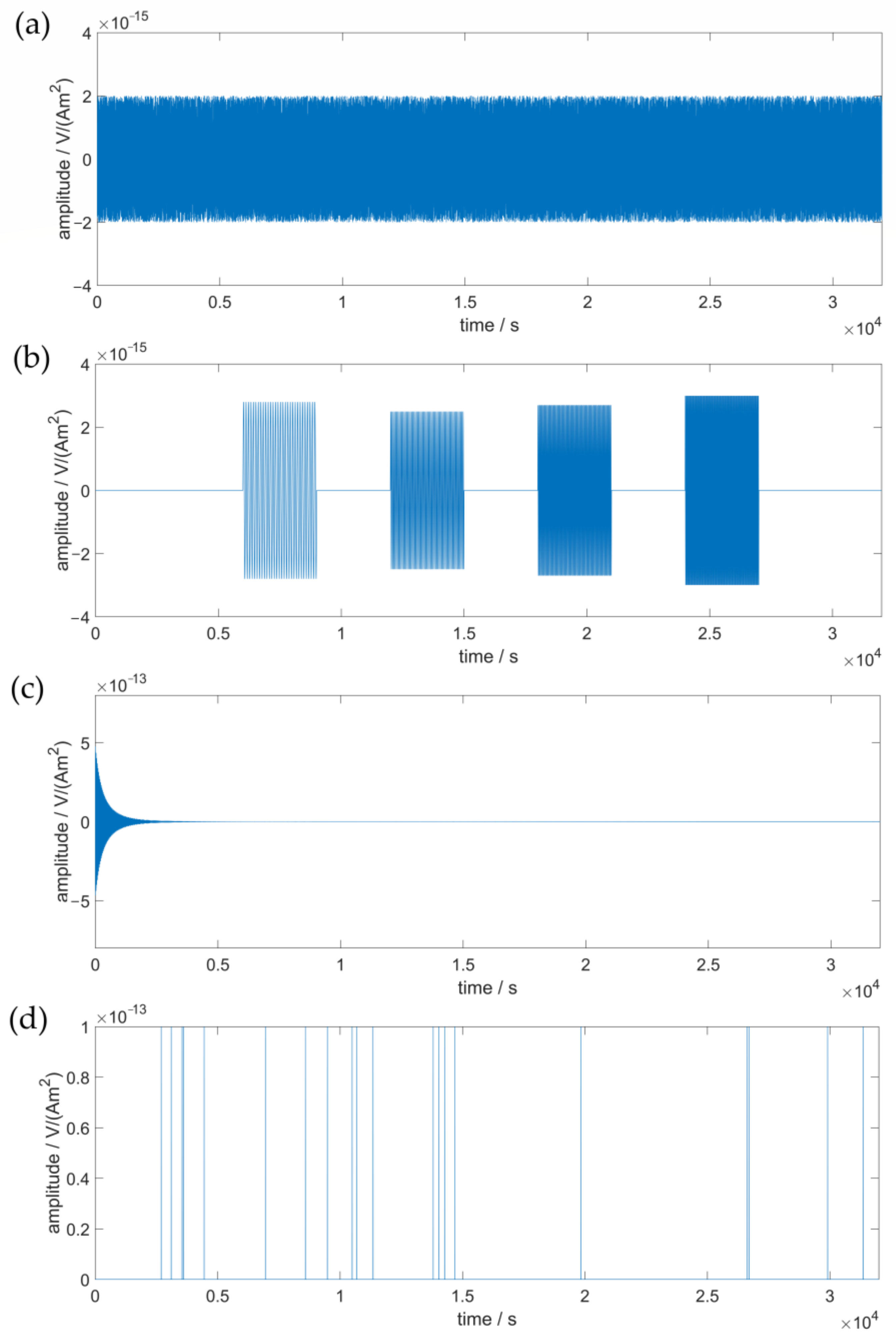
Random noise. This kind of noise is not correlated with the signal. Generally, the average magnitude of random noise decreases as the water depth increases. Considering the depth in this study, the magnitude is from 1 × 10 15   V / A m 2 to 2 × 10 15   V / A m 2 , and does not follow a Gaussian distribution [38]. This noise is shown in Figure 3a.
(2)
Sea water motion noise. This low-frequency noise originates from the seafloor currents, where voltage is induced by the motion of a conductor [39]. The noise is composed of several low-frequency sine signals (0.01 Hz, 0.02 Hz, 0.03 Hz and 0.04 Hz) with a random distribution in the recorded signal. For each sine signal, the magnitude of the noise is fixed within a range of 2 × 10 15 V / A m 2 to 3 × 10 15 V / A m 2 . This noise is shown in Figure 3b.
(3)
Internal noise. This is from the internal electrode and amplifier noise. This kind of noise is related to the instruments and varies with the magnitude of the original signal; as shown in Figure 3c, it is set as 1% of the original signal [21].
(4)
Impulse noise. Due to the complexity of the environment and the error in measurement, impulse noise can be reasonably considered as accidental disturbances. In total, 20 positive impulses are randomly distributed on the signal with a magnitude of 1 × 10 13 V / A m 2   [21]. This noise is shown in Figure 3d.

3.3. Synthetic Data

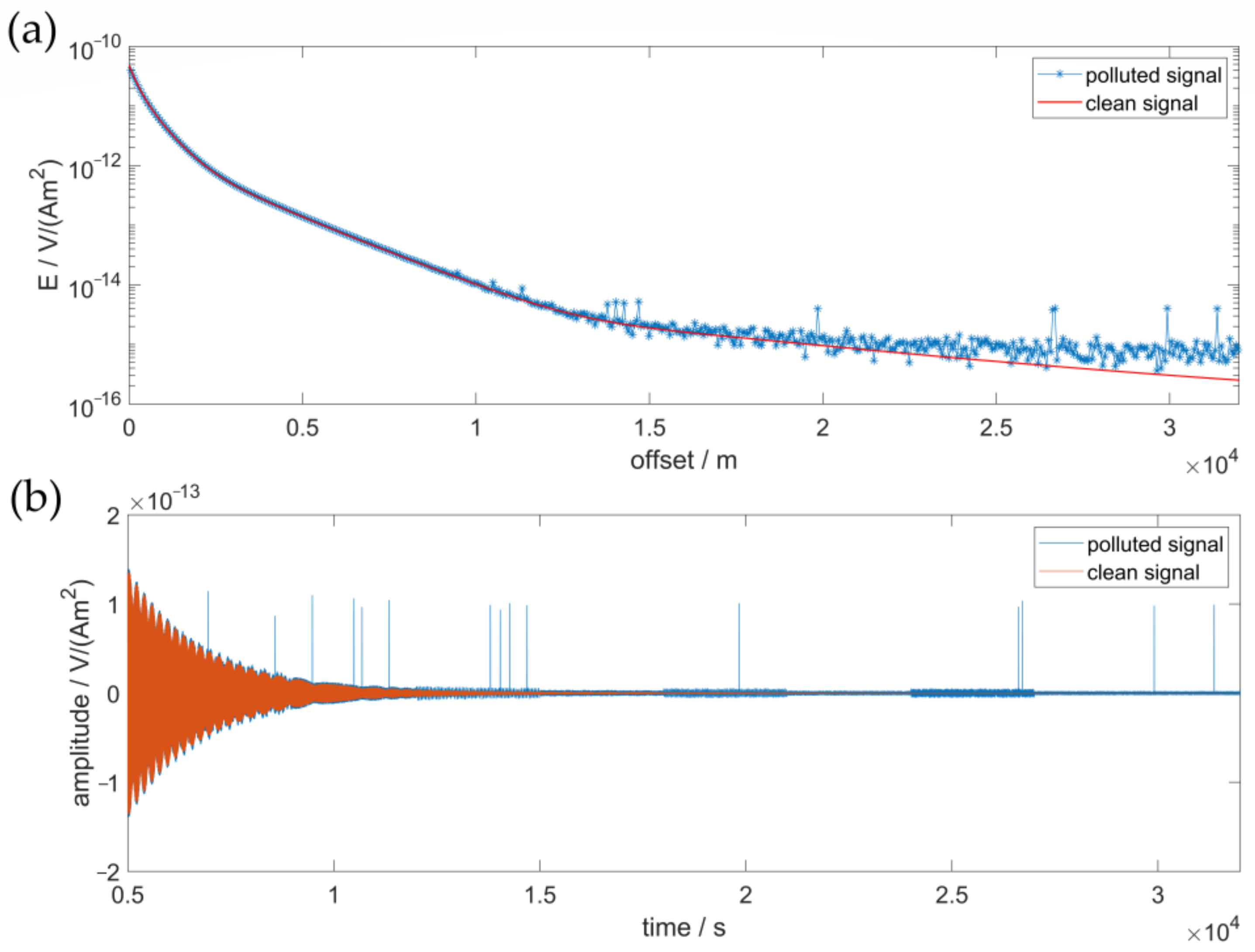
The synthetic data were acquired by adding the four types of noise to the original signal as shown in Figure 2b. The MVO plot, as shown in Figure 4a, was then obtained by solving the system of overdetermined equations, which is composed of synthetic data [40]. The length of the time window was set as 60 s. Figure 4b is the partially enlarged view of the synthetic data, and the distribution of the noise can be observed.
According to Figure 4a, the evident deviations on the polluted MOV plot appeared around 12,000 m, and the impacts became serious as the offset increased. As illustrated in Figure 4b, the polluted signal was heavily influenced by the noise since nearly the same offset and was gradually contaminated over time.

4. Denoising Experiments

4.1. VMD and Wavelet Denoising

VMD begins with the construction of the variational model and separates several intrinsic mode functions (IMFs) based on the central frequency as well as band width [13]. As a frequency domain, non-recursive decomposition method, VMD can avoid mode mixing and edge effects. Meanwhile, it has noise robustness. However, there are six parameters involved when VMD decomposes the signals, and only the appropriate combination of the parameters for each signal allows for the advantages mentioned above. In this study, the strategy for selecting the parameters was from Matlab’s Signal Processing Toolbox. After decomposition, the signal was reconstructed by adding the IMFs, and the residual was regarded as the noise [12].
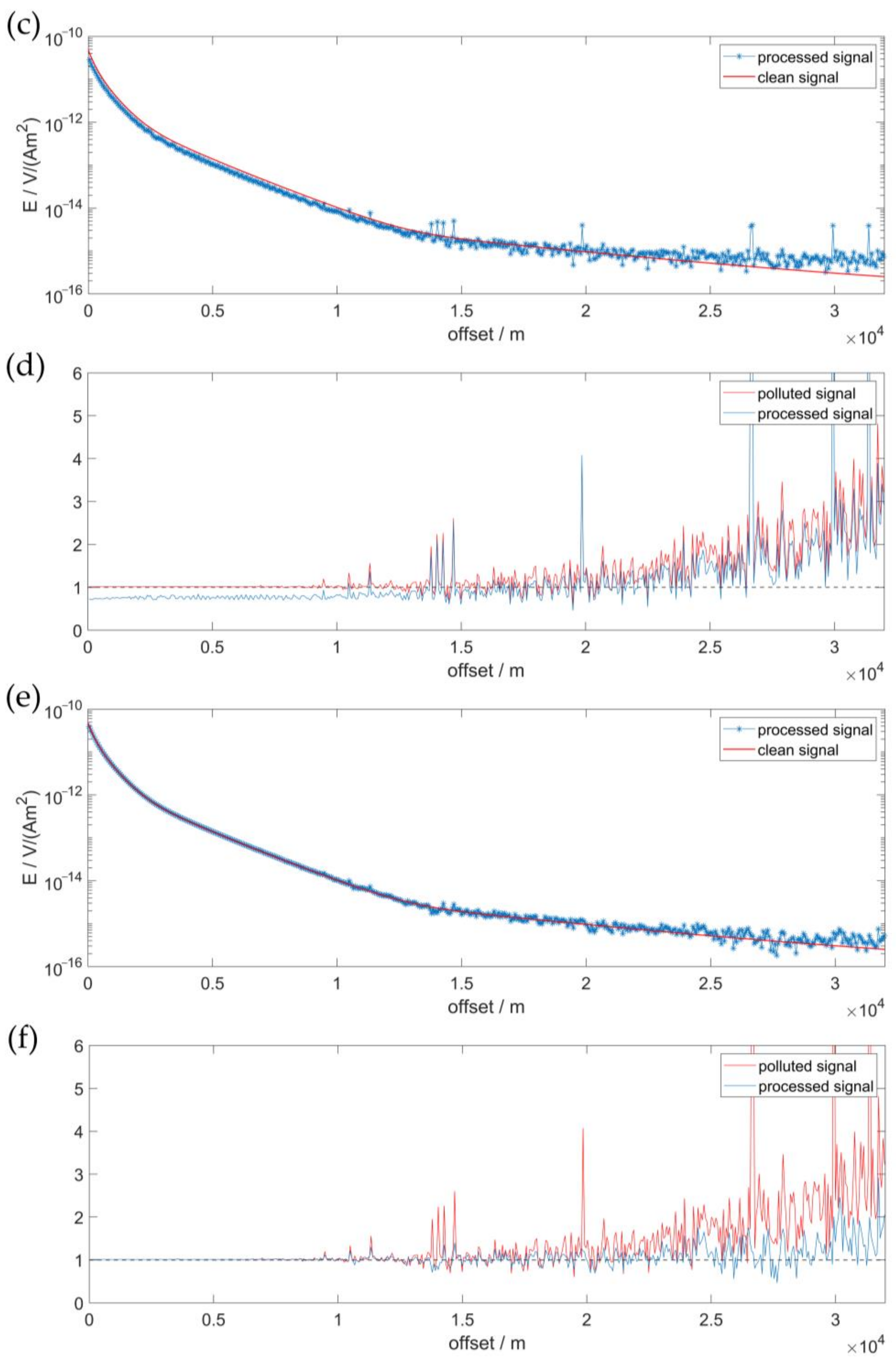
The processed data were acquired by applying VMD to the synthetic data, and the corresponding MVO plot is shown in Figure 5a. Compared with Figure 4a, only a few slight improvements appeared between 18,000 m and 22,000 m. In order to make a clear contrast, the amplitudes of the polluted MVO plot and the processed MVO plot were each normalized by that of the original MVO plot; the result is shown in Figure 5b. After 18,000 m, the blue line is below the red line, indicating that the processed MVO plot is closer to the plot in Figure 2a. However, for the spike pulses caused by impulse noise, the improvement was slight. This proved that VMD can slightly reduce the influences of various noises, except the impulse noise.
The wavelet denoising method is a widely used tool in data processing. It decomposes the signal into multiple components with different frequencies, but unlike the traditional Fourier transform, the representation of the signals in wavelet denoising is in the time-scale domain, allowing the components to be analyzed without losing temporal information. In this study, the mother wavelet was symlet4, and the synthetic data were decomposed into four levels. The wavelet denoising algorithm was minimax threshold with level-dependent soft thresholding [21].
The processed MVO plot and the corresponding normalized amplitude plot are shown in Figure 5c,d. Compared with the results of VMD, there were improvements between 15,000 m and 20,000 m in Figure 5c. In Figure 5d, the blue and red lines separate more clearly. This demonstrates that the wavelet denoising performs better on MVO plots than VMD in terms of the impacts of various noises.
However, the denoising effects of the two methods were insufficient at large offsets where the signals were completely covered by noise. Furthermore, both methods could not effectively remove the impulse noise.

4.2. SGMD Denoising

Before performing SGMD, the termination condition strategy should be discussed. Actually, the termination condition affects the number of decomposition components rather than the first few components. In addition, the principal components are located at the front of matrix transformed by diagonal averaging, which is involved in the matrix decomposition. As a result, the termination condition in the appropriate range will have little effect on the results. The termination condition in this study was set at 0.05.
After that, the effective components were selected and input into the Hampel filter. The PSD illustrates the energy distribution of a signal in the frequency domain and serves as the foundation for selection. We calculate the PSD of each decomposition component, and the component whose frequency had the largest energy that was the same as that of the transmitting signal, was picked out. Considering the time window of the previous procedures and the magnitudes of the signal, the window of the Hampel filter was also 60 s, with a standard deviation of 3.
Figure 5e,f show the processed MVO plot and the corresponding normalized amplitude plot. Compared with Figure 5a,c, there were significant improvements in the whole curve, especially at intermediate-to-long offsets. Furthermore, the impulse noise was better suppressed than with the VMD and wavelet denoising methods. In Figure 5f, the blue line clearly separates from the red and is much closer to the standard line, demonstrating that the denoising performance of this method is more complete than those of the two other methods.

4.3. Quantitative Contrast

Generally, the signal-to-noise ratio (SNR) and root-mean-square error (RMSE) are used to evaluate the data quality, which are defined as:
SNR = 10 log 10 i = 1 N x ( i ) 2 i = 1 N ( x i x ( i ) ) 2 ,
RMSE = 1 N i = 1 N ( x i x ( i ) ) 2 ,
where x(i) is the clean data and x (i) is the processed data. However, it is not appropriate to calculate the SNR and RMSE of the whole data set because the magnitudes decay rapidly with increasing offset, resulting in large variations in data quality. Here, we divided the data into 640 segments, and calculated the SNR and RMSE of each segment, which are shown in Figure 6.
As shown in Figure 6a, the black line represents the SNRs of the polluted signal, and it is clear that the hollows were primarily caused by sea water motion noise, while the spike pulses were caused by impulse noise. Random noise and internal noise were distributed throughout the signal, resulting in an overall attenuation trend of the SNRs. Compared with the VMD and wavelet denoising methods, SGMD can clearly depress various types of noise, improving data quality significantly. The denoising performance of VMD on sea water motion noise was better than that of the wavelet denoising method, but for both methods, the effects on random noise and impulse noise were insufficient.
The RMSEs corresponding to the three methods are illustrated in Figure 6b, and the noise distributions were similar to those analyzed above. The RMSEs corresponding to SGMD were much smaller than those of the two other methods, indicating that the processed data were closer to the clean data.

4.4. Occam Inversion

Another method for assessing data quality is inversion, which reflects the resistivity structure under the seafloor. Occam inversion, proposed by Key, can be divided into two phases [41]. The first phase is to find the model that best fits the observed data and the second phase is to reduce the model roughness as much as possible. MARE2D code was employed to carry out the inversion.
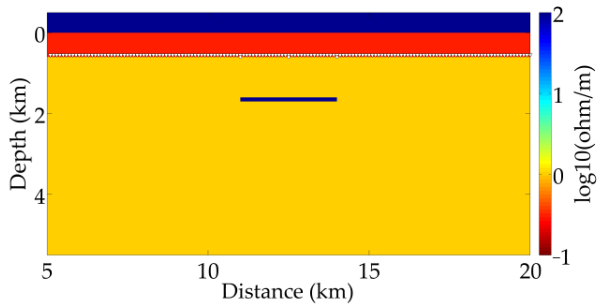
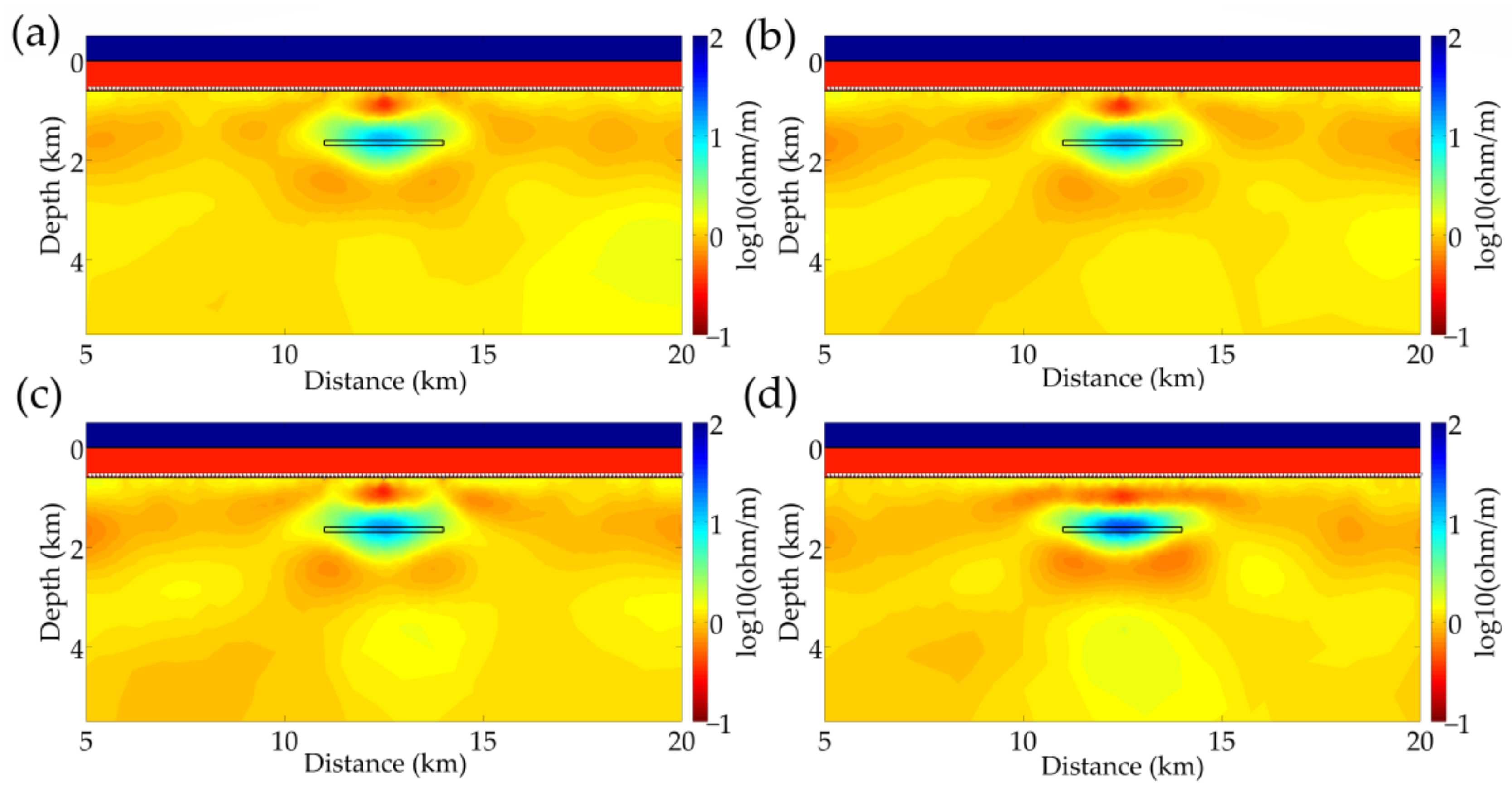
The model used in inversion is slightly different from the forward model: the length of the reservoir in the y axis was fixed at 3000 m, as shown in Figure 7. The noise model is the same as that of the forward simulation and then the polluted and processed data were transferred into E y , which was utilized as the inversion input.
Figure 8a is the inversion result of the polluted signal; although the reservoir was detected, the boundaries were unclear and the resistivity was smaller than it was in reality. Figure 8b,c illustrate the results of the VMD and wavelet denoising methods, respectively. Compared with Figure 8a, there was almost no improvement when varieties of noise exist. The result of SGMD is shown in Figure 8d, where the boundaries of resistivity anomaly were smooth and the resistivity was closer to reality, in contrast to the two other methods.

5. Conclusions

The marine CSEM signals are easily affected by various types of noise as the rapid attenuation of amplitudes. Denoising is an indispensable procedure to improve the data quality. In this study, a denoising method using SGMD was proposed to suppress a variety of noises simultaneously. Firstly, a series of single components is obtained by SGMD. Then, we calculate the PSD of each component and pick out the effective signals. Finally, they are put into the Hampel filter and used to reconstruct the processed signal.
We compared the proposed method to the VMD and wavelet denoising methods and verified its superiority in three criteria. The first criterion is the MVO plot, which is the forward response of the marine CSEM method. The MVO plot processed by SGMD was closer to the theoretical plot, especially at intermediate-to-long offsets, and the normalized amplitude plot clearly separated from the noisy result. The second is the quantitative indicator including SNR and RMSE. We plotted the SNRs and RMSEs with varying offsets, and directly showed the improvement of data quality using SGMD. The third is inversion result, which shows that the processed outline of the resistivity anomaly was smooth and the resistivity was closer to reality. All the results demonstrate that the method using SGMD has a significant and comprehensive performance in denoising when various types of noise exist.
In SGMD, the reconstruction of the phase space is the critical step before decomposition, and the combination of delay time and embedding dimension may affect denoising performance; therefore, more research on the parameters may be desired. Furthermore, we used PSD to select the effective components after decomposition, but the relationships between different components require further research.

Author Contributions

Conceptualization, Y.C. and D.G.; methodology, Y.C. and Z.G.; formal analysis, Y.C. and Z.G.; writing—original draft preparation, Y.C.; writing—review and editing, all authors; funding acquisition, Z.G. and D.G. All authors have read and agreed to the published version of the manuscript.

Funding

This research was funded by the National Natural Science Foundation of China (Grant No. 42074169), Major Project of Hunan Province Science and Technology Innovation (2020GK1021), and Open Research Fund Program of Key Laboratory of Metallogenic Prediction of Nonferrous Metals and Geological Environment Monitoring (Central South University), Ministry of Education (Grant No. 2022YSJS16).

Data Availability Statement

The data associated with this research are available and can be obtained by contacting the corresponding author.

Acknowledgments

We thank three anonymous reviewers for their constructive comments.

Conflicts of Interest

The authors declare no conflict of interest.

References

  1. Eidesmo, T.; Ellingsrud, S.; MacGregor, L.M.; Constable, S.; Sinha, M.C.; Johansen, S.E.; Kong, F.N.; Westerdahl, H. Sea bed logging (SBL), a new method for remote and direct identification of hydrocarbon filled layers in deepwater areas. First Break 2002, 20, 144–152. [Google Scholar]
  2. Ellingsrud, S.; Eidesmo, T.; Johansen, S.; Sinha, M.C.; MacGregor, L.M.; Constable, S. Remote sensing of hydrocarbon layers by seabed logging (SBL): Results from a cruise offshore Angola. Lead. Edge 2002, 21, 972–982. [Google Scholar] [CrossRef]
  3. Mittet, R.; Morten, J.P. Detection and imaging sensitivity of the marine CSEM method. Geophysics 2012, 77, E411–E425. [Google Scholar] [CrossRef] [Green Version]
  4. Christensen, N.B.; Dodds, K. 1D inversion and resolution analysis of marine CSEM data. Geophysics 2007, 72, WA27–WA38. [Google Scholar] [CrossRef] [Green Version]
  5. Constable, S. Ten years of marine CSEM for hydrocarbon exploration. Geophysics 2010, 75, A67–A75. [Google Scholar] [CrossRef] [Green Version]
  6. Key, K. Marine electromagnetic studies of seafloor resources and tectonics. Surv. Geophys. 2012, 33, 135–167. [Google Scholar] [CrossRef] [Green Version]
  7. Zhu, J.; Wang, G.; Huang, Y.; Zhang, X.; He, R.; Chen, F. A denoising method for ultrasonic testing of rubber composites based on improved symplectic geometric mode decomposition. Appl. Acoust. 2023, 209, 109428. [Google Scholar] [CrossRef]
  8. Myer, D.; Constable, S.; Key, K. Broad-band waveforms and robust processing for marine CSEM surveys. Geophys. J. Int. 2011, 184, 689–698. [Google Scholar] [CrossRef] [Green Version]
  9. Attias, E.; Weitemeyer, K.; Minshull, T.A.; Best, A.I.; Sinha, M.; Jegen-Kulcsar, M.; Holz, S.; Berndt, C. Controlled-source electromagnetic and seismic delineation of subseafloor fluid flow structures in a gas hydrate province, offshore Norway. Geophys. J. Int. 2016, 206, 1093–1110. [Google Scholar] [CrossRef] [Green Version]
  10. Schmidt, O.T.; Colonius, T. Guide to spectral proper orthogonal decomposition. Aiaa J. 2020, 58, 1023–1033. [Google Scholar] [CrossRef]
  11. Li, S.; Jiang, S.; Wang, Y.; Yu, S. A wavelet correction method for the seawater turbulence noise in marine controlled-source electectromagnetic data. Geophys. Prospect. Pet. 2016, 55, 657–663. [Google Scholar]
  12. Zhang, J. Research on Noise Suppression Technology of Marine Controlled-Source Electromagnetic Data Based on VMD; Jilin University: Changchun, China, 2021. [Google Scholar]
  13. Dragomiretskiy, K.; Zosso, D. Variational mode decomposition. IEEE Trans. Signal Process. 2013, 62, 531–544. [Google Scholar] [CrossRef]
  14. Baldazzi, G.; Solinas, G.; Del Valle, J.; Barbaro, M.; Micera, S.; Raffo, L.; Pani, D. Systematic analysis of wavelet denoising methods for neural signal processing. J. Neural Eng. 2020, 17, 066016. [Google Scholar] [CrossRef] [PubMed]
  15. Peng, Z.; Jackson, M.R.; Rongong, J.; Chu, F.; Parkin, R.M. On the energy leakage of discrete wavelet transform. Mech. Syst. Signal Process. 2009, 23, 330–343. [Google Scholar] [CrossRef] [Green Version]
  16. Xie, H.-B.; Guo, T.; Sivakumar, B.; Liew, A.W.-C.; Dokos, S. Symplectic geometry spectrum analysis of nonlinear time series. Proc. R. Soc. A Math. Phys. Eng. Sci. 2014, 470, 20140409. [Google Scholar] [CrossRef]
  17. Amundsen, L.; Løseth, L.; Mittet, R.; Ellingsrud, S.; Ursin, B. Decomposition of electromagnetic fields into upgoing and downgoing components. Geophysics 2006, 71, G211–G223. [Google Scholar] [CrossRef] [Green Version]
  18. Mittet, R.; Gabrielsen, P.T. Decomposition in upgoing and downgoing fields and inversion of marine CSEM data. Geophysics 2013, 78, E1–E17. [Google Scholar] [CrossRef] [Green Version]
  19. Wright, D. Quantifying the effect of the air/water interface in marine active source EM. J. Appl. Geophys. 2015, 118, 92–105. [Google Scholar] [CrossRef]
  20. Li, G.; Tang, F.; Li, C.; Lei, W.; Liu, Y. Improved detectivity for detecting gas hydrates using the weighted differential fields of the marine controlled-source electromagnetic data. J. Mar. Sci. Eng. 2022, 10, 161. [Google Scholar] [CrossRef]
  21. Zhang, P.; Deng, M.; Jing, J.; Chen, K. Marine controlled-source electromagnetic method data de-noising based on compressive sensing. J. Appl. Geophys. 2020, 177, 104011. [Google Scholar] [CrossRef]
  22. Zhang, P.; Pan, X.; Liu, J. Denoising Marine Controlled Source Electromagnetic Data Based on Dictionary Learning. Minerals 2022, 12, 682. [Google Scholar] [CrossRef]
  23. Pan, H.; Yang, Y.; Li, X.; Zheng, J.; Cheng, J. Symplectic geometry mode decomposition and its application to rotating machinery compound fault diagnosis. Mech. Syst. Signal Process. 2019, 114, 189–211. [Google Scholar] [CrossRef]
  24. Pan, H.; Yang, Y.; Zheng, J.; Cheng, J. A noise reduction method of symplectic singular mode decomposition based on Lagrange multiplier. Mech. Syst. Signal Process. 2019, 133, 106283. [Google Scholar] [CrossRef]
  25. Yu, B.; Cao, N.; Zhang, T. A novel signature extracting approach for inductive oil debris sensors based on symplectic geometry mode decomposition. Measurement 2021, 185, 110056. [Google Scholar] [CrossRef]
  26. Cheng, J.; Yang, Y.; Li, X.; Pan, H.; Cheng, J. An early fault diagnosis method of gear based on improved symplectic geometry mode decomposition. Measurement 2020, 151, 107140. [Google Scholar] [CrossRef]
  27. Zhang, G.; Wang, Y.; Li, X.; Tang, B.; Qin, Y. Enhanced symplectic geometry mode decomposition and its application to rotating machinery fault diagnosis under variable speed conditions. Mech. Syst. Signal Process. 2022, 170, 108841. [Google Scholar] [CrossRef]
  28. Guo, J.; Si, Z.; Xiang, J. Cycle kurtosis entropy guided symplectic geometry mode decomposition for detecting faults in rotating machinery. ISA Trans. 2023, 138, 546–561. [Google Scholar] [CrossRef]
  29. Zhan, P.; Qin, X.; Zhang, Q.; Sun, Y. Output-Only Modal Identification Based on Auto-regressive Spectrum-Guided Symplectic Geometry Mode Decomposition. J. Vib. Eng. Technol. 2023. [Google Scholar] [CrossRef]
  30. Zhang, X.; Li, C.; Wang, X.; Wu, H. A novel fault diagnosis procedure based on improved symplectic geometry mode decomposition and optimized SVM. Measurement 2021, 173, 108644. [Google Scholar] [CrossRef]
  31. Guo, J.; Si, Z.; Liu, Y.; Li, J.; Li, Y.; Xiang, J. Dynamic time warping using graph similarity guided symplectic geometry mode decomposition to detect bearing faults. Reliab. Eng. Syst. Saf. 2022, 224, 108533. [Google Scholar] [CrossRef]
  32. Liu, F.; Wang, H.; Li, W.; Zhang, F.; Zhang, L.; Jiang, M.; Sui, Q. Fault diagnosis of rolling bearing combining improved AWSGMD-CP and ACO-ELM model. Measurement 2023, 209, 112531. [Google Scholar] [CrossRef]
  33. Packard, N.H.; Crutchfield, J.P.; Farmer, J.D.; Shaw, R.S. Geometry from a time series. Phys. Rev. Lett. 1980, 45, 712. [Google Scholar] [CrossRef]
  34. Bonizzi, P.; Karel, J.M.; Meste, O.; Peeters, R.L. Singular spectrum decomposition: A new method for time series decomposition. Adv. Adapt. Data Anal. 2014, 6, 1450011. [Google Scholar] [CrossRef]
  35. Liu, H.; Shah, S.; Jiang, W. On-line outlier detection and data cleaning. Comput. Chem. Eng. 2004, 28, 1635–1647. [Google Scholar] [CrossRef]
  36. Key, K. Marine EM inversion using unstructured grids: A 2D parallel adaptive finite element algorithm. In Proceedings of the SEG Las Vegas 2012 Annual Meeting, Las Vegas, NV, USA, 4–9 November 2012; pp. 1–5. [Google Scholar]
  37. Key, K. MARE2DEM: A 2-D inversion code for controlled-source electromagnetic and magnetotelluric data. Geophys. J. Int. 2016, 207, 571–588. [Google Scholar] [CrossRef] [Green Version]
  38. Mittet, R.; Morten, J.P. The marine controlled-source electromagnetic method in shallow water. Geophysics 2013, 78, E67–E77. [Google Scholar] [CrossRef] [Green Version]
  39. Pethick, A.M. Multidimensional Computation and Visualisation for Marine Controlled Source Electromagnetic Methods; Curtin University: Perth, WA, Australia, 2013. [Google Scholar]
  40. Behrens, J.P. The Detection of Electrical Anisotropy in 35 Ma Pacific Lithosphere: Results from a Marine Controlled-Source Electromagnetic Survey and Implications for Hydration of the Upper Mantle; University of California: San Diego, CA, USA, 2005. [Google Scholar]
  41. Key, K. 1D inversion of multicomponent, multifrequency marine CSEM data: Methodology and synthetic studies for resolving thin resistive layers. Geophysics 2009, 74, F9–F20. [Google Scholar] [CrossRef]
Figure 1. The canonical reservoir model for synthetic data.
Jmse 11 01578 g001
Figure 2. The forward response and the recorded signal. (a) Forward response, and (b) recorded signal.
Jmse 11 01578 g002
Figure 3. The constructed noise: (a) random noise, (b) sea water motion noise, (c) internal noise, (d) impulse noise.
Jmse 11 01578 g003
Figure 4. The polluted response and the polluted signal. (a) Polluted response and (b) polluted signal.
Jmse 11 01578 g004
Figure 5. The results of three denoising methods. (a) MVO plot processed by VMD; (b) normalized amplitude plot of polluted and processed signals by VMD; (c) MVO plot processed by wavelet denoising; (d) normalized amplitude plot of polluted and processed signals by wavelet denoising; (e) MVO plot processed by SGMD; (f) normalized amplitude plot of polluted and processed signals by SGMD.
Jmse 11 01578 g005aJmse 11 01578 g005b
Figure 6. (a) SNRs of the processed and polluted signals, (b) RMSEs of the processed and polluted signals.
Jmse 11 01578 g006
Figure 7. A layered model with a thin and high resistivity reservoir.
Jmse 11 01578 g007
Figure 8. The inversion results of the processed and polluted signals. (a) Result of polluted signal; (b) result of signal processed by VMD; (c) result of signal processed by wavelet denoising; (d) result of signal processed by SGMD.
Jmse 11 01578 g008
Disclaimer/Publisher’s Note: The statements, opinions and data contained in all publications are solely those of the individual author(s) and contributor(s) and not of MDPI and/or the editor(s). MDPI and/or the editor(s) disclaim responsibility for any injury to people or property resulting from any ideas, methods, instructions or products referred to in the content.