Article

A Study on the Wake Evolution of a Set of RIM-Driven Thrusters

Department of Electrical, Electronic and Telecommunications Engineering and Naval Architecture (DITEN), University of Genoa, 16145 Genoa, Italy
J. Mar. Sci. Eng. 2023, 11(9), 1659; https://doi.org/10.3390/jmse11091659
Submission received: 22 July 2023 / Revised: 18 August 2023 / Accepted: 20 August 2023 / Published: 24 August 2023

Abstract

:
In the current paper, high-fidelity improved delayed detached-eddy simulations (IDDES) using the OpenFOAM library are employed to characterize the performances and the wake dynamics of RIM-driven thrusters. Despite their relatively old conception, this type of propulsors has gained attention only recently thanks to innovative manufacturing technologies and materials, which finally have made possible their practical implementation. Fostered by stringent regulations on radiated noise and emissions enforced in protected areas, they are also replacing conventional thrusters and main propulsors. By mitigating the tip vortex cavitation and, more in general, by reducing the strength of tip vortices, indeed, these propulsors may grant a reduction in the induced pressure pulses and of the radiated noise without excessively sacrificing the efficiency of the equivalent ducted propellers they replace. To provide proof of this, three different RIM-driven thrusters (one four-bladed, two six-bladed) are analyzed and compared to a reference decelerating ducted propeller delivering the same thrust at identical functioning conditions. The evolution of the trailing wakes of the propulsors, the role of the leakage vortex, and the nozzle wake destabilizing effects, are highlighted, and the superior performances of RIM-driven thrusters, in terms of less intense tip vortices, are discussed. Near-field pressure pulses, as a measure of the radiated noise, are compared, showing a reduction in the sound pressure levels of the selected RIM propulsors up to 15 dB (non-cavitating case) with respect to the reference ducted propeller.

1. Introduction

The concept of RIM-driven thrusters dates back to the work of Saunders [1] who was among the firsts to propose driving the propeller by its blade tips. Some attempts to apply this idea can be recognized in some USSR ships [2,3], but the functional implementation of this solution, as a valid replacement of usual thrusters and main propulsors, was possible only recently, thanks to innovative technologies and materials such as brushless, highly efficient, permanent magnet, electric motors. RIM-driven thrusters, in the end, are hub-less propellers inside a nozzle. They are moved by an electric motor which rotor is embedded in a “band” on the blade tips, the “RIM”, that connects and moves all the blades, while the stator is mounted inside the duct. This is the most important constructive complexity of the system that slacked its rapid application. A quite significant advancement in electric motors manufacturing and optimization was indeed needed for an hydrodynamically efficient implementation of this propulsive concept. This includes, for instance, the realization of efficient, but compact, electric motors, which are fundamental to avoid excessively large nozzles (to house the stator) that may nullify the advantages of the absence of blade tips.
Contrary to conventional ducted propellers, RIM-driven thrusters have no gap between the blade tips and the inner surface of the nozzle. This is the most important and influencing hydrodynamic characteristic of this type of propulsors. The completely sealed gap permits higher loads on the outer portion of the blade, also for highly loaded functioning conditions, and this has direct beneficial consequences on the efficiency of the propulsor. The tip leakage vortices (i.e., the vortical structures developed as a consequence of boundary layer of the duct passing into the gap between the duct itself and the blades [4,5]) are absent. Combined with the natural mitigation of the blade tip vortices due to the absence of crossflow, this contributes to a further reduction in the energy losses in the wake, with a consequent increase in the efficiency of these propulsors.
Tip vortex avoidance (in the case of the leakage vortex) and mitigation (in the case of the blade tip vortex), furthermore, sustains the reduction in the radiated noise, which is strictly related to the dynamic and strength of the vortices shed in the wake of the propeller. Less intense tip vortices obviously postpone cavitation inception. Also, their completely different interaction with the duct wake may furthermore improve the performances of RIM-driven propellers in terms of induced pressure pulses at blade harmonics and broadband. This is of particular importance since radiated noise has received increased attention in the last few years. Improved naval systems, more comfortable cruise vessels, the impact on marine wildlife, and the consequent more stringent regulations on restricted and protected areas, have promoted the adoption and the study of innovative propulsive systems. They must be capable of maintaining a high level of efficiency (due to EEDI and EEOI compliance regarding air pollution) at a very low level of radiated noise. As the propulsor is the most important source of underwater radiated noise, RIM-driven thrusters, which seem capable of increasing the cavitation-free speed without sacrificing the efficiency, represent an interesting replacement of conventional and ducted propellers.
From the design point of view, these peculiarities have promoted the development of custom design methods. From the simplest, based on a lattice of hydrofoils, to the most complex, involving multi-objective optimization, they were developed to take advantage and account for a different optimal radial distribution of load, or for the viscous interactions between the rotor and the nozzle. In the context of potential-based and viscous/inviscid iterative methods, Sparemberg [6,7] and Mishkevic [8] used modified lifting line approaches to derive the optimal distribution of circulation for blades operating in RIM mode. Kinnas et al. [9], similarly, made use of a lifting surface design code, coupled with RANSE and BEM, to characterize a four-bladed RIM operating inside a tunnel, while Yakovlev [3] used equivalent 2D calculations to design a propulsor for bollard pull functioning. More flexible design methods, employing RANSE calculations for an accurate characterization of the interactions among the components of the propulsive system, were proposed as well. Zhai et al. [10] investigated the design of the duct of a RIM-driven thruster by using a combination of RANSE data and surrogate models useful for a computationally efficient optimization-based design. A similar use of surrogate models was proposed in [11] for the design of the most efficient blades of a RIM propulsor, while Gaggero [12] proposed a SBDO framework for the design of RIM-driven thrusters simultaneously accounting for efficiency and cavitation.
Most of the numerical activities, available in the literature, on this type of propulsor, however, were devoted to analysis rather than to design purposes. Dubas et al. [13] compared frozen rotor and unsteady calculations for a computationally efficient workflow. Song et al. [14] analyzed geometries with and without the hub, while Cao et al. [15] discussed the role of the blade shape on the overall performances of the propulsor. The influence of the number of blades, in addition to being a result of optimization activities [12], was investigated in [16]. Lin et al. [17] studied the flow, the so-called “RIM effect”, in the annulus between stator and rotor, and its influence, in terms of parasitic torque, on the global performance of the system. They also investigated the role of the annulus shape on the overall propulsive efficiency. In this respect, these analyses were an update of the simplified calculations of [8,13,15] used to correct the prediction of RIM performances when the explicit simulation of these very localized features is prohibitively expensive.
In any case, with the partial exception of Cao et al. [15] and Lin et al. [17], very few studies have been proposed on the evolution of the vortical trailing wake of RIM-driven thrusters, so important from the point of view of radiated noise. Cao et al. [15] correlated some characteristics of the trailing wake of the propellers with their blade loading distributions. They showed, for the cases under investigation, the occurrence of merging of root vortices and the sudden appearance of more intense tip vortices far in the wake. Lin et al. [17] visualized the vortical structures shed by RIM-driven thrusters. As in the calculations of [15], however, the spatial discretization as well as the employed numerical schemes were not adequate for accurate prediction of these features since the focus of their study was not explicitly on the wake dynamics. Some characteristics of the vortical wakes of RIM-driven thrusters were evidenced in the case of the optimal geometries designed in [12], but only RANSE calculations and simplified steady cases using Moving Reference Frames were employed for those analyses. None of the theoretical [18,19], experimental [20,21], or numerical studies [22,23,24,25,26,27,28,29,30,31] available for conventional and tip-loaded propellers, as well as for ducted propulsors and pumpjets, were repeated for RIM-driven thrusters with the same systematic approach.
In the light of this, the goal of the current study is to investigate the trailing wake and its destabilization in the case of three RIM-driven thrusters. Specifically, one four-bladed and two six-bladed configurations [12], designed for delivering the same thrust at identical advance coefficient and cavitation index, are considered and compared to a ducted propeller that provides the reference performances. The interaction of tip vortices with the nozzle shear layer, and the mechanism of wake destabilization, is discussed together with the induced pressure pulses in a non-cavitating regime, which represent a quantitative measure of the interactions occurring among the vortical structures. To this aim, improved delayed detached-eddy simulations (IDDES) using the Spalart–Allmaras turbulence model [32] are employed. Results are computed using the open source OpenFOAM library [33] on sufficiently fine grids that allow for the characterization of the trailed vortical structures also relatively far from the propeller trailing edge. The outcomes are discussed in the light of similar analyses, available in the literature, for ducted propellers and pumpjets, which are the propulsive solutions most close to RIM-driven thrusters. The proposed analyses show, for the particular geometries under investigation, some substantial differences compared to the reference propulsor. They are ascribable to the different nature of the flow at blade tip. An appreciable reduction in the predicted noise levels in the near field is predicted as well, confirming the superior characteristics of this type of propulsors from the radiated noise point of view.

2. Test Case

Figure 1 shows the geometries considered in the current study. They were obtained through a design by optimization having as contrasting objectives the maximization of the propulsive efficiency and the minimization of (the risk of) cavitation of a reference ducted propeller developed in the framework of the EU-funded project BESST (Breakthrough in European Ship and Shipbuilding Technologies, European Community’s Seventh Framework Programme FP7/2007-2013). The reference geometry is that of a four-bladed, controllable pitch propeller (model scale diameter of 0.23 m) working inside a decelerating nozzle and having an expanded area ratio of 0.725 and a pitch over diameter ratio of 1.354 at 0.7 r/R. Details of the geometry can be found in [5]. Its main characteristics are summarized in Table 1.
For this reference propulsor, the decelerating nozzle was preferred because the focus of the application was on reduction in the noise footprint of the naval unit (at the cost of the additional drag of the nozzle), achieved by postponing the cavitation inception through the increase in static pressure inside the nozzle. The design point of the propulsor is for a relatively high advance coefficient (J > 1). Bollard pull performances, which are crucial for more usual accelerating duct configurations, are only a consequence of the design and they were not directly monitored throughout the optimization. Despite the ducted nature of the propeller, but to comply with the need of postponing the cavitation inception of a propulsor operating at a particularly low cavitation index, the blade is characterized by a significant unloading at the tip. Unloading is achieved by a very small local value of chord and by a significant reduction in the pitch, with the aim of mitigating the occurrence of the leakage vortex in the gap between the blade and the nozzle. Indeed, the experimental observations and calculations of [5,34] put in evidence the cavitation phenomena affecting this propeller at several functioning conditions. The leakage vortex, in the form of a continuously detached structure from the leading edge to the trailing edge of the blade at the tip, and travelling downstream with a significantly reduced pitch compared to that of the trailing wake of the blade, emerged as the most relevant side effect of the propulsor. At the design functioning, this vortex was observed experimentally to be the only flow structure subjected to cavitation, with negative consequences on the acoustic performances of the propeller and on the propulsive efficiency, already sacrificed by the decelerating nature of the duct.
The RIM-driven thrusters analyzed in current work were successfully designed in [12] to mitigate exactly the tip vortex cavitation observed in the case of the ducted propeller. They all adopt the same decelerating nozzle of the reference propulsor, but radial distributions of pitch, chord, and camber were customized to exploit the absence of the gap at the tip and, given the parasitic torque of the RIM, to provide the maximum possible efficiency at reduced cavitation inception indexes. The design process, entirely based on RANSE analyses, addressed from three- to six-bladed geometries which were all designed by analyzing the performances of 3600 geometries per number of blades configuration, iteratively obtained by a genetic algorithm through the modification of eighteen design parameters. Geometric features were altered by using usual B-Spline-based curve descriptions of the corresponding radial distributions, while cavitation was monitored in a simplified way through the minimum pressure coefficient on several representative portions of the blade. The selection criteria were based primarily on cavitation avoidance: the overall best geometry, regardless of the number of blades, was the one realizing simultaneously the largest margin against any kind of cavitation inception (suction, but also pressure side, leading edge as well as midchord). Secondarily, among the geometries satisfying cavitation-free conditions, those providing the highest efficiency were additionally selected. Geometries of current analyses were identified among these reduced sets of optimal configurations, focusing on four-bladed propellers (as the reference ducted) and six-bladed configurations (those granting the best performance in terms of cavitation avoidance). A certain variety of the geometrical characteristics of the propulsors was preferred to correlate these differences to the features of the vortical wakes.
For the four-bladed RIM-driven thrusters, z4–1153 is the geometry with the highest efficiency (comparable to that of the reference propulsor). The pitch and the camber, as expected, have their maximum at the tip [12]. The two six-bladed RIM-driven thrusters were selected since they have completely different geometries, reflected in different performances for what concerns the preliminary tip vortex evolution observed in those calculations. Both significantly postpone the cavitation inception. Z6–1440 has the overall best performance on the suction side but, despite very high values of pitch and camber at the tip, it has an efficiency slightly lower than z6–4097 and the ducted propeller. Pitch at the tip is extremely unloaded for z6–4097, which indeed shows the shortest and less intense vortices. The higher values of pitch at midspan, needed to provide the required thrust, determine a slightly higher risk of leading-edge cavitation, in any case conservative if compared to the reference ducted propulsor.

3. Computational Grid and Details of the Numerical Models

The analyses of the vortical structures from the propulsor blades and nozzle were realized using the improved delayed detached-eddy simulation (IDDES) turbulence model proposed by Spalart and Allmaras [32]. Large eddy simulations (LES) would have represented an even more accurate model to study the development and the interactions between the shear layer of the nozzle and the vortical structures shed by the propulsor, but the excessive computational cost associated to this type of analysis suggested the use of hybrid models like detached eddy simulation (DES). DES are zone-based approaches, since by the use of a wall distance-based threshold, the computational domain is treated selectively in a RANSE-like or in a LES-like manner. This is useful to combine the most favorable aspects of RANSE (light grid resolution for boundary layer calculations) with those of LES (time-dependent, three-dimensional large eddy resolution in the far-field), without the burden of the (millions of) isotropic cells in the boundary layer to solve for small eddies at wall.
Among the alternatives of detached-eddy models (detached, DES, delayed detached, DDES, and improved delayed detached-eddy, IDDES), that applied in current calculations is the IDDES inspired by the original RANSE Spalart–Allmaras one equation turbulence model [32]. The turbulence model initially proposed by Spalart and Allmaras handles the turbulent stresses by solving a convective equation (Equation (1)) for the modified turbulence viscosity υ ^ :
υ ^ t + u j υ ^ x j = C b 1 1 f t 2 S ^ υ ^ c w 1 f w c b 1 κ 2 f t 2 υ ^ d 2 + 1 σ x j υ + υ ^ υ ^ x j + c b 2 υ ^ x i υ ^ x i
The turbulent eddy viscosity μ t , necessary for the calculation of the turbulent stresses through the Boussinesq linear assumption, in turn depends on the modified turbulence viscosity by:
μ t = ρ υ ^ f v 1
where ρ is the fluid density; υ the molecular kinematic viscosity; f v 1 = χ 3 / χ 3 + c v 1 3 ; c v 1 a constant equal to 7.1; and χ = υ ^ / υ . The turbulent Prandtl number σ influences the diffusion term, as for any turbulence models. The magnitude of the mean vorticity, accounted in S ^ , drives instead the production term of the model while the destruction term depends on the proximity to the nearest wall (from the field point) through the distance d . The f w function, controlling the rate of decay of the destruction term itself, is used for tuning purposes and to correct the underestimation of the skin friction typical of this turbulence model. More details of the model and of its constants are given in [32], while the documentation of the OpenFOAM library [33] provides specific information on its numerical implementation in the solver.
The zonal RANSE/LES approach, that transforms this turbulence model initially developed for RANSE into a DES, is easily realized through a modification of the wall distance d that modulates the destruction term of the turbulence viscosity. The new length scale d ˜ [35] is defined as:
d ˜ = m i n Ψ C D E S Δ , d
where Ψ is the low-Reynolds number correction function; Δ a measure of the grid spacing (the largest distance between the cell center under consideration and the cell centers of the neighboring cells); and C D E S a calibration constant.
Among the side effects of DES methods, mostly associated with the pure grid-based filtering of the models, the grid-induced separation and the log-layer mismatch are probably the most relevant ones. Over the years, they were addressed, respectively, by delayed detached-eddy simulations (DDES) and improved delayed detached-eddy simulations (IDDES) models.
“Modeled Stress Depletion” is the cause of the grid-induced separation. A premature switching of the model to LES, due to an incorrect (excessively large) stream-wise spacing of the grid, determines too weakly resolved stresses that promote an unphysical behavior. The modification introduced in DDES to comply with this issue consists of the adoption of a new length-scale distance (Equation (4)). Thanks to the use of a “delay function” f d , the new formulation tries to detect the boundary layer to locally force the RANSE behavior of the hybrid model even if the grid spacing is smaller than the boundary layer thickness. Contrary to the original DES formulation, in DDES the dissipation length scale also depends on the local eddy-viscosity (through f d ) and not only on the grid spacing. RANSE mode is activated when the function f d is 0, while LES is applied when the value is 1:
d ˜ = d f d m a x 0 , d Ψ C D E S Δ
The IDDES model [36], currently adopted, also addresses the log-layer mismatch. This is achieved by the adoption of a so-called “elevating” function that has the role of including, also through new formulations of the model constants, wall-modeled LES capabilities in the model to realize a more robust bridging between wall-resolved and wall-modeled approaches when the grids have incorrect spacing.
In relation to the spatial discretization, the computational domain adopted for the proposed calculations consists of a cylindrical region extending 2D upstream of the propeller plane, 6.5D downstream, and 4.5D in radial direction to prevent blockage phenomena. Uniform axial inflow at the inlet and fully developed flow at the outlet and on the lateral cylindrical boundary are assumed. On these latter boundaries, pressure is fixed. No-slip boundary conditions are enforced on propeller blades, hub, shaft, and nozzle while rotation is achieved through sliding interfaces that match the inner, rotating, with the external, fixed, portions of the domain. Boundary conditions are listed in Table 2. Table 3 describes the numerical schemes adopted for the simulations and the corresponding OpenFOAM naming.
The discretization of the computational domain is realized by hexa-dominant cells. A snapshot of the internal grid (RIM-driven case) of the reference mesh is given in Figure 2c. To better capture the flow features in the wake of the propulsors, the average cell size is 0.7% D up to a distance 4.0D aft of the propeller plane. An identical averaged cell dimension is used to discretize the blades. Locally, in correspondence with highly curved surfaces (blades’ leading edge, but also trailing edge), this dimension is five times smaller. Zonal refinements at the tip, extending up to 1.0D downstream of the propeller plane, have a cell size halved if compared to that on blade surfaces (0.35% of D). The near-wall resolution is of about three wall-units (design functioning) and it is achieved by fifteen prism layers on wall boundaries arranged with a moderate stretching factor of 1.2. This spatial discretization layout counts about 44 million cells for the RIM-driven configurations. For the reference ducted propeller solely, a few additional refinements were necessary, in particular to deal with the gap at the tip of the blades. Locally, the cell size was reduced to 0.08% of the propeller diameter with an increase in the total number of cells that reached 66.5 million of elements. Time discretization is obtained by a time step equivalent to 0.5 deg. of propeller rotation per step. A total of 14 propeller revolutions were solved, corresponding to at least 1.5 flow-through times.
Based on the topology of the reference grid, two additional meshes (only coarser, due to the computational effort for the type of calculations) have been derived from the reference. The cell size is uniformly scaled, except for the first prism layer cell height at wall, by a factor of about 1.25 (1.27 from reference to medium, 1.18 from medium to coarse), then is suitable for a verification study using the Richardson extrapolation. Results of the analysis are given in Table 4, while snapshots of the vorticity shed in the wake at different grid refinements are presented in Figure 3. The convergence trend is rather good. The extrapolated value for the thrust coefficient is about 97% of the reference value, with a Grid Convergence Index of 2.7% (estimated apparent order of convergence of 0.85). Torque behaves slightly better, since the extrapolated value is 104.4%, with a relative error associated with the reference grid of only 0.18% and a GCI of 0.22%.
Discussing the convergence trend in terms of wake features is prohibitive due to the unsteady and chaotic nature of the phenomena under investigation. From a mere qualitative point of view, in any case, very similar phenomena of vortex/duct shear layer interactions and trailing wake bending and roll-up, which are extensively discussed in the next sections, can be observed on the three grid densities under investigation of Figure 3. In the absence of an even finer grid arrangement, and based on these results, the reference mesh of about 44 million cells was considered suitable for all the subsequent analyses.

4. Results and Discussion

4.1. Propeller Performance

Before analyzing the propulsors in terms of characteristics and dynamics of vortical wakes and tip vortices, more traditional propeller performances (namely thrust, torque, and efficiency) were considered. Indeed, the RIM-driven thrusters were developed through an SBDO method [12] with the aim of postponing as much as possible the risk of cavitation at the maximum possible propulsive efficiency. Current IDDES analyses (but also RANSE on the same refined computational grids) can provide further insights, using high-fidelity calculations, into the reliability of the design process and the performances of these propulsors. Compared to the original calculations of the optimization process ( S S T   k ω turbulence model, steady, using a moving reference frame on a mesh of about 1 million cells per blade passage), the propeller performances predicted using current grids and turbulence model show some differences, especially when IDDES is considered. For design purposes, indeed, the propulsors’ delivered thrust was constrained to be ±2% of that computed for the reference ducted propeller (using a comparable grid arrangement) and all the optimal geometries were selected accordingly. Calculations with the finer grid arrangement selected for current investigations only partially satisfy this constraint. By looking at the predicted performances using the RANSE formulation of the Spalart–Allmaras turbulence model (Table 5), the differences are negligible. The total delivered thrust is almost within the prescribed threshold and the torque shows the overestimation already observed during the design-by-optimization process. The reference ducted propeller, the only one that can be compared to the available experimental measurements, is very similarly predicted in terms of thrust. The resulting efficiency due to the overestimation of torque is slightly lower but the relative merits of each optimized RIM configuration are confirmed. The four-bladed RIM-driven thruster (z4–1153) has the highest efficiency. Z6–4097 and z6–1440 confirm their performances, with z6–1440 being the worst of the three.
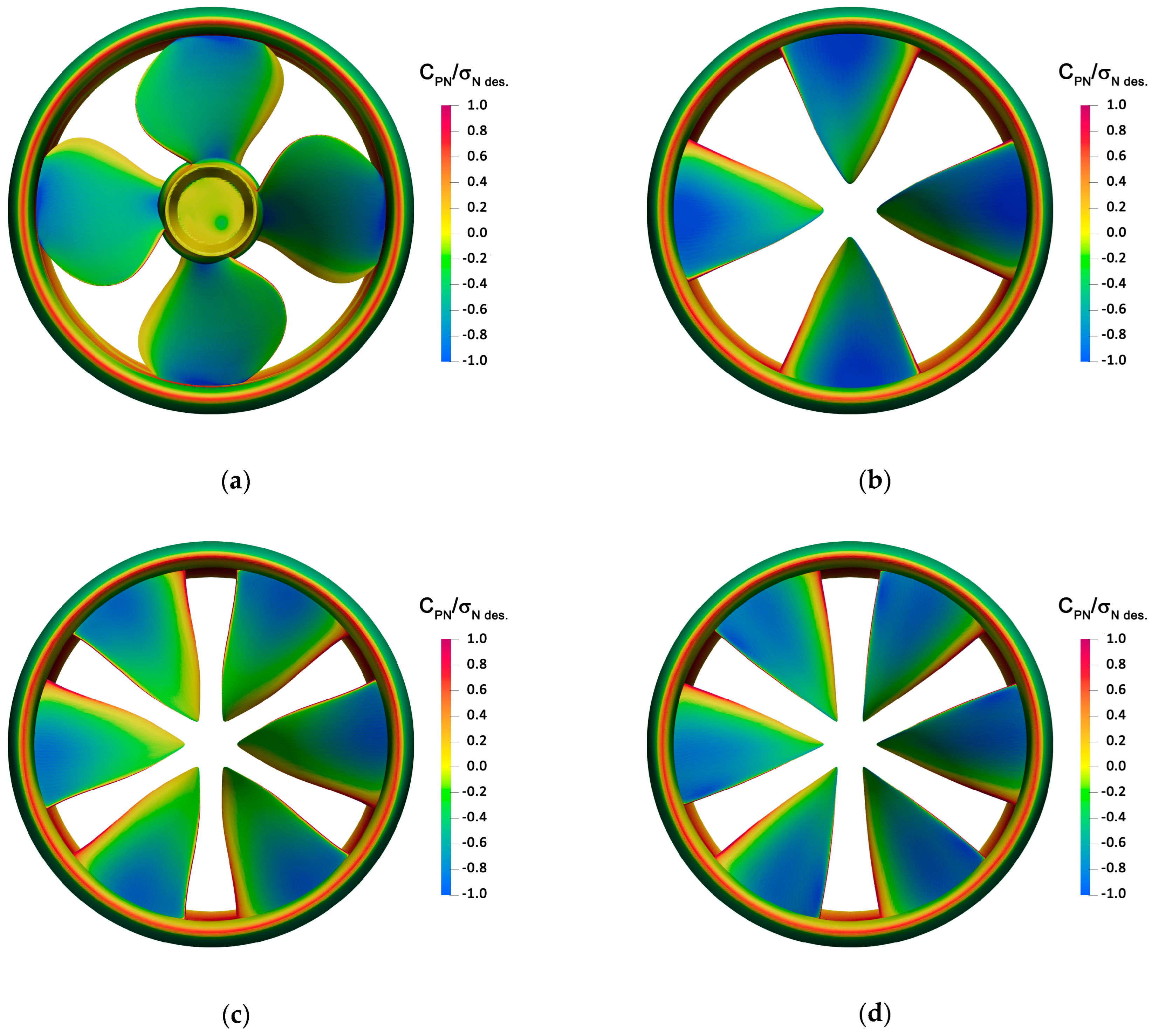
IDDES’ simulations provide slightly worse results. The ranking of geometries in terms of efficiency is confirmed (z4–1153 with the highest efficiency, then z6–4097, and z6–1440) but the delivered thrust is sensibly lower. Compared to the reference, IDDES analyses suffer an averaged underestimation of 5% that also affects the original ducted propeller. By looking in more detail at the reasons for these discrepancies, it can be seen that when IDDES is employed, the differences are almost entirely ascribable to a different prediction of the blade performances, which result is always underestimated compared to the equivalent RANSE analyses, while no substantial differences are observable in terms of resistance provided by the nozzle and the RIM. Pressure distributions, shown in Figure 4, are in any case consistent with the outcomes of the optimization process. Cavitation inception (CPNNdesign < −1) is observable at the leading edge and in correspondence of the leakage vortex in the case of the reference-ducted propeller. Among the RIM-driven thrusters, z4–1153 has the minimum of pressure at midchord, while z6–1440 and z6–4097 show higher margins against cavitation at the tip of the blade. Their risk of inception is moved towards the leading edge in accordance with the analyses and the adopted selection criteria accepted during the design process [12].

4.2. Wake Evolution and Instability

Conventional propellers have been extensively studied from both the theoretical, the experimental, and the numerical point of view. Instead, for non-conventional geometries, there are still few papers addressing the mechanism of wake instabilities when the usual tip vortex of propeller blades interacts, for instance, with the nozzle, the stator blades, or other devices. In the case of RIM-driven thrusters, these analyses are almost non-existent. Specific destabilization mechanisms have been highlighted recently in the case of ducted propellers through dedicated numerical calculations [28] and also pumpjets underwent detailed numerical analyses aimed at characterizing the rotor/stator (or vice versa) wakes’ interaction [26,27,31]. These propulsors are rather similar to RIM-driven, at least for the presence and the influence of the nozzle and its shear layer, but their leakage tip vortex plays a completely different role, suggesting the relevance of accurate investigations dedicated to “tip-less” propulsors. This is the aim of the calculations proposed in the current paper. By considering propulsors designed exactly for the same functioning conditions, they may provide a fair comparison (and discussion on the role of some blade characteristics) between the reference ducted propeller and a series of RIM-driven thrusters having, with the exception of the number of blades, slightly different geometrical features. All the designs, for instance, being the result of an optimization-based process, represent “best-balanced” configurations with respect to the contrasting objectives (and, in turn, geometrical features) of efficiency and cavitation. Consequently, solutions with excessive nozzle drag (due to its decelerating nature) compensated by a higher blade thrust are naturally discarded, and this action automatically prevents the analyses and the comparisons of geometries with a serious risk of duct boundary layer separation which hasten wake instability mechanisms [26].
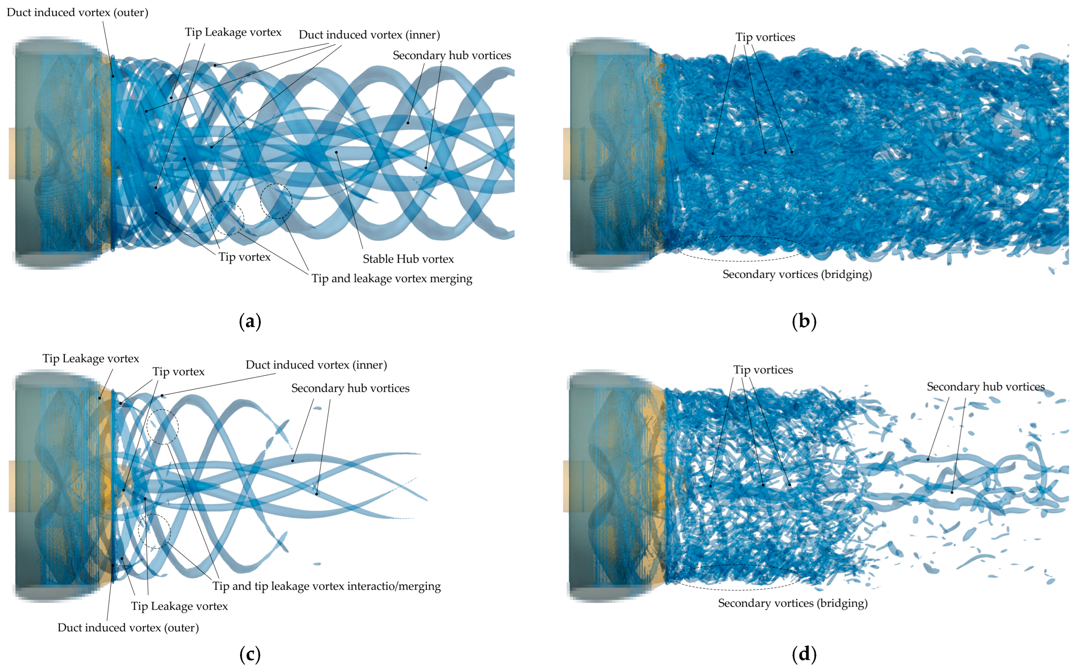
To sustain the discussion, the wake and tip vortices shed by the reference ducted propeller are investigated first. They are shown in Figure 5 (instantaneous isosurface of the second invariant of the velocity tensor, taken after 14 propeller revolutions) and in Figure 6 (magnitude of the vorticity on the longitudinal plane, same time step). In addition to the IDDES calculations, RANSE analyses (and this is also performed for all the RIM-driven thrusters) are also included. The abundance of vortical structures emanating from the nozzle, the secondary vortices, bridging tip vortices, and the duct shear layer, prevents any easy interpretation of the most relevant and coherent structures shed in the wake. RANSE analyses, thanks to their averaging nature, simplify the visualization of averaged vortical structures that are then discussed and evidenced in the corresponding IDDES calculations. To the same aim, two different thresholds on Q are employed as a way of distinguishing the strength of the vortical structures shed by the propulsors.
As already observed in similar calculations [31], the tip leakage vortex is easily recognizable inside the nozzle. As discussed in the description of the reference ducted propeller characteristics and geometry, tip leakage vortices are the most relevant vortical structures shed by the blade tips. They are placed side by side to secondary helical vortical structures, the “duct induced vortices” shown in [26], which instead are developed in the blade passage between the blades and detaches from the trailing edge of the nozzle. These structures, already evidenced by RANSE [37] are visible also on the outer surface of the nozzle in correspondence of the trailing edge. Compared to the analyses of Qin [27], the current propeller is working at the design point. The nozzle, then, is aligned to the inflow. This minimizes the risk of separation and permits only the presence of very weak secondary vortices confined to the trailing edge of the outer nozzle surface. The helical pitch of the blade trailing wake, easily observable in the propeller stream tube, is significantly higher than that of the leakage vortex, which has instead a reduced pitch due to the influence of the internal boundary layer of the duct. The “traditional” vortex from the blade tip, as well, has a much higher pitch, and this determines interactions between the tip vortex of one blade and the secondary and leakage vortices of the previous one.
By looking at the IDDES calculations, however, the triggering mechanism of the trailing wake instability seems very different to what can be concluded based only on current RANSE analyses and on the results of [37]. Mutual inductance instability mode [18], or “leapfrogging”, is the usual trigger of wake destabilization, especially for conventional propellers [21]. It takes place through the interaction of adjacent vortical helical filaments, and its occurrence is a function of the distance between vortices, then of the advance coefficient and blade loading. A similar interaction, even if influenced by the presence of the nozzle shear layer, is evidenced in the RANSE analyses as well as in the calculation by [37]. Thicker vortical structures are observable at a certain distance from the duct, where the tip leakage vortex merges with the secondary duct-induced vortices. Switching to IDDES, instead, highlights a much more complex interaction that in the end nullifies the (short) stable region of the propulsor wake observed with RANSE calculations. The tip vortices (leakage and duct induced) are wrapped by very intense secondary vortical structures that, as observed by Gong et al. [28], promote the mutual induction that appears as a short-wave instability, i.e., a small sinusoidal displacement of each filament, just aft of the nozzle trailing edge [18,38]. These secondary vortical structures, bridging subsequent helical vortices, mainly rise from the interaction of the duct-induced vortices, the tip leakage vortex of the blade, and the shear layer of the duct [26,39,40] even if they have also been observed in the case of conventional propellers but in very highly loaded conditions [22]. The rolling up and wrapping process between tip leakage vortices and secondary duct–induced vortices promote these secondary structures that realize the “tip-duct mutual inductance instability” described in [26]. Disturbed by the presence of helical vortices (tip or tip leakage from the blades), the shear layer formed on the nozzle surface and shed in the wake is distorted and reorganized into the secondary vortices between the tip and the leakage vortices. This is the turbulence kinetic energy disturbance of the tip vortex described in [26] that fosters the destabilization. With IDDES, anyway, it is difficult to easily distinguish between tip leakage, blade tip vortex and secondary duct-induced vortices. Only few coherent structures hidden by an almost continuous “ring sheet” of secondary vortices are recognizable. Their pitch, compared to that observed in case of RANSE calculations, is slightly decreased, probably as a consequence of a more intense mutual induction with the stronger secondary structures.
The spiral-to-spiral and the tip-duct mutual inductance are not the sole interactions observable in the wake of the reference ducted propeller since the IDDES analyses highlight also a certain trailing wake/tip vortex interaction. The roll-up process of the blade trailing wake, described in [23], is observable from the vorticity distribution in the X-Z plane of Figure 6. Based on their radial (root or tip) position, the opposite strength of tip and root trailing vortices induces a tangential and radial deformation of the trailing vortical wake. This turns into an “approaching” of the outer portion of the trialing wake towards the tip leakage and the duct-induced vortices, promoting an additional interaction and a further destabilization action. The hub vortex, which seems to have a stable nature when analyzed using RANSE (a single hub vortex surrounded by four secondary root vortices), loses its stability when the phenomenon is addressed using IDDES. As a consequence of the interaction with the blade root vortices not yet merged, because of the rolling up/bending process of the blade trialing wake occurring also in correspondence of the inner blade sections, the hub vortex undergoes a spiraling effect that determines the very unstable behavior observed in Figure 5d and Figure 6b.
The phenomena that can be evidenced in the wake of RIM-driven thrusters (Figure 7, Figure 8, Figure 9, Figure 10, Figure 11 and Figure 12) are rather similar but with the obvious absence of the leakage vortices. This contributes to an even earlier destabilization of the wake (i.e., absence of coherent helical vortical structures at the blades tip) since the weaker tip vortices are easily and rapidly incorporated into the duct-induced and secondary structures. The absence of the hub, moreover, contributes to a rather different dynamics of the free root vortices, which are not necessarily stronger than those of a propeller with the hub (please note that also for RIM-driven thrusters the nomenclature of conventional propeller is assumed, i.e., root correspond to the innermost section of the blade).
In the case of z4–1153, RANSE analyses put in evidence the presence of “averaged” secondary vortices similar to those observed for the reference ducted propeller. These secondary vortices are developed in the blade passages and have a much higher strength than that sort of blade tip vortices (more similar to a locally more intense trailing wake rather than a truly tip vortex from crossflow, as per Figure 8) leaving the nozzle trailing edge with a pitch sensibly higher than the secondary structures. These latter prevail in the wake (as from the comparison of the different thresholds of Q) and explain the wrapping secondary structures observable in the corresponding IDDES analyses. The shear layer of the nozzle is continuously influenced by the tip vortices of the blades. They rearrange it from the “ring sheet” of vortices (typical of a nozzle alone) into the several helical vortices (at very reduced pitch) of the duct-induced structures, continuously connected by the shear layer itself through the bridging secondary vortices. The absence of a hub, and the geometry of these RIM-driven blades, promote the formation of intense root vortices, stronger than the equivalent root structures of the reference ducted propeller. Among the RIM-driven thrusters under investigation, this is the only case of very strong root vortices because of the value of pitch at root (about 1.24), which is the highest among the considered geometries. The roll-up process [23] is consequently more evident in the inner portion of the wake rather that at the tip (Figure 8), and also a certain fragmentation of the vortical structures, attracted towards the inner and the outer tip vortices, is present. Despite the formation of inner vortices from the trailing wake, the trailing wake/previous blade root vortex interaction is not sufficient to promote the destabilization of the stronger root vortices, that maintain their stable nature up to a distance of 2.0D from the propeller before vanishing as a consequence of the now insufficiently fine grid arrangement.
Six-bladed RIM-driven thrusters naturally reduce the vortex-to-vortex distance but, contrary to what happens in the case of open propellers due to easier mutual inductance and anticipated long-wave instabilities, this has no substantial influence on the destabilization process. Also, for these geometries, the role of the shear layer is indeed dominant for the instauration of the tip/duct mutual inductance instability. In current cases, it happens suddenly, just aft the nozzle trailing edge. The very high value of pitch at blade tip of z6–1440 permits the bare identification of some coherent helical structures, among the abundant secondary vortices shown by IDDES (Figure 9b), that instead are almost unrecognizable in the case of z6–4097. The tip vortex breakdown is consequently partially postponed far in the wake, even if a clear identification of the process is questionable. The shape of the blade, having an almost monotone increase in the pitch from midspan to the tip, contributes to the behavior of the trailing wake (Figure 10), which shows none of the bending/interactions observed for z4–1153. Root vortices are very weak, and they do not contribute in any way to the radial/tangential rolling up and bending of the wake, nor to its fragmentation and destabilization.
With the lowest pitch at tip, z6–4097 is the thruster with the less intense tip and duct-induced vortices. This particular behavior was already observed in the preliminary RANSE calculations [12], and served to sustain, indirectly, the superiority of this type of unconventional propulsor in terms of tip vortex cavitation inception and radiated noise. Current high-fidelity analyses confirm those conclusions, showing through the IDDES simulations the very complex interactions at tip only barely guessed by RANSE. The presence and the dominance at the tip of the duct shear layer is appreciable already by RANSE. The poorly coherent structures evidenced in Figure 11a, and in particular the vorticity distribution of Figure 12a, clearly show a boundary layer from the nozzle that maintains more than in other cases its “ring-sheet structure”. The presence of less intense tip vortices is not sufficient to reorganize the shear layer into coherent, helical structures and indeed the IDDES calculations show the presence of duct-induced vortices that maintain a prevalent ring (and not helical) shape. It is possible to appreciate a change (increase in pitch) in their trajectories when they interact with the tip vortices (i.e., where the tip vortex is closer to the duct-induced ring vortex), but less evident compared to the same phenomena observable for z6–1440 (Figure 9d) or z4–1153 (Figure 7d).
Regardless of a relatively high pitch at root, root vortices of this geometry have a very low strength. They easily disappear one diameter aft of the propeller plane and their mutual interaction is not sufficient to activate any destabilization phenomenon at root, either through the inner wake roll-up and fragmentation that in this case is easily recognizable and ascribable to the blade pitch distribution. Compared to the monotonically increasing (from midspan) pitch of z6–1440, z6–4097 has a distribution of pitch that has the maximum at midspan. This feature is reflected in the shape of the trailing wake, that similarly to z4–1153 travels faster downstream in its central part, favoring the interaction with tip and root vortices from previous blades.
A more quantitative, but indirect, analysis of the features of the vortical structures of RIM-driven thrusters is provided by the analysis of the induced pressures in the surrounding of the propulsors. At constant loading (i.e., open water analyses), the induced pressure pulses depend mainly on the displacement effect: the excitation of other frequencies, and the amount of the excitation, is a consequence of the dynamic and interactions of tip vortices.
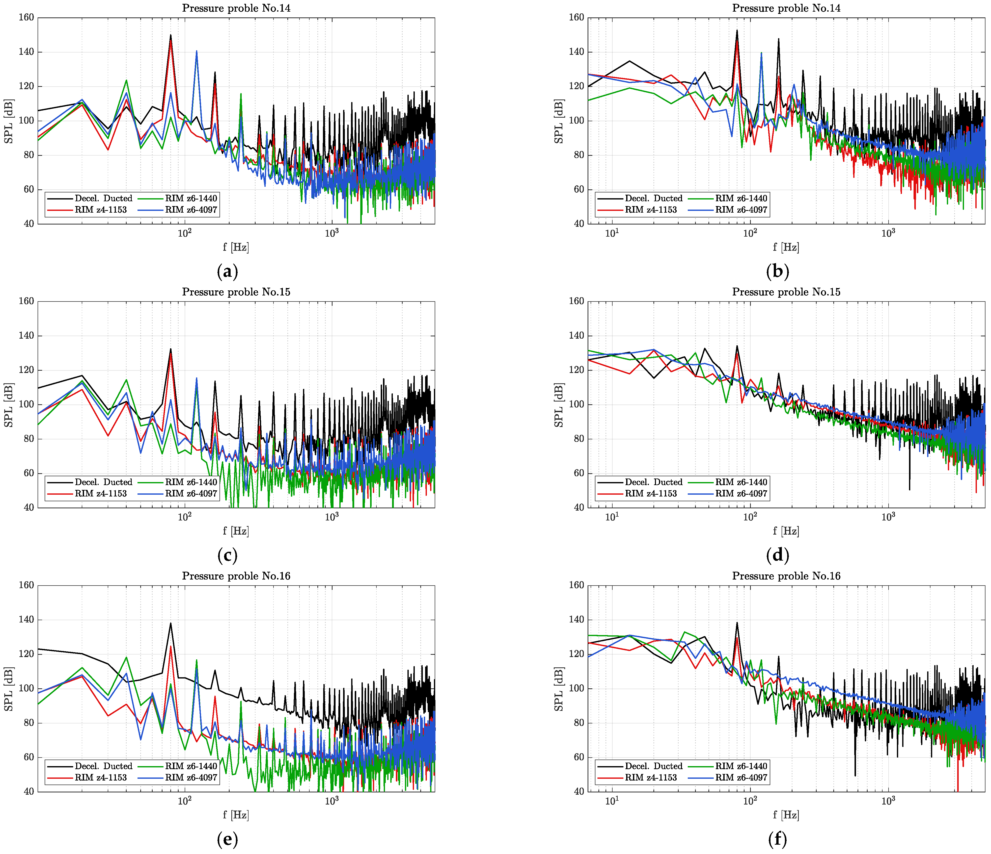
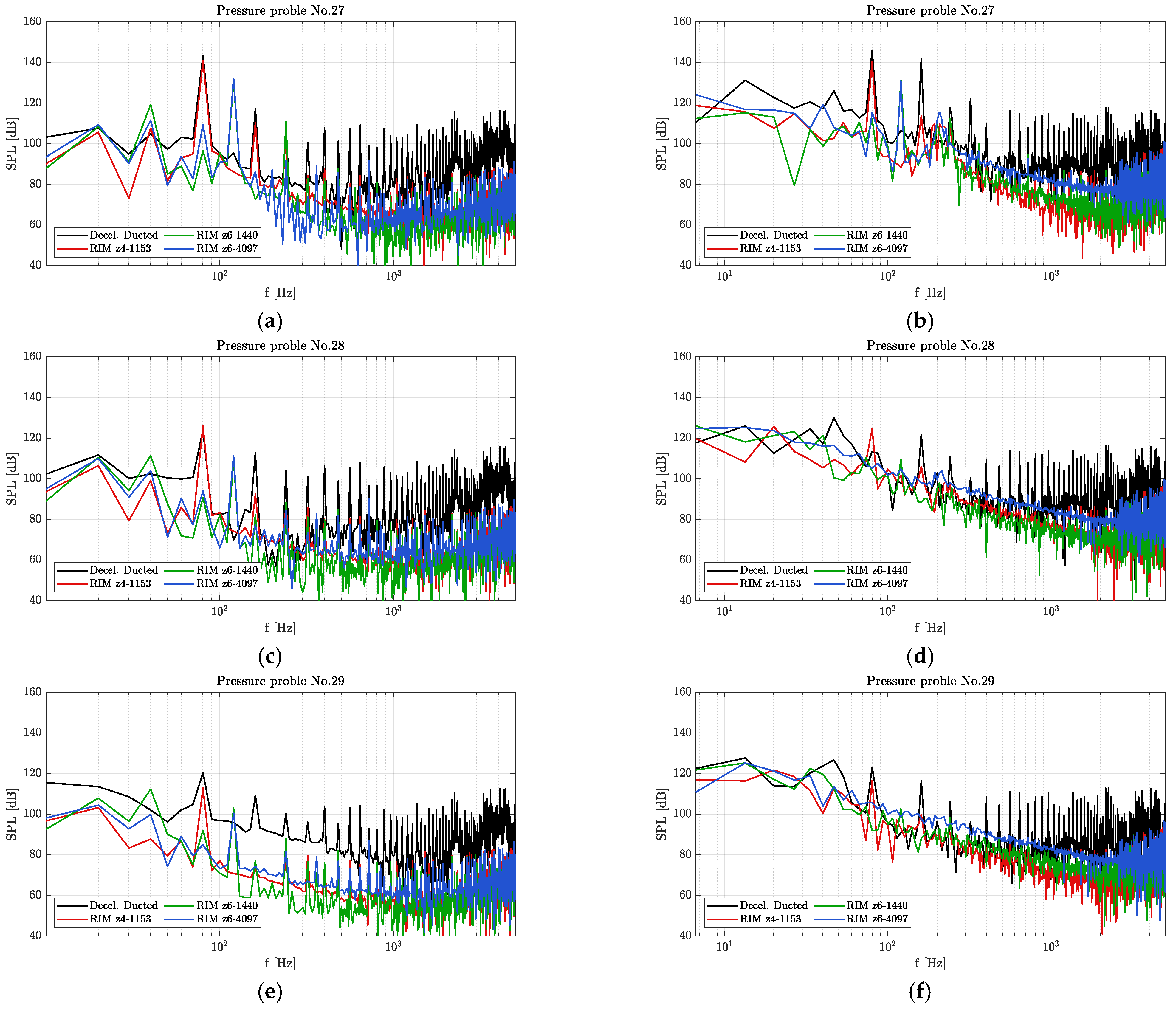
The comparison of spectra gives an overview on the strength of vortices in addition to evidencing the overall lower level of radiated noise granted by this “gap-less” geometrical configuration of the propulsors. To this end, as shown in Figure 13, during calculations the pressure has been sampled on a certain number of points close to the propellers and their trailing wakes. Time histories have then been processed using Fourier analysis to extract the most relevant characteristics in the frequency domain. Results, collected again using both RANSE and IDDES, are shown for a selection of sampling points in Figure 14 and Figure 15. RANSE and IDDES show relatively similar values, at least in terms of blade harmonics and for points relatively close to the propeller. Far from the propeller plane, where the vortical structures predicted by RANSE are less intense and there is a lack of all the secondary vortices and mutual interactions, levels predicted by RANSE are lower as well as the broadband is underestimated. For a comparative analysis, in any case, both sets of data are reliable since tonal noise is the most relevant (and reliable) feature in the non-cavitating conditions under investigation.
Especially for the reference ducted propeller, tonal noise is easily recognizable since it has the highest value among the propulsors for any of the investigated locations. The first and the second harmonics are particularly intense. If the first is obviously ascribable to the passage of (one of the) tip vortices, in the uniform inflow conditions under investigation, all of the other harmonics can be ascribed to the tip and trailing wake interactions. The presence of a severe leakage vortex doubles the frequency of the pressure disturbance, while all the other vortices interactions determine the higher frequency peaks that characterize the spectra of the reference ducted propeller. Among the RIM-driven thrusters, only z4–1153 is easily comparable to the reference propeller thanks to the same number of blades. The first harmonic has a very similar value, especially for sampling points close to the propeller (p14 and p27) where the displacement effect, at the very same load, has greater influence. The second harmonic, on the contrary, is much lower. The absence of strongly coherent secondary helical structures (like the leakage vortex) interacting with the tip vortex, as well as the relative weakness of the tip vortex itself, prevents the periodic interactions visible instead in the vortical structures of the ducted propeller. On the contrary, the chaotic behavior of secondary vortices allocates the generally lower pressure fluctuations on higher and non-tonal frequencies, as always observable by the comparison between RANSE (mainly tonal components) and IDDES.
Six-bladed RIM-driven thrusters perform even better, at first as a consequence of the different number of blades. The first harmonic of z6–1440 and z6–4097 has very similar values between the two propellers and it is sensibly lower than that of the four-bladed geometries simply because the same total load is distributed on six blades, with an obvious reduction in the displacement effect. Moreover, it practically vanishes for locations slightly more distant to the propulsors. For p15, p16, p28, and p29 it is almost indistinguishable in the spectra. Only z6–1440, between the two, has slightly higher values and this is reasonably ascribable to the presence of the apparently more coherent vortical structures of Figure 9d, which are instead completely absent in the case of z6–4097. The second tonal has a decay rate even faster and with the exception of the sampling point closest to the propeller (p14), it is indistinguishable in the spectra for both the thrusters.

5. Conclusions

IDDES simulations were used to analyze and compare tip vortices, leakage vortices, and trailing vortical wakes of a set of RIM-driven thrusters derived from a reference ducted propulsor. These geometries, which were obtained from an optimization process, were designed to maximize the propulsive efficiency and reduce the risk of cavitation while providing exactly the same thrust at the same advance coefficient. This permitted a fair comparison, both in terms of wake features and induced pressure pulses, crucial to verify the superior performances of RIM-driven thrusters in terms of the radiated noise ascribable to the hydrodynamic behavior of the propulsors.
Numerical analyses evidenced a different wake destabilization mechanism, related mainly to the interaction of generally weaker tip vortices with the shear layer originated by the nozzle, wake roll-up at root, and stable root vortices, and an overall reduction in the pressure pulses radiated by this type of propulsors.
For practically all the three RIM-driven thrusters under investigation, different in number of blades (one four-bladed, two six-bladed) and radial loading, the tip–duct mutual inductance instability was the primary mechanism of wake destabilization. The completely sealed gap between the blade tip and the internal nozzle surface, in addition to avoiding the (usually stronger) leakage vortex, promoted the development of a very weak tip vortex due to the absence of suction side/pressure side cross-flow. The “helical” coherence (and stability) of these weak tip vortices was easily influenced by the interaction with the ring-shaped vortex sheet from the nozzle trailing edge. This is the reason for the observed duct-induced vortices, which originate from a distortion of the duct shear layer caused by the blade trailing wakes and tip vortices. The stronger is the tip vortex, the stronger and stabler are these induced vortices. In the case of the reference-ducted propeller, the combined action of tip and leakage vortex generated more coherent helical structures, in any case overlapped by the bridging secondary vortices that made the wake of the ducted propeller unstable already from the trailing edge. In the case of the RIM-driven thrusters, the presence of the tip vortex only barely favored this coherence, and indeed in the wake of these propulsors it was easier to identify vortex ring rather than helical vortices.
Depending on the pitch distribution, very different shapes of the trialing wake were observed, some of which promoted wake/vortex interaction and wake fragmentation. These phenomena, typical of heavily loaded propellers, were observed, in the inner portion of the wake rather than on the outer, in correspondence with the free root vortices that, for current geometries, behave like the tip vortices of conventional open propellers. The relatively small load at hub, in any case, prevented any destabilization of the root vortices, which were predicted, within the limitations of the current numerical setup and discretization, to be very stable.
Pressure sampling, in the end, confirmed the better (hydrodynamic) performances of this kind of propulsor configurations in terms of radiated noise. Even if calculations accounted only for open water, non-cavitating induced pressures in the near field to minimize the numerical issues associated to the prediction of hydrodynamic noise, the comparison with the reference ducted propeller showed levels of induced pressures sensibly lower for all the three thrusters. In particular, the tonal noise starting from the second harmonics was minimized, reasonably as a consequence of the weakening of the vortical structures and of the chaotic dynamics started by the secondary vortices.
Combined with the overall better performances in terms of postponement of cavitation inception and risk of tip vortex cavitation made possible by the avoidance of strong tip vortices that this type of propulsors have shown, RIM-driven thrusters appear as a convincing alternative to ducted propellers to mitigate side effects like radiated noise without sacrificing the propulsive efficiency.

Funding

This research received no external funding.

Institutional Review Board Statement

Not applicable.

Informed Consent Statement

Not applicable.

Data Availability Statement

Restrictions apply to the availability of these data. Data were partially obtained from FINCANTIERI S.p.A. Those data are not publicly available being part of an industrial-funded project.

Acknowledgments

This research was partially supported by the European Union—NextGenerationEU. Piano Nazionale di Ripresa e Resilienza, Missione 4 Componente 2 Investimento 1.4 “Potenziamento strutture di ricerca e creazione di “campioni nazionali di R\&S” su alcune Key Enabling Technologies”. Code CN00000023—Title: “Sustainable Mobility Center (Centro Nazionale per la Mobilità Sostenibile—CNMS)”. Views and opinions expressed are, however, those of the author(s) only and do not necessarily reflect those of the European Union or European Commission. Neither the European Union nor the granting authority can be held responsible for them.

Conflicts of Interest

The authors declare no conflict of interest.

References

  1. Saunders, H.E. Hydrodynamics in Ship Design; Society of Naval Architects and Marine Engineers: Jersey City, NJ, USA, 1957. [Google Scholar]
  2. Lebedev, E.L.; Pershitz, R.Y.; Rusetskiy, A.A.; Avrashkov, N.S.; Tarasyuk, A.B. Ship Steering Units; Sudostroenie: Leningrad, Russia, 1969. [Google Scholar]
  3. Yakovlev, A.Y.; Sokolov, M.A.; Marinisch, N.V. Numerical design and experimental verification of a RIM-driven thruster. In Proceedings of the Second International Symposium on Marine Propulsors, SMP2011, Hamburg, Germany, 15–17 June 2011. [Google Scholar]
  4. Baltazar, J.; Falcão de Campos, J.A.C.; Bosschers, J. Open-water thrust and torque predictions of a ducted propeller system with a panel method. Int. J. Rotating Mach. 2012, 2012, 474785. [Google Scholar] [CrossRef]
  5. Gaggero, S.; Tani, G.; Viviani, M.; Conti, F. A study on the numerical prediction of propellers cavitating tip vortex. Ocean Eng. 2014, 92, 137–161. [Google Scholar] [CrossRef]
  6. Sparenberg, J.A. On optimum propellers with a duct of finite length. J. Ship Res. 1969, 13, 129–136. [Google Scholar] [CrossRef]
  7. Slijper, C.A.; Sparenberg, J.A. On optimum propellers with a duct of finite length II. J. Ship Res. 1970, 14, 296–299. [Google Scholar] [CrossRef]
  8. Mishkevich, V. Theoretical modeling of ring propulsor in steady flow. In Proceedings of the SNAME Propeller and Shafting Symposium, Virginia Beach, VA, USA, 20–21 September 2000. [Google Scholar]
  9. Kinnas, S.A.; Chang, S.H.; He, L.; Johannessen, J.T. Performance prediction of a cavitating RIM driven tunnel thruster. In Proceedings of the First International Symposium on Marine Propulsors, Trondheim, Norway, 22–24 June 2009. [Google Scholar]
  10. Zhai, S.; Jin, S.; Chen, J.; Liu, Z.; Song, X. CFD-based multi-objective optimization of the duct for a rim-driven thruster. Ocean Eng. 2022, 264, 112467. [Google Scholar] [CrossRef]
  11. Liu, L.; Jiang, W.; Liu, Z.; Yu, R.; Bian, T. Multi-objective optimization of shaftless rim-driven thruster based on ISIGHT. J. Phys. Conf. Ser. 2022, 2369, 012023. [Google Scholar] [CrossRef]
  12. Gaggero, S. Numerical design of a RIM-driven thruster using a RANS-based optimization approach. App. Ocean Res. 2020, 94, 101941. [Google Scholar] [CrossRef]
  13. Dubas, A.J.; Bressloff, N.W.; Sharkh, S.M. Numerical modelling of rotor–stator interaction in rim driven thrusters. Ocean Eng. 2015, 106, 281–288. [Google Scholar] [CrossRef]
  14. Song, B.W.; Wang, Y.J.; Tian, W.L. Open water performance comparison between hub-type and hubless rim driven thrusters based on CFD method. Ocean Eng. 2015, 103, 55–63. [Google Scholar] [CrossRef]
  15. Cao, Q.M.; Hong, F.W.; Tang, D.H.; Hu, F.L.; Lu, L.Z. Prediction of loading distribution and hydrodynamic measurements for propeller blades in a rim driven thruster. J. Hydrodyn. 2012, 24, 50–57. [Google Scholar] [CrossRef]
  16. Jiang, W.; Shen, X.; Liu, L.; Bian, T. Numerical analysis of the effect of the blade number on the hydrodynamic performance of shaftless rim-driven thruster. Proc. IMechE Part M J. Eng. Maritimi Environ. 2023, 237, 588–596. [Google Scholar] [CrossRef]
  17. Lin, J.; Yao, H.D.; Wang, C.; Su, Y.; Yang, C. Hydrodynamic performance of a rim-driven thruster improved with gap geometry adjustment. Eng. Appl. Comput. Fluid Mech. 2023, 17, 2183902. [Google Scholar] [CrossRef]
  18. Widnall, S.E. The stability of a helical vortex filament. J. Fluid Mech. 1972, 54, 641–663. [Google Scholar] [CrossRef]
  19. Sipp, D.; Lauga, E.; Jacquin, L. Vortices in rotating systems: Centrifugal, elliptic and hyperbolic type instabilities. Phys. Fluids 1999, 11, 3716–3728. [Google Scholar] [CrossRef]
  20. Felli, M.; Di Felice, F.; Guj, G.; Camussi, R. Analysis of the propeller wake evolution by pressure and velocity phase measurements. Exp. Fluids 2006, 41, 441–451. [Google Scholar] [CrossRef]
  21. Felli, M.; Camussi, R.; DI Felice, F. Mechanisms of evolution of the propeller wake in the transition and far fields. J. Fluid Mech. 2011, 682, 5–53. [Google Scholar] [CrossRef]
  22. Ahmed, S.; Croaker, P.; Doolan, C.J. On the instability mechanisms of ship propeller wakes. Ocean Eng. 2020, 213, 107609. [Google Scholar] [CrossRef]
  23. Kumar, P.; Mahesh, K. Large eddy simulation of propeller wake instabilities. J. Fluid Mech. 2017, 814, 361–396. [Google Scholar] [CrossRef]
  24. Posa, A. The dynamics of the tip vortices shed by a tip-loaded propeller with winglets. J. Fluid Mech. 2022, 951, A25. [Google Scholar] [CrossRef]
  25. Posa, A.; Broglia, R.; Balaras, E. The dynamics of the tip and hub vortices shed by a propeller: Eulerian and Lagrangian approaches. Comput. Fluids 2022, 236, 105313. [Google Scholar] [CrossRef]
  26. Qin, D.; Huang, Q.; Pan, G.; Shi, Y.; Han, P.; Dong, X. Effect of the duct and the pre-swirl stator on the wake dynamics of a pre-swirl pumpjet propulsor. Ocean Eng. 2021, 237, 109620. [Google Scholar] [CrossRef]
  27. Qin, D.; Huang, Q.; Shi, Y.; Pan, G.; Shi, Y.; Dong, X. Comparison of hydrodynamic performance and wake vortices of two typical types of pumpjet propulsor. Ocean Eng. 2021, 224, 108700. [Google Scholar] [CrossRef]
  28. Gong, J.; Guo, C.-Y.; Zhao, D.-G.; Wu, T.-C.; Song, K.-W. A comparative DES study of wake vortex evolution for ducted and non-ducted propellers. Ocean Eng. 2018, 160, 78–93. [Google Scholar] [CrossRef]
  29. Muscari, R.; Di Mascio, A. Detached Eddy Simulation of the flow behind an isolated propeller. In Proceedings of the Third International Symposium on Marine Propulsors, Lanceston, Australia, 5–8 May 2013. [Google Scholar]
  30. Gaggero, S.; Ferrando, M. Wake Instabilities of Tip-Loaded Propellers: Comparison between CLT and “New Generation” CLT Configurations. J. Mar. Sci. Eng. 2023, 11, 112. [Google Scholar] [CrossRef]
  31. Gaggero, S.; Martinelli, M. Design and analysis of pumpjet propulsors using CFD-based optimization. Ocean Eng. 2023, 277, 114304. [Google Scholar] [CrossRef]
  32. Spalart, P.R.; Allmaras, S.R. A One-Equation Turbulence Model for Aerodynamic Flows. In Proceedings of the 30th Aerospace Sciences Meeting and Exhibit, Reno, NV, USA, 6–9 January 1992. AIAA Paper 92-0439. [Google Scholar]
  33. The OpenFOAM Foundation. OpenFOAM 8.0 Users Guide. Available online: https://openfoam.org/release/8/ (accessed on 6 March 2023).
  34. Gaggero, S.; Rizzo, C.M.; Tani, G.; Viviani, M. EFD and CFD design and analysis of a propeller in decelerating duct. Int. J. Rotating Mach. 2012, 2012, 823831. [Google Scholar] [CrossRef]
  35. Squires, K.D. Detached-eddy simulation: Current status and perspectives. In Direct and Large-Eddy Simulation V; Springer: Dordrecht, The Netherlands, 2004; pp. 465–480. [Google Scholar]
  36. Shur, M.L.; Spalart, P.R.; Strelets, M.K.; Travin, A.K. A hybrid RANS-LES approach with delayed-DES and wall-modelled LES capabilities. Int. J. Heat Fluid Flow 2008, 29, 1638–1649. [Google Scholar] [CrossRef]
  37. Villa, D.; Gaggero, S.; Tani, G.; Viviani, M. Numerical and experimental comparison of ducted and non-ducted propellers. J. Mar. Sci. Eng. 2020, 8, 257. [Google Scholar] [CrossRef]
  38. Saffman, P.G. The velocity of viscous vortex rings. Stud. Appl. Math. 1970, 49, 371–380. [Google Scholar] [CrossRef]
  39. Li, H.; Huang, Q.; Pan, G.; Dong, X. Wake instabilities of a pre-swirl stator pumpjet propulsor. Phys. Fluids 2021, 33, 085119. [Google Scholar] [CrossRef]
  40. Li, H.; Huang, Q.; Pan, G.; Dong, X.; Li, F. Effects of Blade Number on the Propulsion and Vortical Structures of Pre-Swirl Stator Pump-Jet Propulsors. J. Mar. Sci. Eng. 2021, 1, 1406. [Google Scholar] [CrossRef]
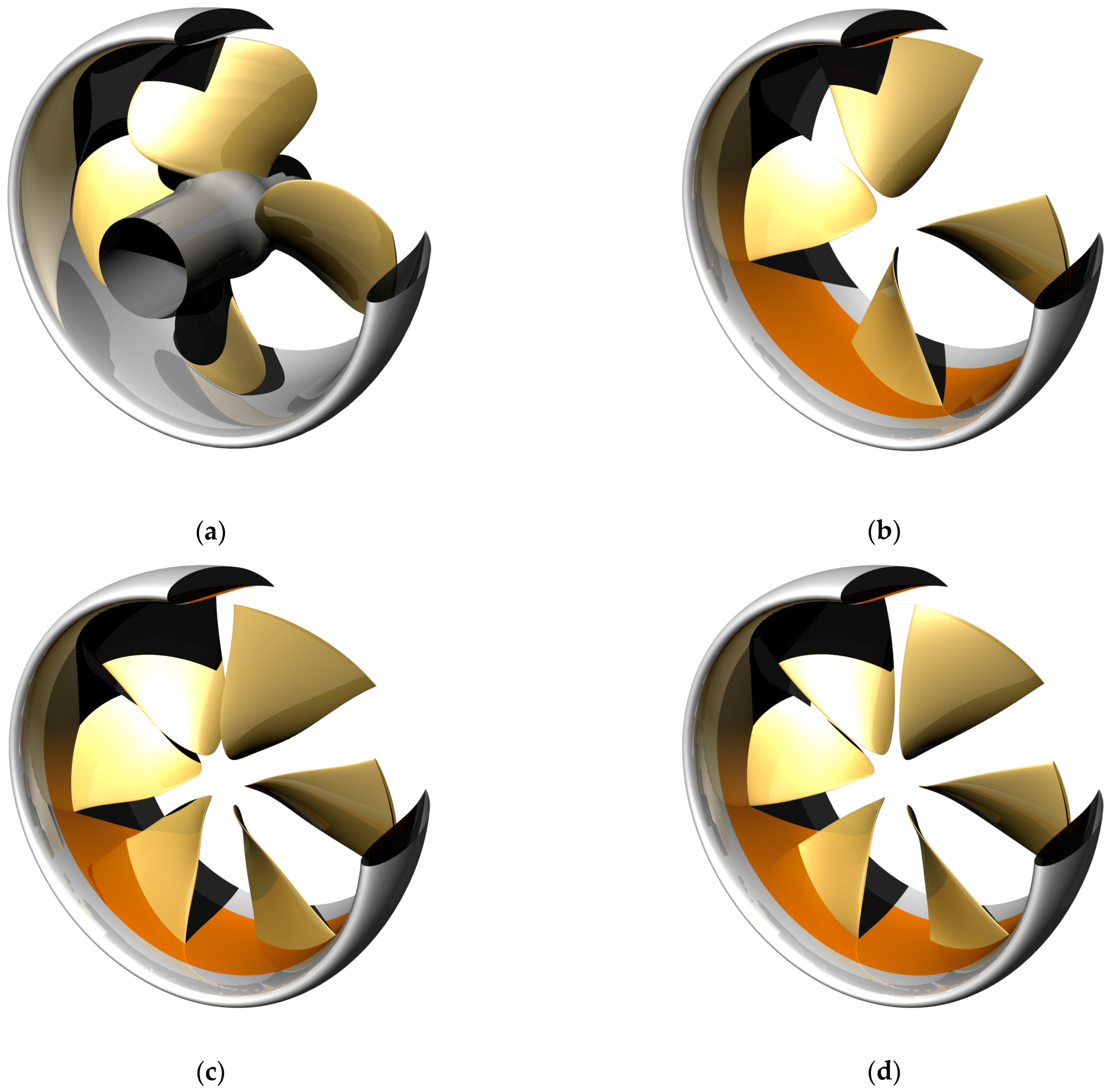
Figure 1. Geometries of the propulsors under investigation: (a) reference-ducted propeller; (b) RIM z4–1153; (c) RIM z6–1440; (d) RIM z6–4097.
Jmse 11 01659 g001
Figure 2. Computational grid for IDDES analyses of z6–4097 propulsor: (a) coarse; (b) medium; (c) fine (Reference).
Jmse 11 01659 g002
Figure 3. Distribution of vorticity (magnitude) computed by IDDES on the longitudinal plane: (a) coarse; (b) medium; (c) fine (Reference).
Jmse 11 01659 g003
Figure 4. Suction-side normalized pressure distributions by IDDES: (a) reference-ducted propeller; (b) RIM z4–1153; (c) RIM z6–1440; (d) RIM z6–4097.
Jmse 11 01659 g004
Figure 5. Vortical structures (isosurface of Q). Reference decelerating ducted propeller. (a) RANSE, Q = 5000 s−2; (b) IDDES, Q = 5000 s−2; (c) RANSE, Q = 25,000 s−2; (d) IDDES, Q = 50,000 s−2.
Jmse 11 01659 g005
Figure 6. Distribution of vorticity (magnitude) on the longitudinal plane. Reference-decelerating ducted propeller. (a) RANSE; (b) IDDES. Nozzle shape partially camouflaged for confidentiality reasons.
Jmse 11 01659 g006
Figure 7. Vortical structures (isosurface of Q). RIM-driven thruster z4–1153. (a) RANSE, Q = 5000 s−2 (b) IDDES, Q = 5000 s−2; (c) RANSE, Q = 50,000 s−2; (d) IDDES, Q = 50,000 s−2.
Jmse 11 01659 g007
Figure 8. Distribution of vorticity (magnitude) on the longitudinal plane. RIM-driven thruster z4–1153. (a) RANSE; (b) IDDES. Nozzle shape partially camouflaged for confidentiality reasons.
Jmse 11 01659 g008
Figure 9. Vortical structures (isosurface of Q). RIM-driven thruster z6–1440. (a) RANSE, Q = 5000 s−2 (b) IDDES, Q = 5000 s−2; (c) RANSE, Q = 50,000 s−2; (d) IDDES, Q = 50,000 s−2.
Jmse 11 01659 g009
Figure 10. Distribution of vorticity (magnitude) on the longitudinal plane. RIM-driven thruster z6–1440. (a) RANSE; (b) IDDES. Nozzle shape partially camouflaged for confidentiality reasons.
Jmse 11 01659 g010
Figure 11. Vortical structures (isosurface of Q). RIM-driven thruster z6–4097. (a) RANSE, Q = 5000 s−2. (b) IDDES, Q = 5000 s−2. (c) RANSE, Q = 25,000 s−2. (d) IDDES, Q = 50,000 s−2.
Jmse 11 01659 g011
Figure 12. Distribution of vorticity (magnitude) on the longitudinal plane. RIM-driven thruster z6–4097. (a) RANSE. (b) IDDES. Nozzle shape partially camouflaged for confidentiality reasons.
Jmse 11 01659 g012
Figure 13. Sampling points for pressure pulses monitoring.
Jmse 11 01659 g013
Figure 14. Sound pressure levels at different near- and far-field locations. (a) Sampling point 14, RANSE; (c) sampling point 15, RANSE; (e) sampling point 16, RANSE; (b) sampling point 14, IDDES; (d) sampling point 15, IDDES; (f) sampling point 16, IDDES.
Jmse 11 01659 g014
Figure 15. Sound pressure levels at different near- and far-field locations. (a) Sampling point 27, RANSE; (c) sampling point 28, RANSE; (e) sampling point 29, RANSE; (b) sampling point 27, IDDES; (d) sampling point 28, IDDES; (f) sampling point 29, IDDES.
Jmse 11 01659 g015
Table 1. Main geometrical characteristics of the test case propulsors.
Referencez4–1153z6–1440z6–4067
Number of blades4466
Diameter (model scale)0.23 m0.23 m0.23 m0.23 m
rhub/R0.30---
AE/AO0.7250.6060.7890.728
c/D 0.7R0.4980.3410.2850.277
fmax/c 0.7R0.02460.01860.01560.0191
P/D 0.7R1.3541.0981.0771.166
Table 2. Boundary conditions for OpenFOAM calculations.
PatchVelocityPressure υ ^ υ t   or   μ t / ρ
InletFixed p n = 0 Fixed   4 · υ Fixed   f v 1 · υ ^ = 6.07 · 10 7
Outlet U n = 0 Fixed   ( p = 0 ) υ ^ n = 0 Fixed   f v 1 · υ ^ = 6.07 · 10 7
Blades, Nozzle (hub, shaft)No-slip p n = 0 0 with wallfunction
(kqRWallFunction)
0 with wallfunction
(nutUspaldingWallFunction)
Lateral cylindrical surfaceNo-slip p n = 0 υ ^ n = 0 Fixed   f v 1 · υ ^ = 6.07 · 10 7
Inner rotating/outer fixed region interfaceArbitrary Mesh Interface (AMI)Arbitrary Mesh Interface (AMI)Arbitrary Mesh Interface (AMI)Arbitrary Mesh Interface (AMI)
Table 3. Adopted discretization schemes.
Scheme
Time Crank Nicolson   ( 0.9 ) ,   Δ t e q u i v a l e n t = 0.5   d e g .
Divergence2nd order for momentum (linearUpwind)
2nd order for turbulence (limitedLinear with Sweby limiter)
GradientsGauss with multi-dimensional limiter (cellMDLimited)
LaplacianGauss with linear interpolation and a limiter
Table 4. Grid convergence of IDDES calculations. Due to confidentiality reasons, values are made non-dimensional, respectively, with the measured (100%) thrust and torque of the reference ducted propeller. KT is the total thrust (blades, duct, and RIM), 10KQ accounts for the parasitic torque of the RIM.
GridCellsKT10KQ η o
Coarse12,824,49694.20%105.52%0.581
Medium21,026,81294.45%104.92%0.586
Fine (Reference)43,660,17094.93%104.55%0.591
Table 5. Performances of the propulsors under investigation. Comparison between RANSE and IDDES on reference grid. Due to confidentiality reasons, values are made non-dimensional, respectively, with the measured (100%) thrust and torque of the reference-ducted propeller. KT is the total thrust (blades, duct, and RIM), 10KQ accounts for the parasitic torque of the RIM.
Reference Ductedz4–1153z6–1440z6–4097
KT10KQ η o KT10KQ η o KT10KQ η o KT10KQ η o
RANSE100.5%106.4%0.61598.4%105.4%0.60897.5%109.2%0.58198.8%106.9%0.602
IDDES96.7%103.7%0.60794.5%103.1%0.59792.5%105.5%0.57194.9%104.5%0.591
Disclaimer/Publisher’s Note: The statements, opinions and data contained in all publications are solely those of the individual author(s) and contributor(s) and not of MDPI and/or the editor(s). MDPI and/or the editor(s) disclaim responsibility for any injury to people or property resulting from any ideas, methods, instructions or products referred to in the content.