Article

Optimization of Ship’s Navigational Parameters to Improve the Stowage and Securing Criteria of Non-Standardized Cargo in Ships

by
José M. Pérez-Canosa
1,
José A. Orosa
1,*,
Francesc Xavier Martínez de Osés
2 and
Fco. Javier Lama-Carballo
1
1
Department of Navigation Sciences and Marine Engineering, University of A Coruña, Paseo de Ronda, 51, 15011 A Coruña, Spain
2
Ciencia e Ingeniería Náuticas, Universidad Politécnica de Cataluña, 08034 Barcelona, Spain
*
Author to whom correspondence should be addressed.
J. Mar. Sci. Eng. 2023, 11(9), 1782; https://doi.org/10.3390/jmse11091782
Submission received: 23 August 2023 / Revised: 7 September 2023 / Accepted: 10 September 2023 / Published: 12 September 2023
(This article belongs to the Section Ocean Engineering)

Abstract

:
General cargo ships are the most numerous in the merchant fleet. In these vessels, the stowage and securing of non-standardized cargo must be designed prior to being shipped. Furthermore, during sea navigation, the shipmaster must be confident that the secured cargo is safe in any weather conditions. One of the goals of the present research is to provide helpful guides to ship operators about the optimal navigational parameters. Despite different criteria being followed by the shipping industry to calculate the rolling motion accelerations, relevant accidents and losses related to an inadequate securing arrangement still occur. Firstly, this paper analyzes and compares the IMO’s and classification societies’ criteria, obtaining relevant results about the different safety levels along the ship’s dimensions. Secondly, it obtains a novel mathematical model of angular transverse acceleration, considering the sea state conditions and navigational parameters. For this reason, it investigates the combinations of optimization of these parameters. Finally, it proposes novel 3D surface graphs as being easy, useful, and quick to be interpreted by shipmasters when sailing in certain sea state conditions, to know if the limits of the maximum securing arrangement are exceeded and predict the ship’s optimal speed and heading in order to set out.

1. Introduction

In the merchant fleet, general cargo ships are the most numerous [1]. Furthermore, despite strong containerization in the last decades, the millions of dead-weight tons of general cargo ships in the world fleet have increased over recent years [2].
Unfortunately, despite all the loss prevention criteria available, a high number of relevant accidents occur due to inadequate securing arrangements on board and/or deficient stowage and securing of cargo [3]. The result is damages to or loss of cargo, damages to the ship’s structure, and even the causing of injury and loss of life [4,5]. As cargo losses and their consequences happen for some reason, the way to prevent this in the future the occurrence of such accidents is a proper design of stowage and the securing of the cargo. For that, it becomes essential that all people involved in these tasks are aware of the risks arising from the shipment of non-standardized cargo on board ships. Among all these people, the shipmaster stands out as the person ultimately responsible for the safety of transport, including the safety of the environment, the ship, its crew, and its cargo. In the maritime business, the pressure to reduce shipping costs is very high and, for that reason, this aspect sometimes causes strong discussions between the ship’s staff, the charterer, and the cargo surveyor who has to approve the stowage and cargo lashing. However, in addition to the approval and the issuance of the corresponding certificates, the shipmaster must ensure that all transported cargoes are properly stowed and secured to sail in any weather condition according to the corresponding criteria. Furthermore, whilst underway, in case of a change in the weather conditions, he should know how to proceed to reduce the amplitude and/or frequency of ship motions in order to reduce the accelerations and avoid cargo shifting, with the aim of continuing with safe navigation.
In non-standardized cargo shipping, homogeneous stowage and securing criteria can be difficult to establish, because of differences in ships’ and cargoes characteristics. Then, the scope of the present paper is the accelerations sustained by non-standardized cargo shipped on-board general cargo ships, multi-purpose and heavy-lift vessels where the stowage and securing arrangement must be designed prior to being shipped, i.e., other than solid and liquid bulk cargoes. Furthermore, the studied motion is the rolling motion because it is the largest in the magnitude of the six degrees of freedom of a ship [6]. Therefore, once it is decided that the ship is suitable for the intended cargo and vice versa, it is necessary to plan carefully the best stowage location on board, which will affect the final securing arrangements according to the calculations of forces [7].
According to the selected criteria and the navigational area wherein the ship will sail, the shipping industry decides the best available position to stow the cargo on board and then carries out the design of securing arrangements. Given the variety of available criteria that can be followed, the legislation, the standards, and the guidelines should be continuously subject to discussion, with the single focus of improving the safety of maritime transport. For that mission, it is essential to develop novel models and recommendations of navigational parameters for ship operators of general cargo vessels as a tool for improving cargo security under certain weather conditions, which is one of the goals of the present paper. Shipmasters can use these new tools during sea navigation when the planned maximum conditions of the securing systems are exceeded.
Once the cargo securing method is approved and fulfilled with the ship cargo securing manual [4], the safety of the cargo, the crewmembers and its comfort, the ship and the stresses on its structures, and the environment are satisfied, at least from a theoretical point of view. However, since weather conditions can change quickly, the shipping sector in general and heavy cargo journals should be analyzed independently to meet the minimum ship’s stability and avoid cargo shifting, keeping the accelerations and forces sustained as low as possible.
The International Maritime Organization’s (IMO) most important criteria for calculating the accelerations and the securing of non-standardized cargo is the code of safe practice for cargo stowage and securing (CSS code) [8]. The calculations of this code, which remains the default methodology for calculating the forces sustained by the cargo, consider the ships’ characteristics, the location of the cargo within the ship, and the cargo mass. In the transverse motion, considered as the most important from the point of view of the sustained forces for cargo securing [5], the CSS code provides a data chart of accelerations applicable in an unrestricted area. The last version of the CSS code included a correction factor as a function of the significant wave height encountered during the sea passage. However, it is not too specific, for example, about the ship’s loading condition or the cargo stowage position concerning the ship’s center of gravity.
The classification societies and some shipping lines have their methods, based on more rigorous engineering principles, to calculate the accelerations expected during the sea passage and, consequently, to design the securing systems accordingly. These calculated accelerations mainly depend on the ship’s particulars, the stowage position, and the cargo characteristics. However, since it is unusual to perform a motion study or model test, classification societies such as DNV issue a set of motion criteria that depend on the length and beam of the ship, the block coefficient, and its natural rolling period [9]. Therefore, the simulations of a ship’s rolling motions in a seaway are necessary to predict the frequency of occurrence of excessive rolling angles or excessive transverse acceleration amplitudes [10]. In the literature, we can find much relevant research about mathematical models of nonlinear roll motion trying to predict this motion [11,12]. These works show that the external forces give rise to complex mathematical models. In this field, other researchers utilize artificial neural networks when ships sail in random beam seas [13], and other authors use neural network algorithms to predict the ship’s navigation state and ensure the overall safety of sailing in waves based on external input [6]. Gu [14] studied the utilization of the Melnikov function and the phase space flux to determine the safety of ships in random beam seas.
Therefore, as the problems caused by excessive rolling motion are well-known, the shipping industry use active and passive roll reduction devices to control it, including bilge keel, anti-rolling tank, fin stabilizer, and gyrostabilizer. In fact, a recent and very interesting research [15] proposed a new control algorithm for an active gyrostabilizer, measuring the angular rate of rolling motion by a gyro sensor. Thus, the importance for masters and ship operators of knowing the values of angular accelerations (not just total linear accelerations as established by IMO criteria) is shown. For that reason, in the present paper, in addition to studying and comparing, from a scientific point of view, the criteria of the IMO and the classification societies, new models are proposed taking into account angular transverse accelerations. Other authors [16] also point out that the prediction of roll motion is critical for the ship’s operability and safety, and is helpful to shipmaster or autopilot to make proper decisions. For that reason, they presented a data-driven methodology to provide multi-step prediction of roll motion in high sea conditions with the aid of a hybrid neural network.
Few researchers focus on the comparative study of the most common criteria followed by the shipping industry when designing the best stowage and securing arrangements on board. Furthermore, hardly any studies are available about simplified models of rolling motion in a single-degree freedom system, which can result in as simple and understandable as possible guidance for master and ship operators to make faster and safer decisions. In this sense, Begovic et al. [17] carried out a work about simplified operational guidance in excessive acceleration criterion of the IMO’s second generation intact stability criteria. This work deals with lateral acceleration experienced by people on board a bulk carrier vessel. It also shows polar diagrams identifying the safest combination of the ship’s speed and heading in a standard wave scatter table.
Similarly to the procedure followed in other investigations [18,19,20], in the present paper, once the simplified and novel mathematical model is obtained, the ship is numerically simulated in a short-time domain altering the main navigational parameters (heading and ship’s speed), whilst sailing between different sea state conditions. With this approach, the purpose is to investigate and predict the effect of altering these two navigational parameters on the angular transverse acceleration and rolling amplitudes, with the goal of helping masters and ship operators to obtain trends and make proper decisions to enhance the safety of sea passage. In other words, the objective is to use simple graphs and models to solve the stringent problem, and to find solutions as quickly as possible to decrease the transverse accelerations and the rolling amplitudes.
To guarantee a high level of safety and prevent damages, losses, and claims, the aim of this paper is, on one hand, to study and compare the main calculations criteria followed by the shipping industry (CSS and DNV) for stowage and securing the cargo on board ships based on the expected forces encountered during the sea route. In addition, it compares the results of both criteria using a real case and obtaining relevant results in terms of safety. On the other hand, it proposes a novel mathematical model of angular transverse acceleration that is valid for any ship, regardless of its ship’s particulars. This new mathematical model considers the specific sea state conditions, previously modelled by the authors. It also obtains relevant and useful results that masters and ship operators should consider during the sea voyage by altering two navigational parameters such as heading and the ship’s speed. Furthermore, these results are helpful to put into perspective the previous results obtained according to the calculation criteria that the shipping industry currently follows.
Therefore, with the proposed mathematical model, which includes the navigational parameters and the ship stability, it is possible to guarantee the safety of sea navigation by the ship operators, keeping the actual sustained transverse accelerations below the maximum accelerations for which the securing system was initially designed.

2. Materials and Methods

This section is divided into four subsections. The first and the second subsections present the mathematical models mainly followed by the shipping industry concerning stowage and securing design of general cargo on board. Specifically, the first subsection analyses the IMO tools and studies the guidelines of the classification society DNV. These guidelines are one of the strictest from the safety point of view, and, therefore, are the ones taken into account by the shipping industry [4]. The third subsection studies the novel mathematical models of angular transverse acceleration of a ship sailing between any waves coming from any direction. Finally, it shows the models of regular and trochoidal waves used in the present work.
With this approach, the first two subsections allow us to put in perspective and carry out a comparative analysis of the real and practical methods followed by the shipping industry nowadays. Obtained results will allow for obtaining advantages or disadvantages of each method, as well as determining the one that is recommended to apply on stowage and lashing schemes, from the point of view of safety cargo securing.
The third and fourth subsections study and propose the novel mathematical models of angular transverse acceleration derived from the ship’s behavior sailing between waves from a theoretical and mathematical point of view. With this approach, it is possible to compare the results of procedures followed by the industry (two first subsections) and the results obtained with the proposed models. Furthermore, it makes it possible to analyze the influence of the navigational (ship’s speed and heading) and operational (ship’s loading condition) parameters to be modified during the sea passage by the ship operators.

2.1. IMO Regulations

The IMO provides the CSS code as the main available tool in the process of calculating transverse accelerations of non-standardized cargo on board ships. Its Annex 13 considers that the accelerations, which includes the components of gravity, pitch, and heave parallel to the deck, depend on two factors. The first one is the height or vertical position of the stowage above the keel (high deck, main deck, tween deck, and lower hold). The second one is the longitudinal position referred to its length, where 0.0 is the aft perpendicular and 1.0 is the forward perpendicular. These basic transverse acceleration data apply to ships sailing without restrictions, at a speed of 15 knots, with a length of 100 m, and with a relationship between the beam (B) and the metacentric height (GM) higher than 13.
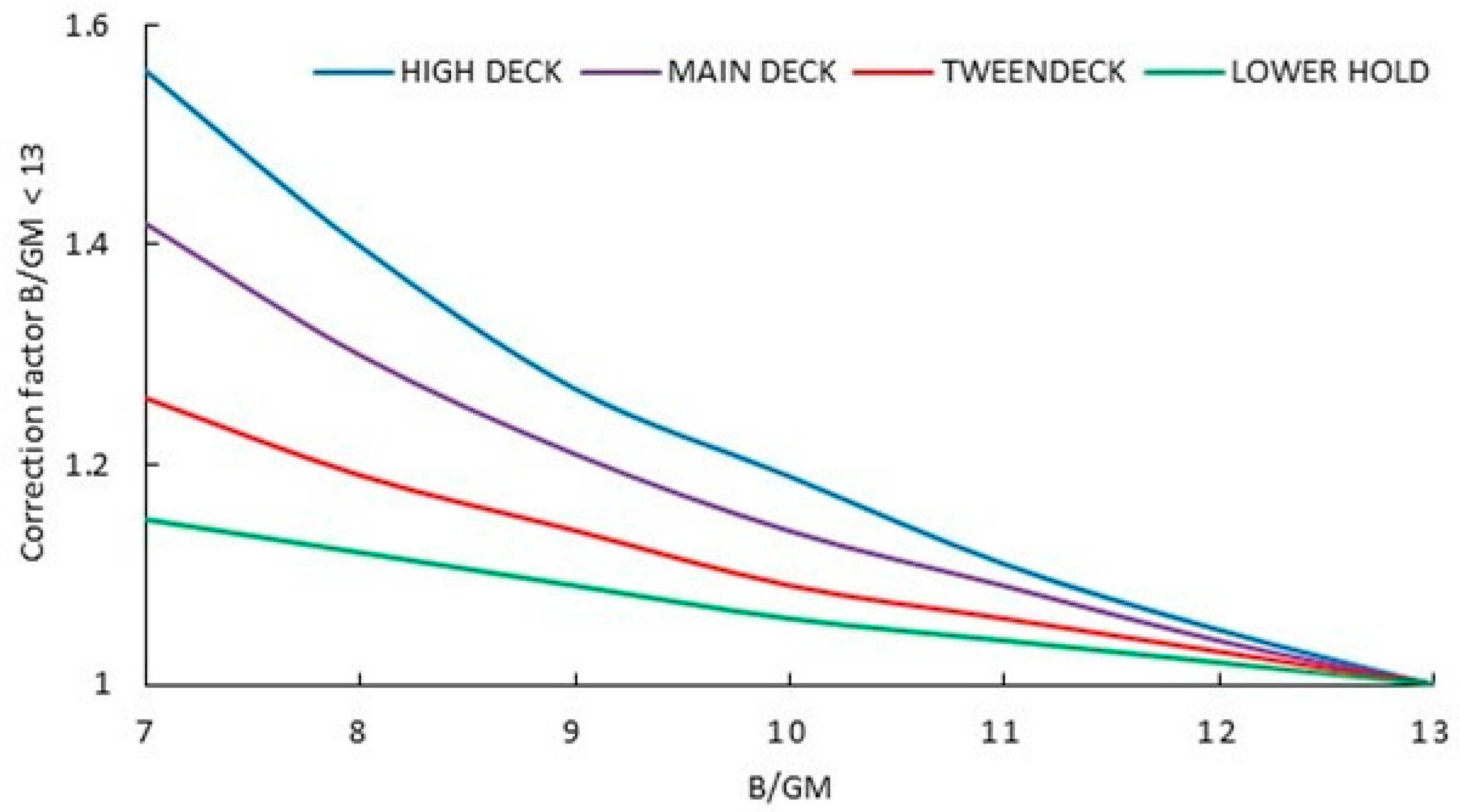
However, if ships have other dimensions or parameters, the CSS code includes two tables of correction factors. The first one, represented in Figure 1, allows for correcting the transverse acceleration by speed and length, and the second one, shown in Figure 2, applies a correction factor for cases of the relationship of the beam (B) and metacentric height (GM) being less than 13.
Furthermore, as it is known, the transverse accelerations are directly related to the ship’s roll natural period, i.e., the loading condition, and the maximum rolling angle, which is determined by the encountered weather condition. However, there is no specific reference to these parameters in the CSS code. Therefore, in this matter, the IMO’s most important regulation that allows linking the rolling angle with the encountered weather conditions is the International Code on Intact Stability, 2008 [21,22]. Precisely, some severe accidents of parametric roll on board modern containerships and RoRo ships triggered a new revision of the IS code. Therefore, using the IS code, the ship’s maximum rolling angle because of the influence of constant relative wind and the waves can be calculated according to the following Equation.
θ ( degrees ) = 109 K X 1 X 2 r s ,
where K factor is a function of the bilge shape and if the ship has or does not have bilge keels; factor X1 depends on the relationship between the beam (B) and the draught (d); factor X2 is determined by the block coefficient (Cb); factor s depends on the ship roll natural period (Td); and factor r is obtained using the following:
r = 0.73 + 0.61 ( K G d ) d ,
where KG is the height of the ship’s center of gravity from the keel and d is the draught.

2.2. Classification Society Guidelines

Although different rolling angles cause different transverse accelerations and then different forces sustained by the cargo stowed on board, as was previously mentioned, the CSS code accelerations tables do not consider explicitly the amplitude of the rolling angle experienced by the ship during the sea route. Furthermore, the CSS code does not take into account the different transverse accelerations depending on the stowage position of cargo along the beam. Therefore, considering the lack of specific information in the CSS code according to the ship’s conditions and the specific stowage position, in this research, and for validation purposes, the guidelines of classification society DNV are used. The DNV guidelines are some of the strictest and most specific guidelines in dealing with the forces sustained by cargo on board ships and sailing in different areas [23]. Therefore, according to DNV [24], the tangential acceleration (at) during the roll motion can be calculated as follows:
at = θ 2 π Td 2 Rr ,
where θ is the rolling angle; Td is the ship’s double natural period; and Rr is the distance from the center of gravity of the ship to the center of mass of the cargo, on its stowage position.
From Equation (3), the corresponding angular acceleration (aw) can be expressed:
aw = θ 2 π Td 2 ,
However, during the rolling motion, when the ship is heeled with a non-zero angle, the cargo is also subjected to gravity acceleration, which is not included in Equation (3). In this circumstance, the gravity acceleration (g) can be decomposed into a force parallel to the deck, and another force perpendicular to the deck [23]. In our case study, we are interested in the acceleration parallel to the deck (gX), which adopts the following equation:
g X = g sin θ ,
Therefore, as it can be deducted from Equation (5), this component of gravity acceleration parallel to deck is value constant and independent of the cargo stowage position.

2.3. Ship’s Rolling Motion Influenced by Constant Trochoidal Waves

After analyzing the different methods currently used in practice by most of the shipping industry, this subsection studies, from a theoretical point of view, the behavior of a ship sailing between regular and trochoidal waves coming from any constant direction. This approach obtains the novel mathematical models of angular transverse acceleration which, in addition to analyzing the optimal ship’s navigational parameters, allow us to put into perspective the methods followed by the industry.
The ship’s rolling motion at non-zero speed and under the influence of regular and trochoidal waves coming from any constant direction had already been studied previously by the authors [25,26], although research about the corresponding angular acceleration was not conducted. According to this research, the rolling motion (rad) can be expressed as follows:
θ = θ M e λ 1 t T d cos 2 π T d t + λ 1 2 π sin 2 π T d t + θ M W sin α cos β sin 2 π T e t β 1 T d 2 T e 2 ,
where θM is the initial maximum angle of roll (rad); λ1 represents the damping factor as a consequence of the water resistance; θMW is the maximum wave slope (rad); α is the angle formed between the ship’s center line (heading) and the direction of the waves coming from any constant direction (rad); Te is the encounter period (s); and β (rad) is defined as follows:
tan β = λ 1 π T e T w 1 T e 2 T w 2 ,
where Tw, the waves’ period, Td, and time (t) is expressed in seconds (s).
As was commented previously, in the IMO and classification societies’ guidelines, the transverse accelerations are analyzed as the main parameter to be taken into account in the stage of securing design. For this reason, in the present research it was necessary to obtain the transverse acceleration corresponding to Equation (6). For that, in the first moment, the corresponding angular velocity (rad/s) is obtained, which can be expressed as follows:
θ = θ M e λ 1 t Td 2 π Td sin 2 π Td t 2 π Td λ 1 2 π cos 2 π Td t θ M λ 1 Td e λ 1 t Td cos 2 π Td t + + λ 1 2 π sin 2 π Td t θ MW 2 π Te cos β 2 π Te t cos β sin α Td 2 Te 2 1 ,
Consequently, after deriving Equation (8), the corresponding transverse acceleration (rad/s2) is the following:
θ = 2 θ M λ 1 T d e λ 1 t Td 2 π Td sin 2 π Td t 2 π Td λ 1 2 π cos 2 π Td t θ M e λ 1 t Td 2 π T d 2 cos 2 π Td t + 2 π T d 2 λ 1 2 π sin 2 π Td t + + θ M λ 1 Td 2 e λ 1 t Td cos 2 π Td t + λ 1 2 π sin 2 π Td t θ MW 2 π Te sin β 2 π Te t cos β sin α Td 2 Te 2 1 ,

2.4. Waves’ Study

Nowadays, at the time of plotting the passage planning, all deck officers have available, and well in advance, the weather forecast for the intended sea route. In the same way, this information is also available during the design of the cargo-securing system. Therefore, if the parameters of the expected waves are known in advance, the master can adjust the ship’s navigational parameters (heading and ship’s speed) to keep the maximum transverse acceleration below the limits that the stowage and securing system cannot exceed. In addition, if the sea state conditions change during the sea voyage, and the maximum permissible accelerations are exceeded, the shipmaster can carry out some action to decrease the accelerations sustained by the cargo. One of them is to reinforce the cargo lashing system, if possible, from a technical and safety point of view, or to improve the ship’s behavior by altering the heading and/or the ship’s speed.
Then, it is necessary to know the characteristics of the waves full spectrum that a ship can encounter during the sea passage. These characteristics are defined by parameters such as wavelength (Lw), translation velocity (Vw), and period (Tw). According to empirical observations shown in the literature [27], the trochoidal and regular waves full spectrum can be classified into 21 types of regular and trochoidal waves, corresponding to 21 periods. The direct relationship between these three parameters (Lw, Vw, and Tw) and the maximum wave slope (θMW), which is constant for rough and smooth seas, has allowed us to identify and classify all parameters for each wave period (Tw). Therefore, according to previous research of the authors [28], the calculated relationship between the wavelength (Lw) and period (Tw), and between velocity (Vw) and period (Tw) are the following:
Lw ( m ) = 1 . 5838 Tw 2 0 . 5558 Tw + 1 . 4737 ,
Vw ( m s 1 ) = 0 . 0009 Tw 2 + 0 . 7632 Tw + 0 . 366 9 ,
In both Equations (10) and (11), a precision above 99% for the determination factor was obtained. Furthermore, the following expression was used in order to set out the relationship between the maximum wave slope (θMW), the wavelength (Lw), and the wave height (Hw).
sin ( θ MW ) = π Hw Lw ,
In Figure 3 is a flow chart defining the proposed mathematical model and the optimization of ship variables (navigational parameters and ship’s stability). As one of the top events, the angular velocity (w) is also added, a parameter that could be obtained, although it is not analyzed in the present paper.

3. Results

According to the approach taken in this paper, this section provides a comparative study of results from two points of view. Firstly, and through a real case study, it compares the results in tangential transverse accelerations according to the CSS code and the DNV methods. For that mission, it shows the procedures and calculations followed to the considered ship’s particulars, considered as representative as possible of the characteristics of a certain shipping fleet. Afterward, using the novel mathematical models proposed, the angular transverse accelerations are compared with the corresponding obtained in the two previously mentioned methods. Finally, the influence of navigational parameters (heading and ship’s speed) and their optimizations, which can be altered at any time by ship operators, is studied in a short-time domain.

3.1. Case Study

For comparative purposes between the tangential transverse accelerations calculated according to the CSS code and the corresponding as per DNV guidelines, the basic transverse acceleration data are considered, i.e., a ship with a length of 100 m, sailing at 15 knots, and with a relationship B/GM > 13.
For that, it was necessary to calculate the approximate distance between the center of gravity of referenced ship (considered as the center of rotation) and the different stowage positions using the Pythagoras theorem in space.
In this rectangular box of the Pythagoras theorem, the length and the height depend on the different analyzed stowage positions, and the width is always the ship’s semi-beam, as is considered the worst position from the point of view of accelerations sustained. Although the ship’s center of gravity does not always coincide with the center of rotation, according to the literature, it can be stated that if the ship’s center of gravity is above the waterline, the oscillation axis is below the center of gravity, whereas if the ship’s center of gravity is low enough, the oscillation axis passes above it [29]. For this reason, for the present study and considering that its position is variable, it can be considered that the ship’s center of gravity coincides with the center of rotation.
Regarding the used variables, from the CSS code it is deduced that the center of the gravity of the ship of reference is placed, in a vertical way, in the vicinity of the double bottom (lower transverse acceleration registered) and, in a longitudinal way, at 40% or 50% of the length from aft (100 m length). In our calculations, it was considered 40% length from aft, as we understand it would be the most frequent position considering that ships usually sail with aft trim.
In order to apply the society classification’s equations mentioned above, it is necessary to select the ship’s particulars to be as representative as possible of general cargo vessels fleet similar to the referenced in the CSS code. The ship’s particulars were selected after analyzing the ship’s particulars of a high number of ships that are representative of the fleet of general cargo ships of 100 m length, and are included in Table 1.
Furthermore, according to the literature, the GM (m) of general cargo ships is about 7% of the beam [24,30], so in this study case, the GM would be 1.1 m. For the roll natural period, the formula used is:
T d = 2 π k 1 g G M ,
where k1 is the radius of rotation of the ship’s displacement with respect to the longitudinal axis passing through the center of gravity (m); g is the gravity (m/s2); and GM is the metacentric height (m). Therefore, for a certain ship’s loading condition, the value of the rolling period (Td) is constant, regardless of the value of the amplitude roll. Then, the mean angular velocity changes directly with the maximum roll. In any case, there are several empirical equations relating Td (s) with GM (m), and some of them are the following [30].
T d = 0.77 B G M ,
In fact, the IS code [21] consider that the Td (s) can also be calculated as follows:
T d = 2 C B G M ,
where in Equation (15):
C = 0.373 + 0.023 B d 0.043 L w l 100 ,
Knowing that (B) is the beam (m), (d) the draught (m), and (Lwl) the length at the waterline (m).
Therefore, in Table 1 are included the main representative parameters of a general cargo ship with a 100 m length used in the present research.
These real ship’s parameters were considered after analyzing the ship’s particulars of a representative number of general cargo ships with an overall length of 100 m.
Regarding the simulated initial conditions, the following parameters were considered:
  • Ship in upright position;
  • 12° as average initial angle of rolling.

3.2. Comparative Results Analysis between the IMO and the Classification Societies Methods

The present comparative analysis considers a significant wave height of 12.0 m as it is considered the worst condition that a ship can find during sea navigation because, according to the CSS code, no correction factor is applied.
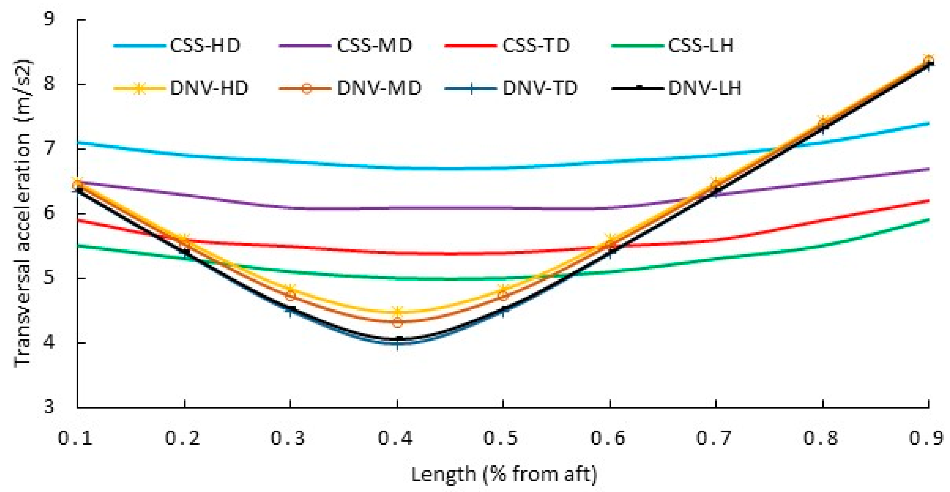
Using the values of Table 1, and as per Equation (1), the maximum angle of the roll according to the IS code result is 19.58°. Then, with a rolling angle of 19.42° and following Equations (3) and (4) of DNV guidelines, the corresponding force of gravity acceleration parallel to the deck (Equation (5)) and the tangential acceleration (Equation (3)) corresponding to each stowage position of the IMO basic transverse acceleration data is calculated. The results for high deck (HD), main deck (MD), tween deck (TD), and lower hold (LH) are depicted in Figure 4. The angular acceleration according to Equation (4) is 0.0995 rad/s2, and although it is a parameter that is not explicitly included in either the IMO or DNV, it will be taken into account in the following subsection for comparative purposes.
The CSS code does not specify if the length (100 m) is between perpendiculars or not, although as per the figure included in the same code, it seems that it is between perpendiculars. For this reason, as the given transverse accelerations are included between 0.1 and 0.9 of length from the aft, it is considered that these extreme positions are referenced only to cargo holds. Therefore, assuming that the ship’s center of gravity is about 0.4 of length from aft, and in the vicinity of the double bottom, the longitudinal distance to the different sections is calculated by sections of 10 m. In the vertical direction, the distance between the ship’s center of gravity and the cargo’s center of gravity is calculated according to parameters included in Table 1, and in the high deck and main deck, the cargo’s center of gravity is 2 m above both. These results of comparison between transverse accelerations using the CSS code and using the DNV guidelines for the ship of reference can be observed in Figure 4.
From Figure 4 it can be concluded that there are significant differences in results, due to the DNV guidelines including equations that allow us to calculate in a more precise way the accelerations in the exact stowage positions, which, in turn, is a function of the ship dimensions.
In the CSS code, the transverse accelerations of different heights (HD, MD, TD, and LH) hardly vary along the ship’s length. However, if the distance (Rr) from the center of cargo mass to the axis of rotation (center of gravity) is taken into account, as it is using the DNV guidelines, the differences between the accelerations of the positions closest to the axis of rotation and those furthest away are very considerable. This can be considered reasonable if we start from the premise that the center of gravity of the ship is considered as the axis of rotation, then this point would be in a static position.
Another remarkable result of the DNV guidelines is that the maximum acceleration difference between different heights (vertical stowage positions) is very insignificant, being the maximum difference just in the vertical axis of rotation. From this point, towards the fore and aft sections, the accelerations on different vertical stowage positions tend to be convergent. This is explained because the only different parameter in the Pythagoras Theorem in space is the height.
Furthermore, following the CSS code, the best vertical position for stowing the cargo is on the lower hold and although this fact can have reasonable results, it is not common that a ship has a center of gravity just over the double bottom. In this situation, the ship would be a very ‘stiff’ ship, being very uncomfortable for crew members and leading to excessive acceleration stresses on cargo lashing. For this reason, assuming a reasonable KG of 4.0 m, and according to calculations of the DNV, is observed that in the vicinity of the ship’s center of gravity, the transverse accelerations are lower in the tween deck than in the lower hold, due to the fact that the distance to the lower hold is higher than to the tween deck.
These results would not justify the extra securing arrangement required by the CSS code in the extreme forward position on the high deck concerning the lower hold. However, in both cases, and in the extreme forward position (80% and 90% of length from aft), the required forces to be counteracted as per the CSS code would be lower than calculated as per the DNV guidelines, despite the given transverse accelerations in the CSS code including components of gravity, pitch, and heave parallel to the deck. Therefore, it cannot be concluded that the CSS code establishes the maximum values as a safety margin in all cases. Furthermore, near the axis of rotation, as per the DNV guidelines, the cargo sustains lower accelerations than required by the CSS code, and then the securing effort would be excessive according to the CSS code.

3.3. Ship’s Rolling Motion Sailing in a Resistant Environment and Receiving Successive Trochoidal Waves from Any Constant Direction

Although our simulations analyzed the waves’ full spectrum, due to extension purposes of the paper and to be as representative as possible, the present subsection only studies the wave period (Tw) of 12, which corresponds to a wavelength (Lw) of 222.87 m and a wave height (Hw) of 7.42 m. The characteristics of these waves can be considered sufficiently representative of rough sea conditions that ships can encounter, corresponding to a seven-degree Douglas scale.
Regarding the ship’s navigational parameters (ship’s speed and heading), all headings (α) from head seas to following seas were studied, at intervals of 20°. Moreover, a = 090° was also included because sailing in beam seas is considered a very special situation.
The simulated ship’s speeds (Vs) ranged from the static condition to 22 knots, at intervals of 5 knots, and starting from zero knots. As in the simulations carried out in the previous subsections, the considered natural rolling period (Td) is 12 s, and the initial maximum angle of the roll is 12°, considered representative enough for this fleet type. This angle is also a reference rolling angle in the IMO stability calculations [21]. The damping factor considered (l1) of water resistance is 0.015. In the simulations, the wind is constant and relative to a certain ship’s heading. Furthermore, the influence of wind in the rolling motion is included in the initial angle of rolling (12°), because the result of a constant wind is a permanent list to leeward.
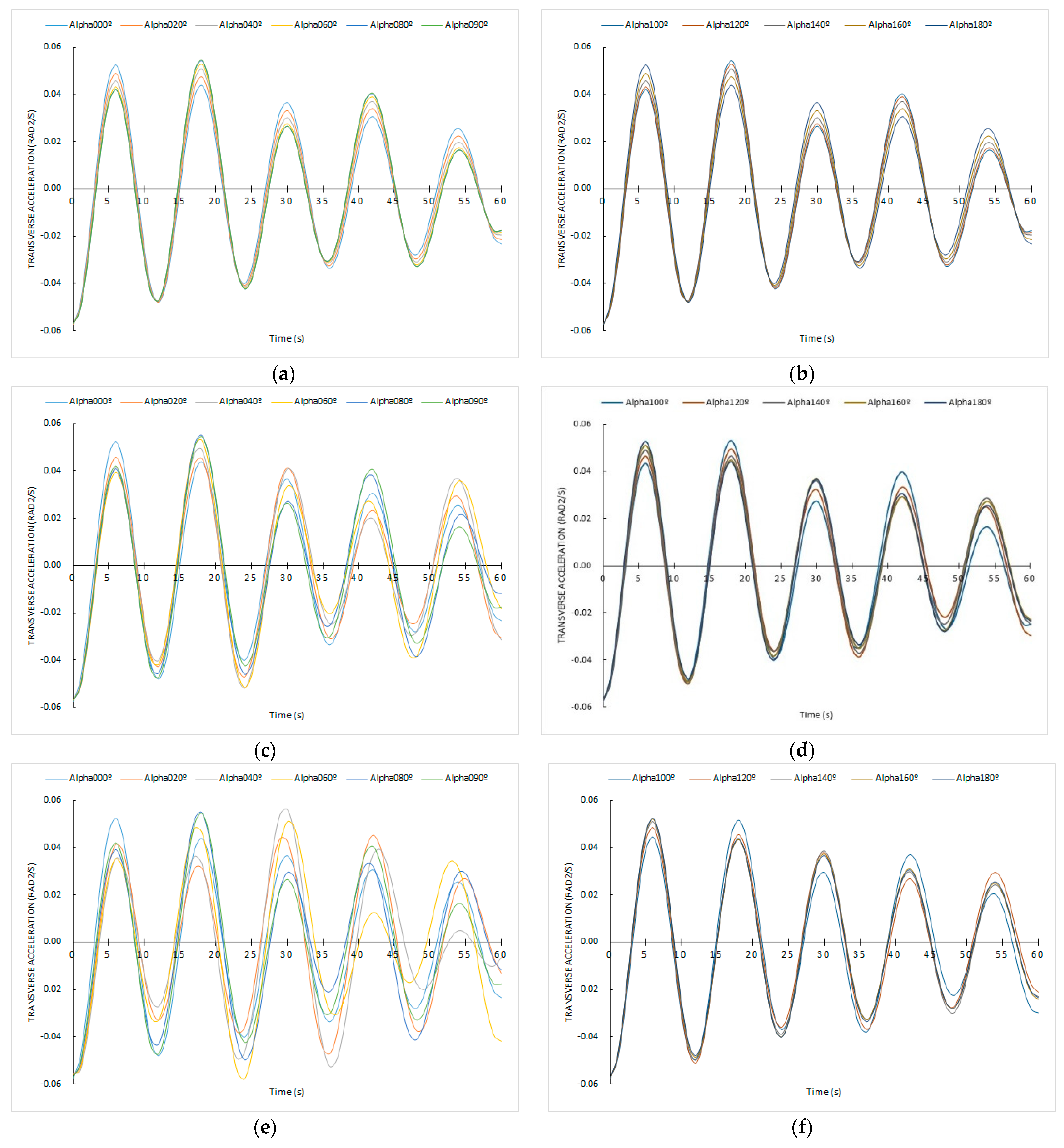
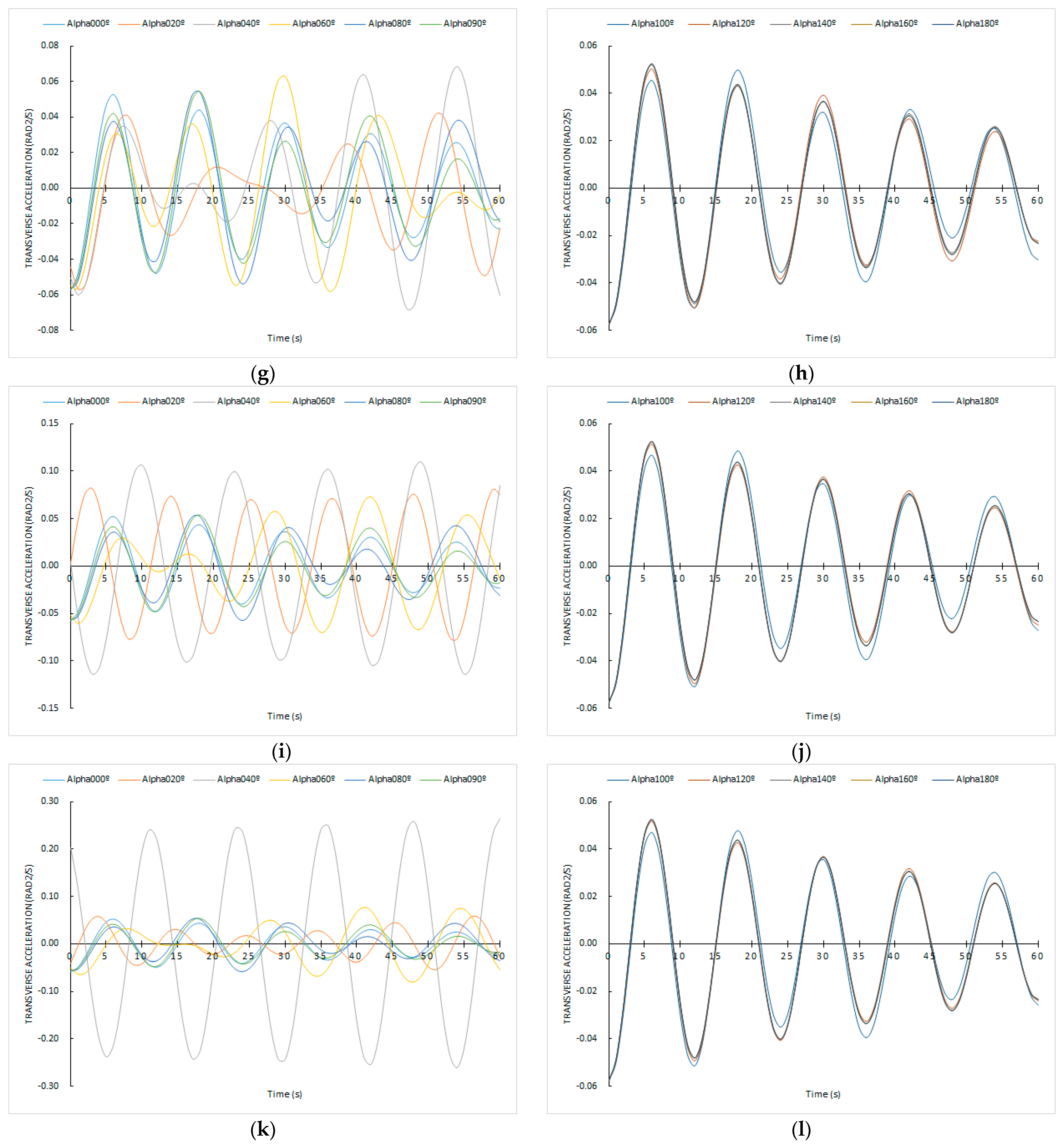
Then, according to Equation (9), in Figure 5 are plotted, in a short-time domain (60 s), the transverse angular accelerations for the mentioned cases. There, and for clarifying purposes, the results for each ship’s speed (Vs) are divided into two graphs with different headings, from head seas (000°) to beams seas (090°), and from beam seas (090°) to following seas (180°).
From Figure 5 it is observed that for Vs = 0.0 knots, Vs = 5.0 knots, Vs = 10 knots, and Vs = 15 knots, the registered angular accelerations are lower than 0.06 rad/s2, i.e., lower than the angular acceleration calculated previously according to the CSS code and DNV, which is 0.0995 rad/s2. For higher ship speeds, there are some situations where this angular acceleration is even higher than 0.10 rad/s2. For instance, for Vs = 20 knots, only a very specific situation is exceeded, which is sailing with a α = 040°, i.e., received the waves by the bow. In this situation, the acceleration presents a rather harmonious appearance, unlike in the case of α = 060°, when the acceleration’s behavior is more erratic and reaches values considerably lower than with α = 040°.
When Vs = 22 knots and α = 040°, from the first moments, angular accelerations higher than 0.20 rad/s are reached and periodically repeated, i.e., more than the double according to the CSS code and the DNV, which can compromise the overall safety of the sea transport. That is, in view of this remarkable result, the master or ship operators can reduce considerably the accelerations sustained (even achieving lower than 0.0995 rad/s2) by only changing the ship’s heading 020°. This alteration in the ship’s heading when sailing in very rough seas can be reasonable so as not to affect the ship’s economic operation negatively.
Furthermore, with any ship’s speed, from α = 090° (beam seas) to α = 180° (following seas), the difference between the maximum angular accelerations reached is very almost negligible, with a harmonic and cushioned appearance from the first moments. What is more, the absolute values of acceleration reached are very similar for any ship’s speed, which is a very relevant conclusion. In this matter, in our several simulations there is no sudden decrease in the maximum accelerations sustained when 090° < α < 180° until the Tw = 5 s or lower. What is more, if the Tw is not in the mentioned range (Tw ≤ 5 s), the appearance is very similar, being harmonic and damped in the time domain.
However, for α values between 000° (head seas) and 090° (beam seas), significant differences in the accelerations’ behavior are observed. For the ship’s speeds of 0.0 knots, 5 knots, and 10 knots, a harmonic and cushioned performance is shown, with the higher differences in the maximum accelerations between different α angles reached sailing at 10 knots. However, some erratic values are obtained sailing at the higher ship’s speeds. In some cases, for Vs = 15 knots the maximum accelerations are not achieved at the first moments, despite the damping effects of water resistance. From the theoretical point of view raised in the present subsection, this is an important result, although it could be thought that the tendency of the rolling motion and accelerations is to be damped, the combination of the ship’s navigational parameters sailing under the influence of certain waves overcomes the effect of waver resistance. Moreover, when the ship sails at 15 knots and with α = 020° a very erratic situation is registered, where the acceleration tends to be zero in the first 30 s, but from 30 s onwards, the acceleration values are progressively increasing. This ship’s behavior can give the ship operators a false sense of safety in the first few moments. A similar situation is observed with Vs = 20 knots and α = 060°.
Moreover, for α = 000° (head seas), α = 090° (beam seas), and α= 180° (following seas) it is observed that the sustained transverse accelerations in each of these conditions are the same, regardless of the ship’s speed. Although the results obtained with α = 000° and α = 180° could be expected, the fact that no difference is registered at different ship’s speeds when α = 090° can be considered a relevant conclusion. What is more, from this theoretical point of view, and under the influence of the same beam waves, the cargo is sustained to the same transverse angular acceleration if the ship is anchored in a sheltered area or is sailing at high speed. Nevertheless, as is well-known, and sailing in these situations, the master would take into account the ship’s speed in order to reduce the effects of bow-flare slamming or surf-riding.
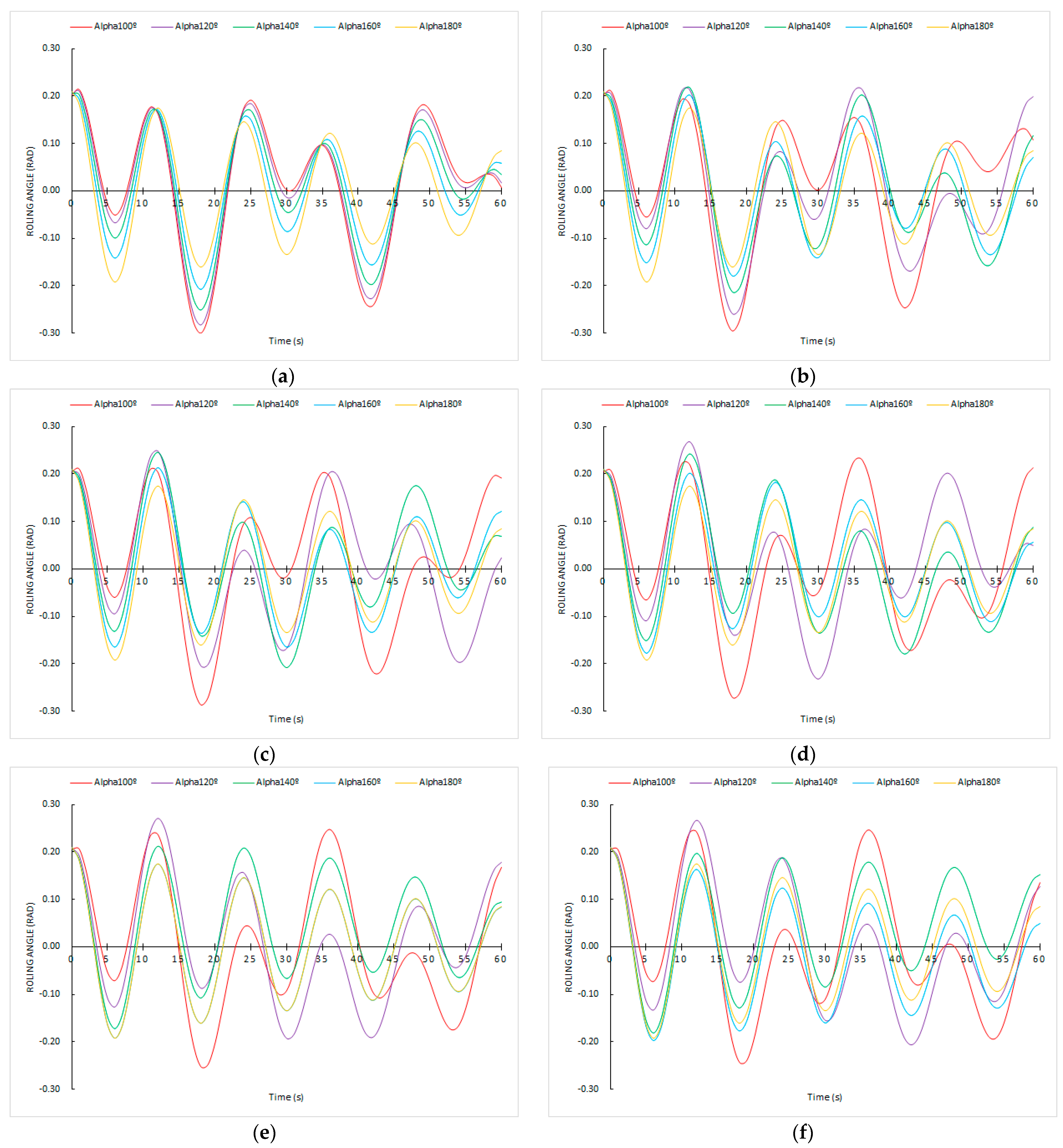
It is very relevant to notice that the angular transverse accelerations when 090° < α < 180° and sailing at any ship’s speed are always below 0.06 rad/s2, with a harmonic and damped appearance in the time domain. For this reason, and taking into account that the ship operators on board are more aware and have the means to measure the ship’s rolling angles rather than accelerations, Figure 6 displays the rolling angles that cause these angular accelerations.
In Figure 6, and for cases when 090° < α < 180°, in contrast to angular accelerations, a harmonious and damped behavior is not observed. Relevant differences in the maximum rolling angles are noted, so for the same ship’s speed, the heading set by ship operators has a significant influence on the reached rolling angle. Furthermore, in some circumstances, i.e., Vs = 0 knots and α = 120°; Vs = 10 knots and α = 100°, it is noted that the amplitude of rolling angles to opposite sides is very different between two consecutive rolling motions. What is more, in other circumstances as Vs = 0 knots and Vs = 5 knots with α = 100°, after the rolling motion to one side, the ship reaches the upright position, and then starts to roll to the same side. In other situations, such as Vs = 15 knots and Vs = 20 knots with α = 100°, after the rolling motion to one side, before reaching the upright position, the ships start to roll again to the same side. However, these relevant differences in the ship’s behavior concerning reaching the maximum rolling angles (Figure 6) do not mean important differences in angular transverse acceleration (Figure 5). In this sense, it is remarkable to note that the maximum rolling angles are not always related to the maximum transverse angular acceleration. Furthermore, the lashing design of cargo is carried out according to the accelerations sustained, instead of the maximum rolling angles.
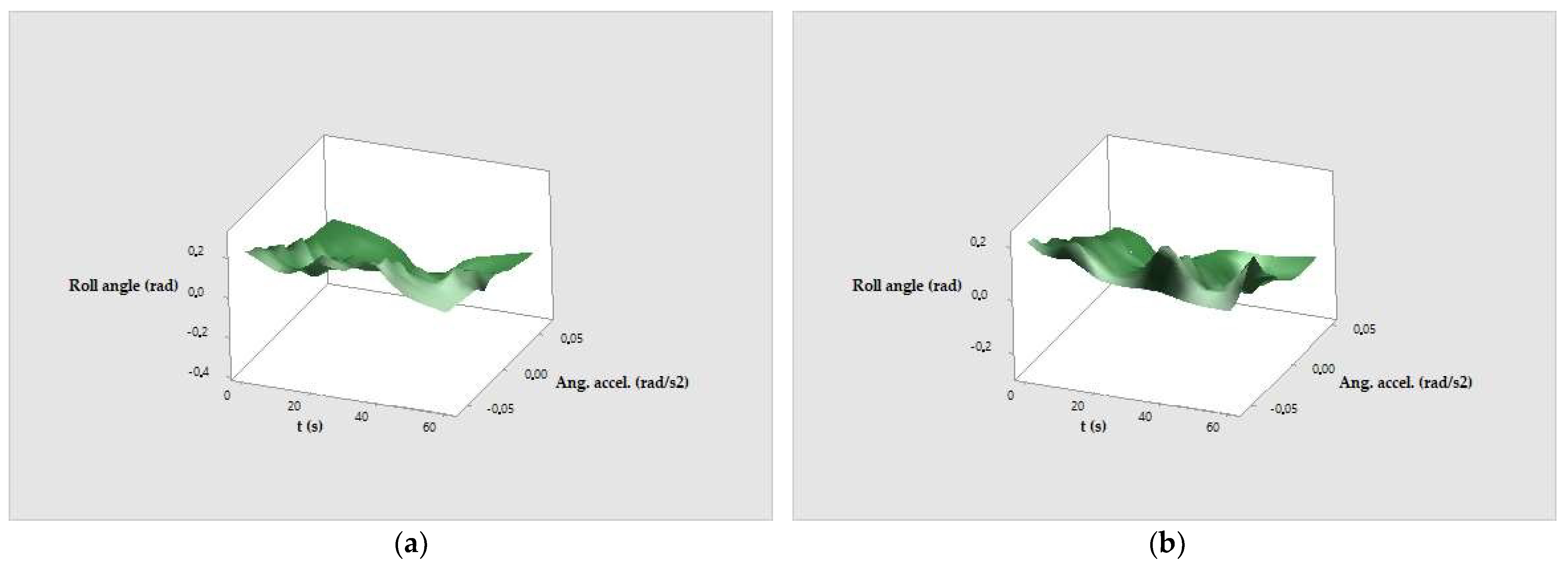
Finally, based on the novel mathematical model, in order to provide useful guides for ship operators to be used quickly during sea navigation, Figure 7 shows some examples of graphs in a 3D surface relating, in a short-time domain, the angular transverse acceleration reached with the corresponding rolling angles, which are very easily readable by the sailors. Using these useful graphs the shipmaster can know if, according to the rolling angle reached in that moment, the maximum limits of the securing system are being exceeded. If so, he can determine the optimal heading and/or ship’s speed to avoid exceeding the safety limits, without having too much negative influence on the economic operation of the ship. In this case, the results corresponding to α = 060° and 100° are plotted, with an α ship’s speed of 15 knots. There the relevant difference in sinks and valleys in the same condition along the time domain can be observed, and what is more important, the difference in the reaches transverse accelerations of the ship after a change in the heading.
Finally, and according to the obtained results, Table 2 shows a sensibility study for validation purposes of the new mathematical model with respect to the results of CSS code and DNV. It is concluded that as DNV does not consider the navigational parameters, the accelerations are above expectations according to the new model and CSS code in all cases. However, good precision is observed between the novel model and the CSS code. In fact, when the average parameters are analyzed, a precision of 4.9% is obtained. In the present cases, the only relevant difference is observed when Tw is low (6 s); α angle is high (080°); and Vship is average (10 knots), and is related to the synchronism phenomenon for this loading condition (Td = 12). This sensibility of the proposed mathematical model is a clear advantage with respect to the CSS code and DNV models because it shows the real change in the transverse accelerations and does not propose a nearly constant value as in DNV.

4. Discussion

4.1. IMO vs. DNV Criteria

According to DNV criteria, the transverse accelerations are a function of maximum rolling angle, which is caused by the weather conditions and the ship’s loading condition. If the weather conditions worsen in a leg of the sea passage, the ship operator must consider that he can continue complying with the DNV criteria altering, for example, the heading and ship’s speed in order to reduce the maximum rolling angles. However, the maximum rolling angle is not considered in the calculation of transverse acceleration according to the CSS code, and only the loading condition is included implicitly in the corrected transverse acceleration when B/GM < 13, i.e., when the ship is ‘stiff’ with great stability (lower Td). Nevertheless, when the ship has a value of Td higher (low GM), and in consequence, the maximum rolling angles are higher, the transverse acceleration should also be corrected because the lashing lines are working in excess because the ship takes an important time in recovering the righting position. However, when the Td is low, the lashing lines also suffer because of sudden and rapid accelerations in a very short time period.

4.2. About the Novel Mathematical Models

In the previously proposed novel mathematical models, the navigational parameters (ship’s speed and heading) to be altered by ship operators were analyzed. However, another operability parameter that the master can alter to modify the ship’s behavior and then the sustained transversal acceleration is the natural rolling period (Td), determined by the ship’s loading condition. A good ship’s stability, without reaching a very ‘stiff’ ship (high GM) or very ‘tender’ (low GM), is critical to the safe transport of general cargo, in particular, heavy cargo. Therefore, Figure 8a,b depict the results assuming the same sea state condition simulated previously, i.e., Tw = 12 s, a Vs = 15 knots, and considering a more ‘stiff’ ship (Td = 10 s instead of 12 s), keeping all other variables constant. It is observed that, regardless of α values, the angular transverse accelerations increase considerably, reaching nearly 0.08 rad/s2 (changing from less than 0.06 rad/s2 corresponding to the Td = 12 s). However, as is depicted in Figure 8c, the rolling angles causing this acceleration for 090° < α < 180° are lower than with Td = 12 s, as a consequence of the higher ship’s righting moment. This is a relevant conclusion because a better ship’s stability (lower Td) does not always mean a better ship’s behavior from a transverse accelerations point of view, and then, the securing of the cargo. Similarly, it can be deduced that if Td is increased, i.e., a worse ship’s stability, the angular transverse accelerations will be reduced.
For validation purposes of the novel mathematical model in a more ‘tender’ ship, in Figure 9 are included the results of transverse accelerations of a ship with the worst stability, in this case, Td = 14 s, where the patterns and conclusions commented previously can be observed.
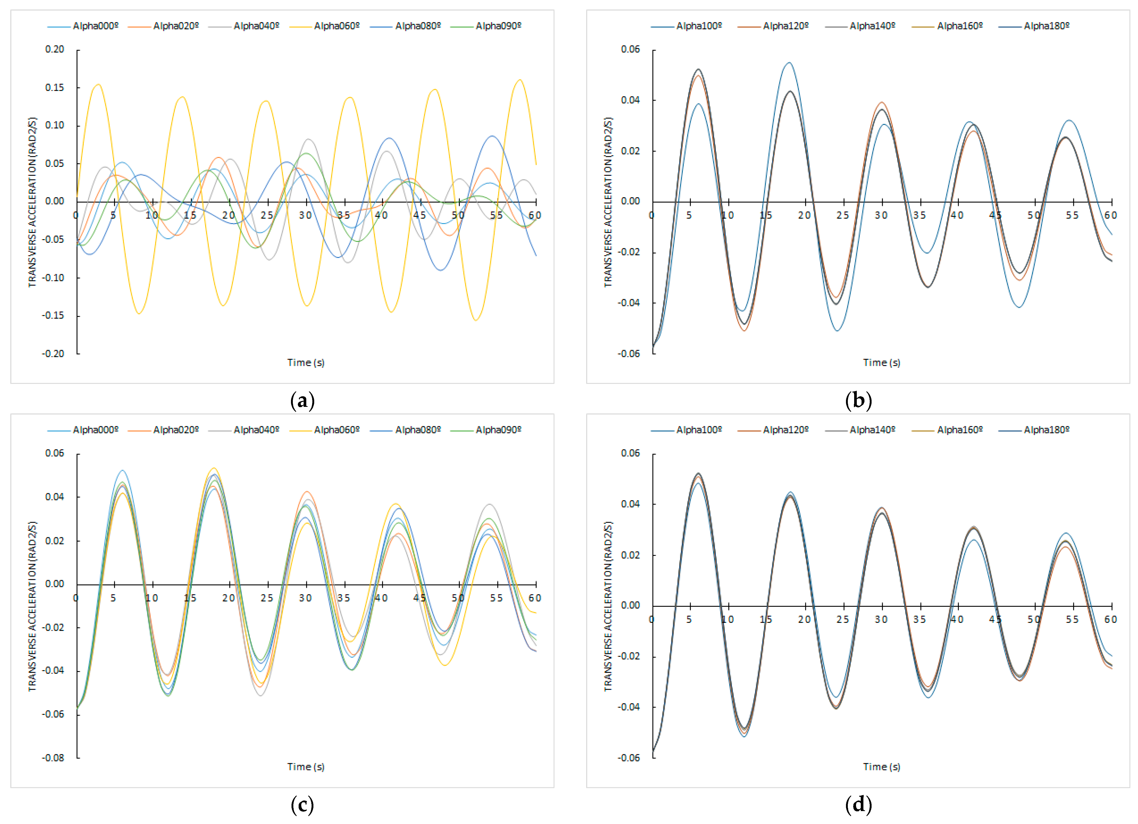
Another important issue to comment on this section is the effect of considering other sea state conditions different from the simulated in the present paper (Tw = 12 s), keeping all variables and ship’s particulars constant, with a Td = 12 s. For comparative purposes, Tw = 9 s and Tw = 15 s were selected, which, according to Equations (10) and (12), have the following parameters of Table 3.
From Figure 10a it can be concluded that when 000° < α < 090°, for smoother sea conditions (Tw = 9 s), a significant reduction in the transverse accelerations is registered. The same does not occur with worse sea conditions, although a coupling between all α values is observed, with a harmonic and damped appearance (Figure 10c).
For the cases of 090° < α < 180° (Figure 10b,d) the same results and conclusions are shown that were obtained in the previous section, which is that the maximum acceleration and the behavior are practically the same regardless of the Tw here studied.
Once the ship is under the influence of successive trochoidal and regular waves, the only parameters that the ship operator can alter to improve the ship’s behavior are the navigational parameters, such as the speed and heading, or the ship’s loading condition, the natural rolling period (Td). It is assumed that the ship’s displacement will not be varied because this can lead, for example, to infringe on the maximum load lines included in the International Convention on Load Lines, 1966 [31], in the case of increasing the ship’s displacement, or to present problems of seakeeping due to emergence of the propeller, in the case of decreasing the displacement. For that reason, the only solution to alter Td would be to carry out a shifting of weights. However, in the shipping of general cargo, and in the middle of the sea passage, the shifting of cargo to another stowage position is not reasonable from a technical and safety point of view. Then, the only solution would be to transfer the ballast vertically. However, this potential solution could affect negatively the dynamic stability due to the free surface moments. Therefore, to not exceed the maximum transverse acceleration for which the stowage and securing system was initially designed or to reduce those as much as possible, the alteration of navigational parameters is presented as the unique and best solution. Nevertheless, the master and ship operators must take into account that, given the novel results presented in the present paper, these changes should be analyzed conscientiously.

5. Conclusions

The results of the present paper show that regardless of the securing calculations criteria (IMO or classification society) followed by the shipping industry nowadays, the shipmaster must take into account that none of them provide absolute safety in terms of cargo securing, mainly because depending on the stowage position on board, the results of maximum accelerations vary from one criterion to another.
Furthermore, after obtaining and validating a novel mathematical model of angular transverse acceleration, it was concluded that the ship’s operability and navigational parameters also have a relevant influence on the accelerations sustained by the cargo, and, in consequence, in the designed securing arrangements. What is more, the proposed model shows a higher sensibility to the variables that can affect the transversal accelerations. As in this mathematical model, the specific weather conditions were also studied, and the influence of the two main navigational parameters to be easily altered by ship operators during the sea voyage were numerically investigated, concluding that no major heading changes are necessary to cause a drastic decrease in accelerations, complying with the maximum limits to which the lashing arrangements were designed. Furthermore, it was demonstrated that the maximum transverse accelerations are not always directly related to maximum rolling angles, so at the time of designing the lashing system of cargo, not only does the expected sea state condition have to be taken into account but also the ship’s loading condition.
Finally, as the most easily measurable parameter on board is the rolling angles, novel 3D surface graphs in the short-time domain were presented, where the ship operator can obtain the angular transverse acceleration as per the registered rolling angle. Using these useful tools, any master can have knowledge of if the maximum limits of the securing arrangement are being exceeded, keeping the ship’s speed and heading, and even obtain the new optimal navigational parameters to be set to avoid these maximum limits.
Results presented in this paper could be useful for masters, ship officers, owners, and shipping companies to make easier decisions in the ship’s operability regarding the cargo securing or the best stowage position to reduce the maximum transverse accelerations, as they permit making decisions so as to reach a port of refuge in case the new optimal navigational parameters could not be set when sailing in new weather conditions. These easier decisions would influence the safety of the cargo, the crew members, the ship, and the environment. For that reason, future researchers could be guided to the assessment and training of future ship officers and masters on simulators, maneuvering and taking decisions on different sea states, where they can put into practice their knowledge and make their decisions safer and faster, to prevent any accident or loss. In this way, these decisions would no longer be based on the experience and practice of the shipmaster.
Furthermore, given the multitude of possible combinations between the ship’s speed and heading, future studies could be guided to using neural networks to obtain the optimal combination for each sea state condition and ship’s loading condition. In addition, a further step would be to implement artificial intelligence on board as a master’s assistant, which will serve in real-time prediction of the current sea state condition.
Finally, other future studies can be guided to obtain, using a case study, new mathematical models considering more specific parameters such as the cargo characteristics (mass and position of center of gravity), and the ship’s cargo securing manual, although the number of involved variables is expected to be relevant to the scenario.

Author Contributions

Conceptualisation, J.M.P.-C. and J.A.O.; methodology, J.M.P.-C., J.A.O., F.X.M.d.O. and F.J.L.-C.; validation, J.M.P.-C., J.A.O., F.X.M.d.O. and F.J.L.-C.; formal analysis, J.M.P.-C., J.A.O., F.X.M.d.O. and F.J.L.-C.; investigation, J.M.P.-C., J.A.O., F.X.M.d.O. and F.J.L.-C.; data curation, J.M.P.-C., J.A.O., F.X.M.d.O. and F.J.L.-C.; writing—original draft preparation, J.M.P.-C. and J.A.O.; writing—review and editing, J.M.P.-C., J.A.O., F.X.M.d.O. and F.J.L.-C. All authors have read and agreed to the published version of the manuscript.

Funding

This research received no external funding.

Institutional Review Board Statement

Not applicable.

Informed Consent Statement

Not applicable.

Data Availability Statement

Not applicable.

Conflicts of Interest

The authors declare no conflict of interest.

Abbreviations

SymbolDefinition
αAngle formed between the ship’s center line (heading) and the waves direction
θRolling angle
θMWMaximum wave slope
θMMaximum initial rolling angle
atTangential acceleration during rolling motion
awAngular acceleration during rolling motion
BShip’s beam
CbShip’s block coefficient
CSSCode of safe practice for cargo stowage and securing
dShip’s draught
DNVClassification Society Det Norske Veritas—Germanischer Lloyd
gGravity acceleration
gxGravity acceleration parallel to deck
GMTransverse metacentric height
HDHigh deck
HwWave height
k1Radius of rotation of the ship’s displacement with respect to the longitudinal axis passing through the center of gravity
KGHeight of ship’s center of gravity from the keel
kFactor which depends of presence and shape of bilge keels
LShip’s length
LHLower hold
LwWavelength
MDMain deck
RRDistance from ship’s center of gravity to center of mass of cargo
TdShip’s natural rolling period
TDTween deck
TwWave period
VwWave translation velocity
X1Factor dependent of relationship B/d
X2Factor dependent of block coefficient

References

  1. EQUASIS. The 2021 World Fleet Report. Statistics from Equasis. The World Merchant Fleet in 2021. Available online: http://www.equasis.org/EquasisWeb/public/HomePage (accessed on 4 August 2023).
  2. UNCTAD. Handbook of Statistics 2022. Maritime Transport. Merchant Fleet by Flag of Registration and by Type of Ship, Annual. Available online: https://unctad.org/ (accessed on 4 August 2023).
  3. Jiang, S.; Wang, Y. A Study on Securing Non-standardized Cargo. In Software Engineering and Knowledge Engineering: Theory and Practice; Zhang, W., Ed.; Advances in Intelligent and Soft Computing; Springer: Berlin/Heidelberg, Germany, 2012; Volume 162, pp. 293–301. [Google Scholar] [CrossRef]
  4. UK P&I Club. Lashing and Securing Deck Cargoes. In Carefully to Carry, 2nd ed.; Witherby Publishing Group. Ltd.: Scotland, UK, 2023; pp. 543–569. [Google Scholar]
  5. The London P&I Club; TMC Marine; Bureau Veritas. Reducing the Risk of Damage to or Loss of non-Standardized Cargo; Operational Guidance for Securing during Transportation. Available online: www.londonpandi.com/knowledge/publications/reducing-the-risk-of-damage-to-or-loss-of-non-standardized-cargo-operational-guidance-for-securing-during-transportation/ (accessed on 3 August 2023).
  6. Li, C.; Zhang, W.; Zhou, T.; Ma, S.; Wang, C. Prediction of ship rolling motion based on NARX neural network. In Proceedings of the 33rd Chinese Control and Decision Conference, Kunming, China, 22–24 May 2021. [Google Scholar] [CrossRef]
  7. Bliault, C.; North of England P&I Association. Cargo Stowage and Securing: A Guide to Good Practice, 2nd ed.; North of England P&I Association Limited: Newcastle upon Tyne, UK, 2007. [Google Scholar]
  8. International Maritime Organization (IMO). Code of Safe Practice for Cargo Stowage and Securing, 2021 ed.; Witherbys: Scotland, UK, 2021. [Google Scholar]
  9. 0030/ND Rev. 6.1. 28 June 2016; Technical Standards Committee Guidelines for Marine Transportations. GL Noble Denton: Loughborough, UK, 2016.
  10. Söding, H.; Shigunov, V.; Zorn, T.; Soukup, P. Method rolls for simulating roll motions of ships. Ship Technol. Res. 2013, 60, 70–84. [Google Scholar] [CrossRef]
  11. Umadevi, R.; Venugopal, K.; Jeyabarathi, P.; Rajendran, L.; Abukhaled, M. Analytical study of nonlinear roll motion of ships: A homotopy perturbation approach. Palest. J. Math. 2022, 11, 316–325. [Google Scholar]
  12. Gowthaman, D.; Balagnesan, P.; Rajendra, L. Mathematical modeling of roll motion of ships: New approach of homotopy perturbation method. Int. J. Sci. Technol. Res. 2019, 8, 2539–2545. [Google Scholar]
  13. Khan, N.A.; Sulaiman, M.; Tavera Romero, C.A.; Laouini, G.; Alshammari, F.S. Study of Rolling Motion of Ships in Random Beam Seas with Nonlinear Restoring Moment and Damping Effects Using Neuroevolutionary Technique. Materials 2022, 15, 674. [Google Scholar] [CrossRef] [PubMed]
  14. Gu, J.Y. Nonlinear rolling motion of ship in random beam seas. J. Mar. Sci. Technol. 2004, 12, 273–279. [Google Scholar] [CrossRef]
  15. Son, K.-S.; Kim, S.-M.; Kwak, M.K.; Zhu, W. Development of a control algorithm for active control of rolling motion of a ship using a gyrostabilizer. Ocean Eng. 2023, 280, 114669. [Google Scholar] [CrossRef]
  16. Zhang, D.; Zhou, X.; Wang, Z.-H.; Peng, Y.; Xie, S.-R. A data driven method for multi-step prediction of ship roll motion in high sea states. Ocean Eng. 2023, 276, 114230. [Google Scholar] [CrossRef]
  17. Begovic, E.; Boccadamo, G.; Rinauro, B.; Rosano, G. Excessive acceleration simplified Operational Guidance. Ocean Eng. 2022, 14, 100473. [Google Scholar] [CrossRef]
  18. Ma, S.; Ge, W.-P.; Ertekin, R.C.; He, Q.; Duan, W.-Y. Experimental and numerical investigations of ship parametric rolling in regular head waves. China Ocean Eng. 2018, 32, 431–442. [Google Scholar] [CrossRef]
  19. Deleanu, D.; Dumitrache, C.L. Controlling the parametric roll of a container ship model by changing the forward velocity. IOP Conf. Ser. Mater. Eng. 2020, 916, 012024. [Google Scholar] [CrossRef]
  20. Shin, D.; Sung, Y.; Jeong, H.; Kim, D.; Moon, B. Evaluation of Parametric Roll Mode Applying the IMO Second Generation Intact Stability Criteria for 13K Chemical Tanker. J. Mar. Sci. Eng. 2023, 11, 1462. [Google Scholar] [CrossRef]
  21. International Maritime Organization (IMO). International Code on Intact Stability, 2008; IMO: London, UK, 2020. [Google Scholar]
  22. Petacco, N.; Gualeni, P. IMO second generation intact stability criteria: General overview and focus on operational measures. J. Mar. Sci. Eng. 2020, 8, 494. [Google Scholar] [CrossRef]
  23. Pérez-Canosa, J.M.; Iglesias-Baniela, S.; Salgado Don, A. The Limitations on the Use of the IMO CSS Code in Project Cargo—Case Study: Grillage Design for the Sea Transport of Gas Slug Catchers. App. Mech. 2020, 1, 123–141. [Google Scholar] [CrossRef]
  24. DNV. Rules for Classification of Ships. Part 3. Chapter 1. Hull Structural Design—Ships with Length 100 Metres and Above. 2016. Available online: https://civamblog.files.wordpress.com/2016/11/ts301.pdf (accessed on 9 September 2023).
  25. Pérez-Canosa, J.M.; Orosa, J.A.; Galdo, M.I.L.; Barros, J.J.C. A New Theoretical Dynamic Analysis of Ship Rolling Motion Considering Navigational Parameters, Loading Conditions and Sea State Conditions. J. Mar. Sci. Eng. 2022, 10, 1646. [Google Scholar] [CrossRef]
  26. Orosa, J.A.; Pérez-Canosa, J.M.; Pérez-Castelo, F.J.; Durán-Grados, V. Research on the Improvement of Safety Navigation Based on the Shipmaster’s Control of Ship Navigational Parameters When Sailing in Different Sea State Conditions. Appl. Sci. 2023, 13, 4486. [Google Scholar] [CrossRef]
  27. Medina, M. The Sea and the Weather. Nautical Meteorology, 3rd ed.; Juventud: Barcelona, Spain, 2007. [Google Scholar]
  28. Pérez-Canosa, J.M.; Orosa, J.A.; Fraguela, F.; López-Varela, P. Proposal of Optimal Operation in Ship Rolling Motion Considering Sea State Conditions. J. Mar. Sci. Eng. 2022, 10, 669. [Google Scholar] [CrossRef]
  29. Olivella-Puig, J. Ship’s Theory: Trochoidal Wave, Movements and Forces, 2nd ed.; Universitat Politécnica de Catalunya: Barcelona, Spain, 2011. [Google Scholar]
  30. Bonilla de la Corte, A. Ship’s Theory, 4th ed.; Librería San José: Vigo, Spain, 1994. [Google Scholar]
  31. International Maritime Organization (IMO). International Convention on Load Lines, 1966, 2021 ed.; International Maritime Organization: London, UK, 2021. [Google Scholar]
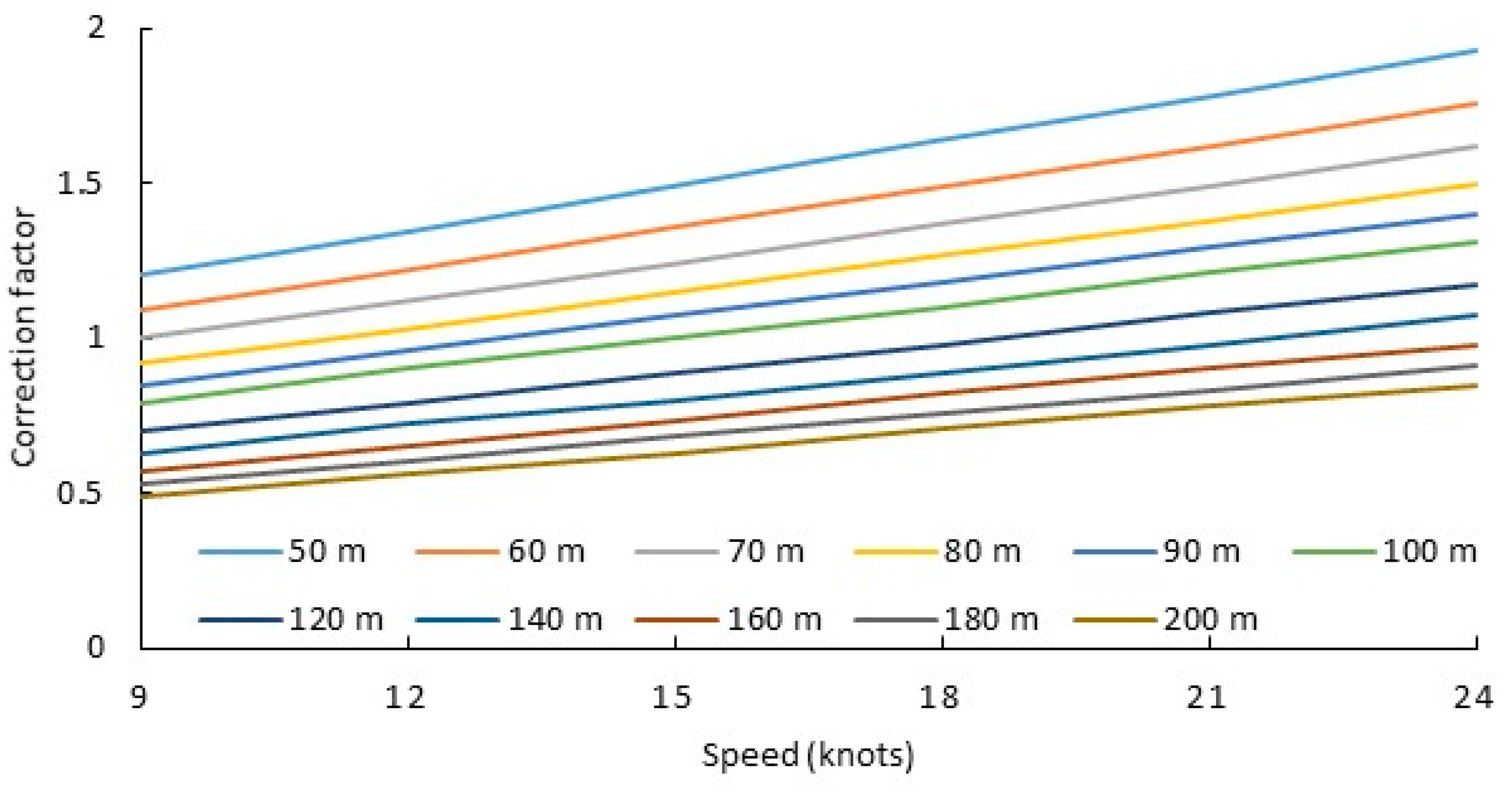
Figure 1. Correction factor for transverse acceleration by speed and ship’s length [8].
Jmse 11 01782 g001
Figure 2. Correction factor for transverse acceleration on ships where B/GM < 13 [8].
Jmse 11 01782 g002
Figure 3. Flow chart defining the novel mathematical model.
Jmse 11 01782 g003
Figure 4. Transverse acceleration data as per the CSS code and as per the DNG guidelines, where HD (high deck); MD (main deck); TD (tween deck); and LH (lower hold).
Jmse 11 01782 g004
Figure 5. Simulations of angular transverse accelerations for different headings and ship’s speeds during the first 60 s. (a) Vs = 0.0 knots and 000° < α < 090°; (b) Vs = 0.0 knots and 090° < α < 180°; (c) Vs = 5.0 knots and 000° < α < 090°; (d) Vs = 5.0 knots and 090° < α < 180°; (e) Vs = 10.0 knots and 000° < α < 090°; (f) Vs = 10.0 knots and 090° < α < 180°; (g) Vs = 15.0 knots and 000° < α < 090°; (h) Vs = 15.0 knots and 090° < α < 180°; (i) Vs = 20.0 knots and 000° < α < 090°; (j) Vs = 20.0 knots and 090° < α < 180°; (k) Vs = 22.0 knots and 000° < α < 090°; (l) Vs = 22.0 knots and 090° < α < 180°.
Jmse 11 01782 g005aJmse 11 01782 g005b
Figure 6. Simulations of rolling angles for different headings and ship’s speeds during the first 60 s for 090° < α < 180°. (a) Vs = 0.0 knots; (b) Vs = 5.0 knots; (c) Vs = 10.0 knots; (d) Vs = 15.0 knots; (e) Vs = 20.0 knots; (f) Vs = 22.0 knots.
Jmse 11 01782 g006
Figure 7. A 3D graph surface representing the roll angle and angular transverse acceleration at 15 knots. (a) α = 060° (b) α = 100°.
Jmse 11 01782 g007
Figure 8. Graphs for Vs = 15 knots, Td = 10 s, and Tw= 12 s during the first 60 s. (a) Transverse acceleration when 000° < α < 090°; (b) transverse acceleration when 090° < α < 180°; (c) rolling angles when 090° < α < 180°.
Jmse 11 01782 g008
Figure 9. Graphs for Vs = 15 knots, Td = 14 s, and Tw = 15 s during the first 60 s. (a) Transverse acceleration when 000° < α < 090°; (b) transverse acceleration when 090° < α < 180°; (c) rolling angles when 000° < α < 180°.
Jmse 11 01782 g009
Figure 10. Simulations of angular transverse acceleration for Vs = 15 knots and Td = 12 s during the first 60 s for different sea state conditions. (a) Tw = 9 s and 000° < α < 090°; (b) Tw = 9 and 090° < α < 180°; (c) Tw = 15 s and 000° < α < 090°; (d) Tw = 15 and 090° < α < 180°.
Jmse 11 01782 g010
Table 1. Ship’s particulars of general cargo ship under study.
VariableValue
Length (L)100 m
Beam (B)15.6 m
Depth cargo hold (Dep)9.0 m
Draught (d)6.0 m
Displacement (D)5500 Tm
KG4.0 m
GM1.1 m
Hatch cover coaming height2.0 m
Roll natural period (Td)12 s
Block coefficient (Cb)0.812
Bilge keelsNil
θ mean (initial)12°
Table 2. Non-percentage analysis of transverse acceleration (rad/s2) calculated according the different models for a constant ship’s stability (Td = 12 s) and θM = 12°.
Wave and Ship Parameters New Model CSSDNV
Tw (average)12 s0.05812 s0.0610.099
α angle (average)045°-
Vship (average)10 kt10 kt
Tw (low)6 s0.0716 s0.0680.099
α angle (average)045°-
Vship (average)10 kt10 kt
Tw (high)20 s0.05720 s0.0680.099
α angle (average)045°-
Vship (average)10 kt10 kt
Tw (average)12 s0.05712 s0.0610.099
α angle (high)080°-
Vship (average)10 kt10 kt
Tw (average)12 s0.05612 s0.0610.099
α angle (low)010°-
Vship (average)10 kt10 kt
Tw (average)12 s0.09412 s0.0840.099
α angle (average)045°-
Vship (high)20 kt20 kt
Tw (average)12 s0.05712 s0.0470.099
α angle (average)045°-
Vship (low)5 kt5 kt
Tw (high)20 s0.05720 s0.0680.099
α angle (low)010°-
Vship (average)10 kt10 kt
Tw (high)20 s0.05720 s0.0520.099
α angle (average)045°-
Vship (low)5 kt5 kt
Tw (low)6 s0.1076 s0.0680.099
α angle (high)080°-
Vship (average)10 kt10 kt
Tw (low)6 s0.0736 s0.0830.099
α angle (average)045°-
Vship (high)20 kt20 kt
Table 3. Studied waves’ characteristics.
Tw (s)Lw (m)Hw (m)
9124.764.15
15349.5011.64
Disclaimer/Publisher’s Note: The statements, opinions and data contained in all publications are solely those of the individual author(s) and contributor(s) and not of MDPI and/or the editor(s). MDPI and/or the editor(s) disclaim responsibility for any injury to people or property resulting from any ideas, methods, instructions or products referred to in the content.