Review

State-of-the-Art Review and Future Perspectives on Maneuvering Modeling for Automatic Ship Berthing

1
State Key Laboratory of Maritime Technology and Safety, Wuhan University of Technology, Wuhan 430063, China
2
School of Transportation and Logistics Engineering, Wuhan University of Technology, Wuhan 430063, China
3
Intelligent Transportation Systems Research Center, Wuhan University of Technology, Wuhan 430063, China
4
National Engineering Research Center for Water Transport Safety, Wuhan 430063, China
5
School of Navigation, Wuhan University of Technology, Wuhan 430063, China
*
Author to whom correspondence should be addressed.
J. Mar. Sci. Eng. 2023, 11(9), 1824; https://doi.org/10.3390/jmse11091824
Submission received: 18 August 2023 / Revised: 14 September 2023 / Accepted: 16 September 2023 / Published: 19 September 2023

Abstract

:
Automatic berthing is at the top level of ship autonomy; it is unwise and hasty to hand over the control initiative to the controller and the algorithm without the foundation of the maneuvering model. The berthing maneuver model predicts the ship responses to the steerage and external disturbances, and provides a foundation for the control algorithm. The modular MMG model is widely adopted in ship maneuverability studies. However, there are two ambiguous questions on berthing maneuver modeling: What are the similarities and differences between the conventional MMG maneuvering model and automatic berthing maneuvering model? How can an accurate automatic berthing maneuvering model be established? To answer these two questions, this paper firstly performs bibliometric analysis on automatic berthing, to discover the hot issues and emphasize the significance of maneuver modeling. It then demonstrates the similarities and differences between the conventional MMG maneuvering model and the automatic berthing maneuvering model. Furthermore, the berthing maneuver specifications and modeling procedures are explained in terms of the hydrodynamic forces on the hull, four-quadrant propulsion and steerage performances, external disturbances, and auxiliary devices. The conclusions of this work provide references for ship berthing mathematical modeling, auxiliary device utilization, berthing aid system improvement, and automatic berthing control studies.

1. Introduction

1.1. Background

According to statistics, 89%~96% of collision accidents [1] are caused by human error, and nearly 70% of accidents are related to the bad ship skills of the operators in the port [2]. To reduce or even eliminate the collisions caused by human errors, the maritime sector is moving rapidly towards autonomous shipping.
With the proposal of E-Navigation, the China Classification Society (CCS), Det Norske Veritas (DNV), Germanischer Lloyd (GL), Lloyd’s Register of Shipping (LR), and other authority institutions successively published corresponding regulations and standards on autonomous ships. Regarded as the last-mile issue in ship operation, the berthing maneuver is the most complicated and dangerous part of the mission, with comprehensive consideration of restricted and busy waterways, off-design ship performances, and strong external disturbances. In sum, automatic berthing is at the top level of autonomy [3,4,5].

1.2. Application of Automatic Berthing

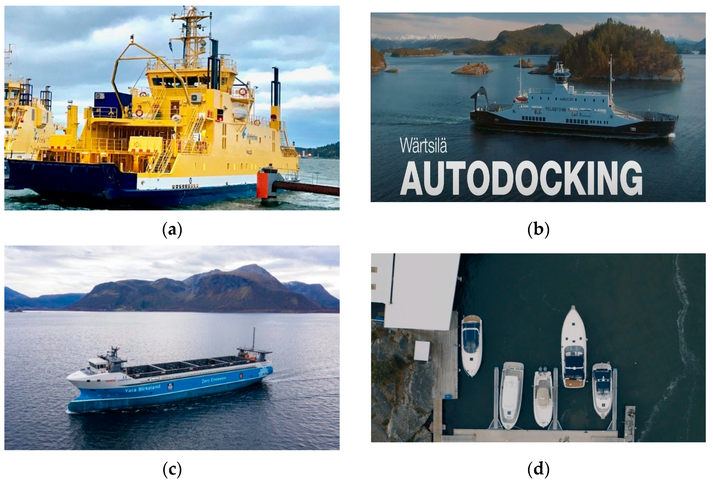
Shipping and technology institutions and enterprises in Asia and Europe have conducted automatic berthing studies and experiments and made remarkable progress; the applications of the automatic berthing systems are shown in Figure 1 and Figure 2. Between 2018 and 2019, Mitsui E&S Shipbuilding Co., Ltd. (MES-S) (Tokyo, Japan), Mitsui O.S.K. Lines, Ltd. (MOL) (Tokyo, Japan), Tokyo University of Marine Science and Technology (TUMST), Akishima Laboratories (Mitsui Zosen), and MOL Ferry conducted a total of 54 auto berthing operations using a virtual pier in open water, with the training ship ‘Shioji Maru’ [6]. And in 2022, the project team announced the success of an actual demonstration test of their jointly developed auto berthing and un-berthing system, equipped on the large-sized car ferry ‘Sunflower Shiretoko’ [7]. In 2022, MOL (Mitsui O.S.K. Lines, Ltd.) completed the world’s first containership sea trial for unmanned docking and undocking, with a 1870 DWT containership ‘Mikage’ [8]. In 2020, KASS (Korea Autonomous Surface Ship) Project [9] brought together KRISO, KAIST, Korea Maritime and Ocean University, and other institutions, to investigate autonomous ships and to release the study objective on berthing aid systems and automatic berthing prototypes. In China, Navigation Brilliance performed a series of autonomous ship tests, with the application of a berthing control system on a training ship ‘ZhiTeng’ [10], and achieved assisted berthing and automatic berthing on a 117 m 300 TEU container ship ‘ZhiFei’ [11].
In 2018, Rolls-Royce and Wartsilia successively announced their achievement with the automatic berthing control system. Rolls-Royce and the Finnish state-owned ferry operator Finferries [12] successfully demonstrated automatic berthing with a developed autonomous navigation system, without any intervention from the crew, with a fully autonomous 53.8 m double-ended car ferry ‘Falco’. Wartsilia [13] successfully carried out a world-first autodocking test on an 83m-long ferry ‘Folgefonn’. The test covers the full ship docking procedure, performs a gradual slowing of speed, and activates the line-up and docking maneuver fully automatically until the ship is secured at the berth. In 2021, Kongsberg and Yara [14] used the world’s first fully electric and autonomous container ship ‘YARA Birkeland’, an 80 m 120TEU open-top container ship, preliminarily achieving automatic berthing with the assistance of a Macgregor intelligent mooring system. In the same year, Volvo Penta [15] released their assisted docking system for boat docking, to remove the dynamics of wind and current and to improve the control for maneuvering in tight spaces: this is the first commercial application of an integrated berthing assistant system. An overview of the automatic berthing applications is presented in Table 1.

1.3. Contributions

The berthing maneuver in the harbor area is one of the key problems of ship manipulation, as the course stability and helm response of the ship is rather different from that in open-water conditions. This paper aims to explore the hot issues in automatic berthing maneuver modeling, demonstrate the similarities and differences of the conventional maneuvering modeling group (MMG) [16] model and the berthing maneuver MMG model, and emphasize the significance of berthing maneuver modeling. The main contributions of this paper are as follows:
(1)
Conducts bibliometric and statistical analysis on existing automatic berthing research, and extracts the hot issues of automatic berthing.
(2)
Demonstrates the similarities and differences between the conventional MMG model and berthing maneuver MMG model.
(3)
Summarizes the motion specifications and hydrodynamic performances of the berthing maneuver, and provides proper mathematical expressions.

1.4. Outline

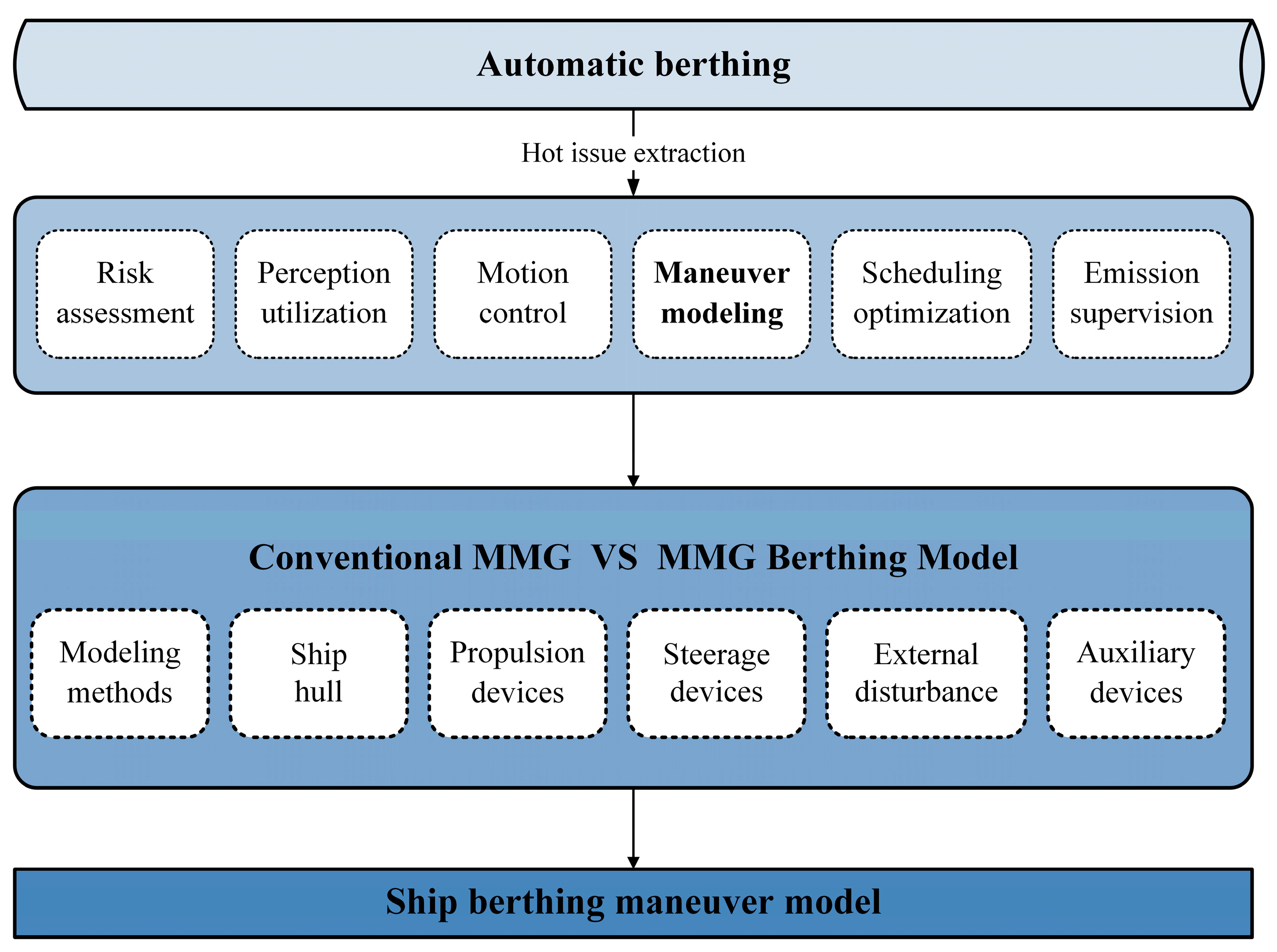
The outline of this paper is organized as follows: Section 1 introduces the technical background and application status of automatic berthing, illustrating the contributions and outline of the present paper. Section 2 performs bibliometric analysis on automatic berthing, generalizes six main topics of automatic berthing study, and indicates the similarities and differences of the conventional MMG model and the berthing maneuver MMG model. Section 3 introduces the advantages and disadvantages of three common mathematical modeling methods, and provides suggestions on the utilization of the berthing maneuver modeling method. Section 4 concludes with four motion specifications and hydrodynamic characteristics, and gives a specific mathematical modeling procedure. Conclusions and perspectives on berthing maneuver modeling are provided in Section 5. The workflow of this paper is illustrated in Figure 3.

2. Bibliometric Analysis

Scientometric analysis [17,18] presents high-level insights into the research domain; the field tendencies, important issues, study contents and methods can be readily visualized, conveniently identified and interpreted. In this section, bibliometric analysis is conducted to show the timeline and source distribution of automatic ship berthing within the collected literature database. A global correlation analysis and research focus of each study subject are discussed via research density in the following subsections.

2.1. Literature Search and Visualization

In the present work, the reference and citation database Web of Science (WoS), and bibliometric software VOS-viewer are adopted to collect references, and analyze the important issues and correlation of current references related to automatic berthing. The method and process of a literature index [19] and visualization are as follows:
(1)
The first step is to search the literature in the WoS database and the KCI-Korean journal database, with the following index keywords in the theme, abstract, and keywords: (“berthing*” OR “docking*”) AND (“ASV” OR “unmanned surface vessel” OR “unmanned surface vehicle” OR “autonomous surface vessel” OR “autonomous surface vehicle” OR “ship”) NOT (“underwater” OR “ROV” OR “UUV” OR “AUV” OR “aircraft” OR “drone” OR “car” OR “truck” OR “launch” OR “recovery” OR “cell” OR “actuator”);
(2)
The second step is to go through the collected literature and remove the research that is out of this work’s scope; 115 papers are retained;
(3)
The third step is to supplement studies and papers that are the source of certain research or cited in the selected papers but not included in the database; finally, 134 papers are added. With the literature collection and filter, a total of 249 articles consistent with the research scope are collected.
(4)
The fourth step is to extract the research objects, methods, contents, and publication time from the titles, abstracts, and keyword section of the collected references, and establish a bibliometric database.
(5)
The fifth step is to set up the threshold for the occurrence number in the extraction database, and then plot the network illustration on automatic berthing studies and density diagrams of the detailed research methods and techniques.

2.2. Global Analysis

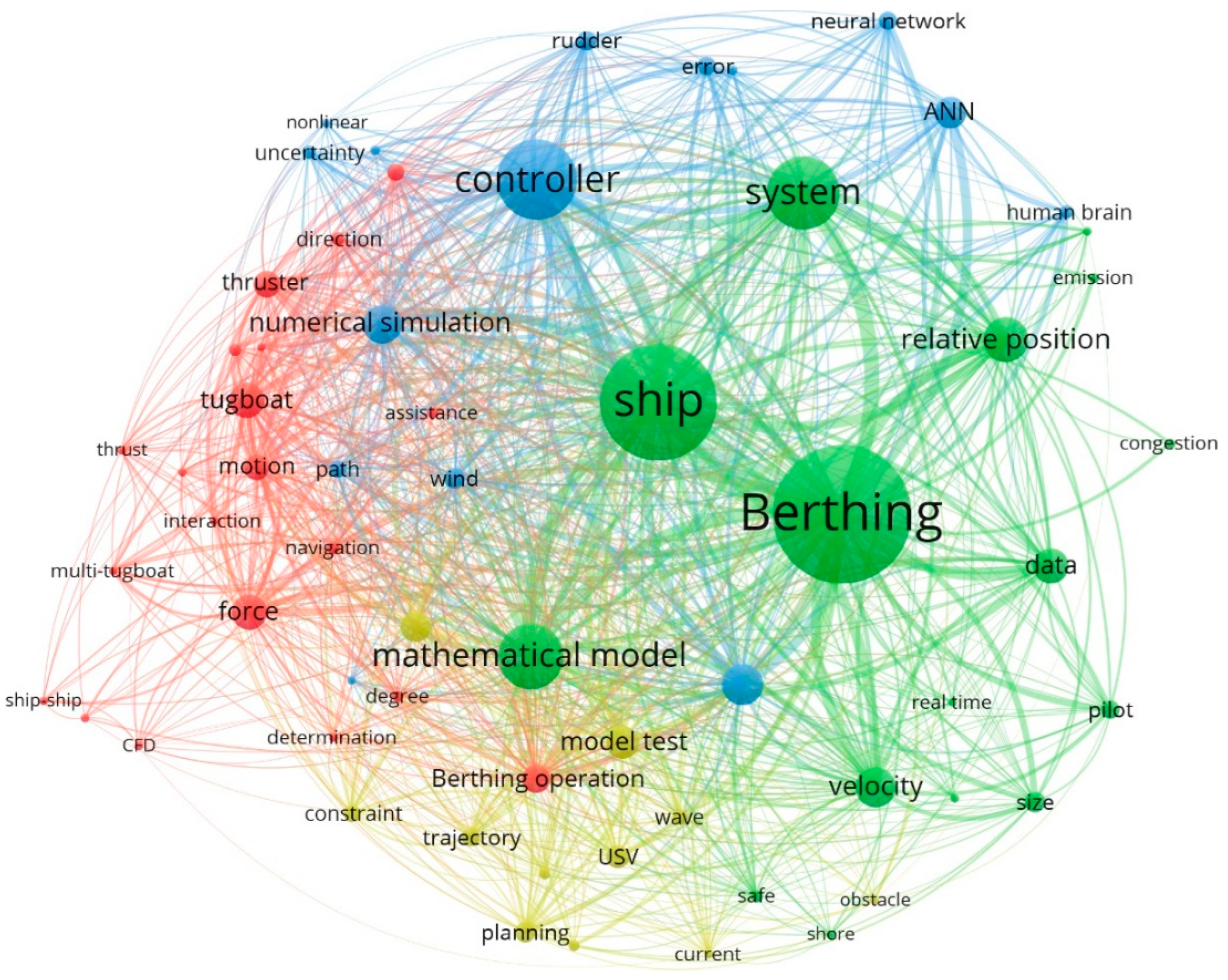
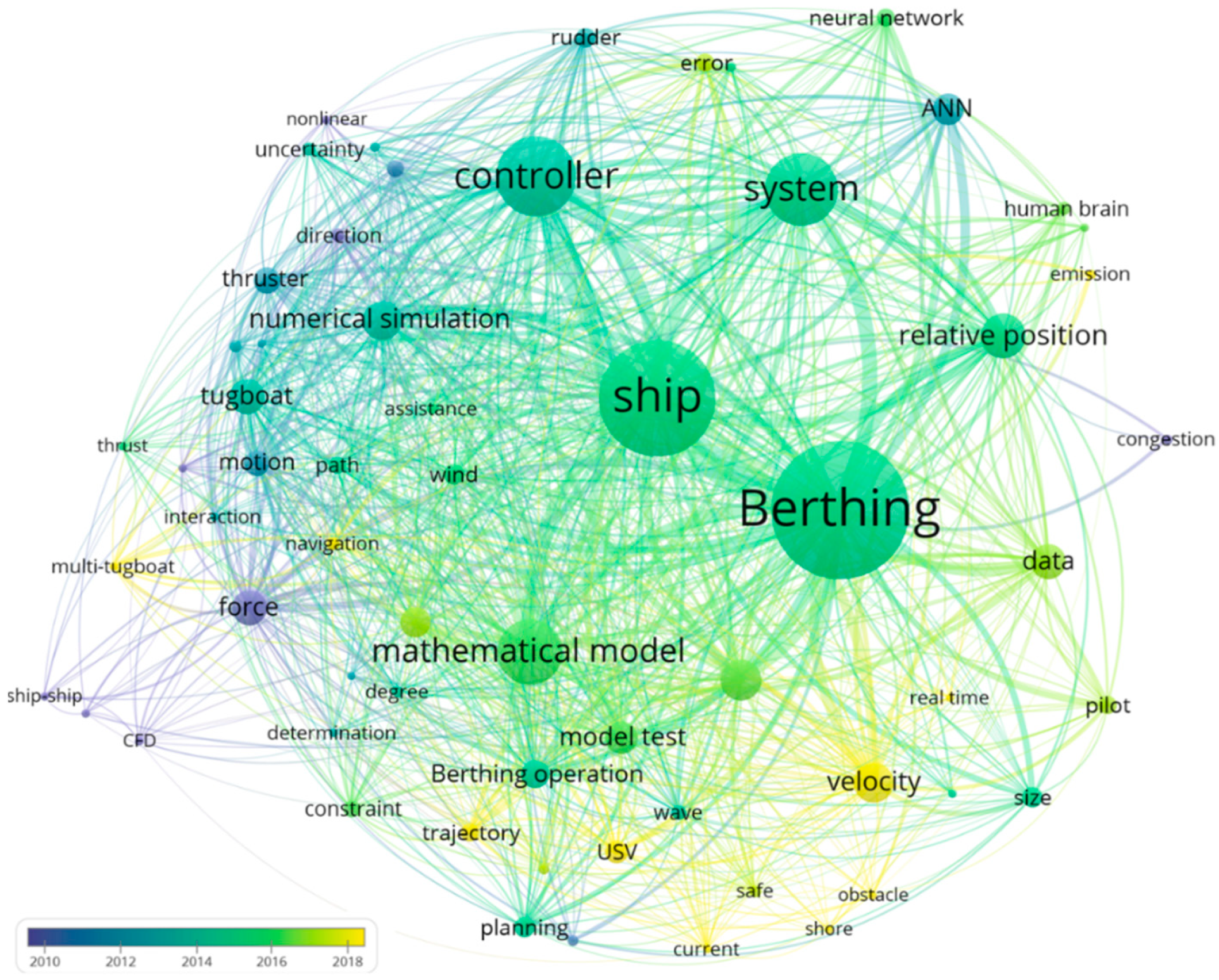
The overall research objective dependency statistic and timeline distribution on the automatic berthing study are illustrated in Figure 4 and Figure 5. The global network contains four highly correlated clusters, where the red band relates to the Berthing Maneuver, the blue group is associated with Control Method, and the collections of green and yellow knots are in connection with Mathematical Modeling and Safety Factors, respectively. To some extent, the four aspects with strong relevance indicate that the docking operation itself is a complicated maneuvering procedure and that the study of automatic berthing is not isolated, but correlated with other research interests, such as study constraints or objectives.
In the database of this work, the earliest study [20] on automatic berthing could date back to the late 1980s, followed by the work of Kouichi Shouji [21] and Hiroyuki Yamato [22]. As Takeo Koyama stated, the automatic berthing system is a knowledge-based system, involving the production rules that are mostly acquired from the shipmasters, pilots, and circumstance-dependent parameters. The subsequent works on automatic berthing adopt the knowledge-based or expert-based framework as the study constraints.
Systematic studies on automatic berthing started in the 2000s, focusing on the hydrodynamic forces and ship motions in the berthing procedure. Then the control method and system came into sight, followed by neural network and other intelligence algorithms, and the low-speed low-frequency, and high-accuracy berthing control problem were realized upon the simulation level. As test methods and measurement accuracy improved by leaps and bounds, the maneuverability model on ship docking was introduced to describe the non-linear ship motion responses and mechanism and to elevate the ship motion control effectiveness. Up until now, multi-factor (trajectory, external disturbance, maneuvering velocity error, and emission, etc.)-coupled motion control on self-berthing and multi-tug assistant berthing have been important issues, among which pilot, navigation, and trajectory refer to the berthing plan, and velocity corresponds to the approaching angle and velocity in the berthing maneuver. In addition, with the development of learning and identification algorithms and data processing, the clusters of data are found to play an important role in motion control and statistical analysis study.

2.3. Correlation Analysis

In conclusion, the study keywords of automatic berthing are Risk Assessment, Scheduling Optimization, Emission Supervision, Perception Utilization, Motion Control, and Maneuverability Modeling. Scheduling optimization [23] and emission supervision are studied to relieve the pressure on traffic flow, improve the operation efficiency of the harbor area, and reduce air pollution. However, these two aspects make little contribution to the automatic berthing technology, and hence are not discussed here. Detailed statistical analyses of the other branches are conducted in the following parts.

2.3.1. Risk Assessment, Perception Utilization and Motion Control

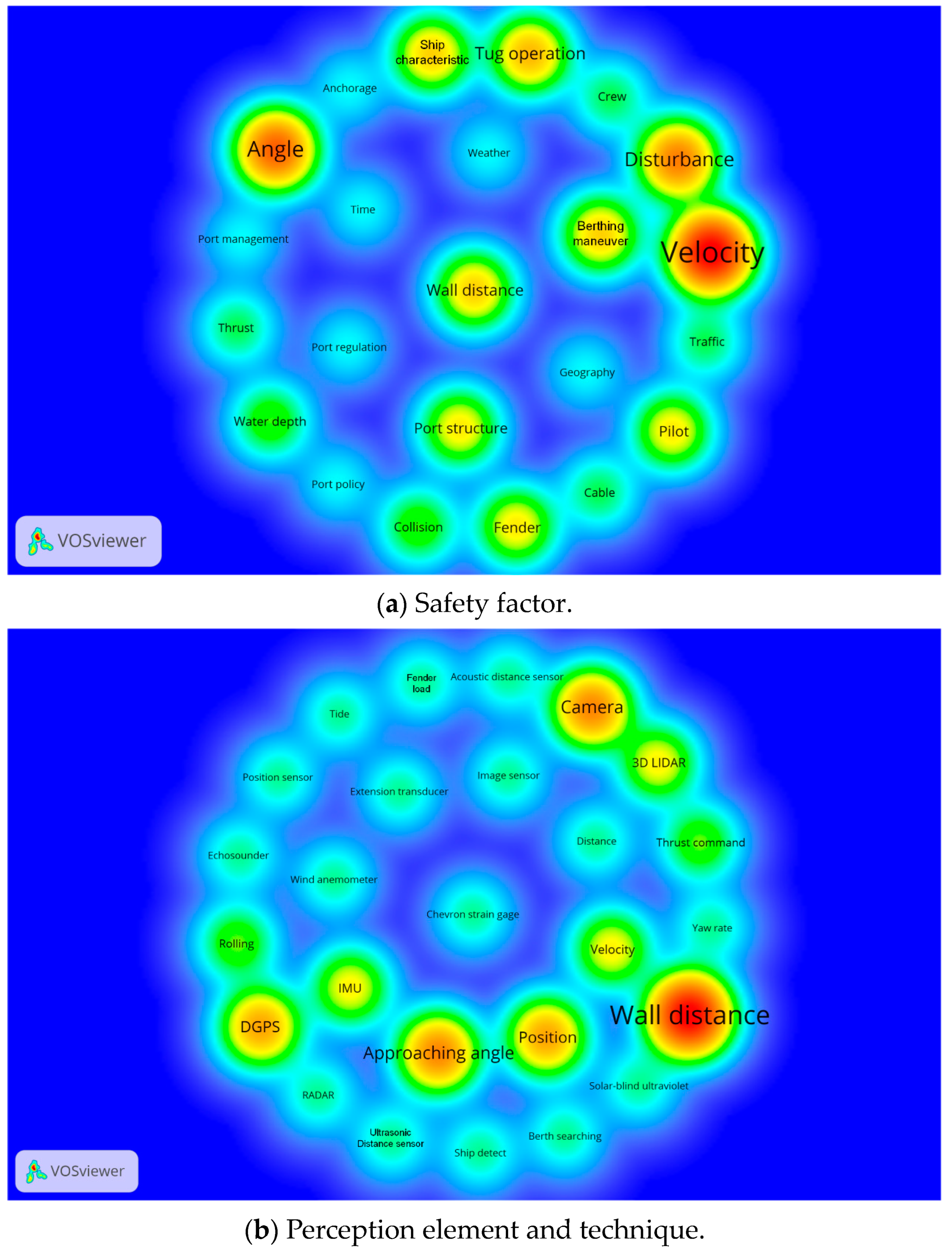
Risk assessment extracts the manipulating principles and concerns of berthing operation, and quantifies the automatic control indices; it is the insurance for automatic berthing. As illustrated in Figure 6a, the safety factor could be categorized by order of importance into ‘ship skills’, ‘quay layouts’, ‘external disturbances’, ‘ship characteristics’, ‘traffic flow’, and ‘port regulation’. Each aspect is interrelated and constrained. Ship skills, wall distance, approaching angle, and lateral speed, are essential to determine the ship’s safety berthing principles [24,25], which are affected by ship actuation level and external disturbances [26]. As for under-actuated ships, traditional large ships, or unexpected weather conditions, generally it is suggested or required that the ship berth with the assistance of tugs. Moreover, the quay layouts of water depth, berth orientation, and position could also hold up the berthing process.
Perception utilization acts as a pilot in automatic berthing, supports berthing strategy elaboration, environmental and state perception, and is the extra eye [27] and premise of automatic berthing. As illustrated in Figure 6b, the perception element and acquisition methods could be categorized by order of importance into ‘berth and obstacle perception’, ‘orientation and position perception’, ‘own-ship state perception’, ‘environmental perception’, and ‘target-ship perception’. Each aspect is indispensable. In correspondence with safety berthing principles, approaching angle, lateral speed, and wall distance are the most significant indices. Among these, the approaching angle, lateral speed, and other own-ship states are monitored through DGPS (Differential Global Positioning System) and IMU (inertial measurement unit), the berth and bollard location and target-ship detection are determined by the camera [28], millimeter wave RADAR [29], and other position sensors, while in severe weather conditions 3D LIDAR [30], ultrasonic sensor, solar-blind ultraviolet and other measurement gages are employed to make up the deficiencies.
According to statistics, 70% of accidents are related to the bad ship skills of the drivers in the port [2,31], and thus ship motion control is of vital importance to the berthing operation. In the traditional berthing process, ship control is a complicated system with multi-input sources and multi-output terminals. It requires the officers in charge to collect and resolve massive data expressing the external conditions and own-ship states, the shipmaster and pilot to make up a berthing plan and alternative plan, and the chief officer and chief engineer to convert and supervise the instruction execution conditions of the shipmaster.
The automatic berthing process [32] is described as the following: move the ship with low speed from pose A in the proximity of the harbor to pose B lying right next to it, while simultaneously avoiding all static and dynamic obstacles. The hidden scientific control problems are to position the target ship to the final pose B with real-time feedback of the perception elements (wall distance, lateral speed, and approaching angle) in the restricted water area and with strong environmental disturbances [33]. In the berthing process, path planning [34,35], trajectory tracking [36,37], stabilization and robustness control are essential control targets. Furthermore, with regard to multi-tug-assistance berthing control, it is necessary to exert constant control on the thrust allocation induced by the assistant tugboats, and to monitor the status of the target ship [38,39,40]. Whether for the self-berthing or tug-assisted berthing, wall distance, approaching angle, ship speed, and yaw rate are the control indices. Accordingly, ship berthing control is a low-speed low-frequency, and high-accuracy berthing control problem.
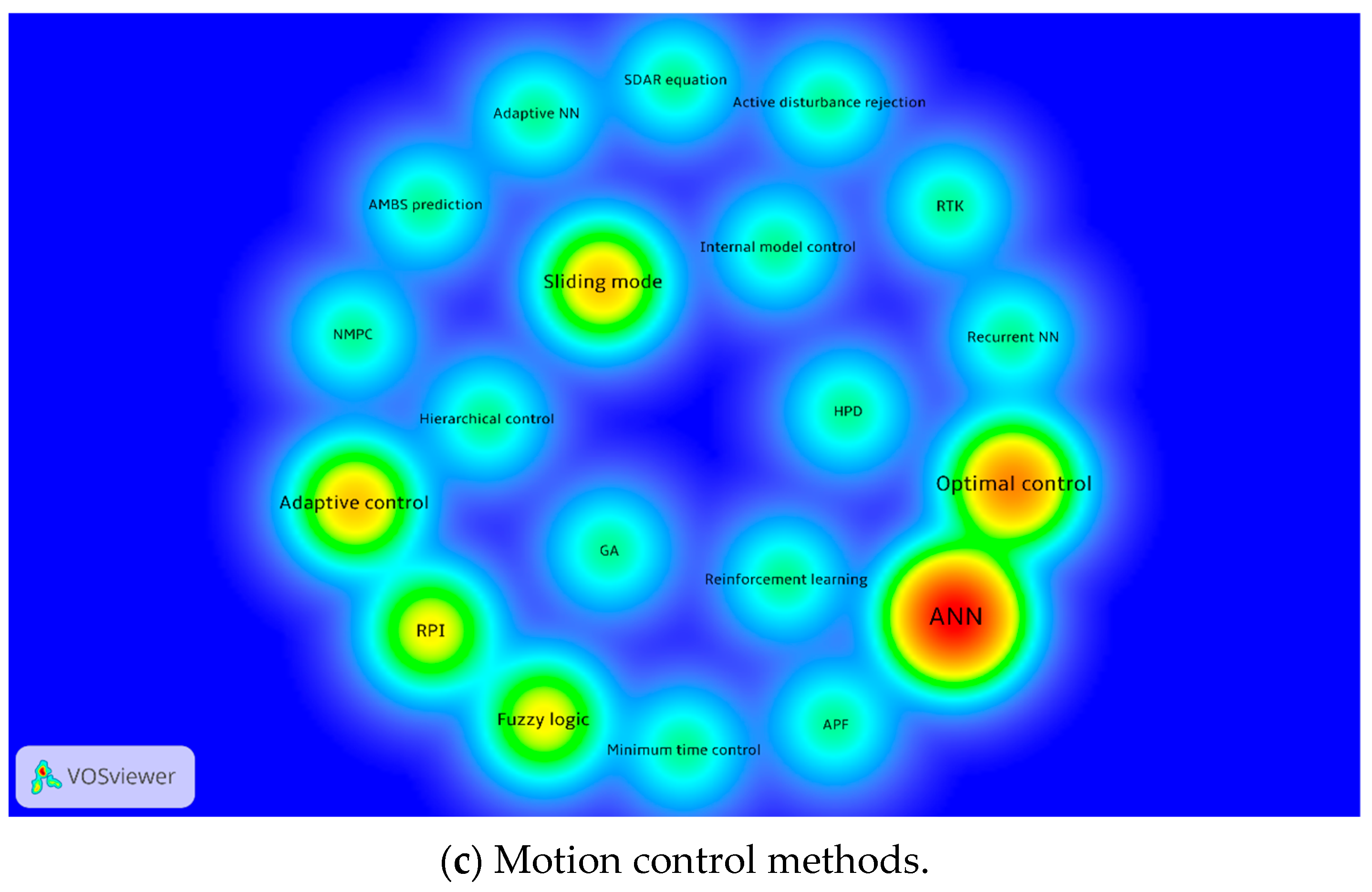
The density of motion control methods is illustrated in Figure 6c: model predictive control [41], fuzzy logic control [42], adaptive control [43], sliding mode control [44], optimal control [45], and artificial neural network-based control [46,47] are the most common and proven control technologies. Most of the above control methods are only effective on a specified scene, and once the external conditions change the parameters of the control system are ineffective. To resolve such deficiencies, artificial neural networks and other learning algorithms [48,49] are adopted. However, the learning algorithms and intelligent algorithms are fed on massive data, which represents a high cost; moreover, once the imported berthing condition is not involved in the training database, the system makes incorrect decisions, even breaking down. Furthermore, it is reported that most marine accidents are caused by ship–ship collision and ship–shore collision [50]. In order to reduce the risk of collision accidents, a collision avoidance algorithm [51] is embedded into the control system to determine and implement the required safety margin distance between the moored ships, moving ships, and the obstacles, which increases the system load to some extent. Thus, it is essential to improve the robustness of the control system.

2.3.2. Maneuverability Modeling

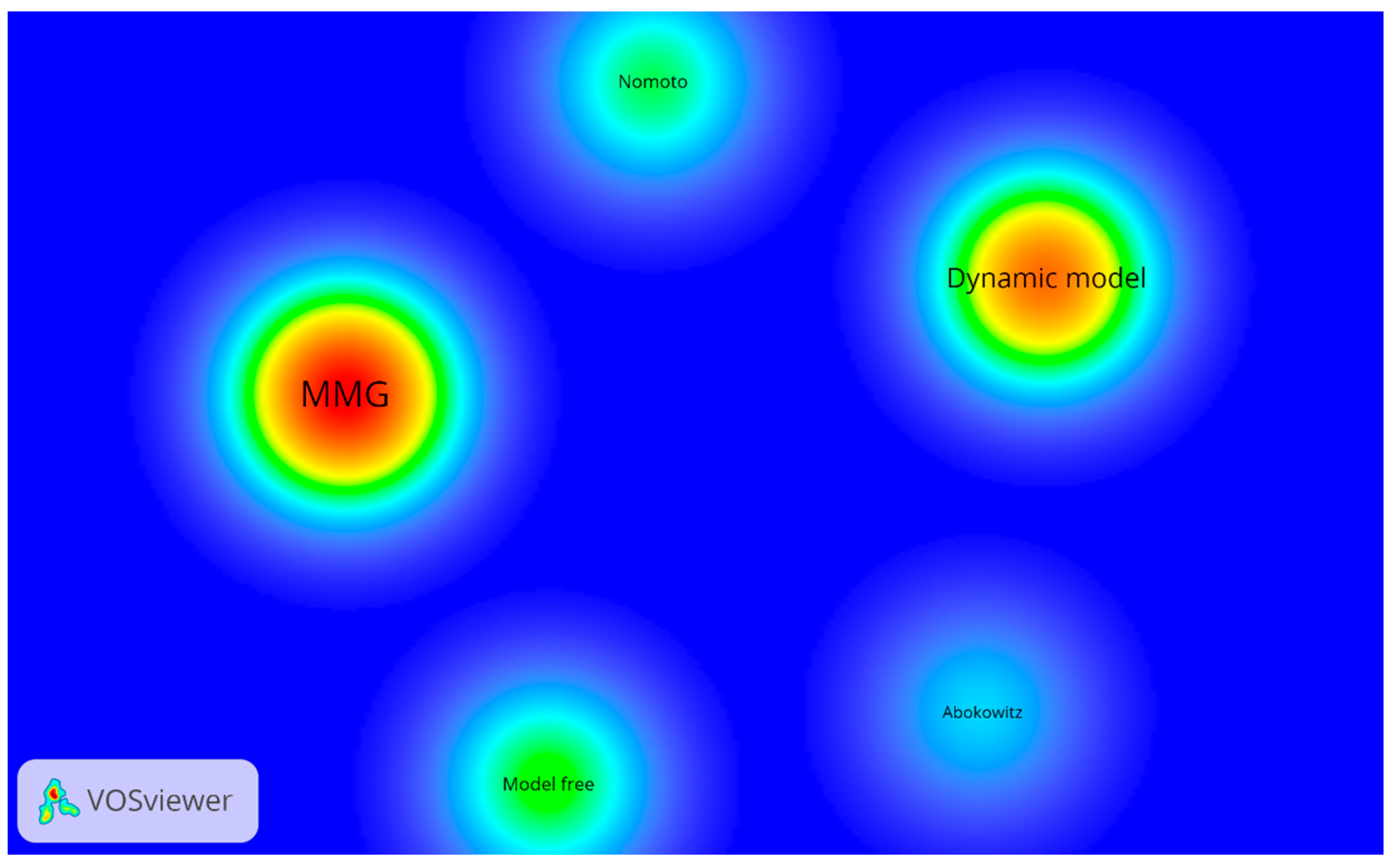
The ship maneuvering model is grounded in the mechanical characteristics, in order to denote ship responses under different internal and external inputs, and is the foundation of the automatic berthing control system. There exist two main effects and applications: one is to predict the maneuvering characteristics and help ship designers and operators know about the handling performance and the other is to provide a kinematic and dynamic foundation for the control system. As illustrated in Figure 7, the modeling methods could be categorized by intention into the ‘mechanism model’ and ‘control model’. The ‘mechanism model’ involves the Abkowitz model and MMG model. In the Abkowitz model [52], the ship is considered as a whole, and the hydrodynamic forces acting on the system are expressed as the function of ship motion, rudder steerage, and external disturbances, while the MMG model [16] treats the ship as an organism composed of a ship hull, propeller, rudder, bow thruster, wind, wave, and current. Additionally, auxiliary devices like tugs, cables, anchors, and waterway constraints like shallow-water effect, bank effect, and ship–ship interaction could also be represented in the MMG model. The ‘control model’ treats the ship as a multiple-input and multiple-output (MIMO) system, mainly containing the dynamic model, Nomoto model, and model-free model. The dynamic model [53] solves ship motion control issues with matrix formation obtained from the rigid-body kinetics. The Nomoto model [54], the so-called ship response model, is introduced to indicate the relationship between ship turning ability and rudder steerage, and is commonly adopted in automated rudder exploitation. And the model-free model [55,56] is a new form of resolving ship motion control in the black box model.
In the Abkowitz model, the ship hull, propeller, rudder and external disturbances are treated as a whole: the number of hydrodynamic derivatives exceeds 60, the physical meaning of some remains unclear, and it takes a lot more captive model tests to obtain the hydrodynamic derivatives. With regard to the dynamic model and the Nomoto model, the whole ship is considered as a MIMO control system. These methods are widely used in ship motion control; however, the hydrodynamic performance is eliminated to a certain extent. In comparison, the modular MMG model independently describes the hydrodynamic forces on the ship hull, propeller, thruster, rudder, and external conditions, with few interaction coefficients forging a bond with each other. Moreover, each coefficient has a distinct physical meaning, and could be obtained with fewer captive model tests.
In practice, small ships and actuated or over-actuated ships usually perform self-berthing. Large ships often berth with the assistance of tugs, and, when conditions permit, could also conduct independent berthing. Normally, the control actuators such as the propeller and rudder are designed for relatively high speed (design speed, economic speed, or constant speed). However, during the berthing process the ship undergoes much more complicated external conditions, such as extreme low speed, high drifting, propeller reversal, shallow-water effect, bank effect, and heavy traffic flow, which eventually lead to distinct changes in the hydrodynamic forces acting on the ship hull, propeller thrust, and rudder steerage force. It is of great practical significance to study the hydrodynamic and maneuvering characteristics of the berthing maneuver. Considering the model form, influencing factors, and manipulating features, the MMG model now is utilized in berthing maneuvering modeling, and will be discussed in detail in the following sections.

2.4. Discussion of MMG Model

Some studies [57,58,59,60,61] on ship berthing control adopt the conventional MMG mathematical model framework as the foundation of the control algorithm. In these research studies, a number of assumptions are proposed [16]:
Hydrodynamic forces acting on the ship are treated quasi-steadily.
The lateral velocity component is small compared with the longitudinal velocity component.
Automatic berthing control studies [62,63,64,65,66] considering the berthing maneuver characteristics have shown satisfactory results in comparison of model tests. In these research studies, the berthing maneuver specifications are discussed:
Hydrodynamic forces acting on the ship have strong non-linearity; the ship longitudinal velocity is small, and is of the same order as the lateral velocity and yaw moment.
Thrust and steerage forces have four-quadrant characteristics.
The ship is vulnerable to external disturbances.
Ship motion is assisted by auxiliary devices like side thrusters, tugs, cables, and anchors.
In sum, automatic berthing simulation results based on both methods are acceptable. However, there exist two ambiguous questions on the maneuver modeling framework for the berthing maneuver motion control:
(1)
What are the similarities and differences between the conventional MMG maneuvering model and the automatic berthing maneuvering model?
(2)
How can an accurate automatic berthing maneuvering model be established?
To answer the first question, the similarities and differences between the conventional MMG model and the berthing maneuver model are summarized in Table 2. With regard to the modeling methods, uniform methods (including the data-based method, system-based method, and CFD-based method) are adopted to obtain the ship hydrodynamic performances for both the conventional model and the berthing maneuver model. The main differences are found in the hull motion characteristics, propulsion and steerage device performances, external disturbances, and auxiliary devices. In the conventional MMG model a moderate speed is concerned, the hydrodynamic forces are treated as linear, and the should be smaller than 20 degrees; the resultant inflow angle to the thruster and drift-angle rudder is small, and the ship motion is relatively insensitive to the external disturbances. However, in the berthing maneuver process [67,68] the ship undergoes conditions like low advance speed, large drifting, four-quadrant thrust and low rudder effect, and the ship is vulnerable and sensitive to external disturbances.
In brief, there exist distinct differences between the conventional moderate speed MMG model and the berthing maneuver MMG model, and it is essential to build a proper and accurate maneuvering model for automatic ship berthing. The kind of effects the differences lead to and how to establish an accurate model will be answered in the following sections.

2.5. Remarks

Taken together, automatic berthing is a coordination of perception utilization, motion control, and mathematical modeling technologies. Perception is the premise, motion control is the key, and the maneuverability model is the foundation. A precise mathematical model is required to make clear ship responses to the internal operations and external disturbances. The modular MMG mathematical model is now widely adopted in the study of maneuver modeling, due to its accessible hydrodynamic forces, clear physical meaning, and explicit and flexible structure. In light of the maneuver specifications, a comparison between the traditional model and the berthing maneuver MMG model is performed, and the traditional MMG model is found to differ from the traditional model in the hydrodynamic forces on the hull, propulsion and steerage devices, external disturbances, and auxiliary devices. As for the automatic berthing, it is essential to establish a berthing maneuver mathematical model.

3. Berthing Modeling Methods

3.1. Mathematical Modeling Methods

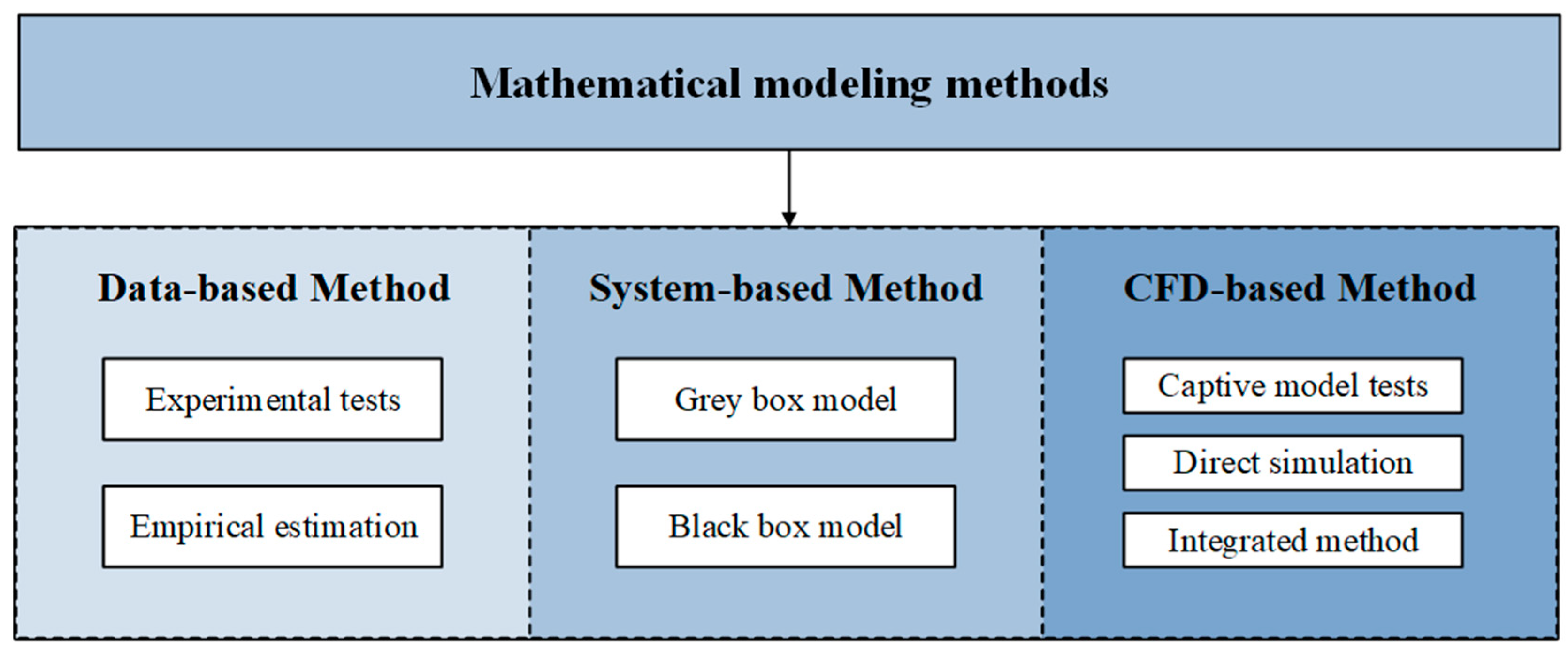
Grounded in the mechanical characteristics, the ship maneuvering mathematical model denotes ship responses under different internal and external inputs, and is the foundation of the automatic berthing control system. There exist two main functions, one being to assess and predict ship maneuverability, helping ship designers and operators to know about the handling performances, and the other to provide the kinematic and dynamic foundation for the control system. Based on the experience of the 25th ITTC maneuvering committee [69] and insights obtained from the SIMMAN 2008 workshop, the maneuvering prediction methods are organized into three main parts, the data-based method, the system-based method, and the CFD-based method. The overview of the maneuverability prediction methods is shown in Figure 8.

3.2. Data-Based Methods

The data-based method covers the experimental method and empirical method:
(1)
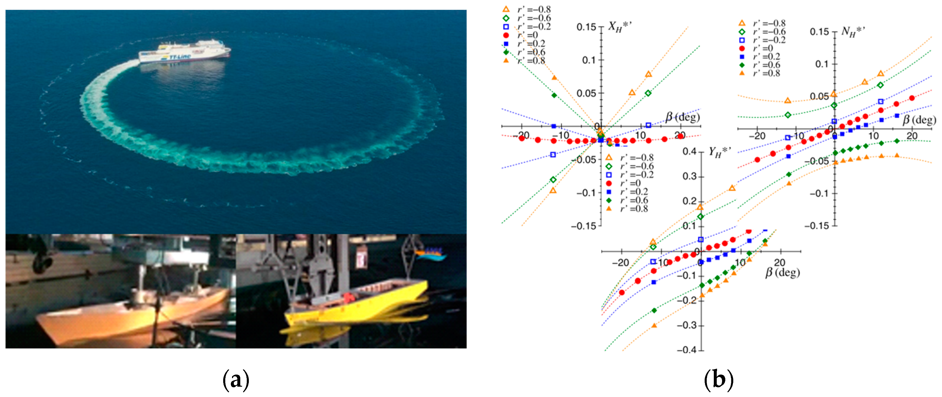
The experimental method mainly contains full/model-scale free-running tests, and captive model tests. The former method establishes a database involving the ship maneuverability indices of advance, transfer, overshoot, track reach, etc., to characterize the turning, yaw-checking, and stopping abilities, and to evaluate the ship’s inherent dynamic and course-keeping stabilities (shown in Figure 9a). Meanwhile, the captive model tests measure the hydrodynamic performance of ships to indicate the ship response under various external conditions.
(2)
The empirical method makes a quick estimation of the resistance [70] and hydrodynamic derivatives [71,72] of a target ship. This method conducts regression analysis on massive captive model test results of ships within a hull-type set; the hydrodynamic derivatives are expressed as functions of the ship’s main dimensions, and form parameters (shown in Figure 9b).
Figure 9. Data-based method. (a) Sea trails [73] and Model tests. (b) Regression analysis [16].
Jmse 11 01824 g009
The data-based method predicts the resistance and maneuverability of ships with flexibility. However, there exist some defects: the full-scale trails and model-scale tests normally come with a high cost; the database and the regression formulas rely heavily on the ship-type spectrum, and once the studied ship is not involved in the spectrum, or shows obvious differences in the hull profiles, this method cannot predict the maneuverability with certain precession. Additionally, the accuracy of this method is also influenced by scale effects.

3.3. System-Based Methods

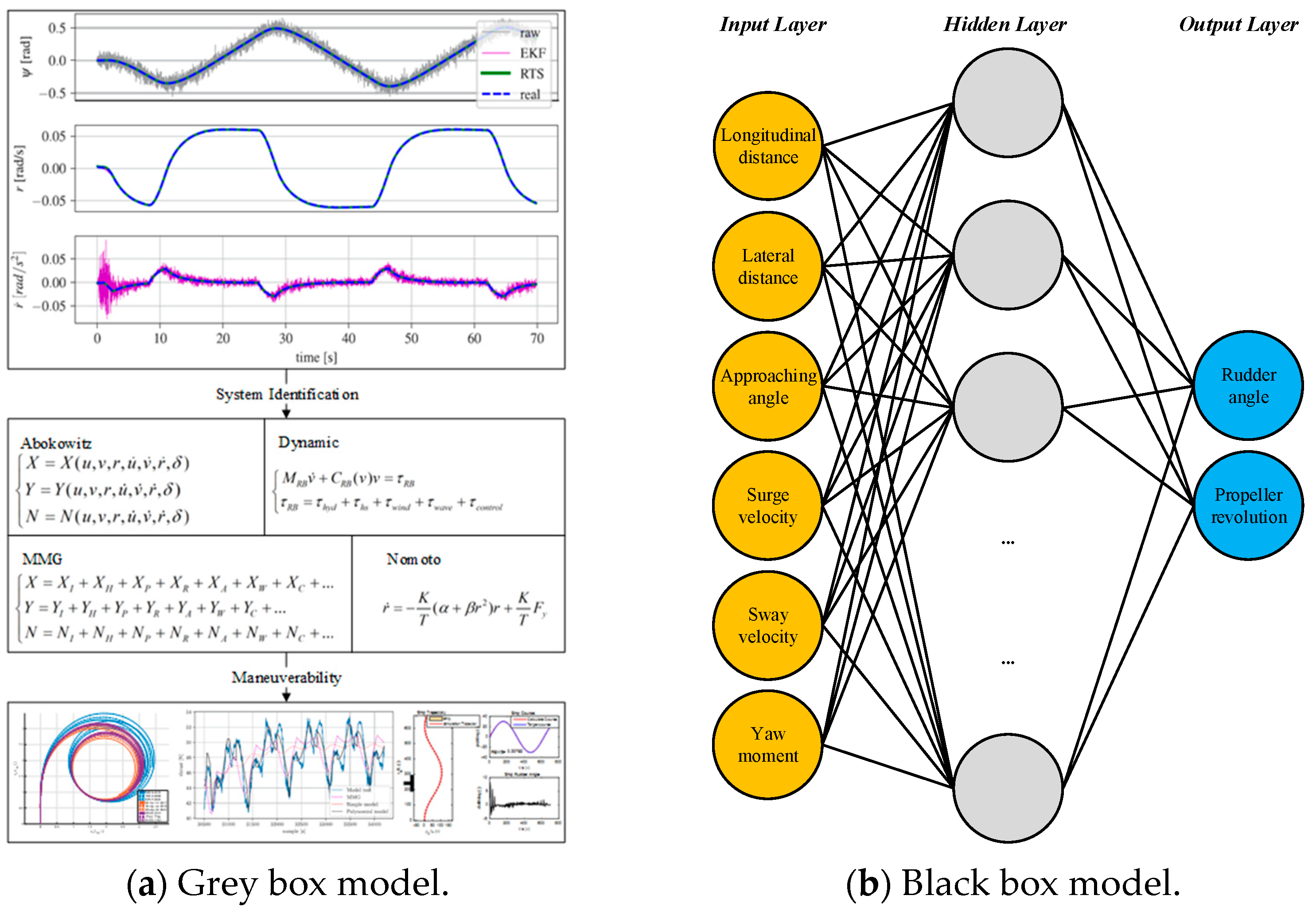
The system-based method, also known as the system identification (SI) method, mainly includes the grey box model and black box model. It is a control strategy that establishes a mathematical model equivalent to the measuring system based on the system’s input and output data [74]:
(1)
The grey box model sets a prior model structure [75]; some identification algorithms, such as maximum likelihood (ML) [76], Kalman filtering (KF) [77], the least squares method (LS) [78] or the improved algorithm are used to identify the experiment/simulation parameters like ship speed, yaw rate, propeller revolution, rudder angle, and trajectories. The maneuverability of the target ship is then obtained (shown in Figure 10a). However, these methods have some inherent disadvantages: the accuracy is sensitive to signal noise and initial estimations, and simultaneous drift is another critical issue.
(2)
To cope with these defects, the black box model is proposed. No prior information is needed other than the datasets to gain the mapping relationship between system input variables and output variables [79] (shown in Figure 10b). Machine learning and deep learning techniques have been successfully applied as tools to establish the identified model, for example, the least-squares support-vector machine (LS-SVM) [80], the fully connected neural network [81], the deep neural network [55,82], etc.
In general, the system identification method is a data-driven modeling method, utilizing the training data collected from simulation results, free-running model tests or full-scale trials. The accuracy is highly dependent on the training data, and the qualified and continuous-excitation input signal ensures better identification performance and generalization ability. However, once the training data are insufficient, or the excitation is weak, the accuracy and efficiency of identification reduces dramatically. Moreover, the specialty of the SI method in coping with the collected data indicates that this method could not predict the ship maneuverability at the design stage or in unknown conditions, but that it could improve the mechanical model accuracy. As for ship berthing maneuver modeling, an integrated SI-CFD method could be utilized to optimize the mechanical model accuracy and to provide a basis for the control algorithm.

3.4. CFD-Based Methods

The CFD-based method is the mapping of physical captive model tests and maneuvering model tests. The hydrodynamic forces are solved with the potential flow method or viscous flow method, and the method itself consists of virtual captive model tests, direct simulation, and the integrated method:
(1)
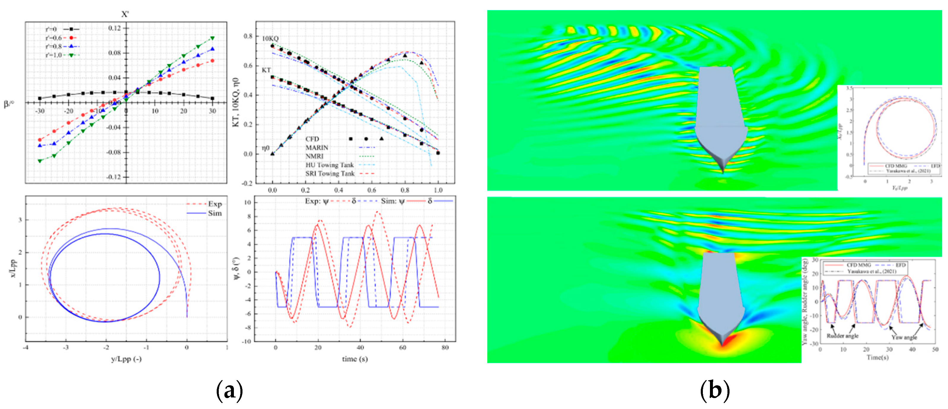
The virtual captive model tests method conducts specific maneuvering test simulations based on the maneuvering model [83,84] of the target ship, the hydrodynamic characteristics of which are obtained via the CFD method (shown in Figure 11a, where upper left is the dimensionless longitudinal force X’, upper right the propeller thrust coefficient KT, torque coefficient KQ, and thrust efficiency η0, lower left the comparisons of the turning maneuver trajectory, and lower right the comparisons of the heading angle ψ and rudder angle δ time histories). Moreover, the propeller–rudder interaction, ship–ship interaction, ship–bank interaction, shallow-water effects, and detailed ship amplitudes and flow field development could also be obtained. This is the most effective, economical, and widely used method for studying the maneuverability of a ship.
(2)
The direct simulation method indicates that the maneuvering model tests are performed with the CFD method directly (shown in Figure 11b, where the upper part is the turning maneuver, and lower part the zig-zag maneuver). This method can assess the maneuverability of a ship under various external conditions and working conditions (calm water, regular and irregular waves, constraint water, wind, propeller reversal, etc.), and observe the response of the target ship to rudder/propeller operations. However, this method demands longer research periods and stronger computing power, and it is not the best option for the maneuverability study at present.
(3)
In consideration of the research requirements, efficiency, and rapidity, a hybrid method that integrates the empirical method and CFD method is constructed, based on the study experience and solid foundation [85,86,87]. The hydrodynamic performances of the ship hull, propeller, and rudder are obtained from the CFD method, and the hull–propeller–rudder interaction factors are solved by empirical methods. The accuracy of this method is affected by the ship-type diversity involved in the empirical formula.
Figure 11. CFD-based methods. (a) Conventional CFD simulation [87]. (b) Direct CFD simulation [88].
Jmse 11 01824 g011

3.5. Remarks

The berthing maneuver modeling methods include data-based, system-based and CFD-base methods (shown in Table 3). Although the data-based methods are the true reflection of navigation practice, an enormous amount of time and money are injected into experiment design and data collection. The system-based methods are very much data-dependent; however, in the berthing process, the ship hydrodynamic forces, propeller thrust, and rudder steerage force are strongly non-linear and vulnerable to external disturbances, so that it is hard to obtain valid data. Moreover, the physical meaning is unclear and the model structure is unknown in the black box model. The CFD method could intentionally control and change the study circumstances and the output hydrodynamic forces with acceptable accuracy. Hence, the CFD-based method could be used to establish the berthing maneuvering model. Under certain circumstances, a hybrid method integrates the empirical method, and the CFD method is introduced to further improve the calculation efficiency.

4. Berthing Maneuver Modeling

In the berthing process, ship motion is determined by the hydrodynamic forces acting on the ship hull, thrust force induced by the propeller and thruster, steerage force generated by the rudder, external forces like water-cushion effects, wind, and current, and additional forces provided by auxiliary devices like the side thruster, tugs, and cables. In conclusion, the forces could be classified into four hydrodynamic features, within which the most important factors are as follows:
(1)
Low-speed effect, large drifting and yaw rate. Compared with the service speed, in the berthing process the longitudinal velocity is very low, the lateral speed and yaw rate are of the same magnitude, the hydrodynamic forces and moments acting on the ship hull present strong non-linearity, and the ship motion covers the full drifting conditions.
(2)
Four-quadrant propulsion and steerage. Ships in berthing operation need to operate the main engine frequently to adjust the ship amplitude and maintain the rudder steerage. Under such circumstances, the propeller and rudder work in four-quadrant conditions, and their performances are explicitly different from the designed capabilities.
(3)
External disturbances. Under berthing maneuver, thrust due to the propeller cannot counteract the disturbances induced by external environments. To maintain the steerage of the ship, the external disturbances, including the water-cushion effect (shallow-water effect, bank effect, ship–ship interaction), wind, and current, should be considered.
(4)
Auxiliary-device-induced forces. Due to the small velocity and low propeller revolution, the rudder is affected by the wake, and the crabbing motion and turning motion of the ship usually count on the assistance of auxiliary devices like side thrusters, tugs, and anchors.

4.1. Hydrodynamic Forces Acting on the Hull

4.1.1. Ship Speed

In accordance with the ship maneuvering velocity, surface ship motions could be divided into three categories: low-speed motion, moderate-speed motion, and high-speed motion [89]. In consideration of ship safety, marine structure safety, and personnel safety, whether in the wharf design guidelines, or the measured actual operation, the berthing ships are asked to impact with the dock at a low or extremely low speed and with a parallel attitude. Namely, the ship berthing maneuver is a typical variable-speed period, ranging from service speed to low speed, and covering harbor entry to ship docking.
Apart for the speed variation, there exist multiple factors affecting the ship’s maneuverability in the berthing process. For instance, ship dimension and displacement determine the difficulty of changing/maintaining kinetic states; restricting waters would raise the squat effect, bank effect, and bank-cushion effect; winds and tidal currents could lead to drifting and shifting of a ship; and under the assistance of tugs, ship maneuverability could be greatly improved. To better understand the motion response of ships under different steerage and internal and external conditions, it is important to perform further studies to reveal the hydrodynamic mechanism and to characterize the maneuvering indices.

4.1.2. Drifting and Rotation Rate

In the berthing process, ships undergo larger drifting (|β| = [0, 180°]) and greater turning angular velocity (|r’| > 0.6); the ship longitudinal velocity component is of the same dimension as the lateral component velocity and yaw rate, or even far smaller. Thus, concerns about the hydrodynamic forces move from the friction-dominant longitudinal force to the pressure-dominant lateral force and yaw moment. Under such states, the hydrodynamic forces present strong non-linearity, and the traditional linear mathematical model cannot describe the hydrodynamic forces and moments accurately.
Within the framework of the modular mathematical model, three resolutions are introduced to express the hydrodynamic forces acting on the ship hull:
(1)
The piecewise model [89] involving the small drifting model, moderate drifting model, and large drifting model. It should be noted that the moderate drifting model is the interpolation of the small drifting model and the large drifting model.
(2)
The unified model [68,90], based on the cross-flow drag theory, to express the ocean and harbor-area maneuvering.
(3)
The table model [91,92], with direct application of the hydrodynamic forces.
The small-drift-angle model [93] is expressed as:
{ X H = R 0 + X v v v 2 + X v r v r + X r r r 2 Y H = Y v v + Y r r + Y | v | v | v | v + Y | v | r | v | r + Y | r | r | r | r N H = N v v + N r r + N | v | v | v | v + N v v r v 2 r + N v r r v r 2 ,
where XH and YH are the hydrodynamic forces, and NH is the hydrodynamic moment acting on the ship hull, R0 is the resistance under the straight moving condition, v the lateral component of ship velocity, r the yaw rate, and Xvv, Yr, Nvvr, et al. the hydrodynamic derivatives.
Based on cross-flow drag theory, the large-drift-angle model [94] is expressed as:
{ X H = X H ( r = 0 ) + X v r v r + X r r r 2 Y H = Y H ( r = 0 ) + Y r | u | r + 1 2 ρ d C d { L v | v | L / 2 L / 2 | v + C r Y x r | ( v + C r Y x r ) d x } N H = N H ( r = 0 ) + N r | u | r 1 2 ρ L d C d { L v | v | L / 2 L / 2 | v + C r N x r | ( v + C r N x r ) x d x } ,
where XH(r = 0), YH(r = 0), NH(r = 0) represent the hydrodynamic derivatives related to the lateral speed, u is the longitudinal speed, v the lateral speed, r the yaw rate, Cd the cross-flow resistance coefficient with drift angle β = 90°, CrY and CrN the correction factor, L the ship length, d the ship draft, and x the longitudinal distance from the mid-ship point.
Based on cross-flow drag theory, the unified model [68] is defined as:
{ X H = 1 2 ρ L d { [ X 0 ( F ) + ( X 0 ( A ) X 0 ( F ) ) ( | β | / π ) ] u U + ( ( m y + X v r ) L v r ) } Y H = 1 2 ρ L d [ Y v v | u | + ( Y r m x ) L r u ( C d L ) L / 2 L / 2 | v + C r Y x r | ( v + C r Y x r ) d x ] N H = 1 2 ρ L 2 d [ N v v u + N r L r | u | ( C d L 2 ) L / 2 L / 2 | v + C r N x r | ( v + C r N x r ) x d x ] ,
where X0(F) and X0(A) are the straight forward and astern resistance coefficients, and mx and my are the added masses of x and y axis directions, respectively.
And the table model [91] is defined as:
{ X H = 1 2 ρ L d { [ U 2 + ( L r ) 2 ] C H X ( β , α r ) U 2 R 0 cos β } Y H = 1 2 ρ L d [ U 2 + ( L r ) 2 ] C H Y ( β , α r ) N H = 1 2 ρ L 2 d [ U 2 + ( L r ) 2 ] C H N ( β , α r ) ,
CHX, CHY, and CHN are the hydrodynamic force coefficients represented as functions of the ship drift angle β and the yaw rate angle αr, β = tan−1(-v/u), αr = tan−1(rL/U). The hydrodynamic forces XH, YH and NH are non-dimensionalized by 0.5ρLd[U2 + (Lr)2] and 0.5ρL2d[U2 + (Lr)2].

4.2. Propulsion and Steerage Devices

The propeller and rudder are the key elements in ship maneuvering [95]. In the berthing process, the main engine and rudder are frequently operated to achieve the turning, braking, and reversing of the ship. Under such operations, the propeller and rudder work with off-design conditions. With respect to the safety and efficiency concerns of ship docking/undocking, it is important to fully understand the performances of the propeller and rudder. The off-design performance refers to the propeller and rudder characteristics under the following telegraph conditions: ahead ship ahead, ahead ship astern, astern ship astern, and astern ship ahead. The four-quadrant performance is implied by the relationship between thrust and inflow angle (KT-βp), or the thrust and propeller hydrodynamic pitch angle (KT-θp); the diagrams of the four-quadrant propulsion and steerage are summarized in Figure 12, and the correspondence of ship velocity U and propeller resolution np is shown in Table 4:
At present, the modeling of the four-quadrant propeller and rudder is mature and practical, the expression of the four-quadrant propeller mainly relies on the findings of Van Lammeren [97], and the rudder force is depicted by the work of Yoshimura [98] and Yasukawa [96]. The four-quadrant propeller performance [97] could be expressed as:
{ X P = ( ρ / 2 ) S P V r 2 [ ( 1 t p ) K T ( θ P ) C T ( θ P ) ] X P = ( ρ / 2 ) S P V r 2 C P Y ( θ P ) N P = ( ρ / 2 ) S P V r 2 C P N ( θ P )
where Xp, Yp, Np are the thrust force on the longitudinal, lateral and yaw directions, respectively, Sp is the area of propeller span, Vr the resultant inflow velocity to the propeller, KT the thrust coefficient, CT the effect thrust coefficient, θp the propeller pitch angle, and CPY and CPN are the lateral force and torque moment coefficient, respectively. And the propeller pitch angle and resultant inflow velocity to the propeller is defined as:
{ θ P = tan 1 ( V A 0.7 π n p D p ) V r = V A 2 + ( 0.7 π n p D p ) 2 ,
where VA is the inflow velocity, np the propeller revolution, and Dp the propeller diameter.
The rudder forces [16] on the longitudinal, lateral and yaw directions XR, YR, and NR are expressed as:
{ X R = ( 1 t R ) F N sin δ Y R = ( 1 + a H ) F N cos δ N R = ( x R + a H x H ) F N cos δ F N = ( 1 / 2 ) ρ A R U R 2 f α sin α R ,
where FN is the rudder normal force, tR the rudder deduction factor, δ the rudder angle, αH the rudder force increase factor, xR the longitudinal coordinate of rudder position, xH the longitudinal coordinate of the acting point of the additional lateral force, AR the profile area of the rudder, UR the resultant inflow velocity to the rudder, fα the rudder lift gradient coefficient, and αR the effective inflow angle to the rudder. Under small drifting conditions, the longitudinal inflow velocity component uR to the rudder is expressed as:
u R = ε u ( 1 w P ) η { 1 + κ ( 1 + 8 K F π J P 2 1 ) } 2 + ( 1 η ) ,
where JP is the advance ratio. Under large drifting conditions [96], the longitudinal inflow velocity component to the rudder is expressed as:
u R = { u R u = 0 u R u 0 , ( u R u R ) sgn ( u ) < 0 , u R u 0 , ( u R u R ) sgn ( u ) > 0
{ u R = 0.7 π n p D p C U R u R = u p ε { η κ ( sgn ( u ) 1 + 8 K T π J p 2 1 ) + 1 } ,
where ε is the ratio of wake fraction at propeller and rudder positions, u the ship longitudinal velocity component, ωp the rudder wake fraction ratio, η the propeller-diameter-to- rudder-span ratio, κ and CUR are experimental constants, and up is the longitudinal inflow velocity component to the propeller.
The essential issues in the four-quadrant performance are the inflow angle and relative position of the propeller and rudder. For instance, in straight-ahead conditions, the propeller is affected by the ship hull wake, and the rudder is affected by the hull wake and propeller slipstream. In maneuvering conditions, the propeller thrust is impacted by the hull wake and current, while the rudder steerage force is impacted by the superposition of hull wake, propeller slipstream, and current. In reverse navigation, the propeller and rudder are only influenced by the current flow, but the induced forces meet a decrease due to the relative position of the ship.
In practice, it is very hard for a ship to achieve self-berthing only with the adoption of an internal combustion engine and bow thrusters. Thus, to improve the thrust efficiency and ship maneuverability, several new types of propulsion systems are introduced, and the comparisons of the common propulsion systems are listed in Table 5. With the investigation [27] of ship masters, pilots, and port managers, the three combined propulsion systems are considered the most effective methods for self-berthing: an all-electric ship with azimuth thrusters, a ship with conventional propelling system and jet thrusters, and a ship with jet propulsion and thrusters. The mathematical descriptions [99,100,101,102] of such propulsion systems differ from the traditional propeller–rudder system, and further studies are needed to reveal the thrust performances. All things considered, precise expression of the propeller thrust and the hull–propeller–rudder interaction factors are essential for accurate maneuverability prediction.

4.3. External Disturbance

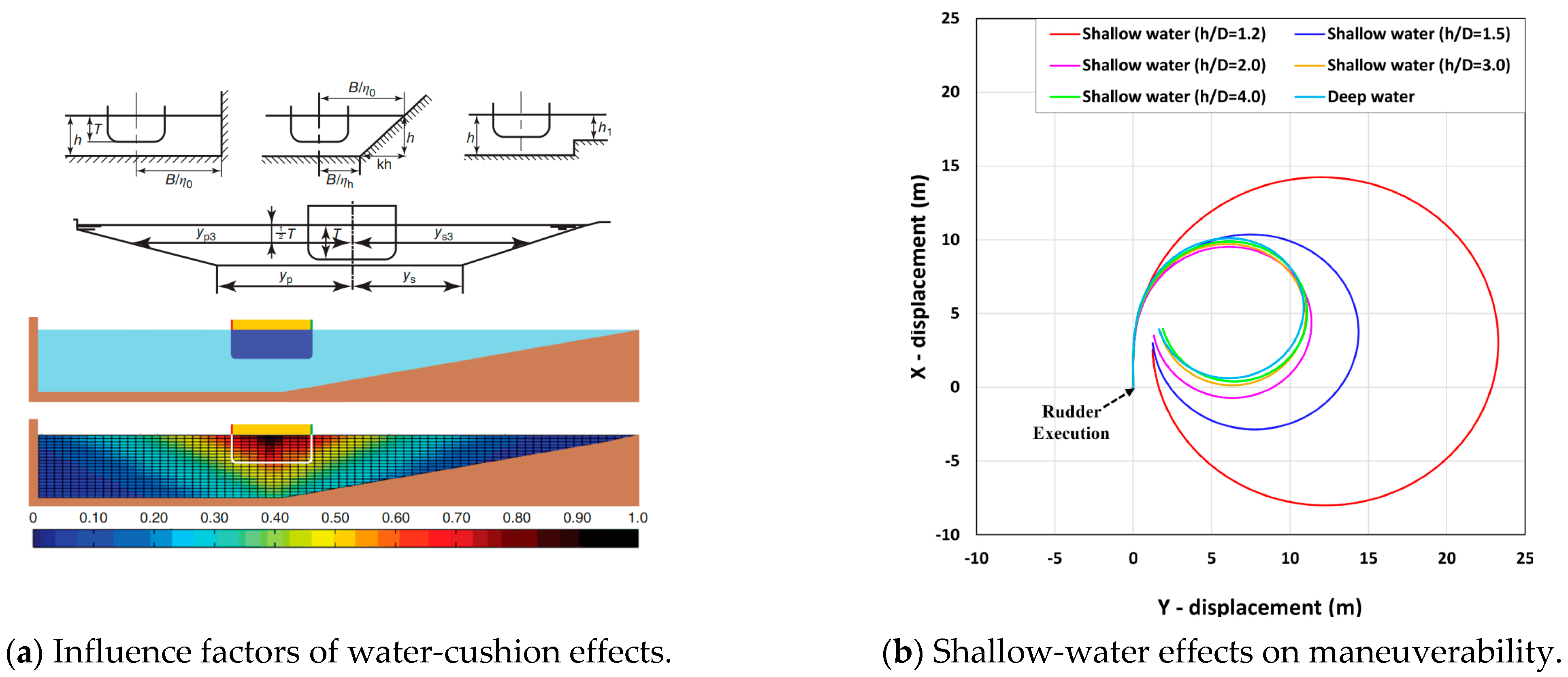
In the ship berthing process, the external disturbances mainly refer to the water-cushion effect (shallow-water effect, bank effect, and ship–ship interaction) (shown in Figure 13), wind, and current. All these phenomena could be attributed to the pressure distribution variation upon the ship hull, and finally lead to changes in ship resistance and attitude. The water-cushion effects occur in confined waters [103], the flow velocity difference is observed between the bow and stern section, or between the port side and starboard side, and the asymmetric flow causes pressure difference on a ship and makes additional resistance and amplitude variation. With regard to the wind, it acts on the superstructure of the ship, as the larger the windward area, the stronger the wind effect. And the current normally influences the resultant inflow velocity and angle to the thruster and rudder.

4.3.1. Shallow-Water Effect

In the harbor area, the water depth is relatively shallower, and the ship may be affected by the shallow-water effect. The shallow-water effect brings ship squat and trim and is affected by the under-keel clearance, ship speed, and seabed topography. It is commonly accepted that the shallow-water effect emerges when the water-depth-to-draft ratio (h/T) is smaller than 4; PIANC [105] made an arbitrary distinction among deep (h/T > 3.0 or UKC > 200%), medium deep (1.5 < h/T < 3.0), shallow (1.2 < h/T < 1.5), and very shallow water (h/T < 1.2). Moreover, to indicate the gravity influence on fluid motion or the characteristics of the wave-making resistance in shallow water, the Froude depth number Frh is induced [106]: Frh < 1 is called a subcritical flow, Frh ≈ 1 is denoted as a critical flow, and Frh > 1 is characterized as a supercritical flow. Generally, the shallower the water depth, the greater the shallow-water effect, namely the added resistance, ship squat, and trim amplitude increase with the decrease in water depth [104,107,108,109,110]. The decrease in water depth boosts the damping moment on the ship hull and leads to smaller turning angular velocity and drift angles, and in turn, the relatively small drift angle reduces the ship’s turning rate. Accordingly, the hull–propeller–rudder interaction factors are significantly affected [94,111] with the reduction in water depth; the thrust reduction factor tp [112], effective wake coefficient ωp [113], and rudder force increase factor αH present an increasing tendency, the acting point of the rudder-induced additional lateral force (xH) moves towards the bow slightly, and the flow straightening coefficient γR drops by a specific point and reverses to growth [112], namely, follows the cubic parabola trend. As for the steering resistance deduction factor tR [112], it is assumed to be constant, like the deep-water conditions. As a result, in shallow-water maneuvering conditions, ships obtain better sailing and heading stability, and worse turning ability.

4.3.2. Bank Effect

The ship berthing maneuver is the process of approaching and stopping near the quay wall, and the ship is influenced by the bank effect under such conditions. The bank effect arouses the bow cushion, bank suction, and heel, and is affected by ship–bank distance, ship speed, water depth, propeller action, and bank geometry [114]. Most of these parameters and their influence on bank effects are not independent of each other. Generally, no significant bank influence is observed when the bank proximity distance is greater than three times the ship breadth [115]; within the ship-to-bank distance spectrum of [0.25B, B], the bank effects are most significant, and the interaction effects increase dramatically as the lateral distance decreases [116]. Lataire [117] conducted over 10,000 captive model tests to investigate the influence of bank characteristics on ship–bank interaction: for instance, the distance of significant influence of a ship to a vertical piercing bank is introduced as a function of ship breadth and Froude depth number, and the lateral force and yaw moment induced by the submerged slop bank is expressed as an exponential function of that induced by the surface piercing bank [118]. In brief, the closer the ship–bank distance, the faster the ship speed, and the shallower the water depth, the severer the bank effects. Furthermore, under extreme shallow-water conditions (1.1 < h/T < 1.25), the bank repulsion effect is observed on the bare hull; however, due to the propeller revolution, the bank repulsion changes into bank attraction. With regard to the hydrodynamic derivatives, it is found to make a relatively small difference, compared to shallow-water conditions [119]. Hence, for safe navigation of self-berthing ships, it is necessary to maintain larger rudder angles than in the conventional operation [120] and to take the helm to direct the bow towards the closet bank, to compensate for the bank-induced yaw moment [104].

4.3.3. Ship–Ship Interaction

The ship–ship interaction induces ship attraction, repulsion, and heel, and is affected by ship status (overtaking, head-on, parallel, and moored-passing), ship–ship distance, ship speed, water depth, and ship dimension and profile, and by secondary influences from the propeller and rudder [121]. The hydrodynamic interactions vanish when the longitudinal distance between adjacent ships is larger than twice the ship length [122]. Generally, for safety berthing concerns, such a close interval is not supposed to be allowed or observed in the self-berthing process. As for the tug-assistant berthing, with over four times the scale, tugs would not exert any significant influence on the own-ship either. Consequently, the ship–ship interaction could be ignored in the studies on ship berthing, hydrodynamic performance and maneuverability modeling.

4.3.4. Wind and Current

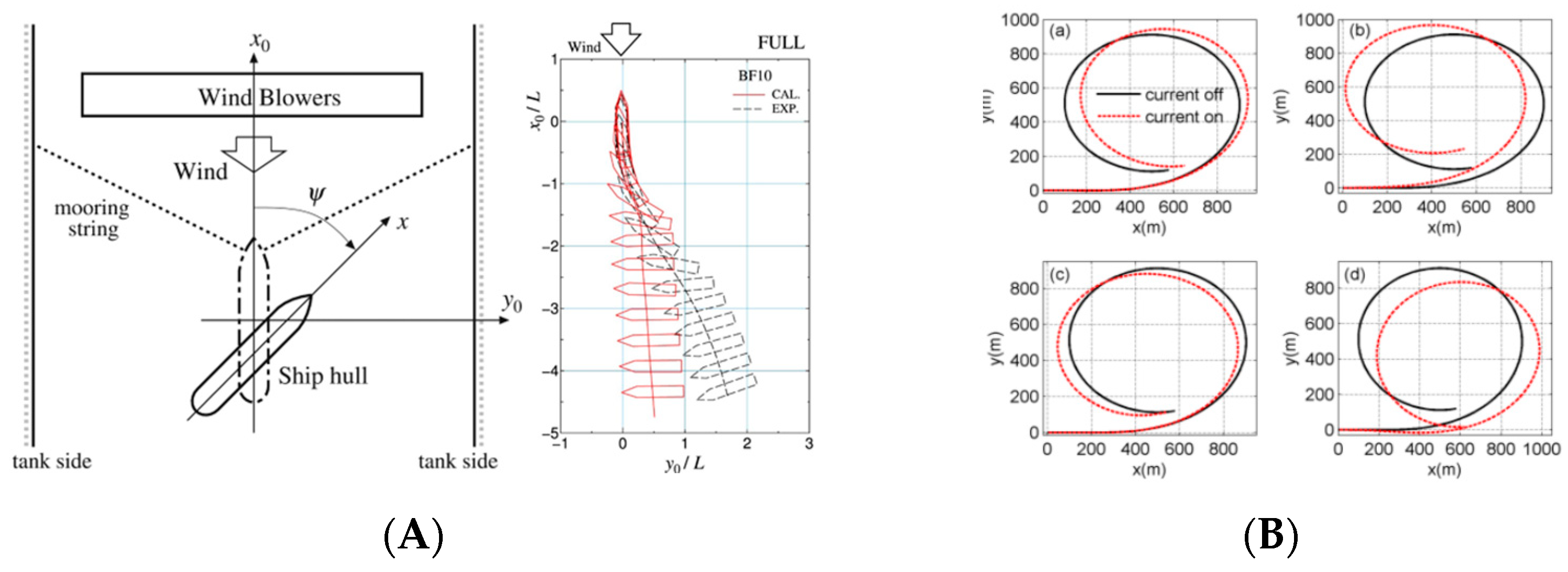
The external disturbances in the berthing period mainly refer to the wind and current effects. As shown in Figure 14, ship floating is observed along the wind or current-flow direction. The wind acts upon the ship’s superstructure, and the wind load influence on ship maneuverability becomes much more apparent when the ship’s speed is lower than the wind speed. Wind forces the ship to drift off course and decreases ship stability. Knowing the wind load characteristics could help avoid collisions from happening and improve the feasibility under certain conditions. Refs. [123,124,125] summarize the wind effect on ship maneuverability as a function of ship speed, wind speed, wind direction, and windward area; such a functional relation could be utilized to estimate the wind damping force. Moreover, the wind has a significant effect on ship speed loss under the scope of head-to-beam wind direction, and, compared with this, ship stability gradually degrades within the range from beam wind to quartering wind [126,127,128]. Furthermore, with the increase in wind velocity, the rudder becomes less effective [129]. The wind effect on the ship hull could be expressed as:
{ X w i n d = 0.5 ρ A o U r 2 C w x ( α r ) Y w i n d = 0.5 ρ A l U r 2 C w y ( α r ) N w i n d = 0.5 ρ A l L o a U r 2 C w n ( α r ) ,
where Ao is the orthographic projection area above the waterline, Al the lateral projection area above the waterline, Ur the relative wind speed, Cwx, and Cwy are the wind pressure force coefficients on the x and y axes, Cwn is the wind pressure moment coefficient around the z axis, and αr is the relative wind angle.
Affected by the wind, wave, tide, seabed topography, and obstacles, currents behave non-uniformly in both the horizontal and vertical direction. However, studies such as [131] indicated that it is acceptable to concern the horizontal current flow, due to the uncertainty of which it is hard to directly express the complex and random current flow; hence, present works are performed on the uniform and steady current. The current flow mainly affects the flow around the ship, and it is essential to contain the current effect for small ships, as its impact on speed over the ground outweighs the wind effect [132]. The modeling of steady current is relatively simple: the ship speed U over ground is resolved into the current velocity Uc and the ship speed U0 relative to the current, and the hydrodynamic characteristics and the interactions among the hull, propeller, and propeller are solved based on the ship’s speed relative to the current. The ship’s longitudinal and lateral speed relative to the current are expressed as:
{ u r = u u c = u U c cos ( ψ c ψ ) v r = v v c = v U c sin ( ψ c ψ ) ,
where, ur and vr are the ship’s longitudinal and lateral speed relative to the current, u and v are the ship’s longitudinal and lateral speed relative to the ground, uc and vc are the current speed, ψ is the heading angle, and ψc is the current angle.

4.4. Auxiliary Devices

The berthing process requires the ship to maintain a low or extremely low speed, and under such working conditions a larger rudder steerage is utilized to rectify the heading deviation and keep the course; otherwise, the ship would lose its rudder effects. Resolution is carried out with the introduction of auxiliary devices such as side thrusters, tugs, and anchors. The diagram is shown in Figure 15.

4.4.1. Side Thruster

The side thruster, especially the bow thruster, is used to provide lateral force and yaw moment for slewing motions. Normally, for best-turning effects, bow thrusters are assembled as far forward as possible or under the bottom of the keel. Studies [136,137] indicated that a ship’s forward speed has a great influence on the effectiveness of the bow thruster, and that the generated force decreases remarkably with the increase in ship speed. As for the lateral force induced by the bow thruster, the drifting effect of the ship hull should be considered when the drift angle is over 10°, while the yaw moment seems to be immune to the ship’s drifting.

4.4.2. Tug Assistance

In the berthing process, whether it is for ships with small displacement, or ships with larger dimensions, the essential indices for ship berthing are the same, namely the approaching angle, lateral speed, and wall distance. Tugs are utilized to release the berthing risk and improve efficiency. Based on the survey of 15 ports in China, 120 m of the ship length is normally regarded as a boundary for tug usage [138], and it is acceptable for ships with shorter ship lengths to conduct self-berthing. As for ships with greater dimensions, it is mandatory to change direction, turn around, pull up, and parallel berth with the assistance of tugboats [139]. However, when it comes to liquid cargo ships, engineering ships, ships with damage, extreme weather, and other conditions, ships are obliged to berth with tugs.
Tugs assist the target ship in a direct (pushing) or indirect (towing) way, to lead the ship to the quay/berthing place, and maintain proper speed and attitude. There are two methods expressing the tug direct tug pushing in berthing maneuver modeling: one treats the tug-induced force as an azimuth external force, and the motion and specifications of the tug itself are eliminated. The other takes the pusher–barge system for reference and regards the pusher and the barge as integral. Yang [140,141] simplified the tug as a force and obtained acceptable accuracy on berthing operation mathematical modeling and harbor area navigation simulations. Series studies [134,142,143,144] were carried out on an inland pusher–barge-system maneuvering modeling, which analyzed the effects of barge ship formation, the profile, numbers, and pusher locations on the system, discussed the resistance variation and thrust efficiency, and established the mathematical model to predict the turning and course keeping ability of the system. In conclusion, the modeling method of the pusher–barge system is similar to the individual ship, and this method could be expanded to the modeling study on tug-pushing modeling in the berthing process.
The modeling of indirect towing via cables is complicated. The tug-towed system involves three closely related parts, the tug, the towed ship, and the cable line, which are connected to each other. From the point of view of mathematical modeling, researchers [126,135,145,146,147,148] conducted massive work on the force characteristics of the system and the individuals in linear and non-linear conditions, indicating that the focuses of the system are the cable length, towing point locations, cable angles, and cable status. Considering that the slack towing line evokes impulse forces, which adds risk to the towing operation, it is suggested that the cables are kept under strain.
The anchor functions through the cables, and the resolution is similar to the tug-towed system.

4.5. Remarks

As the ship conducts self-berthing or berthing with tug assistance, the force characteristics are completely different from the traditional maneuvers. The hydrodynamic performance, four-quadrant propulsion and steerage devices, external disturbances, and auxiliary devices, are the four main aspects. The hydrodynamic performance indicates the hydrodynamic forces acting on the hull under low-speed, high-drifting and high-yaw-rate conditions, and the cross-flow drag is the main concern. The four-quadrant propulsion and steerage performances focus on the propeller thrust and rudder steerage force under arbitrary resultant inflow angles. Ships in the berthing process are sensitive to external disturbances, especially the shallow-water and bank effects caused by the water-cushion effect, wind pressure provoked by the wind, and flow speed variation induced by the tidal current. Hydrodynamic forces, four-quadrant propulsion and steerage devices are essential to the berthing maneuver modeling; the external disturbances and auxiliary devices are supplementary to the model’s scope and accuracy.

5. Conclusions

An autonomous ship is encouraged by the increasing shipping demand and technology, and automatic berthing control is at the top level of ship autonomy, due to the complicated and dangerous low-speed operation. A precise berthing maneuver model is the foundation for the automatic control system, providing a reference for the utilization of auxiliary devices and offering the responses of the ship’s motion within the berthing aid system to the steerage operation and external disturbances.
In the present work, a bibliometric study on automatic ship berthing is performed to search for the important issues, and six specific study fields are obtained: risk assessment, perception utilization, motion control, maneuverability modeling, scheduling optimization, and emission supervision. With regard to automatic berthing, risk assessment is the guarantee, perception utilization is the premise, motion control is the key, and maneuver modeling is the foundation.
The modular MMG mathematical model is found to better describe ship motion and responses to internal operation and external disturbances. Both conventional MMG and berthing maneuver MMG models are adopted in the automatic berthing control studies. To make clear the similarities and differences, the following difficult questions are discussed:
(1)
What are the similarities and differences between the conventional MMG maneuvering model and the automatic berthing maneuvering model?
(2)
How can an accurate automatic berthing maneuvering model be established?
Uniform mathematical modeling methods (data-based, system-based, and CFD-based methods) could be used to establish the conventional MMG model and the berthing maneuver MMG model. Moreover, four specified characteristics of berthing maneuver are concluded to exist: low-speed-, high-drifting- and high-yaw-rate-induced hydrodynamic forces, the arbitrary resultant inflow angle causing four-quadrant thrust and steerage performances, external disturbances provoked by the water-cushion effects, wind, and tidal currents, and the additional forces provided by auxiliary devices.
With the aim of practical use, future work is put on the agenda for establishing the mathematical model expressing the berthing maneuver and comparing and validating the applicability and accuracy of the conventional MMG model and berthing maneuver MMG model.

Author Contributions

Conceptualization, J.L.; methodology, S.Z., J.L. and Y.H.; software, S.Z. and Y.H.; validation, S.Z.; formal analysis, S.Z. and Y.H.; investigation, S.Z., J.L. and Y.H.; data curation, S.Z., J.L. and Y.H.; writing—original draft preparation, S.Z., and Y.H.; writing—review and editing, Q.W., J.L. and S.L.; visualization, S.Z., and Y.H.; supervision, Q.W. and J.L.; project administration, J.L.; funding acquisition, J.L. and S.L. All authors have read and agreed to the published version of the manuscript.

Funding

This research was funded by the National Key R&D Program of China, grant number 2022YFB4301402, the National Natural Science Foundation of China, grant number 52272425 and 62003250.

Institutional Review Board Statement

Not applicable.

Informed Consent Statement

Not applicable.

Data Availability Statement

Not applicable.

Conflicts of Interest

The authors declare no conflict of interest.

References

  1. Rothblum, A.M. Human error and marine safety. In Proceedings of the National Safety Council Congress and Expo, Orlando, FL, USA, 16–18 October 2000. [Google Scholar]
  2. Ahmed, Y.A.; Hasegawa, K. Implementation of automatic ship berthing using artificial neural network for free running experiment. IFAC Proc. Vol. 2013, 46, 25–30. [Google Scholar] [CrossRef]
  3. China Classification Society. Rules for Intelligent Ships; China Classification Society: Ningbo, China, 2015. [Google Scholar]
  4. China Classification Society. Rules for Intelligent Ships; China Classification Society: Ningbo, China, 2020. [Google Scholar]
  5. China Classification Society. Rules for Intelligent Ships; China Classification Society: Ningbo, China, 2023. [Google Scholar]
  6. Executive, T.M. Video: Japanese Demonstration of Autonomous Docking System. Available online: https://maritime-executive.com/article/video-japanese-demonstration-of-autonomous-docking-system (accessed on 24 May 2021).
  7. SAFETY4SEA. Watch: World’s First Successful Trail of Auto Berthing and un-Berthing System. Available online: https://safety4sea.com/watch-worlds-first-successful-trial-of-auto-berthing-and-un-berthing-system/ (accessed on 24 May 2021).
  8. Executive, T.M. First Autonomous Navigation and Berthing Test on a Containership. Available online: https://maritime-executive.com/article/first-autonomous-navigation-and-berthing-test-on-a-containership (accessed on 25 January 2022).
  9. Project, K.A.S.S. Detailed Task. Available online: https://kassproject.org/en/task/task.php (accessed on 24 May 2021).
  10. Qingdaonews. Water Test of the First Domestic Autonomous Navigation System Experimental Ship. Available online: https://news.qingdaonews.com/qingdao/2019-05/17/content_20362302.htm (accessed on 17 May 2019).
  11. Brilliance, N. The First Unmanned Container Ship in China Successfully Undocked. Available online: http://www.brinav.com/pages/News/NewsDetails.aspx?ID=2022 (accessed on 1 July 2021).
  12. Rolls-Royce. Rolls-Royce and Finferries Demonstrate World’s First Fully Autonomous Ferry. Available online: https://www.rolls-royce.com/media/press-releases/2018/03-12-2018-rr-and-finferries-demonstrate-worlds-first-fully-autonomous-ferry.aspx (accessed on 3 December 2018).
  13. Corporation, W. World’s first Autodocking Installation Successfully Tested by Wärtsilä. Available online: https://www.wartsila.com/media/news/26-04-2018-world-s-first-autodocking-installation-successfully-tested-by-wartsila-2169290 (accessed on 26 April 2018).
  14. MARITIME, K. Autonomous Ship Project, Key Facts About Yara Birkeland: The Zero Emission, Autonomous Container Feeder. Available online: https://www.kongsberg.com/zh-hans/maritime/support/themes/autonomous-ship-project-key-facts-about-yara-birkeland/ (accessed on 24 May 2021).
  15. PENTA, V. Launching the First Fully Integrated Assisted Docking System. Available online: https://www.volvopenta.com/about-us/news-page/2021/jan/launching-the-first-fully-integrated-assisted-docking-system/ (accessed on 24 May 2021).
  16. Yasukawa, H.; Yoshimura, Y. Introduction of MMG standard method for ship maneuvering predictions. J. Mar. Sci. Technol. 2015, 20, 37–52. [Google Scholar] [CrossRef]
  17. Li, J.; Goerlandt, F.; Reniers, G. Mapping process safety: A retrospective scientometric analysis of three process safety related journals (1999–2018). J. Loss Prev. Process Ind. 2020, 65, 104141. [Google Scholar] [CrossRef]
  18. Li, J.; Goerlandt, F.; Reniers, G. An overview of scientometric mapping for the safety science community: Methods, tools, and framework. Saf. Sci. 2021, 134, 105093. [Google Scholar] [CrossRef]
  19. He, Y.; Mou, J.; Chen, L.; Zeng, Q.; Chen, P.; Zhang, S. Survey on hydrodynamic effects on cooperative control of Maritime Autonomous Surface Ships. Ocean. Eng. 2021, 235, 109300. [Google Scholar] [CrossRef]
  20. Koyama, T.; Yan, J.; Huan, J.K. A systematic study on automatic berthing control (1st report). J. Soc. Nav. Archit. Jpn. 1987, 1987, 201–210. [Google Scholar] [CrossRef]
  21. Shouji, K.; Ohtsu, K.; Mizoguchi, S. An automatic berthing study by optimal control techniques. IFAC Proc. Vol. 1992, 25, 185–194. [Google Scholar] [CrossRef]
  22. Yamato, H.; Koyama, T.; Nakagawa, T. Automatic berthing system using expert system. J. Soc. Nav. Archit. Jpn. 1993, 1993, 327–337. [Google Scholar] [CrossRef]
  23. Meng, W.; Li, G.; Hua, L. A goal-programming based optimal port docking scheme under COVID-19. Ocean. Coast. Manag. 2022, 225, 106222. [Google Scholar]
  24. Han, S.; Wang, L.; Wang, Y. A potential field-based trajectory planning and tracking approach for automatic berthing and COLREGs-compliant collision avoidance. Ocean. Eng. 2022, 266, 112877. [Google Scholar] [CrossRef]
  25. Lee, H.-T.; Lee, J.-S.; Son, W.-J.; Cho, I.-S. Development of machine learning strategy for predicting the risk range of ship’s berthing velocity. J. Mar. Sci. Eng. 2020, 8, 376. [Google Scholar] [CrossRef]
  26. Liao, Y.; Jia, Z.; Zhang, W.; Jia, Q.; Li, Y. Layered berthing method and experiment of unmanned surface vehicle based on multiple constraints analysis. Appl. Ocean. Res. 2019, 86, 47–60. [Google Scholar] [CrossRef]
  27. Gravendeel, A.; Noorland, J.; Jacobs, S. Automatic Berthing; Mainport Rotterdam University: Rotterdam, Netherlands, 2017. [Google Scholar]
  28. Digerud, L.; Volden, Ø.; Christensen, K.A.; Kohtala, S.; Steinert, M. Vision-based positioning of Unmanned Surface Vehicles using Fiducial Markers for automatic docking. IFAC-Pap. Online 2022, 55, 78–84. [Google Scholar] [CrossRef]
  29. Wang, Z.; Zhang, Y. Estimation of ship berthing parameters based on Multi-LiDAR and MMW radar data fusion. Ocean. Eng. 2022, 266, 113155. [Google Scholar] [CrossRef]
  30. Hu, B.; Liu, X.; Jing, Q.; Lyu, H.; Yin, Y. Estimation of berthing state of maritime autonomous surface ships based on 3D LiDAR. Ocean. Eng. 2022, 251, 111131. [Google Scholar] [CrossRef]
  31. Chen, L.; Negenborn, R.; Huang, Y.; Hopman, H. Survey on cooperative control for waterborne transport. IEEE Intell. Transp. Syst. Mag. 2020, 13, 71–90. [Google Scholar] [CrossRef]
  32. Bitar, G.I. Towards the Development of Autonomous Ferries; NTNU: Trondheim, Norway, 2017. [Google Scholar]
  33. Zhang, Q.; Im, N.-K.; Ding, Z.; Zhang, M. Review on the research of ship automatic berthing control. In Offshore Robotics Volume I Issue 1, 2021; Springer: Singapore, 2022; pp. 87–109. [Google Scholar]
  34. de Kruif, B.J. Applied trajectory generation to dock a feeder vessel. IFAC-Pap. Online 2022, 55, 172–177. [Google Scholar] [CrossRef]
  35. Wang, X.; Deng, Z.; Peng, H.; Wang, L.; Wang, Y.; Tao, L.; Lu, C.; Peng, Z. Autonomous docking trajectory optimization for unmanned surface vehicle: A hierarchical method. Ocean. Eng. 2023, 279, 114156. [Google Scholar] [CrossRef]
  36. Bitar, G.; Martinsen, A.B.; Lekkas, A.M.; Breivik, M. Trajectory planning and control for automatic docking of ASVs with full-scale experiments. IFAC-Pap. Online 2020, 53, 14488–14494. [Google Scholar] [CrossRef]
  37. Rachman, D.M.; Maki, A.; Miyauchi, Y.; Umeda, N. Warm-started semionline trajectory planner for ship’s automatic docking (berthing). Ocean. Eng. 2022, 252, 111127. [Google Scholar] [CrossRef]
  38. Bidikli, B.; Tatlicioglu, E.; Zergeroglu, E. Robust dynamic positioning of surface vessels via multiple unidirectional tugboats. Ocean. Eng. 2016, 113, 237–245. [Google Scholar] [CrossRef]
  39. Du, Z.; Reppa, V.; Negenborn, R.R. Cooperative control of autonomous tugs for ship towing. IFAC-Pap. Online 2020, 53, 14470–14475. [Google Scholar] [CrossRef]
  40. Wu, G.; Zhao, X.; Sun, Y.; Wang, L. Cooperative maneuvering mathematical modeling for multi-tugs towing a ship in the port environment. J. Mar. Sci. Eng. 2021, 9, 384. [Google Scholar] [CrossRef]
  41. Wang, S.; Sun, Z.; Yuan, Q.; Sun, Z.; Wu, Z.; Hsieh, T.-H. Autonomous piloting and berthing based on Long Short Time Memory neural networks and nonlinear model predictive control algorithm. Ocean. Eng. 2022, 264, 112269. [Google Scholar] [CrossRef]
  42. Nguyen, V.S. Investigation on a novel support system for automatic ship berthing in marine practice. J. Mar. Sci. Eng. 2019, 7, 114. [Google Scholar] [CrossRef]
  43. Baek, S.; Woo, J. Model reference adaptive control-based autonomous berthing of an unmanned surface vehicle under environmental disturbance. Machines 2022, 10, 244. [Google Scholar] [CrossRef]
  44. Xu, Z.; Galeazzi, R. Guidance and Motion Control for Automated Berthing of Twin-waterjet Propelled Vessels. IFAC-Pap. Online 2022, 55, 58–63. [Google Scholar] [CrossRef]
  45. Martinsen, A.B.; Bitar, G.; Lekkas, A.M.; Gros, S. Optimization-based automatic docking and berthing of ASVs using exteroceptive sensors: Theory and experiments. IEEE Access 2020, 8, 204974–204986. [Google Scholar] [CrossRef]
  46. Mizuno, N.; Kuboshima, R. Implementation and evaluation of non-linear optimal feedback control for ship’s automatic berthing by recurrent neural network. IFAC-Pap. Online 2019, 52, 91–96. [Google Scholar] [CrossRef]
  47. Nguyen, V.S. Investigation of a multitasking system for automatic ship berthing in marine practice based on an integrated neural controller. Mathematics 2020, 8, 1167. [Google Scholar] [CrossRef]
  48. Mizuno, N.; Koide, T. Application of Reinforcement Learning to Generate Non-linear Optimal Feedback Controller for Ship’s Automatic Berthing System. IFAC-Pap. Online 2023, 56, 162–168. [Google Scholar] [CrossRef]
  49. Shimizu, S.; Nishihara, K.; Miyauchi, Y.; Wakita, K.; Suyama, R.; Maki, A.; Shirakawa, S. Automatic berthing using supervised learning and reinforcement learning. Ocean. Eng. 2022, 265, 112553. [Google Scholar] [CrossRef]
  50. Chopra, K. A Detailed Explanation of How a Ship Is Manoeuvered to a Port. Available online: https://www.marineinsight.com/guidelines/a-detailed-explanation-of-how-a-ship-is-manoeuvered-to-a-port/ (accessed on 4 March 2021).
  51. Wakita, K.; Akimoto, Y.; Rachman, D.M.; Miyauchi, Y.; Naoya, U.; Maki, A. Collision probability reduction method for tracking control in automatic docking/berthing using reinforcement learning. arXiv 2022, arXiv:2212.06415. [Google Scholar]
  52. Abkowitz, M.A. Lectures on Ship Hydrodynamics-Steering and Manoeuvrability; Hydro & Aerodynamic Laboratory: Lyngby, Denmark, 1964. [Google Scholar]
  53. Fossen, T.I. Handbook of Marine Craft Hydrodynamics and Motion Control; John Wiley & Sons: Hoboken, NJ, USA, 2011. [Google Scholar]
  54. Nomoto, K.; Taguchi, K.; Honda, K.; Hirano, S. On the steering qualities of ships. J. Zosen Kiokai 1956, 1956, 75–82. [Google Scholar] [CrossRef]
  55. Wang, Z.; Kim, J.; Im, N. Non-parameterized ship maneuvering model of Deep Neural Networks based on real voyage data-driven. Ocean. Eng. 2023, 284, 115162. [Google Scholar] [CrossRef]
  56. Ouyang, Z.; Liu, S.; Zou, Z. Nonparametric modeling of ship maneuvering motion in waves based on Gaussian process regression. Ocean. Eng. 2022, 264, 112100. [Google Scholar] [CrossRef]
  57. Im, N. A study on ship automatic berthing with assistance of auxiliary devices. Int. J. Nav. Archit. Ocean. Eng. 2012, 4, 199–210. [Google Scholar]
  58. Li, S.; Liu, J.; Negenborn, R.R.; Wu, Q. Automatic docking for underactuated ships based on multi-objective nonlinear model predictive control. IEEE Access 2020, 8, 70044–70057. [Google Scholar] [CrossRef]
  59. Piao, Z.; Guo, C.; Sun, S. Research into the automatic berthing of underactuated unmanned ships under wind loads based on experiment and numerical analysis. J. Mar. Sci. Eng. 2019, 7, 300. [Google Scholar] [CrossRef]
  60. Zhang, Q.; Zhu, G.; Hu, X.; Yang, R. Adaptive neural network auto-berthing control of marine ships. Ocean. Eng. 2019, 177, 40–48. [Google Scholar] [CrossRef]
  61. Wu, G.; Zhao, X.; Wang, L. Modeling and Simulation of Automatic Berthing based on Bow and Stern Thruster Assist for Unmanned Surface Vehicle. J. Mar. Sci. Eng. 2021, 3, 16–21. [Google Scholar] [CrossRef]
  62. Ahmed, Y.A.; Hannan, M.A.; Siang, K.H. Artificial Neural Network controller for automatic ship berthing: Challenges and opportunities. Mar. Syst. Ocean. Technol. 2020, 15, 217–242. [Google Scholar] [CrossRef]
  63. Ahmed, Y.A.; Hasegawa, K. Automatic ship berthing using artificial neural network trained by consistent teaching data using nonlinear programming method. Eng. Appl. Artif. Intell. 2013, 26, 2287–2304. [Google Scholar] [CrossRef]
  64. Hasegawa, K.; Kitera, K. Mathematical model of manoeuvrability at low advance speed and its application to berthing control. In Proceedings of the 2nd Japan-Korea Joint Workshop of Ship and Marine Hydrodynamics, Osaka, Japan, 28–30 June 1993; pp. 144–153. [Google Scholar]
  65. Miyauchi, Y.; Maki, A.; Umeda, N.; Rachman, D.M.; Akimoto, Y. System parameter exploration of ship maneuvering model for automatic docking/berthing using CMA-ES. J. Mar. Sci. Technol. 2022, 27, 1065–1083. [Google Scholar] [CrossRef]
  66. Sawada, R.; Hirata, K.; Kitagawa, Y. Automatic berthing control under wind disturbances and its implementation in an embedded system. J. Mar. Sci. Technol. 2023, 452–470. [Google Scholar] [CrossRef]
  67. Okuda, R.; Yasukawa, H.; Yamashita, T.; Matsuda, A. Maneuvering simulations at large drift angles of a ship with a flapped rudder. Appl. Ocean. Res. 2023, 135, 103567. [Google Scholar] [CrossRef]
  68. Yoshimura, Y.; Nakao, I.; Ishibashi, A. Unified mathematical model for ocean and harbour manoeuvring. In Proceedings of the MARSIM2009, Panama City, FL, USA, 17–20 August 2009. [Google Scholar]
  69. ITTC. The Manoeuvring Committee Final Report and Recommendations. In Proceedings of the 25th International Towing Tank Conference (ITTC), Fukuoka, Japan, 14–20 September 2008. [Google Scholar]
  70. Holtrop, J.; Mennen, G. A statistical power prediction method. Int. Shipbuild. Prog. 1978, 25, 290. [Google Scholar] [CrossRef]
  71. Kijima, K.; Katsuno, T.; Nakiri, Y.; Furukawa, Y. On the manoeuvring performance of a ship with theparameter of loading condition. J. Soc. Nav. Archit. Jpn. 1990, 1990, 141–148. [Google Scholar] [CrossRef]
  72. Yoshimura, Y.; Masumoto, Y. Hydrodynamic database and manoeuvring prediction method with medium high-speed merchant ships and fishing vessels. In Proceedings of the International MARSIM Conference, Singapore, 23–27 April 2012; pp. 1–9. [Google Scholar]
  73. Pekic, S. TT-Line Starts Sea Trials of Its 1st Green Ship. Available online: https://www.offshore-energy.biz/tt-line-starts-sea-trials-of-their-1st-green-ship/ (accessed on 19 November 2021).
  74. Zhang, Z.; Zhang, Y.; Wang, J.; Wang, H. Parameter identification and application of ship maneuvering model based on TO-CSA. Ocean Eng. 2022, 266, 113128. [Google Scholar] [CrossRef]
  75. Liu, S.; Ouyang, Z.; Chen, G.; Zhou, X.; Zou, Z. Black-box modeling of ship maneuvering motion based on Gaussian process regression with wavelet threshold denoising. Ocean Eng. 2023, 271, 113765. [Google Scholar] [CrossRef]
  76. Astrom, K.J.; Kallstrom, C.; Norrbin, N.; Bystrom, L. The identification of linear ship steering dynamics using maximum likelihood parameter estimation. Medd. Från Statens Skeppsprovningsanst. 1975, 75, 105. [Google Scholar]
  77. Banazadeh, A.; Ghorbani, M. Frequency domain identification of the Nomoto model to facilitate Kalman filter estimation and PID heading control of a patrol vessel. Ocean Eng. 2013, 72, 344–355. [Google Scholar] [CrossRef]
  78. Zhang, G.; Zhang, X.; Pang, H. Multi-innovation auto-constructed least squares identification for 4 DOF ship manoeuvring modelling with full-scale trial data. ISA Trans. 2015, 58, 186–195. [Google Scholar] [CrossRef] [PubMed]
  79. Zhang, Y.; Wang, Z.; Zou, Z. Black-box modeling of ship maneuvering motion based on multi-output nu-support vector regression with random excitation signal. Ocean Eng. 2022, 257, 111279. [Google Scholar] [CrossRef]
  80. Xu, H.; Soares, C.G. Hydrodynamic coefficient estimation for ship manoeuvring in shallow water using an optimal truncated LS-SVM. Ocean Eng. 2019, 191, 106488. [Google Scholar] [CrossRef]
  81. He, H.; Wang, Z.; Zou, Z.; Liu, Y. Nonparametric modeling of ship maneuvering motion based on self-designed fully connected neural network. Ocean Eng. 2022, 251, 111113. [Google Scholar] [CrossRef]
  82. Jiang, Y.; Hou, X.; Wang, X.; Wang, Z.; Yang, Z.; Zou, Z. Identification modeling and prediction of ship maneuvering motion based on LSTM deep neural network. J. Mar. Sci. Technol. 2022, 27, 125–137. [Google Scholar] [CrossRef]
  83. Guo, H.; Zou, Z.; Liu, Y.; Wang, F. Investigation on hull-propeller-rudder interaction by RANS simulation of captive model tests for a twin-screw ship. Ocean Eng. 2018, 162, 259–273. [Google Scholar] [CrossRef]
  84. Liu, Y.; Zou, L.; Zou, Z.; Guo, H. Predictions of ship maneuverability based on virtual captive model tests. Eng. Appl. Comput. Fluid Mech. 2018, 12, 334–353. [Google Scholar] [CrossRef]
  85. Liu, J.; Hekkenberg, R.; Quadvlieg, F.; Hopman, H.; Zhao, B. An integrated empirical manoeuvring model for inland vessels. Ocean Eng. 2017, 137, 287–308. [Google Scholar] [CrossRef]
  86. Lu, S.; Cheng, X.; Liu, J.; Li, S.; Yasukawa, H. Maneuvering modeling of a twin-propeller twin-rudder inland container vessel based on integrated CFD and empirical methods. Appl. Ocean. Res. 2022, 126, 103261. [Google Scholar] [CrossRef]
  87. Zhang, S.; Wu, Q.; Liu, J.; He, Y.; Li, S. Twin-screw ASD tug maneuvering prediction based on integrated CFD and empirical methods. Ocean Eng. 2023, 269, 113489. [Google Scholar] [CrossRef]
  88. Li, S.; Liu, C.; Chu, X.; Zheng, M.; Wang, Z.; Kan, J. Ship maneuverability modeling and numerical prediction using CFD with body force propeller. Ocean Eng. 2022, 264, 112454. [Google Scholar] [CrossRef]
  89. Jia, X.; Yang, Y. Ship motion mathematical model: Mechanism modeling and identification modeling; Dalian Maritime University Press: Dalian, China, 1999. [Google Scholar]
  90. Sutulo, S. Extension of polynomial ship mathematical models to arbitrary manoeuvres. In Proceedings of the The International Shipbuilding Conference in Commemoration of the Centenary of the Krylov Ship Research Institute (ISC), St. Petersburg, Russia, 8–12 October 1994; pp. 291–298. [Google Scholar]
  91. Sutulo, S.; Soares, C.G. Development of a core mathematical model for arbitrary manoeuvres of a shuttle tanker. Appl. Ocean. Res. 2015, 51, 293–308. [Google Scholar] [CrossRef]
  92. Yasukawa, H.; Hirata, N.; Nakayama, Y.; Matsuda, A. Drifting of a dead ship in wind. Ship Technol. Res. 2023, 70, 26–45. [Google Scholar] [CrossRef]
  93. Inoue, S.; Hirano, M.; Kijima, K. Hydrodynamic derivatives on ship manoeuvring. Int. Shipbuild. Prog. 1981, 28, 112–125. [Google Scholar] [CrossRef]
  94. Yoshimura, Y. Mathematical model for the manoeuvring ship motion in shallow water (2nd Report)-Mathematical model at slow forward speed. J. Kansai Soc. Nav. Archit. Jpn. 1988, 210, 77–84. [Google Scholar]
  95. Oltmann, P.; Sharma, S. Simulation of Combined Engine and Rudder Maneuvers Using an Improved Model of Hull-Propeller-Rudder Interactions; Hamburg University of Technology: Hamburg, Germany, 1984. [Google Scholar]
  96. Yasukawa, H.; Ishikawa, T.; Yoshimura, Y. Investigation on the rudder force of a ship in large drifting conditions with the MMG model. J. Mar. Sci. Technol. 2021, 26, 1078–1095. [Google Scholar] [CrossRef]
  97. Van Lammeren, W.; van Manen, J.v.; Oosterveld, M. The Wageningen B-Screw Series; National Academy of Sciences: Washington, DC, USA, 1969; Volume 77, p. 43. [Google Scholar]
  98. Yoshimura, Y.; Sasaki, N.; Takekawa, M. Prediction of ship manoeuvrability with a flapped rudder. J. Soc. Nav. Archit. Jpn. 1997, 1997, 191–196. [Google Scholar] [CrossRef]
  99. Huang, G.; Li, X.; Zhu, Y.; Nie, S. Experimental Study on Reaction Thrust Characteristics of Water Jet for Conical Nozzle. China Ocean Eng. 2009, 23, 669–678. [Google Scholar]
  100. Jiang, F.; Li, Y.; Gong, J. Study on the manoeuvre characteristics of a trimaran under different layouts by water-jet self-propulsion model test. Appl. Ocean. Res. 2021, 108, 102550. [Google Scholar] [CrossRef]
  101. Reichel, M. Prediction of manoeuvring abilities of 10000 DWT pod-driven coastal tanker. Ocean Eng. 2017, 136, 201–208. [Google Scholar] [CrossRef]
  102. Yasukawa, H.; Hirata, N.; Tanaka, S.; Kose, K. Study on Maneuverability of a Ship with Azimuthing Propellers. J. Jpn. Soc. Nav. Archit. Ocean. Eng. 2009, 9, 155–165. [Google Scholar]
  103. ITTC. ITTC Recommended Procedures and Guidelines. In Free Running Model Tests; No. 7.5-02-06-01; ITTC: Lawrence, KS, USA, 2008. [Google Scholar]
  104. Vantorre, M.; Eloot, K.; Delefortrie, G.; Lataire, E.; Candries, M.; Verwilligen, J. Maneuvering in shallow and confined water. In The Encyclopedia of Marine Offshore Engineering; Wiley Online Library: Hoboken, NJ, USA, 2017; pp. 1–17. [Google Scholar]
  105. Pianc. Capability of ship manoeuvring simulation models for approach channels and fairways in harbours. In Report of Working Group no. 20 of Permanent Technical Committee II. Supplement to Bulletin no. 77; Pianc: Brussels, Belgium, 1992. [Google Scholar]
  106. Havelock, T.H. The propagation of groups of waves in dispersive media, with application to waves on water produced by a travelling disturbance. Proc. R. Soc. London. Ser. A Contain. Pap. A Math. Phys. Character 1908, 81, 398–430. [Google Scholar]
  107. Delefortrie, G.; Eloot, K.; Lataire, E.; Van Hoydonk, W.; Vantorre, M. Captive model tests based 6 DOF shallow water manoeuvring model. In Proceedings of the 4th MASHCON-International Conference on Ship Manoeuvring in Shallow and Confined Water with Special Focus on Ship Bottom Interaction, Hamburg, Germany, 23–25 May 2016; pp. 273–286. [Google Scholar]
  108. Eloot, K. Selection, Experimental Determination and Evaluation of a Mathematical Model for Ship Manoeuvring in Shallow Water; Ghent University: Ghent, Belgium, 2006. [Google Scholar]
  109. Liu, Y.; Zou, Z.; Zou, L.; Fan, S. CFD-based numerical simulation of pure sway tests in shallow water towing tank. Ocean Eng. 2019, 189, 106311. [Google Scholar] [CrossRef]
  110. Zeng, Q.; Hekkenberg, R.; Thill, C. On the viscous resistance of ships sailing in shallow water. Ocean Eng. 2019, 190, 106434. [Google Scholar] [CrossRef]
  111. Yoshimura, Y.; Sakurai, H. Mathematical Model for the Manoeuvring Ship Motion in Shallow Water (3rd Report: Manoeuvrability of a Twin-propeller Twinrudder ship). J. Kansai Soc. Nav. Archit. Jpn. 1989, 211, 115–126. [Google Scholar]
  112. Yoshimura, Y. Mathematical model for the manoeuvring ship motion in shallow water-Application of MMG mathematical model to shallow water. J. Kansai Soc. Nav. Archit. Jpn. 1986, 200, 42–51. [Google Scholar]
  113. Kijima, K.; Yoshimura, Y.; Takashina, J. Report of MSS. 2: Mathematical model for ship maneuverability in shallow water. Bull. Soc. Nav. Archit. Jpn. 1989, 718, 207–220. [Google Scholar]
  114. ITTC. The Manoeuvring Committee–Final Report and Recommendations to the 23rd ITTC. In Proceedings of the Proceedings of the 23rd ITTC, Venice, Italy, 8–14 September 2002; pp. 153–234.
  115. Liu, H.; Ma, N.; Gu, X. Ship–bank interaction of a VLCC ship model and related course-keeping control. Ships Offshore Struct. 2017, 12, S305–S316. [Google Scholar] [CrossRef]
  116. Duan, W.; Liu, J.; Chen, J.; Wang, L. Comparison research of ship-to-ship hydrodynamic interaction in restricted water between TEBEM and other computational method. Ocean Eng. 2020, 202, 107168. [Google Scholar] [CrossRef]
  117. Lataire, E.; Vantorre, M.; Laforce, E.; Eloot, K.; Delefortrie, G. Navigation in confined waters: Influence of bank characteristics on ship-bank interaction. In Proceedings of the International Conference on Marine Research and Transportation, ICMRT, Naples, Italy, 19–21 September 2007; pp. 1–9. [Google Scholar]
  118. Norrbin, N.H. Bank clearance and optimal section shape for ship canals. In Proceedings of the 26th PIANC international navigation congress, Brussels, Belgium, 16–28 June 1985; pp. 167–178. [Google Scholar]
  119. Kijima, K. Calculation of the Derivatives on Ship Manoeuvring in Narrow Waterways by Rectangular Plate. J. Soc. Nav. Archit. Jpn. 1972, 1972, 155–163. [Google Scholar] [CrossRef]
  120. Yasukawa, H. Bank effect on ship maneuverability in a channel with varying width. Proc. Trans. West-Jpn. Soc. Nav. Archit. 1991, 81, 85–100. [Google Scholar]
  121. DeMarco Muscat-Fenech, C.; Sant, T.; Zheku, V.V.; Villa, D.; Martelli, M. A Review of Ship-to-Ship Interactions in Calm Waters. J. Mar. Sci. Eng. 2022, 10, 1856. [Google Scholar] [CrossRef]
  122. Vantorre, M.; Verzhbitskaya, E.; Laforce, E. Model test based formulations of ship-ship interaction forces. Ship Technol. Res. 2002, 49, 124–141. [Google Scholar]
  123. Fujiwara, T.; Ueno, M.; Nimura, T. Estimation of Wind Forces and Moments acting on Ships. J. Soc. Nav. Archit. Jpn. 1998, 1998, 77–90. [Google Scholar] [CrossRef]
  124. Isherwood, R.M. Wind resistance of merchant ships. Trans. RINA 1973, 115, 327–338. [Google Scholar]
  125. Yoshimura, Y.; Nagashima, J. Estimation of the Manoeuvring Behaviour of Ship in Uniform Wind. J. Soc. Nav. Archit. Jpn. 1985, 1985, 125–136. [Google Scholar] [CrossRef]
  126. Fitriadhy, A.; Yasukawa, H. Course stability of a ship towing system. Ship Technol. Res. 2011, 58, 4–23. [Google Scholar] [CrossRef]
  127. Kijima, K.; Varyani, K. Wind effect on course stability of two towed vessels. J. Soc. Nav. Archit. Jpn. 1985, 1985, 137–148. [Google Scholar] [CrossRef]
  128. Kijima, K.; Wada, Y. Course stability of towed vessel with wind effect. J. Soc. Nav. Archit. Jpn. 1983, 1983, 117–126. [Google Scholar] [CrossRef]
  129. Yasukawa, H.; Hirono, T.; Nakayama, Y.; Koh, K.K. Course stability and yaw motion of a ship in steady wind. J. Mar. Sci. Technol. 2012, 17, 291–304. [Google Scholar] [CrossRef]
  130. Wang, Y.; Du, W.; Li, G.; Li, Z.; Hou, J.; Hu, H. Efficient Ship Maneuvering Prediction with Wind, Wave and Current Effects; IOS Press: Clifton, VA, USA, 2022. [Google Scholar]
  131. Chislett, M.S.; Wied, S. A note on the mathematical modelling of ship manoeuvring in relation to a nautical environment with particular reference to currents. In Proceedings of the International Conference on Numerical and Hydraulic Modelling of Ports and Harbours, Birmingham, UK, 23–25 April 1985; pp. 1–11. [Google Scholar]
  132. Zhou, Y.; Daamen, W.; Vellinga, T.; Hoogendoorn, S.P. Impacts of wind and current on ship behavior in ports and waterways: A quantitative analysis based on AIS data. Ocean Eng. 2020, 213, 107774. [Google Scholar] [CrossRef]
  133. Feng, Y.; Chen, Z.; Dai, Y.; Zhang, Z.; Wang, P. An experimental and numerical investigation on hydrodynamic characteristics of the bow thruster. Ocean Eng. 2020, 209, 107348. [Google Scholar] [CrossRef]
  134. Koh, K.K.; Yasukawa, H.; Hirata, N.; Kose, K. Maneuvering simulations of pusher-barge systems. J. Mar. Sci. Technol. 2008, 13, 117–126. [Google Scholar]
  135. Fitriadhy, A.; Yasukawa, H.; Maimun, A. Theoretical and experimental analysis of a slack towline motion on tug-towed ship during turning. Ocean. Eng. 2015, 99, 95–106. [Google Scholar] [CrossRef]
  136. Fujino, M.; Saruta, T.; IDA, T. Experimental studies on the effectiveness of the side thruster. J. Kansai Soc. Nav. Archit. 1978, 168, 35–44. [Google Scholar]
  137. Kijima, K. The Effect of Drift Angle on Side Thruster Performance. Trans. West-Jpn. Soc. Nav. Archit. 1977, 54, 179–192. [Google Scholar]
  138. Zhang, S.; Liu, J.; Li, S.; Ye, J. System design and key technology of ship automatic berthing and unberthing. China Ship Surv. 2022, 10, 42–47. [Google Scholar]
  139. Yang, Y. Study on ship manoeuvring mathematical model in shiphandling simulator. In Marine Simulation and Ship Manoeuvrability; Routledge: London, UK, 1996; pp. 607–615. [Google Scholar]
  140. Yang, Y. Study on mathematical model for simulating ship berthing or unberthing (in Chinese). J. Dalian Marit. Univ. 1996, 22, 11–15. [Google Scholar]
  141. Yang, Y.; Fang, X. Study on Ship Maneuvering Mathematical Model with Assistance of Tugs in the Harbor. Navig. China 1997, 2, 19–24. (In Chinese) [Google Scholar]
  142. Koh, K.K.; Yasukawa, H. Comparison study of a pusher–barge system in shallow water, medium shallow water and deep water conditions. Ocean Eng. 2012, 46, 9–17. [Google Scholar] [CrossRef]
  143. Koh, K.K.; Yasukawa, H.; Hirata, N. Hydrodynamic derivatives investigation of unconventionally arranged pusher-barge systems. J. Mar. Sci. Technol. 2008, 13, 256–268. [Google Scholar] [CrossRef]
  144. Yasukawa, H.; Hirata, N.; Koh, K.K.; Krisana, P.; Kose, K. Hydrodynamic Force Chracteristics on Maneuvering of Pusher-Barge Systems. J. Jpn. Soc. Nav. Archit. Ocean. Eng. 2007, 5, 133–142. [Google Scholar] [CrossRef]
  145. Fitriadhy, A.; Yasukawa, H. Turning ability of a ship towing system. Ship Technol. Res. 2011, 58, 112–124. [Google Scholar] [CrossRef]
  146. Kishimoto, T.; Kijima, K. The manoeuvring characteristics on tug-towed ship systems. IFAC Proc. Vol. 2001, 34, 173–178. [Google Scholar] [CrossRef]
  147. Yasukawa, H.; Hirata, N.; Nakamura, N.; Matsumoto, Y. Simulations of Slewing Motion of a Towed Ship. J. Jpn. Soc. Nav. Archit. Ocean. Eng. 2006, 4, 137–146. [Google Scholar] [CrossRef]
  148. Yasukawa, H.; Hirata, N.; Yokoo, R.; Fitriadhy, A. Slack Towline of Tow and Towed Ships during Turning. J. Jpn. Soc. Nav. Archit. Ocean. Eng. 2012, 16, 41–48. [Google Scholar]
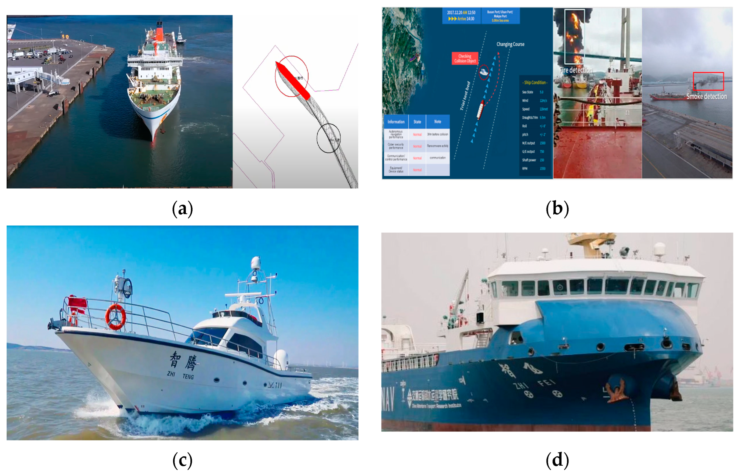
Figure 1. Application of the automatic berthing systems in Asia. (a) Car ferry ‘Sunflower Shiretoko’ [7]. (b) KASS berthing aid system [9]. (c) Training ship ‘ZhiTeng’ [10]. (d) Container ship ‘ZhiFei’ [11].
Jmse 11 01824 g001
Figure 2. Application of the automatic berthing systems in Europe. (a) Car ferry ‘Falco’ [12]. (b) Ferry ‘Folgefonn’ [13]. (c) Container ship ‘YARA Birkeland’ [14]. (d) Volvo Penta docking assistance system [15].
Jmse 11 01824 g002
Figure 3. Workflow of the present paper.
Jmse 11 01824 g003
Figure 4. Overall research objective dependency statistics of the automatic berthing study.
Jmse 11 01824 g004
Figure 5. Timeline distribution of the automatic berthing study.
Jmse 11 01824 g005
Figure 6. Density of safety factor, perception element and technique, and motion control methods in berthing procedure.
Jmse 11 01824 g006aJmse 11 01824 g006b
Figure 7. Density of modeling method in a berthing procedure.
Jmse 11 01824 g007
Figure 8. Overview of maneuverability modeling and prediction methods.
Jmse 11 01824 g008
Figure 10. System-based methods.
Jmse 11 01824 g010
Figure 12. Four-quadrant steerage of propeller and rudder. (a) Propeller four-quadrant performance [67]. (b) Rudder four-quadrant performance [96].
Jmse 11 01824 g012
Figure 13. Water-cushion effects [104].
Jmse 11 01824 g013
Figure 14. External disturbances on ship maneuverability. (A) Wind effect [92]. (B) Current effect [130].
Jmse 11 01824 g014
Figure 15. Auxiliary devices. (a) Side thruster [133]. (b) Pushing of tug [134]. (c) Towing of tug [135].
Jmse 11 01824 g015
Table 1. Application of automatic berthing.
NameTypeDateAffiliationsOverview for Development
AsiaShioji MaruTraining ship
(49 m)
2018MES-S, MOL, TUMST, etc.
Carrying out the tests using a virtual pier.
Sunflower ShiretokoCar ferry
(190 m)
2022MOL Ferry
Tests carried out on the service routes and an actual pier.
MikageContainer ship
(95.4 m, 194TEU)
2022MOL Ferry
Calculating and visually displaying gaps and angles.
/System2020KASS
Berthing aid system.
ZhiTengTraining ship
(21 m)
2019China waterborne transport research institute, etc.
Intelligent situation awareness system;
Autonomous navigation decision-making system;
Autonomous control system.
ZhiFeiContainer ship
(117 m, 300TEU)
2021China waterborne transport research institute, etc.
Three driving modes: manual driving, remote control, and autonomous navigation;
Independent route planning, intelligent collision avoidance, automatic berthing, and disembarking.
EuropeFalcoCar ferry
(53.8 m)
2018Rolls-Royce
Real-time, detailed pictures of surroundings;
50 km remote control.
FolgefonnFerry
(83 m)
2018Wartsilia
Hybrid propulsion;
Automatic wireless charging;
Automatic vacuum mooring;
Automated docking.
YARA BirkelandContainer ship
(117 m, 300TEU)
2021Kongsberg and Yara
Fully electric container feeder;
Remote and unmanned operations.
PENTAFully integrated assisted docking system2021Volvo Penta
Dynamic variable compensating;
Straight line movement without manual compensation;
Stop, slow maneuver functionality;
Rotation around a fixed point;
Micro repositioning and alignment and lateral thrust for lateral docking;
Human–machine interaction.
Table 2. Comparison between conventional MMG model and berthing maneuver model.
IndicesConventional MMG ModelMMG Berthing Maneuver Model
SimilaritiesModeling methodsData-based
System-based
CFD-based
Data-based
System-based
CFD-based
DifferencesHullShip speed0.1 < Fr < 0.3Fr < 0.1
Drifting|β| = [0, 20°]
|r’| = [0, 0.6]
|β| = [0, 180°]
|r’| > 0.6
Rotation rate
Propulsion,
Steerage devices
ThrusterFirst-quadrant inflow angleFour-quadrant inflow angle
RudderSmall resultant inflow angle
High rudder effect
Large resultant inflow angle
Low rudder effect
External disturbanceInsensitiveVulnerable and sensitive
Auxiliary devicesNoneSide thruster, tug, and cable
Table 3. Specifications of various maneuverability prediction methods.
Prediction MethodsAdvantagesDisadvantages
Data-basedFull/model-scale
free-running tests
Reflection of reality
Solid and repeatable
Custom external conditions
Large basin
Physical insight loss
High cost
Captive model tests
High accuracy
Solid and repeatable
Physical insights
Custom external conditions
Massive tests
High sensor precision
High cost
Empirical methods
Quick prediction
High adaptability
Low cost
Insufficient for uncovered hull forms
Physical insight loss
Reliance on mathematical model type
System-basedGrey box
Full/model-scale model
Adaptable to various model types
Low cost
Reliance on an algorithm and data accuracy
Susceptible to noise and external disturbance
Black box
Full/model-scale model
Model-free
Low cost
CFD-basedVirtual captive model tests
Full/model-scale model
Physical insight
Sufficient accuracy
Custom external conditions
Reliance on simulation solver and algorithm accuracy
Requirement of high grid density and computing power
Direct simulation
Integrated method
Quick prediction
Sufficient accuracy
Low cost
Reliance on existing database and algorithm accuracy
High computing power
Table 4. Correspondence of U and np to four-quadrant motion and θp.
MotionQuadrantθpUnp
ahead ship ahead telegraph0–90°aheadnormal
ahead ship astern telegraph90°–180°aheadreverse
astern ship astern telegraph−180°–−90°asternreverse
astern ship ahead telegraph−90°–0asternnormal
Table 5. Overview of propulsion systems.
PropulsionAdvantagesDisadvantages
Conventional propulsion
Inexpensive fuel
Low-cost installation
Long-lasting
Heavy
Valuable space
Pollutant
Azimuth electric diesel
Effective design
Reduced noise and vibration
Redundancy
Efficiency
Maneuverability
Very Expensive
Difficult maintenance
High-quality distributing network
Significant safety level
Mechanically azimuth thruster
Maneuverability
Hardly needs tugs
No need for rudders
Gearbox needed
Expensive
Less efficient than conventional propulsion
Stern-bow thrusters
Assistance with ship turning
Docking without tugs
Only effective under 3 knots of sailing speed
Resistance increase
Water-jet propulsion
Maneuverability
Improved shallow water operation
Reduced noise
Expensive
Less efficient than a propeller at low speed
Risk of intake grill clog.
Water-jet thrusters
Smaller hull penetration
More efficient than bow thrusters at advancing
In need of powerful pumps
Disclaimer/Publisher’s Note: The statements, opinions and data contained in all publications are solely those of the individual author(s) and contributor(s) and not of MDPI and/or the editor(s). MDPI and/or the editor(s) disclaim responsibility for any injury to people or property resulting from any ideas, methods, instructions or products referred to in the content.