
StereoYOLO: A Stereo Vision-Based Method for Maritime Object Recognition and Localization


Abstract
1. Introduction
2. StereoYOLO: A Maritime Target Recognition and Motion State Detection Algorithm
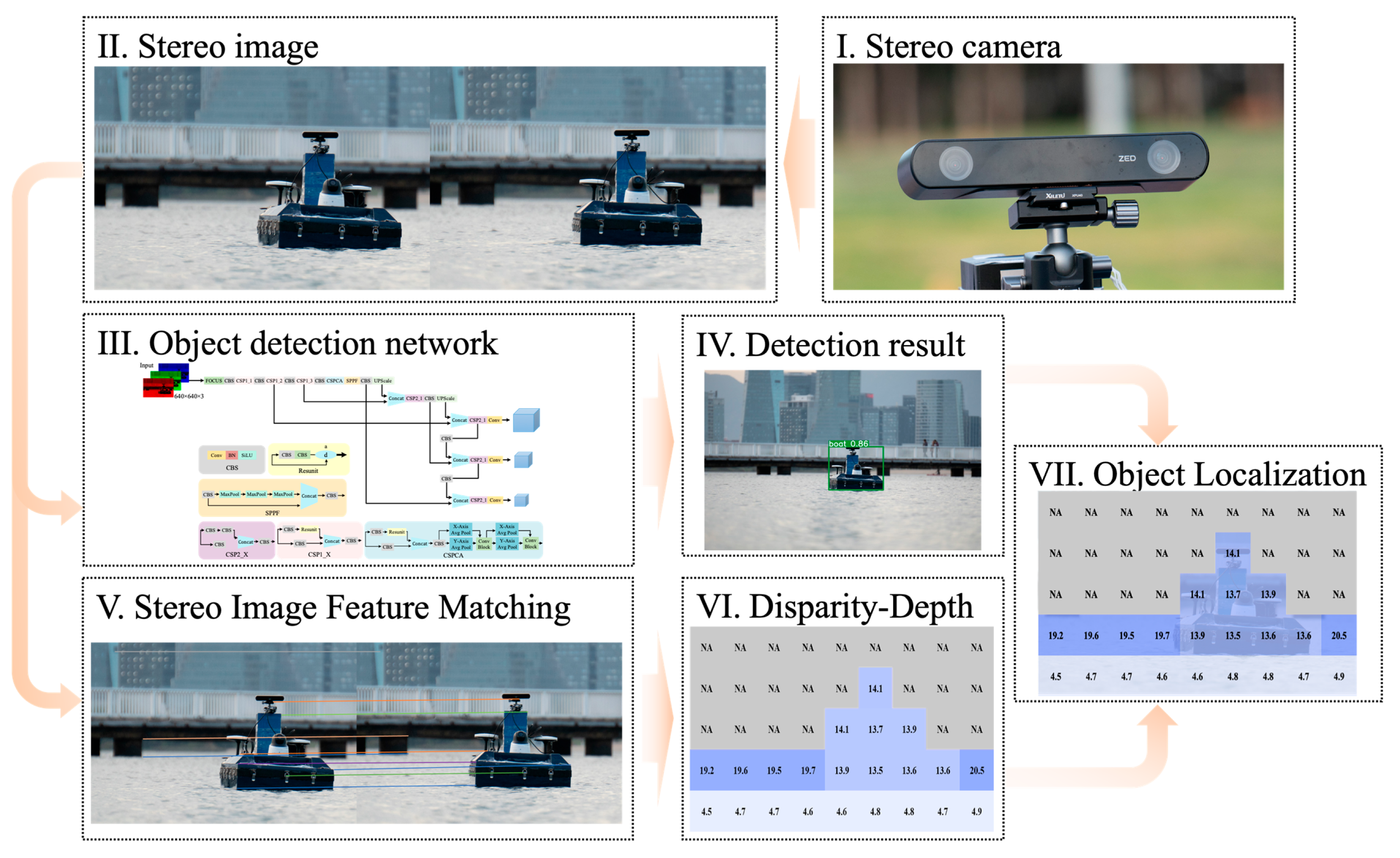
2.1. Target Recognition and Motion State Detection Process
2.2. Stereo Vision Model
2.3. Improved Maritime Target Detection Algorithm
2.3.1. Algorithm Framework
2.3.2. Backbone Network
2.3.3. Feature Extraction Network
2.3.4. Detection Head
2.3.5. Loss Function
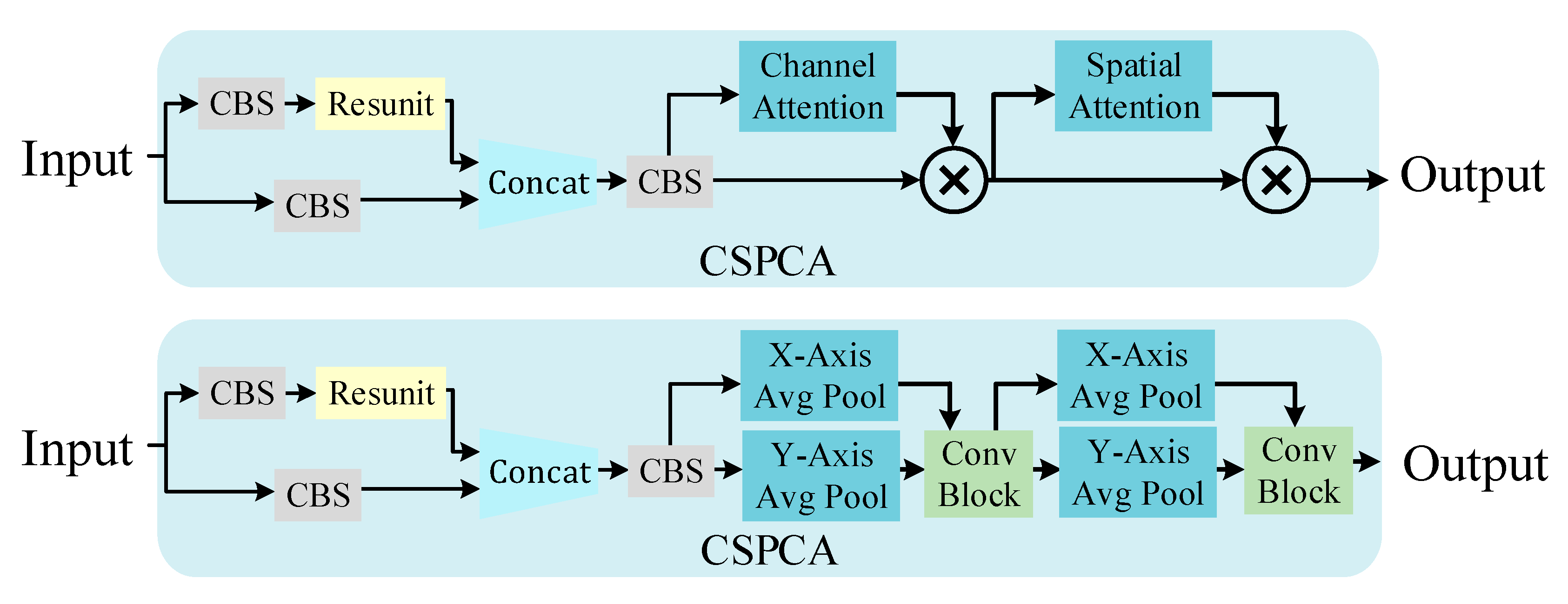
2.3.6. Attention Mechanism-Based Maritime Target Detection Algorithm
2.3.7. Experimental Platform
3. Model Training and Experiment
3.1. Model Training and Evaluation Metrics
3.2. Simulation Experiment Analysis of Ship Target Detection Based on CBAM Improvement
3.3. Simulation Analysis of Ship Target Detection with Improved Maritime Target Detection Algorithm Based on Multiple Attention Mechanisms
3.4. Experiment on Ship Trajectory Detection Method Fused with Stereo Vision
4. Conclusions
- The CBAM attention mechanism-improved StereoYOLO algorithm has increased target recognition accuracy compared to the original algorithm while keeping the computational requirements almost unchanged. Among them, adding the attention module after the CSP1_4 layer achieves the highest accuracy improvement for maritime target recognition tasks, reaching 1.71%. In subsequent multiple tests, the improved algorithm achieved a 2.07% increase in mAP50 performance compared to the original YOLOv5;
- The CA attention-based improved StereoYOLO algorithm, which performs feature pooling operations separately for the h-direction and w-direction, has a higher detection accuracy compared to other attention algorithms, with a mAP50 accuracy improvement of 5.23% compared to the pre-improvement algorithm;
- Enhancements to the distance measurement algorithm have significantly increased the robustness of positioning accuracy in maritime target recognition tasks, especially under the conditions of a ship’s angular oscillations in three dimensions. This improvement becomes evident when detecting the same target at consistent distances, where the refined algorithm has notably reduced the coefficient of variation in data deviation, attributable to the ship’s roll, pitch, and yaw movements, from 9.59% to 3.47%;
- The SGBM feature point matching algorithm used in the algorithm has limitations. The use of stereo transformer and other depth neural network-based multi-view vision algorithms to improve target positioning accuracy will become the focus of subsequent research.
Author Contributions
Funding
Institutional Review Board Statement
Informed Consent Statement
Data Availability Statement
Conflicts of Interest
Nomenclature
| AI | Artificial Intelligence |
| AIS | Automatic Identification System |
| SVM | Support Vector Machine |
| NPU | Neural Processing Unit |
| CNN | Convolutional Neural Network |
| FPN | Feature Pyramid Network |
| CBAM | Convolutional Block Attention Module |
| CA | Coordinate Attention Module |
| YOLO | You Only Look Once |
| SGBM | Semi-Global Block Matching |
| mAP | mean Average Precision |
| IoU | Intersection over Union |
| GIoU | Generalized Intersection over Union |
| TFLOPS | Tera Floating Point Operations Per Second |
| GFLOP | Giga Floating Point Operations |
| ⊗ | tensor inner product |
References
- Sun, S.; Lyu, H.; Dong, C. AIS Aided Marine Radar Target Tracking in a Detection Occluded Environment. Ocean Eng. 2023, 288 Pt 2, 116133. [Google Scholar] [CrossRef]
- Nudd, G.; Nygaard, P. Demonstration of a C.C.D. Image Processor for Two-Dimensional Edge Detection. Electron. Lett. 1978, 14, 83–85. [Google Scholar] [CrossRef]
- Canny, J. A Computational Approach to Edge Detection. IEEE Trans. Pattern Anal. Mach. Intell. 1986, PAMI-8, 679–698. [Google Scholar] [CrossRef]
- Dalal, N.; Triggs, B. Histograms of Oriented Gradients for human Detection. In Proceedings of the 2005 IEEE Computer Society Conference on Computer Vision and Pattern Recognition (CVPR’05), San Diego, CA, USA, 20–25 June 2005; Volume 1, pp. 886–893. [Google Scholar] [CrossRef]
- Lowe, D. Distinctive Image Features from Scale-Invariant Keypoints. Int. J. Comput. Vis. 2004, 60, 91–110. [Google Scholar] [CrossRef]
- Dosovitskiy, A.; Brox, T. Inverting Visual Representations with Convolutional Networks. In Proceedings of the 2016 IEEE Conference on Computer Vision and Pattern Recognition (CVPR), Las Vegas, NV, USA, 27–30 June 2016; pp. 4829–4837. [Google Scholar] [CrossRef]
- Zhang, T.; Zheng, W.; Cui, Z.; Zong, Y.; Yan, J.; Yan, K. A Deep Neural Network-Driven Feature Learning Method for Multi-view Facial Expression Recognition. IEEE Trans. Multimed. 2016, 18, 2528–2536. [Google Scholar] [CrossRef]
- Krizhevsky, A.; Sutskever, I.; Hinton, G.E. ImageNet Classification with Deep Convolutional Neural Networks. In Proceedings of the 25th International Conference on Neural Information Processing Systems—Volume 1 (NIPS’12), Lake Tahoe, CA, USA, 3–6 December 2012; Curran Associates Inc.: Red Hook, NY, USA, 2012; pp. 1097–1105. [Google Scholar]
- Kalake, L.; Wan, W.; Hou, L. Analysis Based on Recent Deep Learning Approaches Applied in Real-Time Multi-Object Tracking: A Review. IEEE Access 2021, 9, 32650–32671. [Google Scholar] [CrossRef]
- Liu, Z.; Waqas, M.; Yang, J.; Rashid, A.; Han, Z. A Multi-Task CNN for Maritime Target Detection. IEEE Signal Process. Lett. 2021, 28, 434–438. [Google Scholar] [CrossRef]
- Liu, K.; Yu, S.; Liu, S. An Improved InceptionV3 Network for Obscured Ship Classification in Remote Sensing Images. IEEE J. Sel. Top. Appl. Earth Obs. Remote Sens. 2020, 13, 4738–4747. [Google Scholar] [CrossRef]
- Hu, Y.; Yang, J.; Chen, L.; Li, K.; Sima, C.; Zhu, X.; Chai, S.; Du, S.; Lin, T.; Wang, W.; et al. Planning-Oriented Autonomous Driving. In Proceedings of the 2023 IEEE/CVF Conference on Computer Vision and Pattern Recognition (CVPR), Vancouver, BC, Canada, 17–24 June 2023; pp. 17853–17862. [Google Scholar] [CrossRef]
- Li, P.; Qin, T. Stereo Vision-Based Semantic 3d Object and Ego-Motion Tracking for Autonomous Driving. In Proceedings of the European Conference on Computer Vision (ECCV), Munich, Germany, 8–14 September 2018; pp. 646–661. [Google Scholar]
- Li, P.; Chen, X.; Shen, S. Stereo R-CNN Based 3d Object Detection for Autonomous Driving. In Proceedings of the IEEE/CVF Conference on Computer Vision and Pattern Recognition, Long Beach, CA, USA, 15–20 June 2019; pp. 7644–7652. [Google Scholar]
- Shi, Y.; Guo, Y.; Mi, Z.; Li, X. Stereo CenterNet-based 3D Object Detection for Autonomous Driving. Neurocomputing 2022, 471, 219–229. [Google Scholar] [CrossRef]
- Woo, S.; Park, J.; Lee, J.Y.; Kweon, I.S. Cbam: Convolutional Block Attention Module. In Proceedings of the European Conference on Computer Vision (ECCV), Munich, Germany, 8–14 September 2018; pp. 3–19. [Google Scholar]
- Hou, Q.; Zhou, D.; Feng, J. Coordinate Attention for Efficient Mobile Network Design. In Proceedings of the IEEE/CVF Conference on Computer Vision and Pattern Recognition, Nashville, TN, USA, 19–25 June 2021; pp. 13713–13722. [Google Scholar]
- Wang, Y.; Zhang, J.; Kan, M.; Shan, S.; Chen, X. Self-Supervised Equivariant Attention Mechanism for Weakly Supervised Semantic Segmentation. In Proceedings of the IEEE/CVF Conference on Computer Vision and Pattern Recognition, Seattle, WA, USA, 14–19 June 2020; pp. 12275–12284. [Google Scholar]
- Li, B.; Xie, X.; Wei, X.; Tang, W. Ship Detection and Classification from Optical Remote Sensing Images: A Survey. Chin. J. Aeronaut. 2021, 34, 145–163. [Google Scholar] [CrossRef]
- Wang, B.; Jiang, P.; Gao, J.; Huo, W.; Yang, Z.; Liao, Y. A Lightweight Few-Shot Marine Object Detection Network for Unmanned Surface Vehicles. Ocean Eng. 2023, 277, 114329. [Google Scholar] [CrossRef]
- Liu, L.; Fu, L.; Zhang, Y.; Ni, W.; Wu, B.; Li, Y.; Shang, C.; Shen, Q. CLFR-Det: Cross-Level Feature Refinement Detector for Tiny-Ship Detection in SAR Images. Knowl. Based Syst. 2024, 284, 111284. [Google Scholar] [CrossRef]
- Lin, C.; Wu, C.; Zhou, H. Multi-Visual Feature Saliency Detection for Sea-Surface Targets through Improved Sea-Sky-Line Detection. J. Mar. Sci. Eng. 2020, 8, 799. [Google Scholar] [CrossRef]
- Patel, K.; Bhatt, C.; Mazzeo, P. Deep Learning-Based Automatic Detection of Ships: An Experimental Study Using Satellite Images. J. Imaging 2022, 8, 182. [Google Scholar] [CrossRef] [PubMed]
- Xiong, B.; Sun, Z.; Wang, J.; Leng, X.; Ji, K. A Lightweight Model for Ship Detection and Recognition in Complex-Scene SAR Images. Remote Sens. 2022, 14, 6053. [Google Scholar] [CrossRef]
- Kizilkaya, S.; Alganci, U.; Sertel, E. VHRShips: An Extensive Benchmark Dataset for Scalable Deep Learning-Based Ship Detection Applications. ISPRS Int. J. Geo-Inf. 2022, 11, 445. [Google Scholar] [CrossRef]
- Cheng, S.; Zhu, Y.; Wu, S. Deep Learning Based Efficient Ship Detection from Drone-Captured Images for Maritime Surveillance. Ocean. Eng. 2023, 285 Pt 2, 115440. [Google Scholar] [CrossRef]
- Zhang, Q.; Huang, Y.; Song, R. A Ship Detection Model Based on YOLOX with Lightweight Adaptive Channel Feature Fusion and Sparse Data Augmentation. In Proceedings of the 2022 18th IEEE International Conference on Advanced Video and Signal Based Surveillance (AVSS), Madrid, Spain, 29 November–2 December 2022; pp. 1–8. [Google Scholar] [CrossRef]
- Thombre, S.; Zhao, Z.; Ramm-Schmidt, H.; Vallet Garcia, J.M.; Malkamaki, T.; Nikolskiy, S.; Hammarberg, T.; Nuortie, H.; Bhuiyan, M.Z.H.; Sarkka, S.; et al. Sensors and AI Techniques for Situational Awareness in Autonomous Ships: A Review. IEEE Trans. Intell. Transp. Syst. 2022, 23, 64–83. [Google Scholar] [CrossRef]
- Xu, S.; Jiang, Y.; Li, Y.; Liu, S.; Ding, S.; Ma, D.; Qi, H.; Zhang, W. A Stereo Vision Localization Method for Autonomous Recovery of Autonomous Underwater Vehicle. J. Harbin Eng. Univ. 2022, 43, 1084–1090. [Google Scholar]
- He, H.; Wa, N. Monocular Visual Servo-Based Stabilization Control of Underactuated Unmanned Surface Vehicle. Chin. J. Ship Res. 2022, 17, 166–174. [Google Scholar]
- Zhu, S.; Li, C.; Change Loy, C.; Tang, X. Face Alignment by Coarse-to-Fine Shape Searching. In Proceedings of the IEEE Conference on Computer Vision and Pattern Recognition, Boston, MA, USA, 7–12 June 2015; pp. 4998–5006. [Google Scholar]
- Chang, A.X.; Funkhouser, T.; Guibas, L.; Hanrahan, P.; Huang, Q.; Li, Z.; Savarese, S.; Savva, M.; Song, S.; Su, H.; et al. Shapenet: An Information-Rich 3D Model Repository. arXiv 2015, arXiv:1512.03012. [Google Scholar]
- Hirschmuller, H. Stereo Processing by Semiglobal Matching and Mutual Information. IEEE Trans. Pattern Anal. Mach. Intell. 2008, 30, 328–341. [Google Scholar] [CrossRef] [PubMed]
- Barnell, M.; Raymond, C.; Smiley, S.; Isereau, D.; Brown, D. Ultra Low-Power Deep Learning Applications at the Edge with Jetson Orin AGX Hardware. In Proceedings of the 2022 IEEE High Performance Extreme Computing Conference (HPEC), Waltham, MA, USA, 23–27 September 2022; pp. 1–4. [Google Scholar] [CrossRef]
- Shao, Z.; Wu, W.; Wang, Z.; Du, W.; Li, C. SeaShips: A Large-Scale Precisely-Annotated Dataset for Ship Detection. IEEE Trans. Multimed. 2018, 20, 2593–2604. [Google Scholar] [CrossRef]


| Platform Information | Development Platform | Embedded Platform |
|---|---|---|
| CPU | 8 Core Intel i7-10700F@2.9GHz | 12 Core Arm Cortex-A78AE@1.3GHz |
| RAM | 64 GB | 32 GB |
| GPU | NVIDIA RTX A4000 | 2048 Core NVIDIA Ampere GPU |
| FP32 Performance | 19.2 TFLOPS | 5.32 TFLOPS |
| Operation System | Windows10 21H2 | Ubuntu20.04 |
| Power Consumption | 300 W | 60 W |
| resolution | 640 × 640 |
| maximum epoch | 100 |
| optimizer | Adam |
| batch Size | 16 |
| Training data | 6300 |
| Val data | 700 |
| pretrained | No |
| Modified Module | mAP50/% |
|---|---|
| CSP1_1 | 77.69 |
| CSP1_4 | 78.70 |
| CSP1_1/CSP1_2/CSP1_3/CSP1_4 | 78.09 |
| YOLOv5s | 76.99 |
| Experiment ID | Attention Plugins | FLOPs | mAP50/% |
|---|---|---|---|
| 1 | None | 15.8G | 77.48 |
| 2 | None | 15.8G | 75.35 |
| 3 | None | 15.8G | 76.20 |
| 4 | None | 15.8G | 76.10 |
| 5 | None | 15.8G | 76.25 |
| 6 | CA | 15.9G | 77.04 |
| 7 | CA | 15.9G | 77.66 |
| 8 | CA | 15.9G | 78.80 |
| 9 | CA | 15.9G | 86.14 |
| 10 | CA | 15.9G | 87.86 |
| 11 | CBAM | 15.9G | 80.31 |
| 12 | CBAM | 15.9G | 76.53 |
| 13 | CBAM | 15.9G | 77.87 |
| 14 | CBAM | 15.9G | 77.22 |
| 15 | CBAM | 15.9G | 79.78 |
| Experiment ID | Detect Distance/m | Actual Distance/m |
|---|---|---|
| 1 | 2.306 | 2.253 |
| 2 | 4.35 | 4.6 |
| 3 | 5.3 | 5.8 |
| 4 | 8.9 | 10.14 |
| 5 | 11.41 | 10.654 |
| 6 | 8.2 | 7.616 |
| 7 | 5.6 | 5.519 |
| 8 | 3.5 | 3.467 |
Disclaimer/Publisher’s Note: The statements, opinions and data contained in all publications are solely those of the individual author(s) and contributor(s) and not of MDPI and/or the editor(s). MDPI and/or the editor(s) disclaim responsibility for any injury to people or property resulting from any ideas, methods, instructions or products referred to in the content. |
© 2024 by the authors. Licensee MDPI, Basel, Switzerland. This article is an open access article distributed under the terms and conditions of the Creative Commons Attribution (CC BY) license (https://creativecommons.org/licenses/by/4.0/).
Share and Cite
Shang, Y.; Yu, W.; Zeng, G.; Li, H.; Wu, Y. StereoYOLO: A Stereo Vision-Based Method for Maritime Object Recognition and Localization. J. Mar. Sci. Eng. 2024, 12, 197. https://doi.org/10.3390/jmse12010197
Shang Y, Yu W, Zeng G, Li H, Wu Y. StereoYOLO: A Stereo Vision-Based Method for Maritime Object Recognition and Localization. Journal of Marine Science and Engineering. 2024; 12(1):197. https://doi.org/10.3390/jmse12010197
Chicago/Turabian StyleShang, Yifan, Wanneng Yu, Guangmiao Zeng, Huihui Li, and Yuegao Wu. 2024. "StereoYOLO: A Stereo Vision-Based Method for Maritime Object Recognition and Localization" Journal of Marine Science and Engineering 12, no. 1: 197. https://doi.org/10.3390/jmse12010197
APA StyleShang, Y., Yu, W., Zeng, G., Li, H., & Wu, Y. (2024). StereoYOLO: A Stereo Vision-Based Method for Maritime Object Recognition and Localization. Journal of Marine Science and Engineering, 12(1), 197. https://doi.org/10.3390/jmse12010197