Article

Distribution Patterns and Genesis of Geological Fractures/Microfaults in the Qiongdongnan Basin, North of the South China Sea

1
School of Petroleum Engineering, Guangdong University of Petrochemical Technology, Maoming 525000, China
2
Zhanjiang Company, CNOOC Limited, Zhanjiang 524057, China
3
Hainan Company, CNOOC Limited, Haikou 570100, China
*
Author to whom correspondence should be addressed.
J. Mar. Sci. Eng. 2024, 12(1), 37; https://doi.org/10.3390/jmse12010037
Submission received: 6 November 2023 / Revised: 18 December 2023 / Accepted: 20 December 2023 / Published: 22 December 2023
(This article belongs to the Special Issue Petroleum and Gas Hydrate Exploration and Marine Geology)

Abstract

:
The Qiongdongnan Basin (QDNB), located in the north of the South China Sea, is a Cenozoic rift basin with abundant oil and gas resources. Large flake hydrates have been found in the core fractures of Quaternary formations in the deep-water depression of the QDNB. In order to understand the spatial distribution patterns of these fractures, their geneses in sedimentary basins, and their influences on gas migration and accumulation, such fractures have been observed using high-resolution 3D seismic images and visualization techniques. Four types of fractures and their combinations have been identified, namely bed-bounded fractures/microfaults, unbounded fractures, fracture bunches, and fracture clusters. Bed-bounded fractures/microfaults are mainly short and possess high density; they have developed in mass transport depositions (MTDs) or Meishan and Sanya Formations. The unbounded fractures/microfaults that occur in Miocene–Pliocene formations are mainly long and discrete, and are dominantly caused by strong tectonic movements, the concentration of stress, and sustained intense overpressure. The fracture bunches and fracture clusters that occur in Oligocene–Early Miocene formations have commonly developed with the accumulation of large numbers of fractures and may be related to the release of pressure, diapirs, and basement fault blocks (228.9 ± 1 Ma). In this study, six fluid charging or leakage models are proposed based on distinct fracture types, assuming the uniform conductivity of each fracture. In a 3D space view, a vertical decrease in the fracture scale (number or density) will more likely result in gas supply than dispersion, thus promoting the accumulation of gas in the reservoirs. Nevertheless, the fractures above the Bottom Simulating Reflect (BSR)/seismic anomaly are excessively developed, and bed-bounded fractures within a particular layer, such as MTDs, can easily cause seabed leakage. These results are useful for explaining the vertical migration of gas/fluids in areas and formations with less developed gas chimneys, faults, diapirs, and other structures, particularly in post-rifting basins.

1. Introduction

Fractures/microfaults in petroliferous basins are fluid transport systems that are easily overlooked in contrast to faults with major displacement, diapir structures [1,2], gas chimneys, and slump structures [3]; this is because the displacement of a single fracture or microfault is usually smaller than that of a fault, and cannot provide sufficient oil and gas charging efficiency for conventional reservoirs.
However, in recent years, multiple studies have shown that fractures/microfaults are important pathways for fluid migration and accumulation regarding the formation of shallow gas reservoirs and hydrates [3,4,5,6,7]. In deep-water basins, the transport of gas into and through the Gas Hydrate Stability Zone (GHSZ) via fractures has been observed through drilling in fine-grained successions, and is widely considered useful as a model with which to explain the leakage of fluids [5,8]. In recent years, numerous nodular and sheet-like hydrates that cause fractured reservoirs have been found in the north of the South China Sea [9]; thus, their characteristics, including their composition, distribution, spacing, density, and length, are of great interest to many scholars [10].
In the past, a large number of field outcrop descriptions have revealed the existence of fractures in secondary structures near the main fault and under the influence of regional tectonic stresses [11]. Research has confirmed that, in some cases, secondary fractures can link originally unconnected faults. Verified using the fracture networks observed in a natural outcrop, models able to describe the key information pertaining to complex fractures, such as the fracture center, length, and orientation distributions, have been proposed [12]. Based on the field outcrop, the fracture-aperture-sized frequency, spatial distribution, and growth processes in bed-bounded and unbounded fractures have been observed and quantitatively studied [13]. This work provides a good reference for the classification of complex fracture systems; however, due to the lack of effective geological outcrops, this work cannot be applied to deep-sea basins. Moreover, fractures in the field are mainly caused by tectonic stress, while fractures in deep-sea basins can be caused by overpressure and other factors.
With the development of extensive offshore drilling [14,15], computer techniques [16] and the acquisition of high-resolution seismic data [17], the spatial distribution structure of fractures/microfaults can be studied via core drilling, computer modeling, and seismic imaging.
It is far from sufficient to determine the fracture characteristics of the exploration area via drilling and neural network simulation. Because the core drilling emphasizes the fracture structure of a single point, it cannot replace the fracture distribution in the whole basin. The simulation of discontinuous discrete fractures using a computer neural network is constrained by the regional tectonic stress field and fault system, and the geological body is assumed to be homogeneous. This creates significant uncertainty in the simulation results [18,19]. In fact, due to the heterogeneity of geological bodies, fractures/microfaults are not uniformly distributed in the geological space. In other words, the generation of fractures is related to special geological processes, and specific patterns of fractures or fracture combinations are generated in specific geological formations and have their own unique geological origin. Some fractures are isolated, some are clustered, and some are only distributed in specific strata.
In recent decades, seismic data combined with core and optical televiewer images have been used to analyze the structure and degree of development of fractures in sedimentary basins [17,20]. When studying the effect of fractures in lower Tertiary sandstone on the leakage of fluid in the North Sea Basin, Løseth et al. [21,22,23] identified the vertical discontinuity zone in seismic sections and discussed its relationship with seismic anomalies. However, the authors did not create a classification system or study the genetic environment. Navalpakam et al. [24] took this work a step further, and found that relatively weak Bottom Simulating Reflectors (BSRs) on the Hikurangi margin are related to the nature of the gas distribution within the pores and fractures of the sediments. Rubin [25] also found that tensile fracture occurs when the rock is confined at a high pressure. All these results have linked seismic imaging with the geological interpretation well.
In the Qiongdongnan Basin (QDNB), the overlying Tertiary layer on the Indosinian granite basement block produces numerous fractures under the action of transverse bending folding [7]. Since the late Oligocene, the basin has developed high levels of overpressure, a wide range of fluid activities have pierced the deep strata so as to overlay sediments, and a large number of fractures have developed [26]. The special geological processes that occur in shallow layers, such as submarine landslides and differential subsidence, are also important factors in the production of fractures [27,28,29,30].
Therefore, the spatial distribution of fractures within a specific study area can be observed and classified via seismic means, and their geological genesis can be studied; this is conducive to the study of the fracture transport and leakage system, the selection and judgment of advantageous pathways for the migration of hydrocarbons, and the prediction of natural gas reservoirs and hydrates. At the same time, this spatial distribution can enable us to understand the effects of fractures on the reservoir behavior and their impact on the production of hydrocarbons; therefore, numerical simulations considering various approaches have been carried out. On the basis of a quantitative description of the fracture parameters, and in combination with the current knowledge of stress, the porosity and permeability of different assemblages of fractures can be calculated using the Monte Carlo method [31].
This paper aims to investigate the distribution of seismic data and the genesis of fractures/microfaults in the QDNB. The reflection characteristics, distribution of seismic sections, and their role in transporting gas to the reservoirs of various fractures are thus described. Gas migration and accumulation models concerning the various distribution characteristics of fractures are proposed.

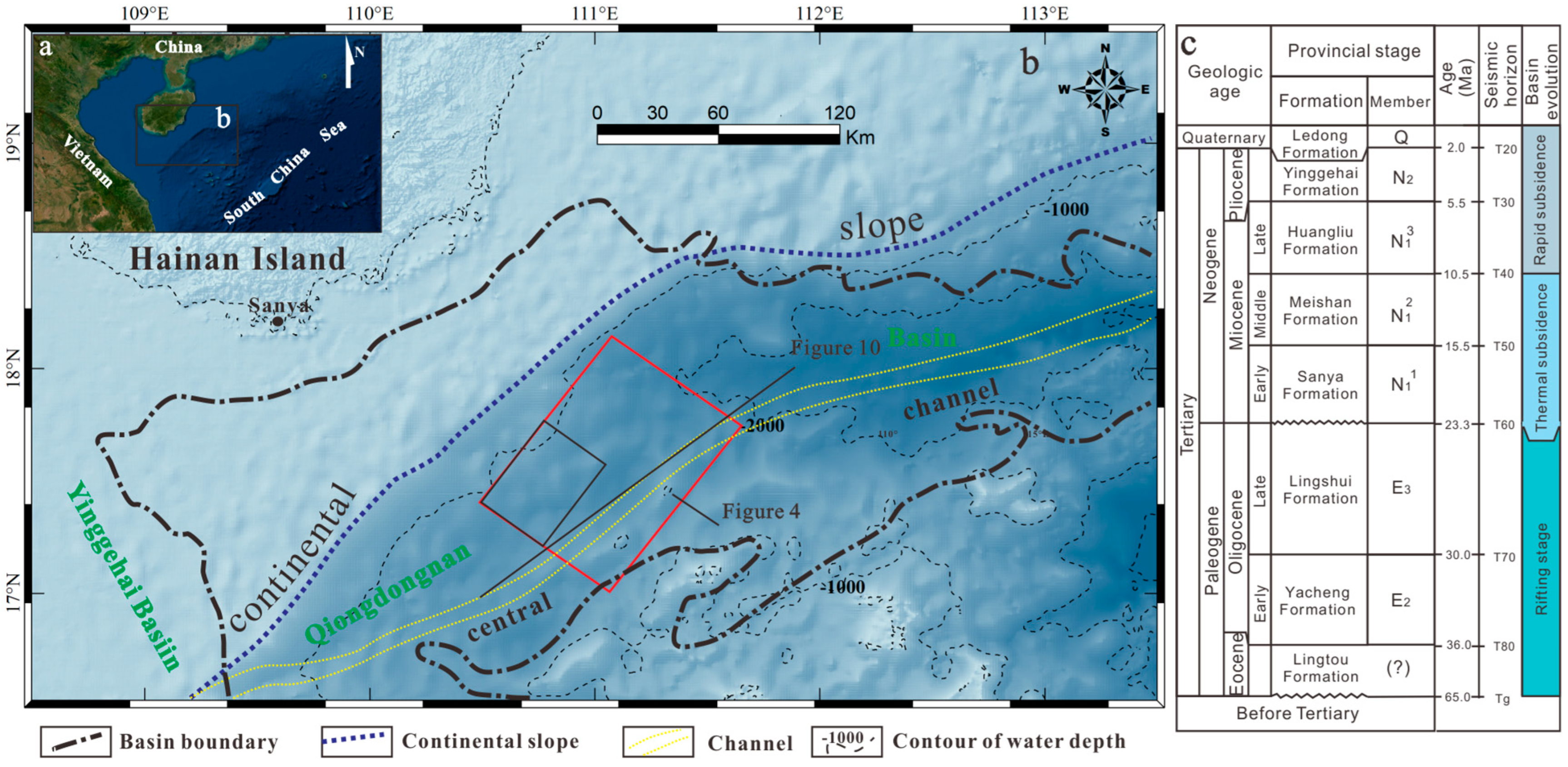
2. Geological Setting

The QDNB is a Cenozoic sedimentary basin located on the northern continental margin of the South China Sea (SCS) (Figure 1a,b); it trends NE-SW and has a total area of approximately 7 × 10⁴ km2 [32]. The QDNB has undergone the syn-rift stage (Eocene–Oligocene) and post-rift stage (Neogene–Quaternary) (Figure 1c) [33]. The rifting stage presented more fault activity than the post-rifting stage [34], and the post-rifting stage was mainly characterized by thermal subsidence and rapid subsidence. During this period, no obvious fault activity developed. Sediments of this period primarily comprise continental or transcontinental facies [35]. The post-rift sediments mainly comprise marine deposits. The Sanya and Meishan Formations deposited a set of shallow to neritic mudstones that host hydrocarbons in the area [35]. The Huangliu and Yinggehai Formations were formed in shallow to semi-deep environments and mainly developed deltas, turbidite rocks [7,36], submarine fans, and central channels (Figure 1b). Since the Pliocene, the dominant sediments have been deep ocean siltstone, argillaceous siltstone, and mudstone [37,38].
A typical continental shelf, continental slope, and deep-water basin structure characterize the QDNB, which has a maximum water depth exceeding 2500 m [32]. The BSR/shallow seismic anomaly corresponds to a two-way seismic reflection time of approximately 1.6–3.0 s. Since the deposition of the Huangliu Formation (T30–T40) (Figure 1c), there has been no basin-controlling fault activity, so terrigenous clastic progradation to the sea has been the main driver of slope development. This constant movement led to multiple stages of landslides in the Miocene [39]. Furthermore, the basin experienced a period of post-rift rapid thermal subsidence during the Miocene, generating overpressurization phenomena [20], diapirs, gas chimneys, and hydraulic fractures. These basin conditions were favorable for the migration and accumulation of complex oil and gas. The Huangliu Formation in the deep-water basin has been discovered to contain over 200 billion cubic meters of natural gas reserves [40]. It has been confirmed that diapirs and fractures that are formed by the presence of abnormally high pressures at depth are efficient conduits for fluid migration [41,42,43].
In 2015, the Haima Cold Seep in the west of the QDNB was discovered by the Guangzhou Marine Geological Survey (GMGS). In 2018, another drilling project that aimed to address the bottom simulating reflector (BSR) in the eastern area of the QDNB was performed [9,44]. The BSR drilled at Site GMGS5-W9-2018 runs perpendicular to the ocean floor and rises around 4 km above the gas chimney, with numerous fractures present above and below.
The findings of Liang [9], as well as those confirmed by Wei et al. [45], indicate that the gas chimney serves as a major and lower pathway for the migration of hydrocarbons. Meanwhile, fractures at the top of the gas chimney serve as upper leakage systems and reservoirs for gas hydrates. Furthermore, the high saturation of the hydrates in well W9 corresponds to higher fracture densities and log resistivities, thus suggesting that the degree of fracture development affects the movement and accumulation of gas.

3. Data and Methods

This work was performed at the location in which hydrates were discovered by the GMGS (Figure 1b). The drill results obtained from GMGS5-W9-2018 and the 3D seismic datasets were used for this work. The strata on top of the Huangliu Formation (T40) have a vertical resolution of approximately 30–35 Hz and a horizontal resolution of 12.5 m (track pitch) for seismic activity (Figure 2B). In Table 1, the detailed parameters of the seismic and well data are listed.
According to the vertical velocity of the seismic waves in this area, calculated to be 2600–2800 m/s, and the main frequency of 30 Hz, the minimum layer thickness able to recognized by seismic waves is λ/4, i.e., h = V/4f. Regarding the density and gas in the pore space, a negative reflection in the BSR is observed on the seafloor, implying that the seafloor’s density should be positively relative to seawater. The BSR range (Figure 2A) was implemented according to the BSR observed in well W9 and the polarity reversal of the seabed reflection (Figure 2B). Hydrate samples were also obtained at GMGS5-W9-2018 (Figure 2C–E); therefore, due to the relationship between fractures and the BSR, the migration of gas to the reservoir via fractures can be observed.
Some seismic anomalies can be attributed to the presence of sand bodies, hydrates, and gas reservoirs near the BSR range, and the fluid charging processes are likely the same. Therefore, a horizontal seismic section close to the BSR is selected as a reference surface to expand the range of the BSR and explore the relationship between fractures and these seismic anomalies. Prior to the detection of fractures, two reference surfaces were selected, and the corresponding seismic depths were moved down by 10 ms and up by 10 ms along the top surface of the BSR in Figure 2B, respectively. These are only reference planes that follow the BSR or the anomaly, and their planal positions are referred to in Figure 1b.
The approach utilized for the fracture detection employs a collection of directive, multi-trace seismic properties, as well as a supervised neural network [18], which has been tested on large data sets from the Central North Sea, Persian Gulf, and Taranaki basin, and recently in the QDNB [27,46,47]. Two-way travel time (TWT) seismic data are used in this study, because although depth data can more accurately reflect the true shape of a structure, it has limited influence on the distribution type, density, and relative size of the fracture. The coherent volume was extracted in 3 × 3 steps for the characterization fractures. After the volume was loaded and hollowed out, the surrounding coherence information was filtered out before the volume element transparency was adjusted and corrected to obtain the final dataset. In cases in which fractures have developed on a large scale, have a characteristic distribution pattern, and cut through the BSR range, it is unlikely that gas migrates and accumulates along them.

4. Spatial Distribution of Geological Fractures

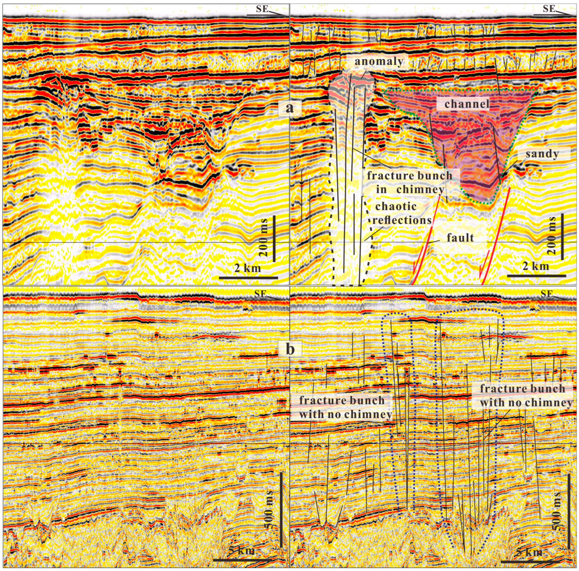
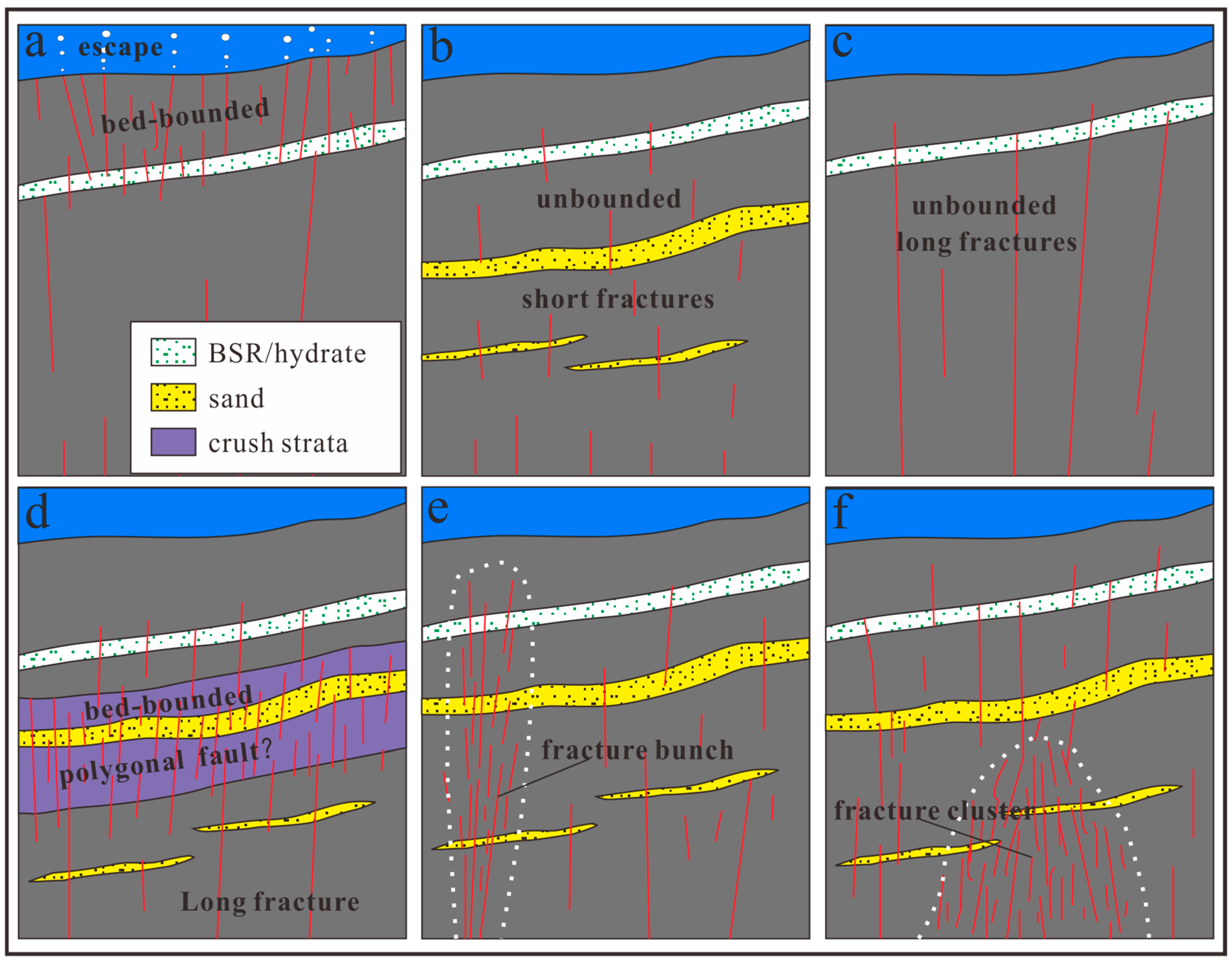
4.1. Definitions of Fractures/Microfaults of Different Patterns in Seismic Sections

Based on the distribution patterns in the seismic images of fractures and the intersectional relationships between fractures and strata, four types of fractures were identified: bed-bounded fractures/microfaults, unbounded fractures, fracture bunches, and fracture clusters. These fractures/microfaults have corresponding response characteristics in the seismic data (Figure 3, Figure 4, Figure 5, Figure 6 and Figure 7).
Bed-bounded fractures/microfaults are commonly discrete short fractures that appear in a certain stratum, as fractures do not cross from one given bed to another [48,49]. While they can be dispersed in thick strata, according to Figure 3, they can also develop in thin sedimentary layers; for instance, these short fractures are usually densely developed in sedimentary layers [9]. However, each fracture usually cuts through only 5–6 seismic events and cannot connect the source rock with reservoirs. The actual layer thickness of a single seismic event is approximately 21–23 m according to the calculated vertical velocity of seismic waves and the main frequency in this area [27]. Therefore, the vertical lengths of short fractures within the formation are generally less than 100 m, and may only be a few dozen meters or less.
Unbounded (non-bed bounded) fractures are commonly much longer than bed-bounded fractures/microfaults, and cross from one given bed to another [14,48]. For example, these fractures cut vertically through the entire strata of the Huangliu formation and even extend deep into the Meishan and Sanya formations’ hydrocarbon source rocks (Figure 1c), with an extended length of hundreds or even thousands of meters (Figure 4 and Figure 5).
Fracture bunches are composed of fractures of a similar size that are bundled in a regular, condensed manner. These fractures increase the size of the fracture aggregate and form a bundle-like structure (Figure 6). Because tubular fracture bunches have a greater width than a long independent fracture, they are more conducive to the transport of gas–hydrate fluids.
A fracture cluster combines long and short fractures or fracture bunches with irregular contours, usually including cone, mushroom, and spindle shapes. Figure 8 shows that fracture clusters most often develop in deep stratigraphic space. On a seismic profile, a fracture cluster mainly presents as a fuzzy zone, with disorderly and discontinuous reflection features; these are the internal responses of the fracture-intensive area (Figure 7). In addition to the fluid that affects the seismic pull-down, Liang et al. [9] note that the occurrence of reflection events in gas chimneys can also be the result of faults or fractures that are difficult to observe. In proximity to the gas anomaly, some normal faults are usually observed.

4.2. Observation and Description of Fractures in the Seismic Section

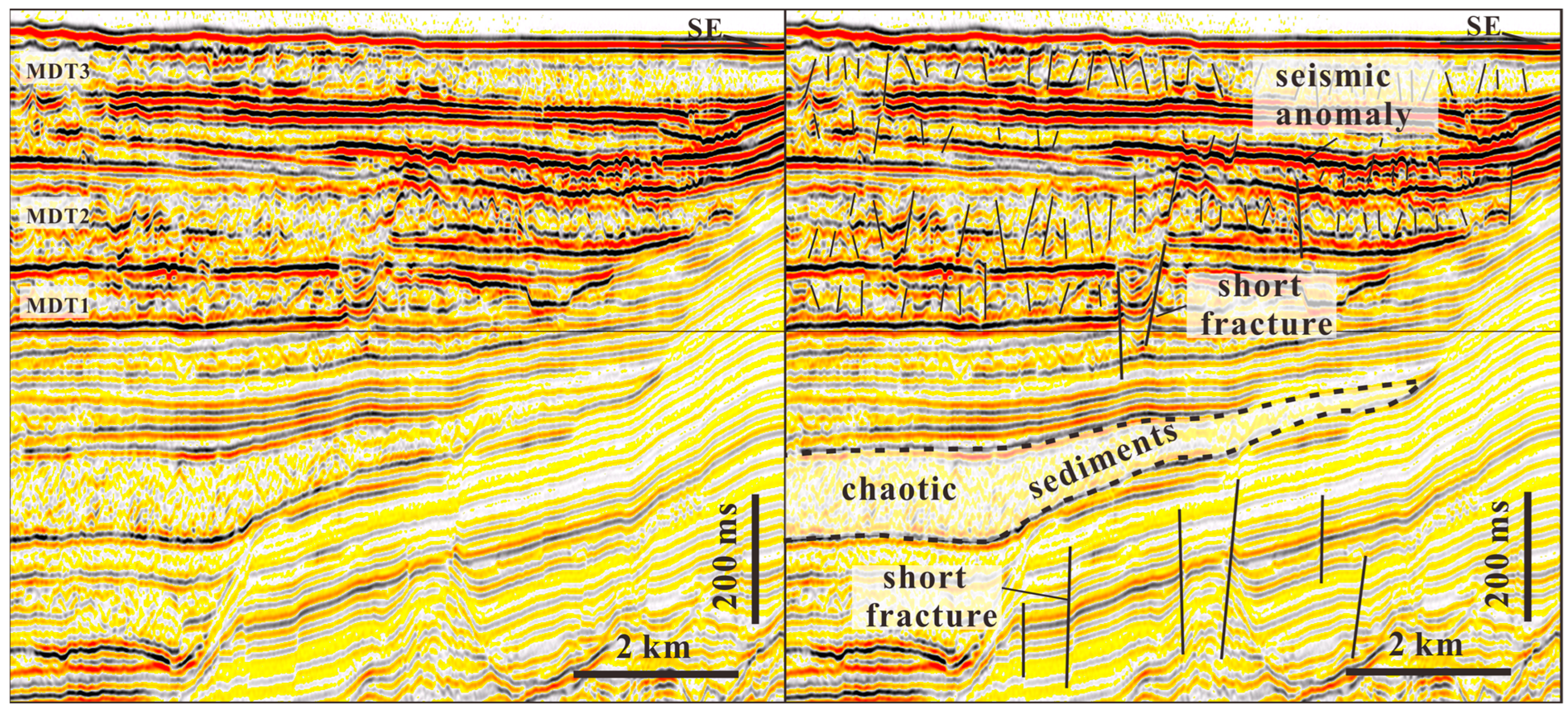
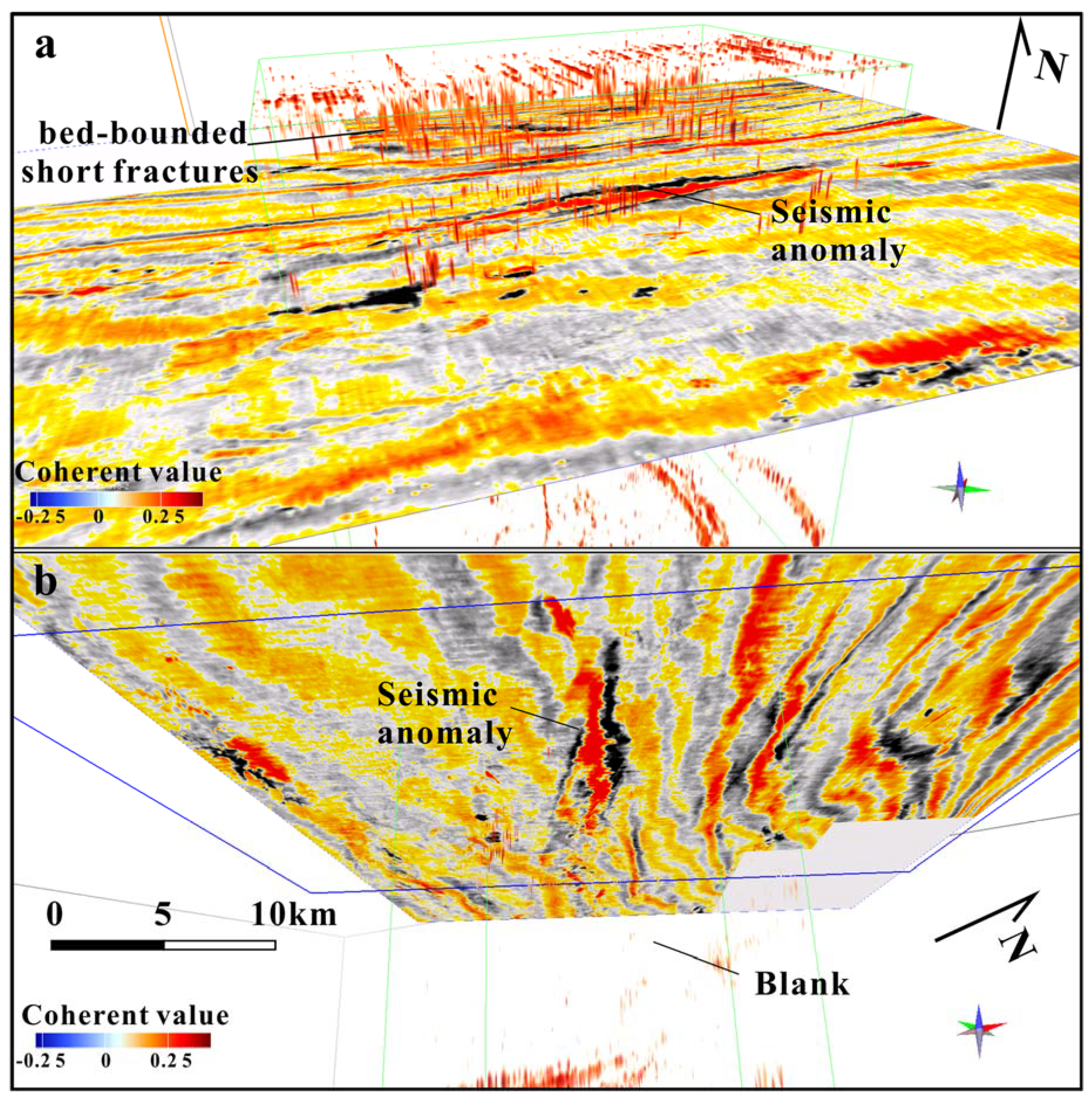
4.2.1. Bed-Bounded Fractures/Microfaults

Figure 3 shows that in the shallow layers, the seismic phases have the characteristics of a continuous strong amplitude reflection and chaotic reflection, which alternate with each other. The chaotic seismic reflection layers are considered mass transport depositions (MTDs) by Liang et al. [9], and are divided into three segments (Figure 2B and Figure 3). A magnified seismic profile is visible in these sediments, and many fractures are evident. Weak seismic reflection phases in deeper layers and local continuous seismic phases with medium-high amplitudes can also be observed. Small and few short fractures/microfaults (Figure 3) are discrete and disappear abruptly in some weak seismic reflection phases. Moreover, no seismic reflection characteristic resembles a small gas chimney near the fracture or in the strata.
Another type of bed-bounded fractures/microfaults are polygonal faults, which occur in the Miocene strata (Figure 4). Most of these short fractures develop in the Miocene Meishan and Sanya formations (T40–T60), with NW- and NE-dipping directions and angles of approximately 60–75°. These faults are interconnected via a few long fractures/faults in the Paleogene strata and fractures in the Pliocene strata (above T30), thus forming a complex fault–fracture system.

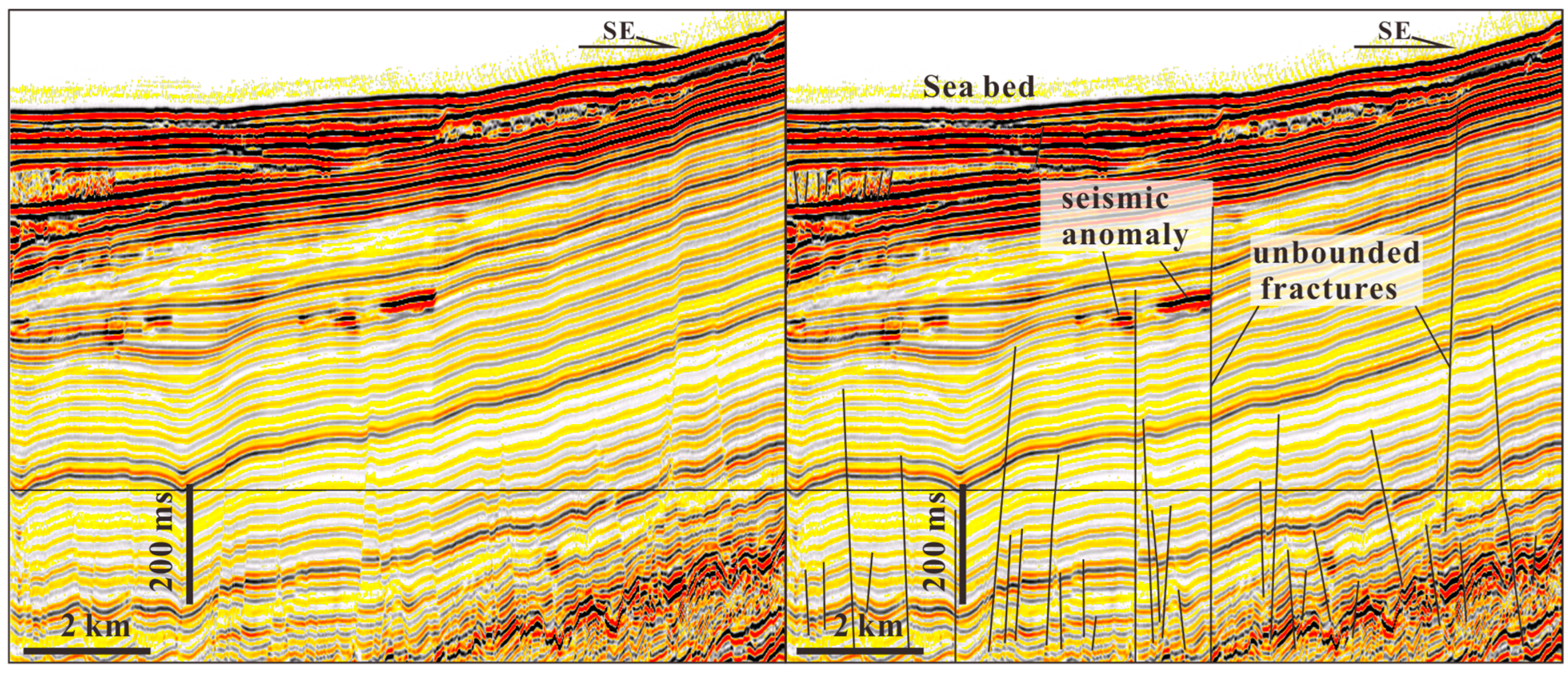
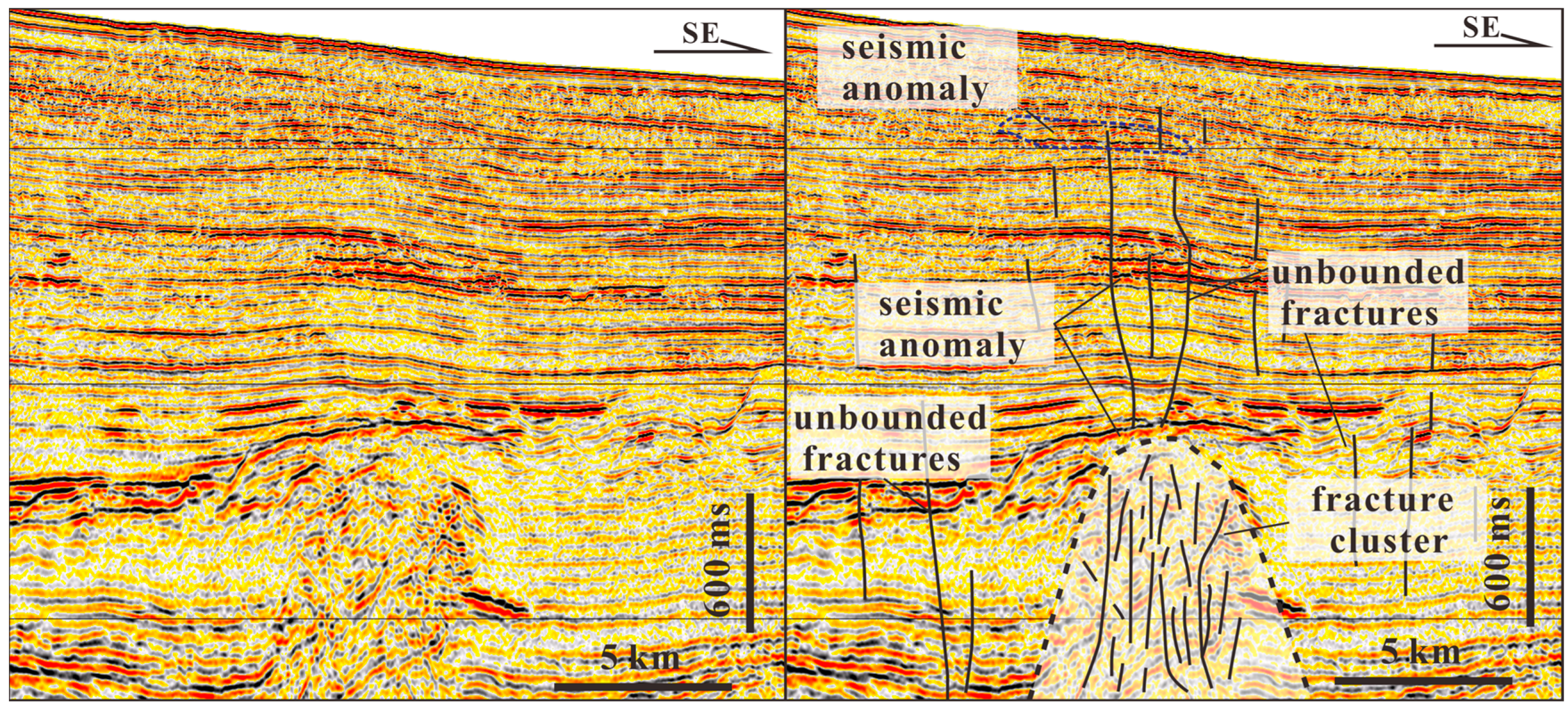
4.2.2. Unbounded Fractures/Faults

Figure 6 shows fractures/faults with a large vertical scale that can cut through the thick, weak, and continuous (partially discontinuous as faults) seismic phases of different formations upward and even extend to the seabed. These fractures also extend directly upward to the seismic anomaly. In the Yinggehai Basin, long fractures on the wings of diapir structures represent a common pattern, and gas fields are primarily formed in association with these fractures [27,50,51]. In Figure 5, a number of smaller fractures can be observed near unbounded fractures, which indicates that there are widespread fractures of different scales that develop continuously in a certain geological body (Figure 2 and Figure 7).

4.2.3. Fracture Bunch

A fragmented bunch that is packed with significant quantities of fluid is shown spatially in Figure 6a, where the seismic reflection characteristics are fuzzy zones and gas chimneys are formed in the vertical direction; meanwhile, Figure 6b shows a case in which there are only traces of a fracture. These occur in Miocene–Pliocene formations, where the range in the two-way reflection time of the seismic wave velocity is approximately 2.4–3.2 S. In the seismic section, fracture bunches with no chimney present neither chaotic reflections nor shaking phenomena in the strata, but show more discontinuous characteristics than the adjacent areas. Løseth et al. [24] defined this area as a vertical discontinuity zone, whereas Andresen [30] describes it as a pipe-like zone in which there are vertically elongated features [3] that are visible more than 1000 m below some craters; these are shown on time slices as a circularly deformed seismic zone. Deposit surface reflections often bend around the pipes in a narrow anticline.

4.2.4. Fracture Cluster

Finally, a large range of fractures with high fracture densities and different lengths are developed at the bottom of the leakage system (Figure 8); these fractures mainly occur in Oligocene–Early Miocene formations, and the range in the two-way reflection time of the seismic wave velocity is approximately 3.2–4.5 S. Because the primary seismic strata are almost destroyed and long and short fractures intensely develop, the characteristics of these fractures are consistent with those of a fracture cluster. As can be observed from the seismic image, compared with the seismic reflection characteristics of the surrounding rock, the strata inside the fracture cluster show a discontinuous and chaotic reflection. It is random scattering that occurs within the fracture cluster, and there is significant anisotropy at the reflection interface. For seismic sections in which the stratigraphic reflections have deteriorated, these features make the area either absent or weak, and it comes to resemble a vertical wipe-out zone [52]. The external geological body morphology and seismic reflection characteristics of the fracture cluster are similar to those of mud diapirs or basement fault blocks, featuring a cone shape but irregular contours.

4.3. Spatial Distribution of Fractures

Figure 8 shows the complex fracture structure, which forms an excellent fluid-charging relationship with the BSR area, as Yu et al. [27] discussed. The key characteristics are described in the following:
(1)
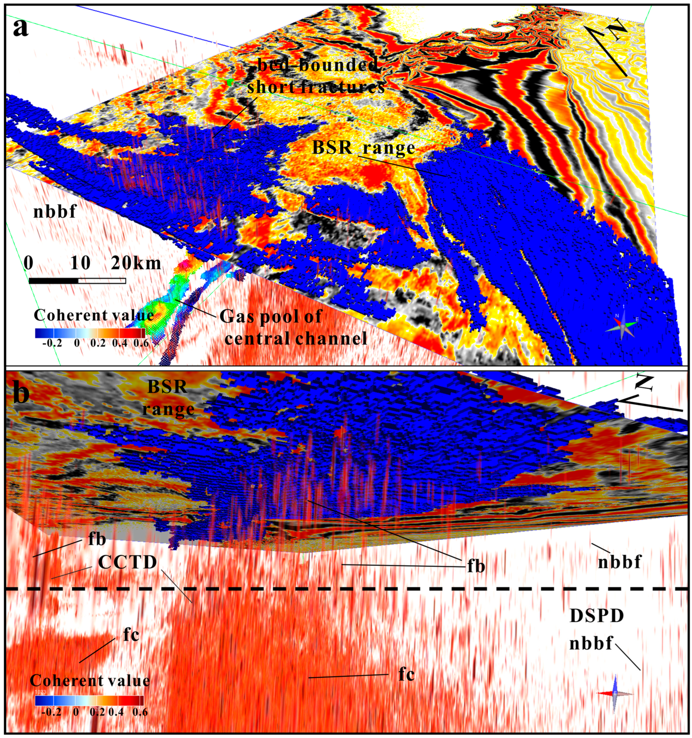
It can be observed that a large number of fractures are dispersed throughout the stratigraphic space of the research area, which differs from the observations of the seismic section. Figure 8a presents the distribution of spatial fractures above the horizontal slice, while Figure 8b presents the distribution of spatial fractures below the horizontal slice. The number of fractures is significantly higher below the horizontal slice, and the size of the fractures diminishes in the vertical direction. Laterally, the fractures within the delineated BSR area are much more developed than those far from the BSR. Therefore, the fracture system and BSR constitute a good coupling relationship.
(2)
Observations of the distribution structure of fractures below the BSR (or slice) show that the fractures are well dispersed (DSPD) but also exhibit local concentration (CCTD). Among the dispersed fractures, the number of fractures observed across the BSR/slice is exceedingly small; hence, the dispersed fractures appear independent or few and are challenging to observe in this interval. However, the dispersal form of the fractures is far more widespread than that above the BSR/slice (Figure 8b). As stated above, two fracture clusters are observed in this area, and most fractures have stub or cone-shaped fracture outlines. Furthermore, the dense fracture assemblage in the deeper formation space gradually decreases upward, eventually forming many bunched fracture assemblages that cut through the BSR/slice (Figure 8b).
(3)
The observations also show that the short fractures in the MDTs above the slice (seismic anomaly) are moderately developed (Figure 9a), with similar scales and a uniform distribution (Figure 9); in addition, fewer fractures are observed below the slice than above (Figure 9b).

5. Discussion

5.1. Possible Geneses of Different Kinds of Fractures

The distribution patterns of fractures, such as DSPD and CCTD features, are closely related to specific geological geneses. The fractures observed in Figure 3, Figure 4, Figure 5, Figure 6 and Figure 7 reveal the various genetic conditions that form these bed-bounded fractures, unbounded fractures, fracture bunches, and fracture clusters.
(1)
Bed-bounded fractures
There are two types of bed-bounded fractures here: polygonal fractures in the Meishan and Sanya formations, and high-density small fractures in the ultra-shallow MTDs.
Polygonal faults are present in neither ultra-shallow layers nor in the deep basin, but rather in certain layers beneath the seismic anomaly (Figure 4). Although many theories have been put forth in order to explain how polygonal faults form, including density inversion [53], syneresis [54,55,56], a low coefficient of friction [57] (Goulty and Swarbrick, 2005), gravity sliding [58], or a genetically shear failure [59], their formation in this area is largely related to the syneresis that results from gravitational spreading and the overpressure of hydrofracture [60]. In geneses, firstly, the main fault in deeper formations partially controls these polygonal faults, and the continuous activity of the main fault causes the differential subsidence of its down wall (Figure 4), which leads to the inhomogeneous compaction of the sedimentary layers. Li et al. [60] also found that, because sandstone is less fluid-confined than mudstone, their capacity for dehydration differs, which leads to a difference in the extent of polygon development. For example, the polygonal fault scale near the sandstone in this region is smaller than that in the mudstone, that is, the large-grained sandstone inhibits the formation of a polygonal fault because it has a superior effect regarding pressure relief.
In addition to polygonal faults, the causes of the formation of high-density fractures are relatively clear. Su et al. [61] found that the submarine landslide mechanism in the QDNB might produce such MTDs, and pointed out that the activity of unstable MTDs might result in shear fractures. However, except for high-density short fractures that are unevenly distributed close to the seabed, no notable faults or leakage channels were found in the three sets of MTDs (Figure 3). The numerous fractures were only visible when the seismic profile was enlarged (Figure 3) [9]. Løseth’s [24] sedimentary compaction drainage mechanism presents a plausible justification for the formation of large-scale fractures in MTDs. Due to the rapid and almost instantaneous occurrence of MTDs, they contain considerable volumes of seawater. As sedimentary layers are buried, the water in MTDs is rapidly discharged upward, resulting in the formation of many fractures due to hydraulic action. Moreover, we also observed an abundance of pockmarks on the seafloor, which indicate that water drains along these fractures.
(2)
Unbounded fractures
Unbounded fractures are the most common phenomenon in rifted basins and are mainly caused by strong tectonic movements, such as extensional tectonism and its associated fault displacement, stress concentration, and intense sustained overpressure [62].
Gillespie et al. [49] found that unbounded fractures are caused by the occurrence of fractures in an effectively homogeneous medium, in which fractures are positioned without regard to bed boundaries; this is because, in homogeneous media, the formation boundary cannot effectively constrain the development of fractures. This result also occurs in inhomogeneous media when the tectonic stress is greater than the binding effect that the formation interface has on fracture development. As described by [63] and influenced by the extensional tectonics of the normal faulting of the Late Pliocene–Early Pleistocene to present day, moderately fractured rocks present fractures that are confined to a single layer, while intensely fractured rocks present fractures that appear across layers.
However, the formation of unbounded fractures/faults in Figure 5 should have no correlation with major fault activity; however, due to the rapid differential subsidence that occurs during the post-rift stage and because there was little fault activity in the post-rift period, these fractures could not have existed as a result of major fault activity.
Some of the unbounded long fractures in Figure 7 were generated by the fluid penetrating the formation under continuous overpressure [27]. Overpressure fractures refer to the many fractures that are caused by the overpressure induced by the fluid front penetrating the overlying strata, and fluids occupying these fractures to form a dynamic equilibrium system in which fracture groups and sand bodies coexist [47]. Hao et al. [63] noted that, when the fluid pressure of the deep formation is greater than 85% of the water purification pressure in the overlying formation, a piercing effect will occur, resulting in the fracture of the overlaying formations.
(3)
Fracture bunches
Generally, fracture bunches are smaller in scale (fracture density or abundance) than fracture clusters and tend to develop in the mud diapir wing, within the gas chimney (Figure 7), and at the top of the diapir in the overpressure–normal transition zone. The development of this fracture on the diapir wings is primarily a result of the structural deformation of the surrounding rock strata, which is caused by diapir tectonic activity that results in local fluid having piercing effects; this is therefore associated with the diapir structure joint. Overpressure–normal transition zones are typically found near diapirs (or gas chimneys), while formation penetration occurs in the pressure transition zone of the strata beneath.
(4)
Fracture clusters
The fracture scale in the deeper formation gradually decreases upward, thus indicating either stronger tectonic activity during the rifting stage than during the post-rifting stage, or greater deformation in the deep stratum due to overpressure or fluid piercing during the post-rifting event. The local CCTD distribution of fractures may be related to the overpressure sac, stress concentration zones, and basement fault blocks. The QDNB developed overpressure, which was caused by the generation of hydrocarbons and hydrothermal processes [62]; in addition, the pressure coefficient of the hydrocarbon-generating center can be up to 2.3 (Figure 10). When pressure is transmitted to the sand-bearing sediments nearby, due to the sealing effect of the surrounding rock, an overpressure sac is formed. When the fluid pressure in the overpressure sac is greater than the bonding force of the particles in the sand-bearing sediments, the sediments will be destroyed and a fracture cluster with an outline similar to that of the sand-bearing sediments will be formed (Figure 7 and Figure 8). In addition, the magma activity of the Triassic period formed a large area of granite basement (228.9 ± 1 Ma) [64]. During the Eocene period, the basin began to rift and a large number of basement fault blocks were produced. The tertiary overlying layer on the Indosinian granite basement block produced many fractures under the action of the transverse bending and folding [65].

5.2. Relationship between the BSR and Fracture System and Its Implications for Fluid Transport

The pattern of fracture development can be used to evaluate the capacity for heterogeneous fluid flow [66], as fractures control the fluid transport pathway and accumulation efficiency. High-density and long fractures are likely to cause gas transport, whereas low-density and short fractures are not.
Hydrates arise in thin sands and fractures due to the migration of diffusive methane or the short migration of microbially produced methane from marine mud units, as Hillman et al. [67] discussed. Here, microbial methane accumulation is emphasized, where both fractures and thin sand beds are developed in thick source units. This case provides a reasonable model for investigating how natural gas accumulates and migrates from deep gas sources to shallow reservoirs.
In this region, fractures have been confirmed to act as the upper leakage system and reservoir of the gas hydrate above the gas chimney [9], indicating that long-distance migration and accumulation largely depend on fractures. Therefore, a new model in which deep gas is transported to shallow reservoirs through fracture systems is worth exploring.
As shown by the above-described examples (Figure 3, Figure 4, Figure 5, Figure 6, Figure 7, Figure 8 and Figure 9), a single short fracture cannot provide the transport system necessary for the formation of a hydrate reservoir. Natural fractures often exist in other transportation systems, such as sand bodies and faults [68,69]. Hence, in the study area, the relationship between the BSR and fracture system and the implications for gas leakage are proposed in six models (Figure 11):
(1) There are only several discrete long fractures below the BSR that extend deep into the gas source, while many fractures above the BSR cut through thin sediments to the seabed and form a complete seepage system (Figure 3 and Figure 11a). Pockmarks are considered to be developed on the seabed of the seepage system [9]. Despite not being observed, this phenomenon is very likely to exist in the deep-water region due to the collapse of the continental slope and the impact of loose sediments on drainage. Therefore, it is equally important to study the charging of shallow reservoirs and the accumulation of fluids in the deep-water area.
During the opening of fractures, gas fluids can migrate from the gas source to the shallow reservoir via the long fracture system. However, because of the large number of fractures above the reservoir that connect directly with the seabed, and considering that the gas charge exceeds the quantity of gas escaping from the hydrate reservoir, gas cannot accumulate in the reservoir and reach the saturation necessary for the formation of the hydrate crystal cage. Thus, hydrates cannot be formed [70,71].
(2) In this condition, unbounded and discrete short fractures develop below the BSR; however, some thin sand layers also exist (Figure 11b). This phenomenon usually occurs in sedimentary areas with weak tectonic and fluid activity. The fractures appear discrete and disappear abruptly in some weak seismic reflection phases, which may be interpreted to have mainly developed in some thick mudstones. In contrast, the fractures that disappear in medium-high amplitude seismic phases may be considered to cut through the thin sand layer in some intervals and even intersect with the BSR. Overall, the number and vertical scales of the fractures are small, thus leading to short extension distances, and the fractures cannot connect.
Therefore, the appearance of discrete short fractures indicates that the gas source, fractures, deep and thin sand body, and BSR at the shallow layer cannot constitute a complete transport and seepage system. Gas from the deep strata cannot be transported through these short fractures and accumulate in the reservoir in which the BSR is located; the occurrence of a seismic anomaly may be the response to a sand body.
(3) In some cases, unbounded long fractures develop below the BSR. In Figure 11c, unbounded fractures have developed at a low density with a dispersed pattern; these are able to cut through more than 5–6 seismic phases vertically, reaching hundreds or even thousands of meters. Therefore, some long fractures are developed only in thick mudstone segment intervals, while others cut through the extremely thick mudstone layer to connect the gas source with the BSR (Figure 11c). However, there is no evidence in the data that these faults reach the bottom or that they are connected to the current seafloor pockmarks.
Unbounded long fractures commonly appear near secondary faults in rifted basins [72], strike-slip zones in strike-slip basins, late-deposited strata around strike-slip faults [73], and in the wings of diapir structures [50,74]. Due to their inability to form focused fluid migration pathways such as fracture tubes, discrete long fractures should not be suitable for the migration and accumulation of gas. To date, fractures of this form have been associated with few hydrates. This may be because there is not sufficient gas and pore space available for the formation of gas hydrates [75], which could explain why the well (well 7) reported by Deng [66] above the gas chimneys in this area did not encounter significant hydrates.
(4) In the fourth case, as shown in Figure 11d, unbounded long fractures, bed-bounded fractures, and thin sand layers develop below the BSR.
The polygonal fault systems are formed by long and short fractures developed in the Sanya and Meishan formations, which contain thin sand layers. Under the influence of fault activities, some polygonal faults are further developed, and some faults extend upward to the Meishan, Huangliu, and Yinggehai formations (Figure 4).
The seepage system mainly controls the migration and accumulation of fluids from the Yacheng formation to the shallow strata. The reactivation of major faults and the subsequent migration of fluid along fault planes may determine the fluid flow characteristics [76,77]. Gas produced by the Yacheng formation first migrated to the shallow layer through the main fault and then diffused laterally between the small faults and sand bodies of the Sanya formation and Meishan formation. Polygonal fault systems are considered high-permeability systems and major fluid sources, and are capable of expelling up to sixty percent of their capacity in water [78,79]. Because the highly permeable strata include brittle fractures with tectonic action [80], polygonal faults, and thin sand layers, the strata are fragmented [81,82], and the fractured layer at the top, together with shallow fractures, forms a unified and efficient leakage system for the migration of gas. Finally, the gas continues to migrate along the shallow longer fractures to the trap, forming a deposit of gas hydrates.
(5) Figure 11e presents the relationships among the fracture bunches, the BSR, and the migration and accumulation of fluid. In contrast to discrete faults and fractures, fracture bunches show the concentrated development of multiple fractures. As they commonly contain much fluid, seismic reflections exhibit fuzzy zones or gas chimneys in the vertical direction. The discontinuous and fuzzy seismic reflection characteristics within a fractured bunch reveal that the concentrated generation of fractures breaks the strata between them (Figure 6), thus forming a spatial network structure within the bunch; this is similar to the concept of fracture pipes proposed by Løseth et al. [22]. Thus, the transport system is developed in diapirs, gas chimneys, or local shear fracture zones. In the shallower strata, such fracture aggregates often connect downward to diapirs and gas chimneys, thus extending upward to the BSR in the ultra-shallow layers.
Fracture bunches can be considered an effective fluid transport system, and compared with those of discrete fractures, the scale of fracture bunches is larger, and their fluid permeability is higher. The root of the fracture bunch usually starts at the overpressure source (such as the gas source rock), and the spatial network structure of the fracture bunch provides an essential path for the migration of gas to the shallow GHSZ and its accumulation there.
(6) In the last situation, as shown in Figure 11f, a wide range of fractures are present below the BSR; these fractures possess a high fracture density and different lengths, thus forming a transport system with a small number of fractures above it. In most cases, the fracture cluster develops in a structure such as a gas chimney or mud diapir, so the characteristics of the fuzzy zone, blank reflection zone, and chaotic reflection are often presented in the seismic section. The existence of fracture clusters is often a sign of the development of a transport system, in which nearby long and short fractures often accompany these clusters. Therefore, seismic anomalous bodies or BSRs are commonly identified in the shallow layer.
According to the six models of fluid transport to the hydrate reservoir along fractures, fluid accumulation in the reservoir mainly occurs via models d, e, and f, while models a, b, and c are not conducive to fluid accumulation in the reservoir.
The spatial distribution and structure of short fractures, long fractures, fracture bunches, and fracture clusters can determine whether fluids are transported to and accumulated in hydrate reservoirs. However, the leakage system of pyrolysis gas is controlled by faults, diapirs, and other deep structures. For example, the charging period of overpressure-related fractures is subjected to the generation and development of overpressure [83], and the formation of structural fractures is controlled by tectonic activities [4,84]; meanwhile, polygonal fractures are related to the mechanism implicated in the formation of local fractures [81]. Therefore, spatial configuration models of fractures and traditional transport systems, such as diapirs, fractures, sand bodies, and hydrate reservoirs, are significant in the evaluation of seepage systems.

6. Conclusions

Investigating the spatial distribution and characteristics of fractures/microfaults provides a broader view of the thermogenic migration and accumulation of gas in leakage systems in deep-water basins and enables a more systematic analysis of fluid migration pathways to be conducted. The following conclusions may be derived:
(1)
Compared with observing the field outcrop and core drilling, observing seismic images and the hollowed out coherent volume is more convenient when aiming to analyze the detailed fracture distribution structure in deep-water basins.
(2)
Based on the distribution patterns in the seismic images of fractures and the intersectional relationships between fractures and strata, four types of fractures were identified: bed-bounded fractures/microfaults, unbounded fractures, fracture bunches, and fracture clusters. These types of fractures represent the most important existing forms of fractures in sedimentary basins.
(3)
Bed-bounded fractures/microfaults are mainly short, have high density, and develop in MTDs of ultra-shallow layer or Meishan and Sanya formations. Unbounded fractures/microfaults are mainly long, discrete, and occur in Miocene–Pliocene formations; they also connect hydrocarbon source rock with reservoirs. Fracture bunches and fracture clusters commonly develop with the accumulation of large numbers of fractures, and occur in Oligocene–Early Miocene formations.
(4)
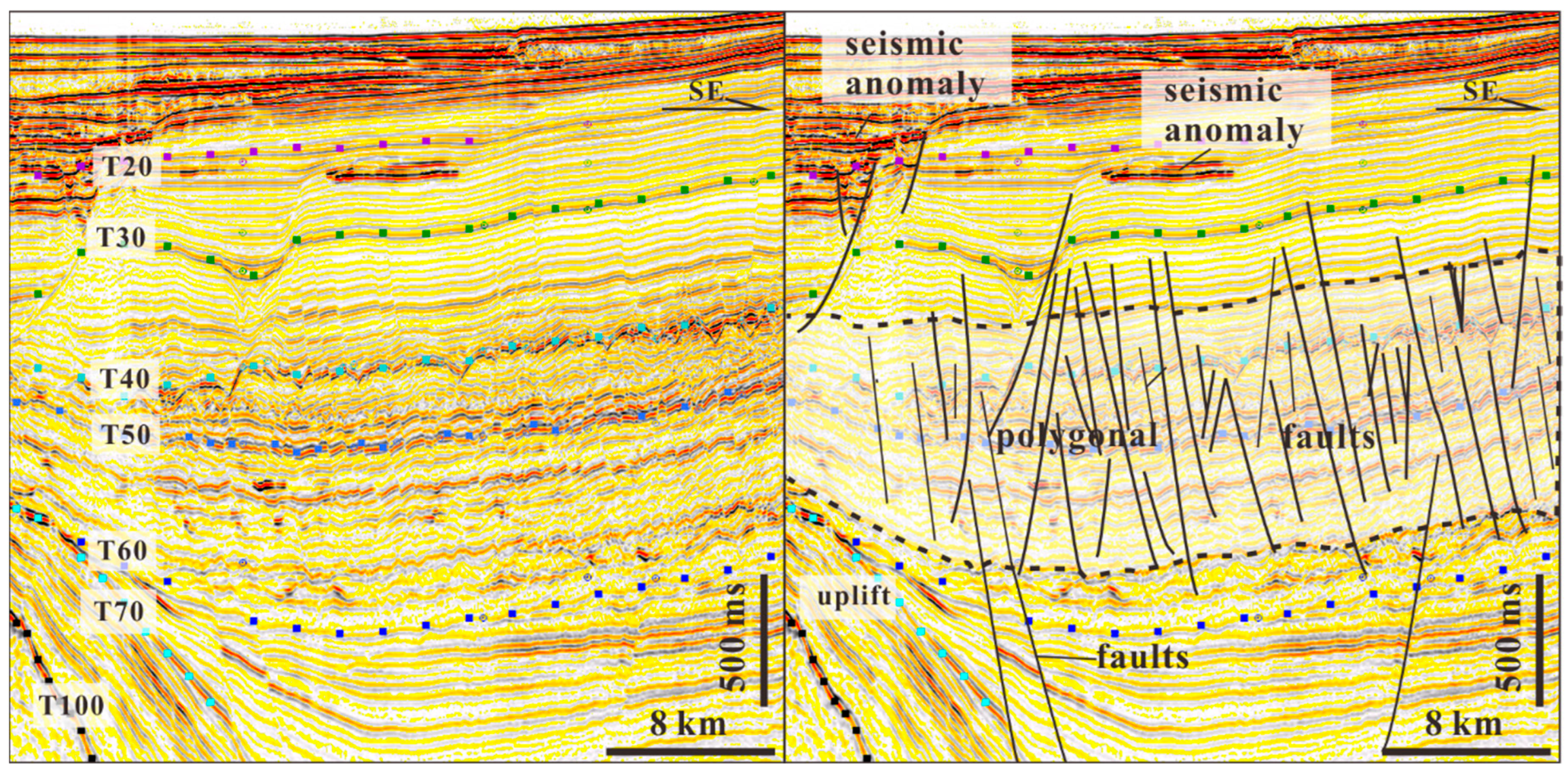
The differences in scale (length, density, etc.), development intervals, and combination form of the various types of fractures are closely related to their respective geological origin. Bed-bounded fractures/microfaults and polygonal faults are formed via drainage mechanisms and dehydration shrinkage in the MTDs. Unbounded fractures are mainly caused by strong tectonic movements, differential subsidence, and sustained overpressure. The release of gas chimney pressure in the diapir top overpressure–normal transition zone tends to form fracture bunches. These fracture clusters may be related to diapirs and transverse bending and folding over basement fault blocks.
(5)
In the 3D space view, the fractures above the anomaly are substantially less numerous than those below it. This pattern generates an acceptable supply of fluid/gas with limited dispersion during the hydrate accumulation process, making this pattern a generally suitable indicator of hydrate deposits and valuable when checking for fluid/gas leakage.
(6)
The pattern of fracture development can be used to evaluate the capacity for heterogeneous fluid flow. According to the spatial distribution and seismic reflection characteristics of fractures, there are at least six main routes for the transmission and accumulation of fluid/gas; these involve assemblages of fractures, thin sand layers, and hydrate reservoirs. They can effectively connect hydrocarbon sources to hydrate reservoirs in shallow layers, thus rendering them beneficial to the accumulation of fluid/gas. This model can explain the migration and accumulation characteristics of deeply sourced pyrolysis gas, as well as the vertical charging mode of medium and shallow biogenic gas reservoirs.

Author Contributions

Conceptualization, J.Y.; Formal analysis, R.S.; Investigation, R.S. and C.C.; Data curation, C.C.; Writing—original draft, J.Y.; Visualization, R.S.; Funding acquisition, J.Y. All authors have read and agreed to the published version of the manuscript.

Funding

This research was funded by the National Key Technology Research and Development Program of China during the “13th Five-Year Plan” grant number No. 2016ZX05024-002.

Data Availability Statement

The data that have been used are confidential.

Acknowledgments

We would like to thank Hainan Company, CNOOC Limited, for their permission to use the 3D seismic volume. We are also very grateful to the reviewers and editors for their thoughtful and useful comments and criticisms, which helped to improve the manuscript.

Conflicts of Interest

Authors Junfeng Yu and Caixia Chao were employed by the company Zhanjiang Company, CNOOC Limited. Author Ruiyou Song was employed by the company Hainan Company, CNOOC Limited.

References

  1. Guliev, I.S. A Review of Mud Volcanism; Azerbaijan Academy of Sciences Institute of Geology: Baku, Azerbaijan, 1992; p. 65. [Google Scholar]
  2. Graue, K. Mud volcanoes in deep-water Nigeria. Mar. Pet. Geol. 2000, 17, 959–974. [Google Scholar] [CrossRef]
  3. Baristeas, C.; Anka, Z.; Primio, R.; Rodriguez, J.F.; Marchal, D.; Dominguez, F. Distribution of hydrocarbon leakage indicators in the Malvinas Basin, offshore Argentine continental margin. Mar. Geol. 2012, 332–334, 56–74. [Google Scholar] [CrossRef]
  4. Brown, A. Evaluation of possible gas microseepage mechanisms. AAPG Bull. 2000, 84, 1775–1789. [Google Scholar]
  5. Riedel, M.; Collett, T.S.; Kumar, P.; Sathe, A.V.; Cook, A. Seismic imaging of a fractured gas hydrate system in the Krishna–Godavari Basin offshore India. Mar. Pet. Geol. 2010, 27, 1476–1493. [Google Scholar] [CrossRef]
  6. Yoo, D.G.; Kang, N.K.; Bo, Y.Y.; Kim, G.Y.; Ryu, B.J.; Lee, K.; Riedel, M. Occurrence and seismic characteristics of gas hydrate in the Ulleung Basin, East Sea. Mar. Pet. Geol. 2013, 47, 236–247. [Google Scholar] [CrossRef]
  7. Zhang, Z.; Wright, C.S. Quantitative interpretations and assessments of a fractured gas hydrate reservoir using three-dimensional seismic and LWD data in Kutei basin, East Kalimantan, offshore Indonesia. Mar. Pet. Geol. 2017, 84, 257–273. [Google Scholar] [CrossRef]
  8. Cook, A.E.; Goldberg, D.; Kleinberg, R. Fracture-controlled gas hydrate systems in the northern Gulf of Mexico. Mar. Pet. Geol. 2008, 25, 932–941. [Google Scholar] [CrossRef]
  9. Liang, J.Q.; Zhang, W.; Lu, J.A.; Wei, J.G.; Kuang, Z.G.; He, Y.L.; GMGS5 Expedition. Geological occurrence and accumulation mechanism of natural gas hydrates in the eastern Qiongdongnan Basin of the South China Sea: Insights from site GMGS5-W9-2018. Mar. Geol. 2019, 418, 106402. [Google Scholar] [CrossRef]
  10. Bai, Y.; Yang, J.; Sun, J.; Shang, X.; Han, J. Self-filling and plugging performance of a thixotropic polymer gel for lost circulation control in fractured formation. Geoenergy Sci. Eng. 2023, 225, 211717. [Google Scholar] [CrossRef]
  11. Martel, S.J.; Pollard, D.D. Mechanics of slip and fracture along small faults and simple strike-slip fault zones in granitic rock. J. Geophys. Res. 1989, 94, 9417–9428. [Google Scholar] [CrossRef]
  12. Feng, S.; Wang, H.; Cui, Y.; Ye, Y.; Liu, Y.; Li, X.; Wang, H.; Yang, R. Fractal discrete fracture network model for the analysis of radon migration in fractured media. Comput. Geotec. 2020, 128, 103810. [Google Scholar] [CrossRef]
  13. Hooker, J.N.; Laubach, S.E.; Marrett, R. Fracture-aperture sizedfrequency, spatial distribution, and growth processes in strata-bounded and non-strata-bounded fractures, Cambrian Mesón Group, NW Argentina. J. Struct. Geol. 2013, 54, 54–71. [Google Scholar] [CrossRef]
  14. Narr, W. Fracture density in the deep subsurface: Techniques with application to point arguello oil field. AAPG Bull. 1991, 75, 1300–1323. [Google Scholar]
  15. Zeng, L.; Liu, H. Influence of fractures on the development of low-permeability sandstone reservoirs: A case study from the Taizhao district, Daqing Oilfield, China. J. Pet. Sci. Eng. 2010, 72, 120–127. [Google Scholar] [CrossRef]
  16. Fletcher, D.; Goss, E. Forecasting with neural networks: An application using bankruptcy data. Inf. Manag. 1993, 24, 159–167. [Google Scholar] [CrossRef]
  17. Ligtenberg, H.; Connolly, D. Chimney detection and interpretation, revealing sealing quality of faults, geohazards, charge of and leakage from reservoirs. J. Geochem. Explor. 2003, 78–79, 385–387. [Google Scholar] [CrossRef]
  18. Sibson, R. A Brief Description of Natural Neighbor Interpolation. In Interpolating Multivariate Data; John Wiley & Sons: New York, NY, USA, 1981; pp. 21–36. [Google Scholar]
  19. Bour, O.; Davy, P.; Darcel, C.; Odling, N.E. A statistical scaling model for fracture network geometry, with validation on a multiscale mapping of a joint network (Hornelen Basin, Norway). J. Geophys. Res. 2002, 107, 2113. [Google Scholar] [CrossRef]
  20. Molron, J.; Linde, N.; Baron, L.; Selroos, J.O.; Darcel, C.; Davy, P. Which fractures are imaged with Ground Penetrating Radar? Results from an experiment in the Äspö Hardrock Laboratory, Sweden. Eng. Geol. 2020, 273, 105674. [Google Scholar] [CrossRef]
  21. Løseth, H.; Wensaas, L.; Arntsen, B.; Hanken, N.; Basire, C.; Graue, K. 1000m Long Gas Blow-Out Pipes; Extended Abstract; EAGE: Amsterdam, The Netherlands, 2001. [Google Scholar]
  22. Løseth, H.; Wensaas, L.; Arntsen, B. Gas chimneys-indication of fractured caprocks. In Proceedings of the AAPG Hedberg Conference, Near Surface Hydrocarbon Migration, Mechanisms and Seepage Rates, Vancouver, BC, Canada, 7–10 April 2002. Extended Abstract. [Google Scholar]
  23. Løseth, H.; Gading, M.; Wensaas, L. Hydrocarbon leakage interpreted on seismic data. Mar. Pet. Geol. 2009, 26, 1304–1319. [Google Scholar] [CrossRef]
  24. Navalpakam, R.S.; Pecher, I.A.; Stern, T. Weak and segmented bottom simulating reflections on the Hikurangi margin, New Zealand—Implications for gas hydrate reservoir rocks. J. Pet. Sci. Eng. 2012, 88–89, 29–40. [Google Scholar] [CrossRef]
  25. Rubin, A.M.; Allan, M. Tensile fracture of rock at high confining pressure: Implications for dike propagation. J. Geophys. Res. 1993, 98, 15919–15935. [Google Scholar] [CrossRef]
  26. Yu, J.F.; Song, R.Y.; Chao, C.X.; Pan, G.C. Spatial distribution characteristics of fracture system in BSR zone in deep water area of the Qiongdongnan Basin. Haiyang Xuebao 2020, 429, 69–78. [Google Scholar]
  27. Osborne, M.J.; Swarbrick, R.E. Mechanisms for generating overpressure in sedimentary basins: A reevaluation. Am. Assoc. Pet. Geol. Bull. 1997, 81, 1023–1041. [Google Scholar]
  28. Huuse, M.; Jackson, C.A.-L.; Van Rensbergen, P.; Davies, R.J.; Flemings, P.B.; Dixon, R.J. Subsurface sediment remobilization and fluid flow in sedimentary basins: An overview. Basin Res. 2010, 22, 342–360. [Google Scholar] [CrossRef]
  29. Andresen, K.J.; Huuse, M.; Schødt, N.H.; Clausen, L.F.; Seidler, L. Hydrocarbon plumbing systems of salt mini basins offshore Angola revealed by three-dimensional seismic analysis. Am. Assoc. Pet. Geol. Bull. 2011, 95, 1039–1065. [Google Scholar]
  30. Petrov, Y. Structural-temporal approach to modeling of fracture dynamics in brittle media. In Rock Dynamics and Applications—State of the Art; CRC Press: Boca Raton, FL, USA, 2013; pp. 101–110. [Google Scholar]
  31. Howard, J.H. Description of natural fracture systems for quantitative use in petroleum geology. AAPG Bull. 1990, 74, 151–162. [Google Scholar]
  32. Xu, H.Z.; Cai, D.S.; Sun, Z.P.; Huang, A.M.; Li, C.L.; He, L. Filling characters of the central submarine canyon of QiongdongnanBasin and its significance of petroleum geology. Acta Geol. Sin. 2012, 864, 641–650. [Google Scholar]
  33. Zhao, Z.X.; Sun, Z.; Wang, Z.F.; Sun, Z.P.; Liu, J.B.; Zhang, C.M. The high resolution sedimentary filling in Qiongdongnan Basin, Northern South China Sea. Mar. Geol. 2015, 361, 11–24. [Google Scholar] [CrossRef]
  34. Xie, H.; Qiu, N.; Shi, H.C.; Sun, Z.; Zeng, J.Y. Diachronous basin evolution along northern South China Sea: Result of a migrating Hainan plume? Tectonophysics 2022, 846, 229683. [Google Scholar] [CrossRef]
  35. Huang, B.J.; Xiao, X.M.; Li, X.X. Geochemistry and origins of natural gases in the Yinggehaiand Qiongdongnan Basins, offshore South China Sea. Org. Geochem. 2003, 34, 1009–1025. [Google Scholar] [CrossRef]
  36. Wang, Y.M.; Xu, Q.; Li, D.; Han, J.H.; Lü, M.; Wang, Y.F.; Li, W.G.; Wang, H.R. Late Miocene Red River submarine fan, northwestern South China Sea. Chin. Sci. Bull. 2011, 567, 781–787. [Google Scholar] [CrossRef]
  37. Wang, G.F.; Wu, C.L.; Zhou, J.Y.; Li, S.H. Sequence and stratigraphic analysis of the Tertiary in the Qiongdongnan Basin. Exp. Pet. Geol. 1998, 202, 124–127. [Google Scholar]
  38. Huang, B.J.; Li, X.S.; Wang, Z.F.; Li, L.; Huang, Y.W. Source forck geochemistry and gas potential in the deep water area, Qiongdongnan Basin. China Offshore Oil Gas 2012, 244, 1–7. [Google Scholar]
  39. Luo, J.H.; Zhu, P.M. Gravity induced deposits in the continental slope of Qiongdongnan Basin Based on Ultrahigh resolution AVU data. Geol. Sci. Technol. Inf. 2019, 38, 42–50. [Google Scholar]
  40. Li, C.Q.; Chen, H.H.; Zhang, S.L. Pressure field and its evolutional characteristics in Qiongdongnan Basin. Xinjiang Pet. Geol. 2002, 32, 389–392. [Google Scholar]
  41. Yao, Z.; Wang, Z.F.; Zuo, Q.M.; Dang, Y.Y.; Mao, X.L.; Man, X.; Li, W. Critical factors for the formation of large-scale deep-water gas field in central canyon system of Southeast Hainan Basin and its Exploration potential. Acta Pet. Sin. 2015, 3611, 1358–1365. [Google Scholar]
  42. Fan, C. Tectonic deformation features and petroleum geological significance in Yinggehai large strike-slip basin, South China Sea. Pet. Explor. Dev. 2018, 45, 204–214. [Google Scholar] [CrossRef]
  43. Jin, Y.; Fan, C.; Fu, X. Risk analysis of natural hydraulic fracturing in an overpressured basin with mud diapirs: A case study from the Yinggehai Basin, South China sea. J. Pet. Sci. Eng. 2021, 196, 107621. [Google Scholar] [CrossRef]
  44. Zhang, Z.; He, G.W.; Yao, H.Q.; Deng, X.G.; Yu, M.; Huang, W.; Deng, W.; Haider, S.W.; Sohoo, N.; Kalhoro, N.A. Diapir structure and its constraint on gas hydrate accumulation in the Makran accretionary prism, offshore Pakistan. China Geol. 2020, 34, 611–622. [Google Scholar] [CrossRef]
  45. Wei, J.G.; Wu, T.T.; Zhu, L.Q. Mixed gas sources induced co-existence of sI and sII gas hydrates in the Qiongdongnan Basin, South China Sea. Mar. Pet. Geol. 2021, 128, 105024. [Google Scholar] [CrossRef]
  46. Singh, D.; Kumar, P.C.; Sain, K. Interpretation of gas chimney from seismic data using artificial neural network: A study from Maari 3D prospect in the Taranaki basin, New Zealand. J. Nat. Gas Sci. Eng. 2016, 36, 339–357. [Google Scholar] [CrossRef]
  47. Song, R.Y.; Yu, J.F.; Chao, C.X.; Song, P.; Pan, G.C. Fracture identification technique and its application in gas and hydrate exploration. J. Ptopical Oceanogr. 2020, 391, 120–129. [Google Scholar]
  48. Petit, J.P.; Massonnat, G.; Pueo, F.; Rawnsley, K. Rapport de forme des fractures de Mode 1 dans les roches stratifées: Une étude de cas dans le basin Permien de Lodève. Bull. Cent. Rech. Explor. Prod. Elf Aquitaine 1994, 18, 211–229. [Google Scholar]
  49. Gillespie, P.A.; Walsh, J.J.; Watterson, J.; Bonson, C.G.; Manzocchi, T. Scaling relationships of joint and vein arrays from the Burren, Co. Clare, Ireland. J. Struct. Geol. 2001, 23, 183–201. [Google Scholar] [CrossRef]
  50. Yu, J.F.; Pei, J.X.; Wang, L.F.; Zhu, J.C.; Zhang, H.L. Gas pool properties and its exploration implications of the Dongfang13-2 gravity reservoir-overpressure gas field in Yinggehai Basin. Acta Pet. Sin. 2014, 355, 829–838. [Google Scholar]
  51. Huang, H.; Huang, B.; Huang, Y.; Xing, L.; Hui, T. Condensate origin and hydrocarbon accumulation mechanism of the deep-water giant gas field in western South China Sea: A case study of Lingshui 17-2 gas field in Qiongdongnan Basin. Pet. Explor. Dev. 2017, 44, 409–417. [Google Scholar] [CrossRef]
  52. Koch, S.; Schroeder, H.; Haeckel, M.; Berndt, C.; Bialas, J.; Papenberg, C.; Klaeschen, D.; Plaza-Faverola, A. Gas migration through Opouawe Bank at the Hikurangi margin offshore New Zealand. Geo-Mar. Lett. 2016, 36, 187–196. [Google Scholar] [CrossRef]
  53. Tewksbury, B.J.; Hogan, J.P.; Kattenhorn, S.A.; Mehrtens, C.J.; Tarabees, E.A. Polygonal faults in chalk: Insights from extensive exposures of the Khoman Formation, Western Desert, Egypt. Geology 2014, 42, 479–482. [Google Scholar] [CrossRef]
  54. Cartwright, J.A. Episodi c basin-wide hydrofracturing of overpressured Early Cenozoi c mudrock sequences in the North Sea Basin. Mar. Pet. Geol. 1994, 11, 587–607. [Google Scholar] [CrossRef]
  55. Berndt, C.; Bünz, S.; Clayton, T.; Mienert, J.; Saunders, M. Seismic character of bottom simulating reflectors: Examples from the mid-Norwegian margin. Mar. Pet. Geol. 2004, 21, 723–733. [Google Scholar] [CrossRef]
  56. Han, J.; Leng, J.; Wang, Y. Characteristics and genesis of the polygonal fault system in southern slope of the Qiongdongnan Basin, South China Sea. Mar. Pet. Geol. 2016, 70, 163–174. [Google Scholar] [CrossRef]
  57. Goulty, N.R.; Swarbrick, R.E. Development of polygonal fault systems: A test of hypotheses. J. Geol. Soc. 2005, 162, 587–590. [Google Scholar] [CrossRef]
  58. Clausen, J.A.; Gabrielsen, R.H.; Reksnes, P.A.; Nysaether, E. Development of intraformational (Oligocene–Miocene) faults in the northern North Sea: Influence of remote stresses and doming of Fennoscandia. J. Struct. Geol. 1999, 21, 1457–1475. [Google Scholar] [CrossRef]
  59. Li, J.; Mitra, S.; Qi, J. Seismic analysis of polygonal fault systems in the Great South Basin, New Zealand. Mar. Pet. Geol. 2020, 111, 638–649. [Google Scholar] [CrossRef]
  60. Li, Y.; Pu, R.; Zhao, X.; Zhang, G.; Fan, X.; Bao, J.; Wang, J. Differences of polygonal faults related to upper Miocene channels: A case study from the Beijiao sag of Qiongdongnan basin, South China Sea. J. Oceanol. Limnol. 2023, 411, 84–99. [Google Scholar] [CrossRef]
  61. Su, M.; Sha, Z.B.; Zhang, C.M.; Wang, H.B.; Wu, N.Y.; Yang, R.; Liang, J.Q.; Qiao, S.H.; Cong, X.R.; Liu, J. Types, Characteristics and Significances of Migrating Pathways of Gas-bearing Fluids in the Shenhu Area, Northern Continental Slope of the South China Sea. Acta Geol. Sin. Engl. Ed. 2017, 991, 219–231. [Google Scholar] [CrossRef]
  62. Hao, F.; Li, S.T. Developing mechanism and phase filling of diapir in Yinggehai Basin. Sci. China Ser. D Earth Sci. 2001, 316, 471–476. [Google Scholar]
  63. Agosta, F.; Aydin, A. Architecture and deformation mechanism of a basin-bounding normal fault in Mesozoic platform carbonates, central Italy. J. Struct. Geol. 2006, 28, 1445–1467. [Google Scholar] [CrossRef]
  64. Xiaoyin, T.; Shuai, G.; Xiaofeng, X.; Mo, J.; Long, W.; Jia, G. Zircon U- Pb dating of the basement granite in the Qiongdongnan Basin, northern South China Sea. Geol. China 2022, 491, 336–338. [Google Scholar]
  65. Yu, J.F.; Sun, Z.P.; Zhu, J.T. Cenozoic tectonic phases and their representing dhapes in Songnan Sag, Qiongdongnan Basin. Nat. Gas Geosci. 2010, 212, 281–288. [Google Scholar]
  66. Deng, W.; Liang, J.Q.; Zhang, W.; Kuang, Z.G.; Zhong, T.; He, Y.L. Typical characteristics of fracture-filling hydrate-charged reservoirs caused by heterogeneous fluid flow in the Qiongdongnan Basin, northern south China sea. Mar. Pet. Geol. 2021, 124, 104810. [Google Scholar]
  67. Hillman, J.I.T.; Cook, A.E.; Daigle, H.; Nole, M.; Malinverno, A.; Meazell, K.; Flemings, P.B. Gas hydrate reservoirs and gas migration mechanisms in the Terrebonne Basin, Gulf of Mexico. Mar. Pet. Geol. 2017, 86, 1357–1373. [Google Scholar] [CrossRef]
  68. Malinverno, A.; Goldberg, D. Fluids hydrate formation by short migration in the Andaman sea and Kumano basin. In Proceedings of the 8th International Conference on Gas Hydrates (ICGH8-2014), Beijing, China, 28 July–1 August 2014. [Google Scholar]
  69. Zhao, S.; Fu, Q.; Luo, W.; Huang, J.; Teng, J. The hydrocarbon accumulation regularity and the model of hydrocarbon accumulation along the fault ridges in the slope zone of the continental fault basin. J. Pet. Sci. Eng. 2022, 208, 109188. [Google Scholar] [CrossRef]
  70. Ruppel, C. Tapping Fluids Hydrates for Unconventional Natural Gas. Elements 2007, 3, 193–199. [Google Scholar] [CrossRef]
  71. Yang, S.X.; Liang, J.Q.; Lu, J.G.; Qu, C.W.; Liu, B. As hydrate reservoirs in the Shenhu area on the northen slope of the South China Sea. Earth Sci. Front. 2017, 244, 1–14. [Google Scholar]
  72. Ren, J.Y.; Liao, Q.J.; Lu, G.C.; Fu, L.X.; Zou, J.Y.; Qi, P.; Shi, S. Deformation Framework and Evolution of the Huanghua Depression, Bohai Gulf. Geotecton. Metallog. 2010, 344, 461–472. [Google Scholar]
  73. Zhou, X.H.; Zhang, X.T.; Niu, C.M.; Liu, H.; Huang, J.B. Growth of strike-slip zone in the southern Bohai Bay Basin and its significances for hydrocarbon accumulation. Oil Gas Geol. 2019, 292, 215–222. [Google Scholar]
  74. Xie, Y.H.; Zhang, Y.Z.; Li, X.S.; Zhu, J.C.; Tong, C.X.; Zhong, Z.H.; Zhou, J.X.; He, S.L. Main controlling factors and formation models of natural gas reservoirs with high-tempreature and overpressure in Yinggehai Basin. Acta Pet. Sin. 2012, 334, 601–609. [Google Scholar]
  75. Hoffmanna, J.J.L.; Gormana, A.R.; Crutchley, G.J. Seismic evidence for repeated vertical fluid flow through polygonallyfaulted strata in the Canterbury Basin, New Zealand. Mar. Pet. Geol. 2019, 109, 317–329. [Google Scholar] [CrossRef]
  76. Andresen, K.J. Fluid flow features in hydrocarbon plumbing systems: What do they tell us about the basin evolution? Mar. Geol. 2012, 332, 89–108. [Google Scholar] [CrossRef]
  77. Guglielmi, Y.; Nussbaum, C.; Cappa, F.; De Barros, L.; Rutqvist, J.; Birkholzer, J. Field-scale fault reactivation experiments by fluid injection highlight aseismic leakage in caprock analogs: Implications for CO2 sequestration. Int. J. Greenh. Gas Control 2021, 111, 103471. [Google Scholar] [CrossRef]
  78. Cartwright, J.A.; Huuse, M.; Aplin, A. Seal bypass systems. Am. Assoc. Pet. Geol. Bull. 2007, 91, 1141–1166. [Google Scholar] [CrossRef]
  79. Seebeck, H.; Tenthorey, E.; Consoli, C.; Nicol, A. Polygonal faulting and seal integrity in the Bonaparte Basin, Australia. Mar. Pet. Geol. 2015, 60, 120–135. [Google Scholar] [CrossRef]
  80. Yu, J.F. Genesis of Miocene Microtectonics in 3-Dimensional Seismic Blockin Changchang Depression, Qiongdongnan Basin. Mar. Orig. Pet. Geol. 2011, 162, 66–72. [Google Scholar]
  81. Wu, S.G.; Sun, Q.L.; Wu, T.Y.; Yuan, S.Q.; Ma, Y.B.; Yao, G.S. Polygonal fault and oil-gas accumulation in deep-water area of Qiongdongnan Basin. Acta Pet. Sin. 2009, 301, 22–26. [Google Scholar]
  82. Hustoft, S.; Mienert, J.; Bünz, S.; Nouze, H. High resolution 3D-seismicdata indicate focused fluid migration pathways above polygonal fault systems of the mid-Norwegian margin. Mar. Geol. 2007, 245, 89–106. [Google Scholar] [CrossRef]
  83. Nunn, J.A. Buoyancy-driven propagation of discrete fluid-filled fractures: Implication for fluid transport in Gulf of Mexico geopressured sediments. J. Geophys. Res. 1996, 101, 2963–2970. [Google Scholar] [CrossRef]
  84. Spacapan, J.B.; Comerio, M.; Brisson, I.; Rocha, E.; Cipollone, M.; Hidalgo, J.C. Integrated source rock evaluation along the maturation gradient. Application to the Vaca Muerta Formation, Neuquén Basin of Argentina. Basin Res. 2021, 33, 3183–3211. [Google Scholar] [CrossRef]
Figure 1. (a) Geological settings and regional topographic map of the northern SCS. (b) Location of the QDNB and the study blocks and lines. The red boxes show the study scope in Figures 2A and 8, and the black box shows the study scope in Figure 9. (c) The comprehensive stratigraphic histogram of the Qiongdongnan Basin shows the stratigraphic relationships, main evolutionary stages, geological ages, and corresponding seismic interfaces (modified from reference [9]).
Jmse 12 00037 g001
Figure 2. Section position and drilling overview of the GMGS5-W9-2018. (A) Seismic sections showing well (W9) location and BSR extension (green dashed line) in the study area, and the scope of the red box is shown in Figure 1b; (B) BSR characteristic in the section; (C) nodular hydrate in fractures; (D,E) flake hydrate in fractures. Notes: (C) is from reference [45]; (D,E) are from reference [9].
Jmse 12 00037 g002
Figure 3. A small number of short fractures/microfaults are distinct from each other, with the individual fractures mostly disappearing in the mudstone layer, even if chaotic sediments are present. See Figure 2A for the location of the section.
Jmse 12 00037 g003
Figure 4. Polygonal faults and short fractures in the shallow layer form the petroleum transmission system, which causes the BSR or seismic anomaly in the shallow bed layers to form a continuity relationship with the fractures. See Figure 1a for the location of the section.
Jmse 12 00037 g004
Figure 5. Unbounded (long) fractures (partially faults) are located below the shallow seismic anomaly body; see Figure 2A for the location of the section.
Jmse 12 00037 g005
Figure 6. (a) The seismic profile appears as a chaotic zone or gas chimney in the vertical direction due to the large amount of fluid in the fracture bunch, and (b) shows a fractured bunch with a small amount of fluid. See Figure 2A for the location of the section. Note: the dashed lines in (a) represent the outlines of the gas chimney and the channel in the seismic profile; the dashed lines in (b) represent the outlines of different fracture bunches in the seismic profile.
Jmse 12 00037 g006
Figure 7. The fracture cluster and the fractures in the upper strata constitute the transmission system, which makes the BSR or seismic anomaly form a continuity relationship with a fracture in space. The section location is shown in Figure 2A.
Jmse 12 00037 g007
Figure 8. BSR and fracture distribution in 3D space. For this location, see Figure 1b (red box). The seismic slice moves down 10 ms along the top surface of the BSR in Figure 2B. The blue range represents the BSR (Figure 2B). CCTD: concentrated; DSPD: dispersed. (a) Bed-bounded fractures above the BSR, which are predominantly short. (b) The fractures below the BSR show that they are in different patterns. nbbf: unbounded fractures; fb: fracture bunch; fc: fracture cluster.
Jmse 12 00037 g008
Figure 9. Bed-bounded fractures developed in the MTDs above the BSR. The seismic slice moves up 10 ms along the top surface of the BSR in Figure 2B, and the location is shown in Figure 1b (black box). (a) Show the bed-bounded short fractures in the MDTs above the slice (seismic anomaly) are moderately developed. (b) Show fewer fractures are observed below the slice than above (the slice).
Jmse 12 00037 g009
Figure 10. Pressure profile of the Lingshui Sag and Songnan Low uplift. For the location, see Figure 1.
Jmse 12 00037 g010
Figure 11. The several means by which fluids are transported to hydrate deposits through fractures. (a) The number of bed-bounded fractures above the BSR is larger than that in the underlying strata, leading to sea bottom leakage. (b) There are mainly unbounded, discrete short fractures below the BSR, but some thin sand layers also exist; the sand layer and fractures cannot form an effective transport system. (c) There are mainly unbounded, discrete long fractures below the BSR, which can act as a source and effectively supply fluid gas to the BSR even with no thin sand layer. (d) A few unbounded long fractures below the BSR are connected with the hydrocarbon source rock and polygonal faulted stratum. (e) In the fracture bunch, in the stratigraphic unit with a thin sand layer, most of the fractures are dispersed, and the large and small fractures are not connected, but fracture bundles are formed locally. (f) In fracture clusters, a large range of fractures are developed in the deep strata, with high fracture densities and different lengths, and a small number of fractures around it.
Jmse 12 00037 g011
Table 1. Seismic and well parameters.
Seismic DataParametersWell DataParameters
Seismic3DNameGMGS5-W9-2018
Acquisition time2013Water depth1722 m
Resolution above the Huangliu formation30–35 HzBottom depth189 m from the seafloor
Acquisition track Spacing12.5 mLog typeLWD
Vertical sampling rate1 msLog depth97 m from sea floor
Coherent volumeExtracted in 3 × 3 stepsSample LithologyGrey clay
HydratesFilled in fractures
Disclaimer/Publisher’s Note: The statements, opinions and data contained in all publications are solely those of the individual author(s) and contributor(s) and not of MDPI and/or the editor(s). MDPI and/or the editor(s) disclaim responsibility for any injury to people or property resulting from any ideas, methods, instructions or products referred to in the content.

