Article

Risk Identification and Safety Evaluation of Offshore Wind Power Submarine Cable Construction

1
Powerchina Huadong Engineering Co., Ltd., Powerchina Zhejiang Huadong Engineering Consulting Co., Ltd., Hangzhou 311122, China
2
College of Chemical Engineering, Zhejiang University of Technology, Hangzhou 310014, China
3
School of Petrochemical Engineering and Environment, Zhejiang Ocean University, No. 1, Haida South Road, Zhoushan 316022, China
*
Author to whom correspondence should be addressed.
J. Mar. Sci. Eng. 2024, 12(10), 1718; https://doi.org/10.3390/jmse12101718
Submission received: 5 September 2024 / Revised: 12 September 2024 / Accepted: 20 September 2024 / Published: 30 September 2024

Abstract

:
To mitigate accidents in submarine cable construction within the rapidly expanding offshore wind power sector, this study employed the analytic hierarchy process (AHP) and risk matrix method (LS) to assess the risks associated with identified factors. Based on project research and expert consultations, five primary and twenty-two secondary risk factors were identified. AHP was utilized to rank the primary risk factors by severity, probability, and detection difficulty, with the highest risk being the environmental impact, followed by third-party destruction and worker error. LS was applied to rank the secondary risk factors by likelihood and severity, with the highest risks being complex submarine topography, low underwater visibility, and fishing operations. The study proposes risk reduction measures based on these evaluations and offers methodological guidance for improving construction safety in similar enterprises.

1. Introduction

In response to global climate change, the prominence of new green energy sources has significantly increased [1,2,3]. Wind energy, as a key green and clean energy source, has seen substantial development [4,5,6]. Offshore wind power, in particular, offers distinct advantages over onshore wind power [7]. Recent years have witnessed a dramatic rise in the development of offshore wind power, especially in China [8]. As of 2023, global offshore wind power installations have reached 75 GW, with China accounting for 50% of this capacity. Figure 1 illustrates the historical development of offshore wind power installations both in China and globally (excluding China) [9].
Despite the abundant offshore wind energy resources, the increased likelihood of high winds at sea results in higher risks associated with offshore wind power [10]. Offshore floating wind turbines, as an emerging technology, remain underdeveloped [11]. Zhang et al. [11] evaluated the reliability of offshore wind turbine generators using system classification and fault tree analysis. Given the rapid expansion of offshore wind power and its potential impact on wildlife, Johnston et al. [12] proposed a method to generate species-specific flight height distributions to assess and mitigate the risk of bird collisions with offshore wind turbines. Wu et al. [13] utilized triangular fuzzy numbers and fuzzy comprehensive evaluation methods to develop a framework for assessing the risk of offshore wave-wind-solar-compressed air energy storage projects, identifying a medium-high risk level with the highest management and economic risks. In response to increasing accidents, Lian et al. [14] identified risk factors for offshore wind turbines using an improved fuzzy fault tree analysis method; evaluated risk factor weights through AHP; and verified risks during construction, utilization, survey, and design with case studies. Cheng et al. [15] developed an investment risk model for underwater equipment in offshore wind power, assessing and validating the best partners for transportation, construction, and installation in a case study in Taiwan. Due to differences in installation environments, Kazmi et al. [16] proposed a method to optimize the economic cost of offshore wind power plants using dynamic thermal ratings during the planning stage, exemplified by a UK offshore wind farm. Soukissian et al. [17] conducted the first joint coefficient of variation assessment for the combined development potential of offshore wind and solar energy using publicly available ERA5-analyzed data.
The installation of submarine cables for offshore wind power faces significant challenges due to their length, thickness, and lack of intermediate joints, making the process more complex than onshore cables [18,19]. The laying of submarine cables is central to offshore wind power construction and is complicated by diverse underwater environments and variable sea weather, which increase the risk of accidents [20,21]. Several studies have addressed the technical challenges associated with offshore wind power submarine cables [22]. Choi et al. [23] developed an automatic cable-laying device that replaces manual operations, enhances efficiency, and reduces the risk of accidents. Lux et al. [24] proposed a method to determine cable burial depth by measuring the surface temperature of the soil above the cable, which saves financial resources and has shown positive results in field tests. Perez-Rua et al. [25] introduced an optimization framework for submarine cable layout, leading to optimal and cost-effective paths. Mamatsopoulos et al. [26] created a tool for assessing submarine cable construction, enabling accurate calculation of safety factors required for construction. Collectively, these studies highlight ongoing innovations and technological advancements driving the growth and maturation of the offshore wind power sector.
In summary, the literature review indicates that while offshore wind power has advanced significantly, it has introduced new risks. Most studies on submarine cable construction focus on technical aspects. This paper employs the AHP and LS methods to evaluate risk factors in submarine cable construction and proposes targeted safety measures based on the evaluation results. Offshore wind power construction units can utilize the methods outlined in this paper to identify and assess risk factors and implement appropriate safety measures, thereby enhancing the safety of offshore wind power construction.

2. Methods

2.1. Analytic Hierarchy Process (AHP)

The AHP is a structured technique for organizing and analyzing complex decisions, based on mathematics and psychology. It was developed by Thomas Saaty in the 1970s [27,28,29,30]. AHP helps in breaking down a decision-making problem into a hierarchy of more easily comprehensible sub-problems, each of which can be analyzed independently [31,32,33,34].
(1)
Hierarchical analytical modeling
AHP begins with decomposing a decision problem into a hierarchy of interrelated decision criteria and sub-criteria.
(2)
Constructing a judgment matrix
The next step in AHP is to construct a pairwise comparison matrix to evaluate the relative importance of the elements at each level of the hierarchy. AHP uses a scale to express the preference or importance between pairs of elements. The scale typically ranges from 1 to 5, as described in Table 1.
The judgment matrix is formed as shown in Equation (1):
A = a 11 a 12 a 1 n a 21 a 22 a 2 n a n 1 a n 2 a n n
(3)
Hierarchical ordering and testing
The product Mi of the elements of each row of the judgment matrix is calculated, as shown in Equation (2):
M i = j = 1 n b i j           ( i = 1,2 , 3 . . . n )
The nth root of Mi calculated is W t ¯ , as shown in Equation (3):
W t ¯ = W i n
The vector W ¯ = [ W 1 ¯ , W 2 ¯ , . . . , W n ¯ ] is normalized, as shown in Equation (4):
W i = W t ¯ j = 1 n W j ¯
The maximum eigenvalue λ m a x is calculated, as shown in Equation (5):
λ m a x = 1 n i = 1 n ( A W ) i W i
where ( A W ) i is the i-th element of vector AW, and AW represents the product of the judgment matrix and the normalization vector.
(4)
Consistency check
AHP requires checking the consistency of the judgments to ensure that the pairwise comparisons are reliable. The judgment matrix consistency ratio (CR) of less than 0.1 is acceptable. The calculation of CR is shown in Equation (6):
C R = C I R I
where CI is calculated as shown in Equation (7), and RI is calculated as shown in Table 2.
C I = λ m a x n n 1
where n is the order of the judgment matrix.

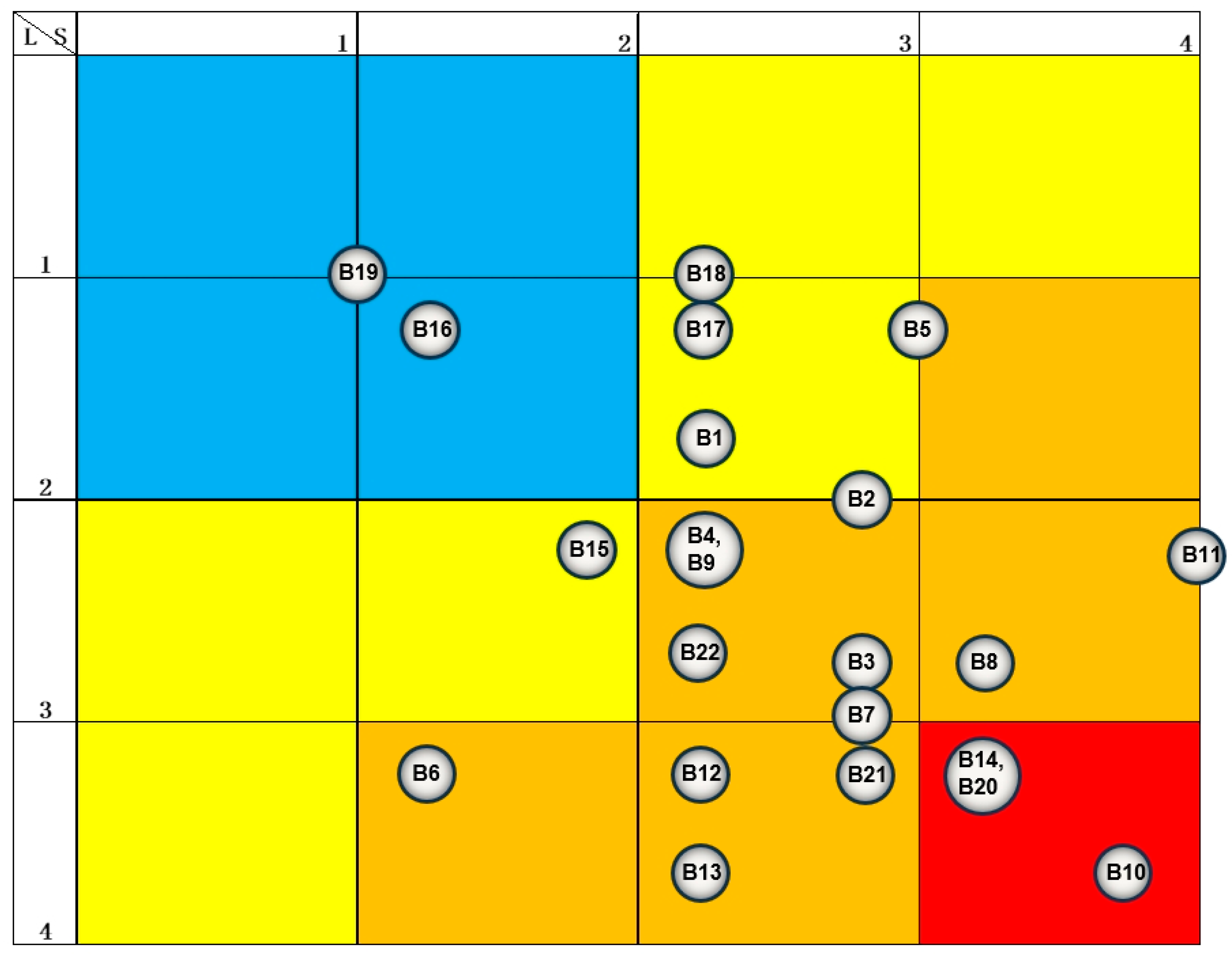
2.2. Risk Matrix Method (LS)

LS is a commonly used risk assessment method, mainly used to evaluate and identify potential hazards and their consequences. This method calculates the risk value (R) by multiplying the likelihood of an accident occurring by the severity of the consequences of the accident, as shown in Equation (8):
R = L × S
where L represents the likelihood or probability of the risk occurring, and S represents the severity of the consequences if the risk occurs.
The range of values and definitions of L and S are shown in Table 3. Based on the values of L and S, the risk is classified into four levels as shown in Table 3.

3. Risk Identification

3.1. Construction Workflow

The construction process for offshore wind power submarine cables comprises three main phases: preparation, cable laying, and construction ending. The workflow for offshore wind power submarine cable construction is illustrated in Figure 2.

3.2. Risk Identification

Risk identification was based on the findings from the offshore wind power construction safety risk assessment project, which involved consulting expert opinions. The risk factors were systematically categorized into equipment factors, worker factors, environmental factors, management factors, and third-party destruction factors.
(1)
Identification of equipment failure risk sources
Cable-laying vessel malfunction: Failures of key equipment on cable-laying vessels, such as engines or rudders, can lead to a loss of control. This loss of control may result in collisions or drifting, thereby endangering the safety of construction personnel and equipment.
Cable-burying machine malfunction: During cable burial operations, any abnormalities in the cable burial machine can not only affect the overall construction progress but also lead to sudden injury accidents.
Monitoring equipment failure: The failure of construction monitoring equipment, including cameras and sensors, can impede the effective monitoring of construction progress and safety conditions, thereby increasing the risk of accidents.
Communication equipment failure: The failure of on-site communication equipment may create communication barriers among construction workers, significantly impeding emergency response and coordination and adversely affecting construction efficiency.
The lifting lock being broken: Breakage of locks during lifting operations can cause lifting equipment to malfunction, potentially resulting in lifting accidents. Additionally, such failure may damage cables or other related equipment and pose a serious threat to the operators’ personal safety.
(2)
Identification of worker error risk sources
Illegal operation: Construction workers’ behaviors, driven by factors such as disregard for regulations, eagerness for results, and unauthorized deviations from established operating procedures and safety norms, significantly increase the likelihood of accidents.
Not wearing protective equipment: Construction workers’ failure to adhere to equipment and personal protective equipment regulations—such as not wearing safety helmets or seat belts—exacerbates safety risks and increases the likelihood of injury.
Low technical level: Operators must possess a thorough understanding and practical experience in key tasks such as cable laying and equipment maintenance. Insufficient skills or operational errors can result in equipment damage, construction delays, and even personal injury.
Weak safety awareness: During submarine cable construction, personnel must maintain a high level of vigilance. Weak safety awareness can lead to carelessness, risky operations, and other unsafe behaviors, thereby increasing the likelihood of accidents.
(3)
Identification of environmental impact risk sources
Complex submarine topography: The complexity and variability of seabed terrain significantly increase the difficulty and risk associated with submarine cable construction. Factors such as the seabed slope can substantially impact the stability of submarine pipelines, affecting both their design and their construction. These factors are critical considerations that must not be overlooked.
Extreme weather: Changes in sea conditions can also influence offshore wind power construction in multiple ways, including variations in wind speed, wind direction, wave height, and tides. Such changes may disrupt construction activities.
High-humidity air: Air humidity, particularly in electrified operation scenarios, poses additional risks. High humidity can lead to safety hazards such as equipment short-circuits and the electrocution of operators, thereby exacerbating construction risks.
Underwater obstacles: Underwater obstacles, such as fishing nets and marine life, represent another safety hazard. These obstacles not only complicate construction efforts but also have the potential to damage construction equipment.
Low underwater visibility: Low visibility underwater restricts operators’ ability to observe environmental conditions and assess operational states, thereby increasing the risk of construction accidents. In turbid waters, accurately determining the location and depth of cable laying becomes challenging, highlighting the need for advanced detection and positioning equipment to ensure construction accuracy.
(4)
Identification of management defect risk sources
The device not having undergone a security check and routine safety inspections of construction equipment not having been implemented: Equipment essential for construction that does not undergo the required cycles of safety inspection and maintenance may result in equipment failure or accidents.
Working without a license: Welders, diving operators, and other construction personnel currently lack the necessary licenses for their respective roles. The absence of formal qualifications for welders and diving operators may compromise project quality and elevate safety risks.
The construction plan not having been demonstrated and the construction program lacking expert review: Without detailed validation by experts, the program may contain design flaws or safety hazards, leading to frequent issues during construction.
Not a trial voyage: The route exploration and sea trial verification for the cable route have not been conducted. The absence of sea trial verification may result in unforeseen seabed geomorphology or underwater obstacles, thereby increasing the risk of damage to construction vessels and equipment.
Improper torsion bar and other non-standard components: Non-standardized construction of facilities, such as the retractor frame, can lead to instability of construction equipment and elevate the risk of accidents.
(5)
Identification of third-party destruction risk sources
Fishing operations: Fishing vessels utilizing trawls, gillnets, or other fishing gear during their operations may accidentally damage or break marine cables that are either already installed or being laid. Such incidents could compromise the integrity and normal functioning of the marine cables.
Ship’s anchor: When a vessel is anchored, contact between the anchor chain or anchor body and a submarine cable—particularly under conditions of low visibility or at night—can result in significant physical damage to the cable.
Fish bites: In certain marine areas, particularly those with high fish abundance or specific fish populations, fish may interact with the cable sheath due to curiosity or accidental feeding.

4. Safety Evaluation

Based on the risk identification results used to develop the AHP model, the safety evaluation model for offshore wind power submarine cable construction is illustrated in Figure 3. This model identifies five first-level risk factors and twenty-two secondary-level risk factors.

4.1. First-Level Risk Factor Evaluation

To develop effective risk reduction measures, calculate the risk priority of failure modes by assessing the severity, probability, and detection difficulty.

4.1.1. Severity Analysis

Five experts with relevant experience were invited to a consultation meeting and asked to complete a survey questionnaire regarding the severity of first-level risk factors in offshore wind power submarine cable construction. The resulting severity judgment matrix is presented in Table 4a–e.
The CR for all five judgment matrices was below 0.1, indicating that they passed the consistency test. The weights listed in Table 4a–e represent the scores assigned by each expert regarding the severity of first-level risk factors. Each expert’s weight was set at 0.2, based on a total possible score of 15 points. The severity ranking is calculated and displayed in Table 5.
Table 5 shows that higher scores corresponded to more severe consequences for each level of risk factor in offshore wind power submarine cable construction. Equipment failure had the highest score of 4.9479, signifying that its consequences were the most severe. In contrast, third-party destruction had the lowest score of 1.4961, indicating that its impact on offshore wind power submarine cable construction was relatively minor.

4.1.2. Probability Analysis

Five experts with relevant experience were invited to a consultation meeting and asked to complete a survey questionnaire regarding the probability of first-level risk factors in offshore wind power submarine cable construction. The resulting probability judgment matrix is presented in Table 6a–e.
The CR for all five judgment matrices was below 0.1, indicating that they passed the consistency test. The weights listed in Table 6a–e represent the scores assigned by each expert regarding the probability of first-level risk factors. Each expert’s weight was set at 0.2, based on a total possible score of 15 points. The probability ranking is calculated and displayed in Table 7.
Table 7 illustrates that a higher score corresponded to a greater frequency of occurrence for each first-level risk factor in offshore wind power submarine cable construction. The risk factor of environmental impact had the highest score of 4.9428, signifying the greatest frequency of its occurrence. Conversely, management defects had the lowest score of 1.2378, indicating the least frequent occurrence of such defects.

4.1.3. Detection Difficulty Analysis

Five experts with relevant experience were invited to a consultation meeting and asked to complete a survey questionnaire regarding the detection difficulty of first-level risk factors in offshore wind power submarine cable construction. The resulting detection difficulty judgment matrix is presented in Table 8a–e.
The CR for all five judgment matrices was below 0.1, indicating that they passed the consistency test. The weights listed in Table 8a–e represent the scores assigned by each expert regarding the detection difficulty of first-level risk factors. Each expert’s weight was set at 0.2, based on a total possible score of 15 points. The detection difficulty ranking is calculated and displayed in Table 9.
Table 9 shows that a higher score correlated with greater difficulty in identifying the first-level risk factors in offshore wind power submarine cable construction. The risk factor of third-party destruction had the highest score of 4.755, indicating that it was the most challenging to detect. Conversely, equipment failure had the lowest score of 1.7715, suggesting that it was the easiest to detect among the risk factors.

4.1.4. Evaluate Results

The risk evaluation values for the five first-level risk factors—equipment failure, worker error, environmental impact, management defects, and third-party destruction—were determined by multiplying the evaluation values for severity, probability, and detection difficulty. Table 10 presents the ranking of these risk evaluation values for the five risk factors.
A higher evaluation risk value indicated a greater priority for addressing risk factors. The evaluation results revealed that environmental factors posed the highest risk. During offshore wind power submarine cable construction, the aspect requiring the most attention was environmental impact, followed by third-party destruction and worker errors.

4.2. Secondary-Level Risk Factor Evaluation

Three experts with relevant experience were invited to a consultation meeting and asked to complete a survey on the likelihood and severity of secondary-level risk factors in offshore wind power submarine cable construction. The LS risk assessment derived from their evaluations is presented in Table 11.
Based on the evaluation results for each secondary-level risk factor, a four-color risk matrix chart was created, as shown in Figure 4. Figure 4 uses a color-coded risk matrix where red indicates major risks, orange denotes significant risks, yellow signifies general risks, and blue represents low risks.
Among the 22 secondary-level risk factors, there were 3 major risks, 13 significant risks, 4 general risks, and 2 low risks. The key aspects requiring additional measures during the construction of offshore wind power submarine cables were complex submarine topography, low underwater visibility, and fishing operations, followed by 13 significant risks.

5. Discussion

The primary risk factor in offshore wind power submarine cable construction is environmental, reflecting the significant challenges posed by hazardous sea conditions. Increased investment in safety measures related to environmental factors is essential for mitigating these risks.
The assessment of secondary risk factors identifies three major risks: complex submarine topography, low underwater visibility, and fishing operations. Two of these are environmental, while one pertains to third-party interference. Of the four general risks identified, one is related to equipment, and three are associated with management. Additionally, the two low-risk factors are also related to management. These findings demonstrate that the secondary-level risk factor assessment aligns with the primary-level risk factor assessment.
Based on the risk assessment results, the following specific recommendations are proposed to enhance the safety of offshore wind power submarine cable construction:
(1)
Environmental monitoring
Conducting thorough research and evaluation of the marine environment is essential before commencing offshore wind power submarine cable construction. This ensures the development of targeted construction plans and facilitates smooth project execution. During the preparation phase, it is crucial for the construction unit to collect comprehensive on-site data, including the submarine topography, underwater conditions, and offshore weather. Observation instruments should be installed to gather measured data, which must then be statistically analyzed to inform appropriate construction measures. Additionally, marine environmental research should account for the uncertainties associated with marine meteorological changes.
(2)
Third-party destruction protection
Physical barriers, such as buoys, nets, and warning posts, are installed to prevent vessels and fishing gear from making direct contact with cables and to ensure these barriers can withstand harsh sea conditions. Employ advanced monitoring technologies, including underwater cameras, sonar detectors, and satellite positioning systems, to continuously track the environment around the cables and provide immediate alerts for potential threats. Develop comprehensive emergency plans and response procedures, and assemble professional teams to promptly address issues and minimize accidental losses. Enhance the dissemination and enforcement of relevant laws and regulations, imposing strict penalties for violations. Conduct safety education and training for fishermen to improve their awareness and understanding of protection measures. Establish a collaborative mechanism with fisheries and maritime departments to jointly formulate and implement effective protection strategies.
(3)
Worker training
All workers must undergo rigorous training and education prior to assuming their positions to improve their skill levels and safety awareness. The integration of advanced technologies, such as intelligent monitoring systems and automatic detection of protective equipment, is essential for enhancing construction safety through technological advancements. Additionally, it is crucial to strengthen on-site supervision by appointing dedicated personnel to perform both regular and ad hoc inspections of the construction site, promptly identifying and rectifying any issues.
(4)
Equipment improvements
Regular inspections of key equipment are essential to ensure optimal working conditions. It is important to develop comprehensive emergency plans for potential equipment failures and to organize specialized personnel for repairs. Additionally, maintaining an adequate inventory of spare parts for critical equipment is crucial. To enhance the construction team’s responsiveness and capability to manage equipment failures, ongoing training and simulation drills should be conducted.
(5)
Improvement of the level of management
Water construction projects necessitate the provision of life-saving equipment and the issuance of appropriate notices. It is essential to rigorously enforce a personnel qualification review system to ensure that all construction personnel possess the necessary professional certificates and qualifications. On-site supervision and inspection should be reinforced by establishing a dedicated supervision team responsible for both regular and ad hoc inspections of critical processes. Additionally, preconstruction training and briefings must be systematically strengthened. Implementing a robust reward and punishment mechanism is also crucial: violations should be addressed with severity, while outstanding performance should be duly recognized and rewarded.
As the risk factor increases, it becomes crucial to implement priority measures and increase safety investments. These steps can decrease the incidence of construction accidents and enhance overall safety.

6. Conclusions

Offshore wind power construction units can utilize the methods outlined in this paper to identify and assess risk factors and implement targeted safety measures based on these evaluations to enhance the safety of offshore wind power projects.
(1) The offshore wind power submarine cable construction process comprises three main phases: preparation, cable laying, and construction ending. Through project research and expert consultations, 5 primary risk factors and 22 secondary risk factors were identified.
(2) The AHP was employed to rank the primary risk factors based on severity, probability, and detection difficulty. The most significant risk identified was environmental impact, followed by third-party interference and worker error. The LS method was used to rank the secondary risk factors, categorizing them into 3 major risks, 13 significant risks, 4 general risks, and 2 low risks.
(3) Key areas requiring further attention in offshore wind power submarine cable construction include complex submarine topography, low underwater visibility, and fishing operations, with 13 significant risk factors also warranting consideration.

Author Contributions

Conceptualization, Q.Z. and H.H.; methodology, H.X.; software, E.Z.; validation, X.T., S.F. and Z.L.; investigation, J.Z. and E.Z.; resources, Q.Z.; data curation, H.X.; writing—original draft preparation, S.F.; writing—review and editing, D.Y.; visualization, D.Y.; supervision, D.Y.; project administration, Q.Z.; funding acquisition, Z.L. All authors have read and agreed to the published version of the manuscript.

Funding

This research was funded by the Science and Technology Project of POWERCHINA (No. DJ-ZDXM-2023-50).

Institutional Review Board Statement

Not applicable.

Informed Consent Statement

Not applicable.

Data Availability Statement

The data presented in this study are available on request from the corresponding author.

Conflicts of Interest

Authors Qiang Zhang, Hui Huang, and Hao Xu were employed by the Powerchina Huadong Engineering Co., Ltd. and Powerchina Zhejiang Huadong Engineering Consulting Co., Ltd. The remaining authors declare that the research was conducted in the absence of any commercial or financial relationships that could be construed as a potential conflict of interest.

References

  1. Martinez, A.; Iglesias, G. Global wind energy resources decline under climate change. Energy 2024, 288, 129765. [Google Scholar] [CrossRef]
  2. Fang, S.-H.; Zhu, H.-Q.; Yang, D.-D.; Yu, J.-X.; Wang, J.; Hu, L.-T. Microscopic investigation of the effect of uniaxial stress on the structure of pore-fissure system and methane adsorption in lean coal. Energy 2024, 288, 129837. [Google Scholar] [CrossRef]
  3. Yang, D.-D.; Qin, Y.-J.; Xu, Y.-R.; Xing, K.-X.; Chen, Y.-J.; Jia, X.-P.; Aviso, K.-B.; Tan, R.-R.; Wang, B.-H. Sequestration of carbon dioxide from the atmosphere in coastal ecosystems: Quantification, analysis, and planning. Sustain. Prod. Consum. 2024, 47, 413–424. [Google Scholar] [CrossRef]
  4. Joyce, L.F.Z. Global Wind Report 2024; Global Wind Energy Council: Brussels, Belgium, 2024. [Google Scholar]
  5. Karayel, G.K.; Dincer, I. A study on green hydrogen production potential of Canada with onshore and offshore wind power. J. Clean. Prod. 2024, 437, 140660. [Google Scholar] [CrossRef]
  6. Wang, W.; Huang, H.; Peng, X.; Wang, Z.; Zeng, Y. Utilizing support vector machines to foster sustainable development and innovation in the clean energy sector via green finance. J. Environ. Manag. 2024, 360, 121225. [Google Scholar] [CrossRef]
  7. Zhao, Y.; Xue, Y.; Gao, S.; Wang, J.; Cao, Q.; Sun, T.; Liu, Y. Computation and Analysis of an Offshore Wind Power Forecast: Towards a Better Assessment of Offshore Wind Power Plant Aerodynamics. Energies 2022, 15, 4223. [Google Scholar] [CrossRef]
  8. Jia, Y.; Ren, B.; Li, Q.; Wang, C.; Wang, D.; Zou, X. An Integrated Scheme for Forecasting and Controlling Ramps in Offshore Wind Farms Considering Wind Power Uncertainties during Extreme Storms. Electronics 2023, 12, 4443. [Google Scholar] [CrossRef]
  9. Rebecca, W.F.Z. Global Offshore Wind Report 2024; Global Wind Energy Council: Brussels, Belgium, 2024. [Google Scholar]
  10. Wang, J.-Z.; Qin, S.-S.; Jin, S.-Q.; Wu, J. Estimation methods review and analysis of offshore extreme wind speeds and wind energy resources. Renew. Sustain. Energy Rev. 2015, 42, 26–42. [Google Scholar] [CrossRef]
  11. Zhang, X.; Sun, L.-P.; Sun, H.; Guo, Q.; Bai, X. Floating offshore wind turbine reliability analysis based on system grading and dynamic FTA. J. Wind Eng. Ind. Aerodyn. 2016, 154, 21–33. [Google Scholar] [CrossRef]
  12. Johnston, A.; Cook, A.; Wright, L.; Humphreys, E.; Burton, N. Modelling flight heights of marine birds to more accurately assess collision risk with offshore wind turbines. J. Appl. Ecol. 2014, 51, 31–41. [Google Scholar] [CrossRef]
  13. Wu, Y.-N.; Zhang, T. Risk assessment of offshore wave-wind-solar-compressed air energy storage power plant through fuzzy compre-hensive evaluation model. Energy 2021, 223, 120057. [Google Scholar] [CrossRef]
  14. Lian, J.-J.; Hou, G.; Cai, O.; Xu, K. Assessing the life cycle risks of offshore wind turbines with suction bucket foundations. J. Clean. Prod. 2022, 362, 132366. [Google Scholar] [CrossRef]
  15. Cheng, M.-Y.; Wu, Y.-F. Investment Evaluation and Partnership Selection Model in the Offshore Wind Power Underwater Foundations Industry. J. Mar. Sci. Eng. 2021, 9, 1371. [Google Scholar] [CrossRef]
  16. Kazmi, S.; Laneryd, T.; Giannikas, K.; Ahrenfeldt, S.; Sørensen, T.; Olesen, T.; Holbøll, J. Cost optimized dynamic design of offshore windfarm transformers with reliability and contingency considerations. Int. J. Electr. Power Energy Syst. 2021, 128, 106684. [Google Scholar] [CrossRef]
  17. Soukissian, T.; Karathanasi, F.; Zaragkas, D. Exploiting offshore wind and solar resources in the Mediterranean using ERA5 reanalysis data. Energy Convers. Manag. 2021, 237, 114092. [Google Scholar] [CrossRef]
  18. Kuang, J.; Chen, G.; Yuan, Z.; Qi, X.; Yu, Q.; Liu, Z. Dynamic Interactions of a Cable-Laying Vessel with a Submarine Cable during Its Landing Process. J. Mar. Sci. Eng. 2022, 10, 774. [Google Scholar] [CrossRef]
  19. Dong, T.; Brakelmann, H.; Anders, G.J. Analysis method for the design of long submarine cables. Renew. Sustain. Energy Rev. 2023, 171, 113029. [Google Scholar] [CrossRef]
  20. Perveen, R.; Kishor, N.; Mohanty, S.R. Off-shore wind farm development: Present status and challenges. Renew. Sustain. Energy Rev. 2014, 29, 780–792. [Google Scholar] [CrossRef]
  21. Zhu, Z.; Liang, Y.; Chen, L.; Liu, Y.; Du, Y. Study on AC interference law of high voltage AC cable to submarine pipeline and safe distance. Mater. Corros. 2022, 74, 560–575. [Google Scholar] [CrossRef]
  22. Cazzaro, D.; Koza, D.F.; Pisinger, D. Combined layout and cable optimization of offshore wind farms. Eur. J. Oper. Res. 2023, 311, 301–315. [Google Scholar] [CrossRef]
  23. Choi, J.-K.; Yokobiki, T.; Kawaguchi, K. ROV-Based Automated Cable-Laying System: Application to DONET2 Installation. IEEE J. Ocean. Eng. 2018, 43, 665–676. [Google Scholar] [CrossRef]
  24. Lux, J.; Olschewski, M.; Schafer, P.; Hill, W. Real-Time Determination of Depth of Burial Profiles for Submarine Power Cables. IEEE Trans. Power Deliv. 2019, 34, 1079–1086. [Google Scholar] [CrossRef]
  25. Pérez-Rúa, J.A.; Lumbreras, S.; Ramos, A.; Cutululis, N.A. Reliability-based topology optimization for offshore wind farm collection system. Wind Energy 2021, 25, 52–70. [Google Scholar] [CrossRef]
  26. Mamatsopoulos, V.A.; Michailides, C.; Theotokoglou, E.E. An Analysis Tool for the Installation of Submarine Cables in an S-Lay Configuration Including “In and Out of Water” Cable Segments. J. Mar. Sci. Eng. 2020, 8, 48. [Google Scholar] [CrossRef]
  27. Cui, D.-h.; Zhang, X.-y. Application of gray analytic hierarchy process in project risk evaluation. In Proceedings of the 2009 International Conference on Artificial Intelligence and Computational Intelligence, Shanghai, China, 7–8 November 2009; pp. 592–594. [Google Scholar] [CrossRef]
  28. Díaz, H.; Teixeira, A.P.; Guedes Soares, C. Application of Monte Carlo and Fuzzy Analytic Hierarchy Processes for ranking floating wind farm locations. Ocean Eng. 2022, 245, 110453. [Google Scholar] [CrossRef]
  29. Jia, P.; Lv, J.; Sun, W.; Jin, H.; Meng, G.; Li, J. Modified analytic hierarchy process for risk assessment of fire and explosion accidents of external floating roof tanks. Process Saf. Prog. 2023, 43, 9–26. [Google Scholar] [CrossRef]
  30. Gass, S.I. Model World: The Great Debate—MAUT versus AHP. Interfaces 2005, 35, 308–312. [Google Scholar] [CrossRef]
  31. Wang, Y.-M.; Chin, K.-S.; Leung, J.P.-F. A note on the application of the data envelopment analytic hierarchy process for supplier selection. Int. J. Prod. Res. 2009, 47, 3121–3138. [Google Scholar] [CrossRef]
  32. Wang, F.; Lu, Y.; Li, J.; Ni, J. Evaluating Environmentally Sustainable Development Based on the PSR Framework and Variable Weigh Analytic Hierarchy Process. Int. J. Environ. Res. Public Health 2021, 18, 2836. [Google Scholar] [CrossRef]
  33. Zhao, Y.; Liu, H.; Qu, W.; Luan, P.; Sun, J. Research on Geological Safety Evaluation Index Systems and Methods for Assessing Underground Space in Coastal Bedrock Cities Based on a Back-Propagation Neural Network Comprehensive Evaluation–Analytic Hierarchy Process (BPCE-AHP). Sustainability 2023, 15, 8055. [Google Scholar] [CrossRef]
  34. Zhao, D.; Wang, Z.-R.; Song, Z.-Y.; Guo, P.-K.; Cao, X.-Y. Assessment of domino effects in the coal gasification process using Fuzzy Analytic Hierarchy Process and Bayesian Network. Saf. Sci. 2020, 130, 104888. [Google Scholar] [CrossRef]
Figure 1. New offshore wind installations in China and the world (excluding China).
Jmse 12 01718 g001
Figure 2. Offshore wind power submarine cable construction workflow.
Jmse 12 01718 g002
Figure 3. AHP model.
Jmse 12 01718 g003
Figure 4. Four-color chart of the risk matrix.
Jmse 12 01718 g004
Table 1. Meaning of scale.
ScaleMeaning
1Two factors are equally important
2The former is slightly more important than the latter
3The former is significantly more important than the latter
4The former is strongly more important than the latter
5The former is extremely more important than the latter
ReciprocalThe scale of factor Ai to factor Aj is aij, and vice versa, 1/aij
Table 2. RI values corresponding to each order matrix.
n123456789101112131415
RI000.520.891.121.251.351.401.451.491.521.541.561.581.59
Table 3. The values of L, S, and R.
SymbolValueMeaning
L1Almost never occurs
2Rarely occurs
3Occasionally occurs
4Frequent occurrence
S1Almost no loss
2Minor loss
3Moderate loss
4Serious losses
RL < 2 and S < 2Low risk
L < 1 and 2 ≤ S; 1 ≤ L < 2 and 2 ≤ S < 3; 2 ≤ L < 3 and S < 2; 3 ≤ L and S < 1General risk
1 ≤ L < 2 and 3 ≤ S; 2 ≤ L <3 and 2 ≤ S; 3 ≤ L and 1 ≤ S < 3Significant risk
3 ≤ L and 3 ≤ SMajor risks
Table 4. (a) Expert 1’s judgment matrix. (b) Expert 2’s judgment matrix. (c) Expert 3’s judgment matrix. (d) Expert 4’s judgment matrix. (e) Expert 5’s judgment matrix.
(a)
Matrix 1A1A2A3A4A5WeightIndex
A1122440.3936λmax = 5.056
CI = 0.014
CR = 0.012
A21/211320.2135
A31/211220.1968
A41/41/31/211/20.0810
A51/41/21/2210.1151
(b)
Matrix 2A1A2A3A4A5WeightIndex
A1132450.4146λmax = 5.139
CI = 0.035
CR = 0.031
A21/311/2330.1799
A31/221240.2423
A41/41/31/2120.1011
A51/51/31/41/210.0621
(c)
Matrix 3A1A2A3A4A5WeightIndex
A1121/3120.1870λmax = 5.189
CI = 0.047
CR = 0.042
A21/211/21/230.1526
A3321240.3786
A4121/2120.1999
A51/21/31/41/210.0818
(d)
Matrix 4A1A2A3A4A5WeightIndex
A1121/3420.2335λmax = 5.160
CI = 0.040
CR = 0.036
A21/211/3220.1551
A3331430.4210
A41/41/21/411/20.0732
A51/21/21/3210.1173
(e)
Matrix 5A1A2A3A4A5WeightIndex
A1152430.4206λmax = 5.193
CI = 0.048
CR = 0.043
A21/511/41/21/30.0619
A31/241320.2654
A41/421/3120.1296
A51/331/21/210.1224
Table 5. Calculate severity.
Expert 1Expert 2Expert 3Expert 4Expert 5Mean ValueCalculated Value
A10.39360.41460.18700.23350.42060.32984.9479
A30.19680.24230.37860.42100.26540.30084.5123
A20.21350.17990.15260.15510.06190.15262.2890
A40.08100.10110.19990.07320.12960.11701.7544
A50.11510.06210.08180.11730.12240.09971.4961
Table 6. (a) Expert 1’s judgment matrix. (b) Expert 2’s judgment matrix. (c) Expert 3’s judgment matrix. (d). Expert 4’s judgment matrix. (e) Expert 5’s judgment matrix.
(a)
Matrix 1A1A2A3A4A5WeightIndex
A111/31/421/20.1001λmax = 5.065
CI = 0.016
CR = 0.015
A2311/2420.2642
A3421530.4189
A41/21/41/511/20.0679
A521/21/3210.1489
(b)
Matrix 2A1A2A3A4A5WeightIndex
A111/21/31/21/20.0937λmax = 5.276
CI = 0.069
CR = 0.062
A2211/331/20.1654
A3331520.4005
A421/31/511/40.0932
A5221/2410.2471
(c)
Matrix 3A1A2A3A4A5WeightIndex
A111/31/41/21/50.0627λmax = 5.072
CI = 0.018
CR = 0.016
A231121/30.1852
A341131/20.2322
A421/21/311/40.0993
A5532410.4206
(d)
Matrix 4A1A2A3A4A5WeightIndex
A111/21/311/20.1036λmax = 5.086
CI = 0.021
CR = 0.019
A2211/2420.2524
A3321530.4079
A411/41/511/20.0806
A521/21/3210.1555
(e)
Matrix 5A1A2A3A4A5WeightIndex
A111/31/221/30.1071λmax = 5.262
CI = 0.065
CR = 0.058
A2311420.3250
A321121/30.1881
A41/21/41/211/40.0716
A531/23410.3082
Table 7. Calculate probability.
Expert 1Expert 2Expert 3Expert 4Expert 5Mean ValueCalculated Value
A30.41890.40050.23220.40790.18810.32954.9428
A50.14890.24710.42060.15550.30820.25613.8409
A20.26420.16540.18520.25240.32500.23843.5766
A10.10010.09370.06270.10360.10710.09341.4016
A40.06790.09320.09930.08060.07160.08251.2378
Table 8. (a) Expert 1’s judgment matrix. (b) Expert 2’s judgment matrix. (c) Expert 3’s judgment matrix. (d) Expert 4’s judgment matrix. (e) Expert 5’s judgment matrix.
(a)
Matrix 1A1A2A3A4A5WeightIndex
A1121/31/21/20.1231λmax =5.194
CI = 0.049
CR = 0.043
A21/211/31/21/30.0855
A3331320.3761
A4221/311/30.1511
A5231/2310.2646
(b)
Matrix 2A1A2A3A4A5WeightIndex
A111/21/21/41/50.0726λmax =5.180
CI = 0.045
CR = 0.040
A2211/21/21/30.1173
A322121/20.2216
A4421/211/30.1842
A5532310.4043
(c)
Matrix 3A1A2A3A4A5WeightIndex
A111/41/21/21/50.0707λmax = 5.138
CI = 0.034
CR = 0.031
A241121/30.2006
A321131/20.2057
A421/21/311/40.1007
A5532410.4223
(d)
Matrix 4A1A2A3A4A5WeightIndex
A111/31/21/21/40.0792λmax = 5.101
CI = 0.025
CR = 0.023
A231321/20.2665
A321/311/21/30.1129
A421/2211/20.1715
A5423210.3699
(e)
Matrix 5A1A2A3A4A5WeightIndex
A11231/220.2449λmax = 5.131
CI = 0.033
CR = 0.029
A21/211/21/320.1617
A31/31/211/31/20.0863
A4233130.3832
A51/21/221/310.1239
Table 9. Calculate detection difficulty.
Expert 1Expert 2Expert 3Expert 4Expert 5Mean ValueCalculated Value
A50.26460.40430.42230.36990.12390.31704.7550
A30.37610.22160.20570.11290.08630.20053.0078
A40.15110.18420.10070.17150.38320.19812.9721
A20.08550.11730.20060.26650.16170.16632.4948
A10.12310.07260.07070.07920.24490.11811.7715
Table 10. Evaluation risk value.
SeverityProbabilityDetection DifficultyEvaluation Risk Value
A34.51234.94283.007867.0842
A51.49613.84094.755027.3239
A22.28903.57662.494820.4245
A14.94791.40161.771512.2853
A41.75441.23782.97216.4543
Table 11. LS risk assessment.
First-Level Risk FactorSecondary-Level Risk FactorLSR
L1L2L3LS1S2S3S
A1B11221.72322.33.9
B22222.03232.75.3
B33232.73322.77.1
B42322.32232.35.4
B51211.34233.04.0
A2B64333.32111.34.4
B73243.02332.78.0
B82332.74333.38.9
B93222.32322.35.4
A3B104433.74343.713.4
B113222.34444.09.3
B123433.32322.37.8
B133443.73222.38.6
B143343.33433.311.1
A4B153222.32121.73.9
B161211.31211.31.8
B171121.32412.33.1
B181111.02322.32.3
B191111.01111.01.0
A5B203343.34333.311.1
B213433.33322.78.9
B223232.73222.36.2
Disclaimer/Publisher’s Note: The statements, opinions and data contained in all publications are solely those of the individual author(s) and contributor(s) and not of MDPI and/or the editor(s). MDPI and/or the editor(s) disclaim responsibility for any injury to people or property resulting from any ideas, methods, instructions or products referred to in the content.

