Article

Coupled Modeling of Sea Surface Launch Flow and Multi-Body Motion

1
School of Aerospace Engineering, Beijing Institute of Technology, Beijing 100081, China
2
Institute of Systems of Engineering, China Academy of Engineering Physics, Mianyang 621999, China
3
Shock and Vibration of Engineering Materials and Structure Key Laboratory of Sichuan Province, Mianyang 621999, China
*
Author to whom correspondence should be addressed.
J. Mar. Sci. Eng. 2024, 12(10), 1736; https://doi.org/10.3390/jmse12101736
Submission received: 18 July 2024 / Revised: 12 September 2024 / Accepted: 16 September 2024 / Published: 2 October 2024
(This article belongs to the Section Ocean Engineering)

Abstract

:
To simulate the launching process of missile complex flow, movement, and constraint states, a multifield coupling model is put forward based on a computational fluid dynamics (CFD) method. In this coupled model, a CFD method is used to solve the three-dimensional compressible transient flow, and the six-degree motion of the launching platform is considered, and the virtual contact method is used to deal with the constraint states of the guideway and the slider. The active force and moment are applied to the launching platform to simulate its rolling, pitching, and heaving motions under the 5-level waves. Collision detection is carried out through the minimum clearance distance between the slider and the guideway, and the contact force is handled by a modified Herz collision model. In the problem of launching a missile from the water surface, the change characteristics of the flow field, the load response characteristics, and the relative motion laws of the missile and the launching platform during the catapulting process are investigated. The results show that the motion laws of the projectile and the launch tube in the constrained direction are the same, and the established coupling model is able to simulate the launch separation process of the missile in the constrained state. In addition, the effect of wind load on the missile ejection process is analyzed using the coupled model.

1. Introduction

Sea surface launched missiles play an important role in modern warfare. In the process of launching the missile out of the tube, the body of the missile is subjected to the joint action of many kinds of loads, including the thrust of the ejection gases, the resistance of the ambient fluid, and the binding force on the body of the missile by the guide rail of the launch tube [1,2]. In addition, in the actual launching process, the launching platform is often in motion, and the launching of the projectile will be affected by lateral winds as well as waves. These effects will increase the lateral collision between the projectile and the launch tube, which will form a complex force state between the projectile and the launch tube. In-depth study of the evolution characteristics of the flow field during the launching process and the restraining load characteristics between the projectile and the launch tube play an important role in improving the structure of the launch tube, which has received extensive attention from researchers [3].
The separation process of a missile launched from a dynamic platform is a multi-rigid-body dynamics problem coupled with unsteady flow and rigid-body motion. It includes air launch, underwater platform launch, carrier launch, and surface platform launch [4,5,6]. Launch vehicles generally use multi-stage boosting to increase the payload capacity. Among them, the separation dynamics of the rocket and booster have received attention from many researchers [7,8,9]. Jafari et al. [10] used the separation spring method to establish a coupled motion and flow solution to simulate the separation process of the rocket and booster as well as the aerodynamic effects. In addition to the multi-stage rocket separations described above, common airborne separation problems include the separation of airplanes from missiles. Olejnik et al. [11] studied the separation process of an aircraft and an externally connected missile by CFD method and analyzed the separation safety. Tian et al. [12] studied a numerical method for multi-target collision separation using an impulse-based approach to characterize collisions between rigid bodies. Pan et al. [13] investigated the effects of different external disturbances on the horizontal backward separation of airborne missiles of large transport aircraft. Tian et al. [14] investigated the effect of aerodynamic elasticity on the separation of a missile from its inner compartment based on the CFD method and used a spring tension deformation method to characterize the structural deformation.
During the separation process described above, if a collision occurs, the separation is not considered safe. However, in separation problems such as underwater launching or surface platform launching, the missile motion is constrained by the launching cylinder, and collision between two objects is allowed. The missile is coupled by hydrodynamic forces as well as the supporting structure inside the tube during underwater launch. Complex deformation response and transverse vibration are involved [15,16]. Shang et al. [17] developed a kinetic model for the underwater vertical launching process. The effects of lateral force and adapter compression stiffness on the missile ejection process were mainly investigated. Liu et al. [18] investigated the launching process of a missile from an underwater fixed platform based on a numerical simulation method. The constraint effect of the launch tube on the missile was characterized by the method of nonlinear spring deformation response. However, most of these methods are based on fixed launching platforms, which cannot effectively characterize the constraint effect between the dynamic launching platform and the missile.
Carrier launches have one thing in common with launches from surface platforms: the launch platform is in motion and subject to complex forces from the water. The relative motion process of the missile and launch platform directly affects the ballistic performance within the launch tube ejection. Zeng et al. [19] used numerical simulation to investigate the ballistic properties and influencing factors of the uplifted launch tube internal ballistic properties. However, only the motion of the missile along the axial direction of the launch tube was considered. Lu et al. [20] and Liu et al. [21] investigated the effects of complex sea conditions on the water-surface launch separation characteristics of missile dynamic platforms. The article considered the effect of the adapter on the missile but did not consider the effect of gas on the launch separation process. For surface launch platforms, researchers focus more on the effect of ship motion on the missile’s attitude out of the tube [22]. There is a lack of discussion on the effect of gas generation.
With both the launch platform and the projectile in motion, the ejection gas flow can significantly affect the internal trajectory and the initial trajectory of the projectile. Liang et al. [23] investigated the jet dynamics during the thermal launch of a missile from a launch box, with particular attention to the effect of missile attitude deflection on the flow field distribution inside the box. Lee et al. [24] demonstrated the ejection effect formed by the nozzle wake in the launching box during missile launch and the unbalanced torque enhanced by missile deflection through numerical studies. Turbulent free jets and their interaction with passive scalars are also critical to the flow. Borynyak and Hrebtov [25] investigated turbulent diffusion and vortex fragmentation generated by a rotating nozzle, revealing the turbulent structure and the distribution characteristics of the passive scalar concentration at different numbers of rotations. Sahebjam et al. [26] demonstrated that the uniformly isotropic surrounding turbulence is enhanced by enhanced jet interface modulation, drift of the jet, and doping of the turbulent ambient fluid, which accelerates the destruction of the jet structure. These works are crucial for understanding the gas dynamics of missiles when launched from dynamic platforms such as ships or submarines.
In order to better analyze the load response characteristics of a moving platform when launching a projectile, a constraint model is needed to characterize the constraint state between the projectile and the guide rail. In this paper, a guide rail slider constraint model based on virtual contact is proposed on the basis of computational fluid dynamics. Combined with the gas flow as well as the projectile motion, a coupled computational model of surface launch flow and motion constraints considering the motion of the launch platform is established. The launch separation characteristics of the projectile are investigated for the effects of specific sea conditions and wind loads. The numerical method in this paper can provide a reference for the research and design of a launch separation system for moving platforms.

2. Numerical Methods

2.1. The Launching Process and Coordinates Arrangement

The water surface launch platform and the missile are moved by the combined action of the ejector gas and the waves, respectively. The missile can only move in the direction of the axis of the launching tube by means of a guide slide between the two. Throughout the launch separation process, the object is mainly subjected to the ejection pressure loads generated by the power unit, the ambient fluid loads, and the restraining loads of the guides and slides. In the coupled model, the ejection pressure loads and ambient fluid loads are obtained by flow calculation and surface pressure integration. The restraining load on the guideway is calculated by combining the relative motion parameters of the missile and the launch tube.
The force state and coordinate arrangement of the missile in the coupled model are shown in Figure 1. The model adopts a multi-slider launch separation method; the relative positions of the slider and the missile remain unchanged during the stage of movement in the missile tube. The model mainly considers the following coordinate systems: One is the inertial system O x y z , which does not move with the object. The origin of the coordinates is located in the center of the mouth of the cylinder. Second, the cylinder system O 1 x 1 y 1 z 1 , established in the launch platform center of mass position, with the platform movement. The third is the missile system O 2 x 2 y 2 z 2 , established at the missile center of mass position, moving with the missile. During launch, the projectile is subjected to fluid forces F fluid _ m and moments M fluid _ m (including crosswind and ejection loads), gravity G m , and constraint forces F m and moments M m . The cylinder is subjected to fluid force F fluid _ v and moment M fluid _ v , gravity G v , the restraining force F v , and moment M v . The missile is ejected out of the cylinder in the O 1 x 1 along the cylinder system in the rail-slider constrained state shown in Figure 1.

2.2. Flow Control Equations and Solution Methods

During the ejection of the projectile, the fluid undergoes a significant pressure change and is therefore assumed to be a compressible fluid. Meanwhile, the missile leaves the cylinder rapidly and the viscous effect of the gas is not negligible, so the Navier–Stokes (NS) equations are used to deal with the effect of viscous forces. In addition, the fluid velocity is much smaller than the speed of sound, and relativistic effects are neglected. In this water surface missile ejection study, the flow control equations consists of a continuity equation, the momentum equation, and an energy equation. The control equations are as follows:
ρ t + ( ρ u ) = 0
( ρ u ) t + ( ρ u u ) = p + τ + F
( ρ E ) t + ( u ( ρ E + p ) ) = [ κ T + ( τ u ) ]
where ρ is the fluid density, and u represents the velocity vector. p is the pressure, and τ is the stress tensor. E is the internal energy per unit mass. κ is the thermal conductivity. T is the average temperature. F represents the external force acting on the fluid.
In the study of water surface ejected projectiles, OpenFOAM v2012 is used for flow simulation calculations. The coupled model is calculated by solving the flow control equations using the Reynolds-averaged Navier-Stokes equations (RANS). As the missile undergoes high-speed motion during ejection, the fluid enters a state of turbulence. The RNS k-ε model is used to describe the turbulence, and standard wall function is used to solve the turbulence in the near-wall region. The finite volume method is used to discretize and solve the flow Reynolds mean equation. A coupled pressure–velocity coupling algorithm is used to solve the momentum equations, with the density and momentum terms following a first-order upwind format and the time discretization term based on a first-order implicit format. The turbulence model is obtained by solving the transport equation containing the turbulent kinetic energy and its dissipation rate to obtain the turbulent viscosity coefficient, denoted as
μ t = ρ C μ k 2 ε
ρ k t + ( ρ u j k ) x j = x j μ + μ t σ k k x j + G k + G b ρ ε Y M
ρ ε t + ρ u j ε x j = x j μ + μ t σ ε ε x j + C ε 1 ε k G k ρ C ε 2 ε 2 k + C ε 1 ε k C ε 3 G b
where k is the turbulent kinetic energy and ε is the dissipation rate of the turbulent velocity pulsation. μ t is the turbulent viscosity coefficient. G k is the turbulent kinetic energy generation term due to the velocity gradient, G b is the turbulent kinetic energy generation term due to the buoyancy force, and Y M is the turbulent dissipation due to the change in viscous forces. σ k and σ ε are the Turbulent Prandtl numbers of the transported properties. C ε 1 = 1.44 , C ε 2 = 1.92 , C ε 3 = 1.0 , σ k = 1.3 , and σ ε = 1.0 .

2.3. Constrained Load Solving Method

The constraint load between the slider of the missile and the tube guide in the model is calculated based on the virtual contact method. In the inertial coordinate system, the center of mass of the launching cylinder is ( x v , y v , z v ) and the angular velocity of rotation around the three axes is ω x 1 , ω y 1 , ω z 1 . The missile center of mass is ( x m , y m , z m ) and the angular velocity of rotation around the three axes is ω x 2 , ω y 2 , ω z 2 . In the missile system, the coordinate of the center point of the missile section where the slider is located is ( x i , y i , z i ) , i = 1 , 2 , N . In this paper, two sets of sliders ( N = 2) are arranged axially on the projectile body. In order to accurately describe the motion state of the object, the quaternion method is used to solve the attitude.
The constraint direction is defined by the cylinder system, while the kinetic equations are defined according to the inertial system. Therefore, it is necessary to combine the quaternion transformation matrix to perform the transformation between the inertial system and the cylinder system. The quaternion conversion matrix is as follows:
Q m = q m 0 2 + q m 1 2 q m 2 2 q m 3 2 2 q m 1 q m 2 2 q m 0 q m 3 2 q m 0 q m 2 + 2 q m 1 q m 3 2 q m 1 q m 2 + 2 q m 0 q m 3 q m 0 2 + q m 2 2 q m 1 2 q m 3 2 2 q m 2 q m 3 2 q m 0 q m 1 2 q m 1 q m 3 2 q m 0 q m 2 2 q m 2 q m 3 + 2 q m 0 q m 1 q m 0 2 + q m 3 2 q m 1 2 q m 2 2
Q v = q v 0 2 + q v 1 2 q v 2 2 q v 3 2 2 q v 1 q v 2 2 q v 0 q v 3 2 q v 0 q v 2 + 2 q v 1 q v 3 2 q v 1 q v 2 + 2 q v 0 q v 3 q v 0 2 + q v 2 2 q v 1 2 q v 3 2 2 q v 2 q v 3 2 q v 0 q v 1 2 q v 1 q v 3 2 q v 0 q v 2 2 q v 2 q v 3 + 2 q v 0 q v 1 q v 0 2 + q v 3 2 q v 1 2 q v 2 2
where Q m is the quaternion matrix for the conversion from the elastic system to the inertial system. Q v is the quaternion matrix for the conversion of the cylinder system to the inertial system. q m 0 , q m 1 , q m 2 , and q m 3 are the quaternion coefficients of the missile system, which are calculated as shown in Equation (9). Similarly, the cylinder coordinate system quaternion coefficients are calculated in this way. q v 0 , q v 1 , q v 2 , and q v 3 are the quaternion coefficients of the cylinder coordinate system, respectively.
d d t q m 0 q m 1 q m 2 q m 3 = 1 2 0 ω x 1 ω y 1 ω z 1 ω x 1 0 ω z 1 ω y 1 ω y 1 ω z 1 0 ω x 1 ω z 1 ω y 1 ω x 1 0 q m 0 q m 1 q m 2 q m 3
The distance between the point of the sliding block under the inertial system and the center of mass of the missile is expressed as follows:
Δ x 0 i = Q m x 2 i , i = 1 , 2 , N
x 0 i = Δ x 0 i + x m , i = 1 , 2 , N
x 1 i = Q v Τ ( x 0 i x v ) , i = 1 , 2 , N
where Δ x 0 i is the distance between the point of the slider and the center of mass of the missile in the inertial system; it represents the distance in three directions ( Δ x 0 i , Δ y 0 i , and Δ z 0 i , respectively). x 2 i represents the coordinates of the position of the slider under the missile system ( x 2 i , y 2 i , and z 2 i , respectively). x 0 i represents the coordinates of the position of the slider in the inertial system ( x 0 i , y 0 i , and z 0 i , respectively). x m represents the position coordinates of the body’s center in the inertial system ( x m , y m , and z m , respectively). x 1 i represents the coordinates of the position of the slider under the cylinder system ( x 1 i , y 1 i , and z 1 i , respectively). x v represents the positional coordinates of the cylinder center of mass in the inertial system ( x v , y v , and z v , respectively). The subscript 0 indicates the inertial system, the subscript 1 indicates the cylinder system, and the subscript 2 indicates the missile system. The subscripts i and N represent the number of the slider and the number of sliders, respectively.
The motion of the missile in the tube is a composite motion of a rigid body. According to the velocity synthesis theorem for points, the velocity of the slider in the inertial system with respect to the center of mass of the cylinder is obtained as follows:
v 0 i = v o 2 + ω 2 r o 2 0 i v o 1 ω 1 r o 1 0 i
Δ v 1 i = Q v T v 0 i
where v o 1 represents the velocity vector of the cylinder center of mass in an inertial system ( u o 1 , v o 1 , and w o 1 , respectively). v o 2 represents the velocity vector of the projectile center of mass in the inertial system ( u o 2 , v o 2 , and w o 2 , respectively). Δ v 0 i represents the velocity of the slider relative to the center of mass of the cylinder in the inertial system ( Δ u 0 i , Δ v 0 i , and Δ w 0 i , respectively). Δ v 1 i represents the relative velocity between the sliding block of the cylinder system and the cylinder ( Δ u 1 i , Δ v 1 i , and Δ w 1 i , respectively). ω 1 and ω 2 are the angular velocities of the cylinder and the projectile, respectively, in the inertial system. r o 1 0 i is the position vector of the inertial system sliding block point relative to the center of mass of the cylinder. r o 2 0 i is the position vector of the point of the inertial system sliding block with respect to the center of mass of the missile.
The missile can only move in the o 1 x 1 direction of the cylinder system during launching off the tube. The coordinates of the center point of the launch tube opening under the cylinder system are ( x c , y c , z c ) . The gap between the missile and the guideway is d . When x 1 i > d , a binding force is generated between the missile slide and the tube. The force of the missile on the launch tube and the force of the launch tube on the missile are equal in size and opposite in direction. It is assumed that the contact force between the slider and the guideway is divided into damping force and elastic force. In the separation process, the slider is deformed by lateral extrusion, and the action force is related to the deformation condition. Since the deformation of the slider in the launch cylinder is a small amount, it is assumed that the deformation range is all within the elastic range of the slider. The calculation of the constraint force on the launch tube under a cylinder system is expressed as follows:
F 1 y i = K y 1 i n + C Δ v ˙ 1 i x 1 i x c 0 x 1 i > x c F 1 z i = K z 1 i n + C Δ w ˙ 1 i x 1 i x c 0 x 1 i > x c F 1 x i = ( F 1 y i + F 1 z i ) μ f
where F 1 y i , F 1 z i , and F 1 x i represent the o 1 y 1 , o 1 z 1 , and o 1 x 1 forces on the cylinder under the cylinder system, respectively. K is the contact stiffness coefficient. C is the damping coefficient. μ f is the friction coefficient. n = 1.2 .
In the coupled model, it needs to be converted to the inertial reference system to participate in the dynamics calculation. The constraint force and constraint moment on the launch tube in the inertial system are shown in the following equation:
F 0 i _ v = Q v F 1 i
M 0 x i _ v = F 0 z i _ v ( y 0 i y v ) F 0 y i _ v ( z 0 i z v ) M 0 y i _ v = F 0 x i _ v ( z 0 i z v ) F 0 z i _ v ( x 0 i x v ) M 0 z i _ v = F 0 y i _ v ( x 0 i x v ) F 0 x i _ v ( y 0 i y v )
where F 0 i _ v represents the constraint force received by the cylinder in the inertial system ( F 0 x i _ v , F 0 y i _ v , and F 0 z i _ v , respectively). F 1 i represents the constraint force received by the cylinder under the cylinder system ( F 1 x i , F 1 y i , and F 1 z i , respectively). M 0 x i _ v , M 0 y i _ v , and M 0 z i _ v represent the constraint moments received by the cylinder in the inertial system, respectively.
The constraining force and constraining moment on the missile in the inertial system are shown in the following equation:
F 0 i _ m = Q v ( F 1 i )
M 0 x i _ m = F 0 z i _ m Δ y 0 i F 0 y i _ m Δ z 0 i M 0 y i _ m = F 0 x i _ m Δ z 0 i F 0 z i _ m Δ x 0 i M 0 z i _ m = F 0 y i _ m Δ x 0 i F 0 x i _ m Δ y 0 i
where F 0 i _ m represents the constraint force received by the projectile in the inertial system ( F 0 x i _ v , F 0 y i _ m , and F 0 z i _ m , respectively). M 0 x i _ m , M 0 y i _ m , and M 0 z i _ m represent the constraint moments received by the projectile in the inertial system, respectively.

2.4. Launch Platform Motion Control Equations

The water surface launch platform, as a launcher in a complex sea state environment, faces the challenge of six degrees of freedom motions (including surge, sway, heave, roll, pitch, and yaw). In this paper, the influence of these motions on the dynamic characteristics of missile launch is studied, focusing on the rolling, pitching, and heaving motions of the platform. It is assumed that the three motions of the launch platform are orthogonal to each other, and there is no coupling relationship. The following equation gives the equation of motion for the launch platform:
η = η 0 sin ( ω η t + ϕ η ) γ = γ 0 sin ( ω γ t + ϕ γ ) β = β 0 sin ( ω β t + ϕ β )
where η , γ , and β are the displacement of the heave motion, the angle of the roll motion, and the angle of the pitch motion of the launcher center of mass, respectively. η 0 , γ 0 , and β 0 are the amplitude of heave motion, roll motion, and pitch motion, respectively. ω η , ω γ , and ω β are the period of heave motion, roll motion, and pitch motion, respectively. ϕ η , ϕ γ , and ϕ β are the initial phases of heave, roll, and pitch motions, respectively.

2.5. Methods for Coupled Flow and Motion Constraint Calculations

The dynamic grid technique is used in the computational model to address the changes in the computational domain caused by the missile motion. In the dynamic grid model, for an arbitrary control body V , the conservation equation in integral form of the physical quantity φ can be expressed as follows:
d d t V ρ φ d V + V ρ φ ( u u g ) d A = V Γ ( φ ) d A + V S d V
where u g is the grid movement speed, Γ is the diffusion coefficient, S is the source term, and V is the boundary of the control body V .
The motion state of the missile and launching platform is obtained by solving the dynamic equations of the object under fluid loads and slider guide constraint loads. The kinetic equations of the object are as follows:
m m d 2 s m d t 2 = i = 1 N F 0 i _ m + F fluid _ m + G m d H m d t + θ ˙ m × H m = i = 1 N M 0 i _ m + M fluid _ m
m v d 2 s v d t 2 = i = 1 N F 0 i _ v + F fluid _ v + G v d H v d t + θ ˙ v × H v = i = 1 N M 0 i _ v + M fluid _ v
where F fluid _ m and F fluid _ v represent the force of the flow on the projectile and the cylinder, respectively. M fluid _ m and M fluid _ v represent the moments of the flow on the projectile and the cylinder, respectively. H m and H v represent the angular momentum of the projectile and the cylinder, respectively. H = I θ ˙ , where I is the moment of inertia tensor. S m and S v are the displacements of the projectile and cylinder, respectively. θ ˙ m and θ ˙ v are the angular velocities of the projectile and cylinder, respectively.
In the coupled model, the flow calculations are implemented in a CFD software tool. The constraint loads are defined in custom function programming. The solution calculations for the coupled model are performed according to the flow shown in Figure 2.

3. Computational Model and Calibration Analysis

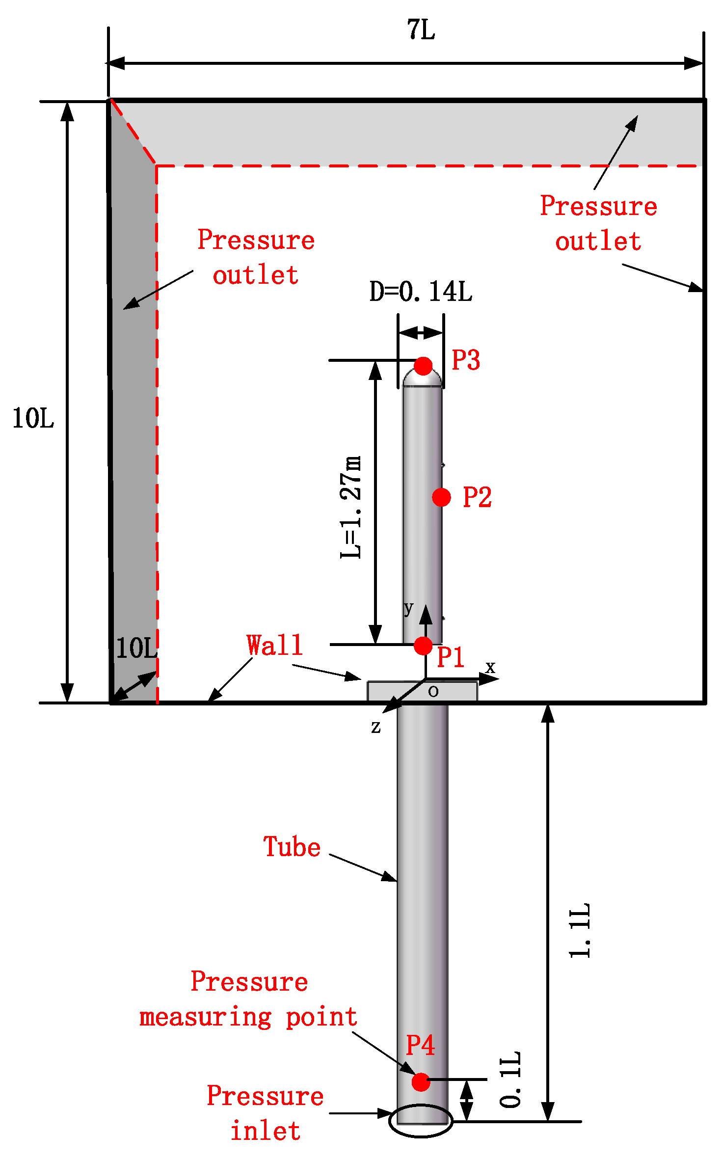
3.1. Geometrical Model and Boundary Conditions

This study mainly analyzes the ejection separation process of the surface launching platform and the missile. The model consists of a missile and a launching platform, the main feature of the launching platform is a single cylinder and single bullet structure, and the missile and the launching cylinder are constrained and separated by means of a slide guide. Due to the ejection method, a flow stopper ring is added near the mouth of the launching tube to meet the requirement of the velocity of the missile out of the tube.
The computational domain of the model contains not only the flow field region inside the launch tube but also the outer flow field region, consisting of the upper surface and the upper part of the launch platform. The computational domain is a cubic computational domain, and the computational domain and boundary conditions are shown in Figure 3. The height of the computational domain in the vertical direction is 10 L. In addition, the length of the computational domain is chosen to be 7 L, and the width of the computational domain is chosen to be 10 L. The top and side boundaries of the computational domain are the boundary conditions for the pressure outlet. The bottom of the cylinder is the pressure inlet boundary with a pressure value of 0.63 MPa. The pressure inlet boundary at the bottom of the launch cylinder changes to a no-slip wall boundary when the tail of the projectile leaves the launch cylinder.

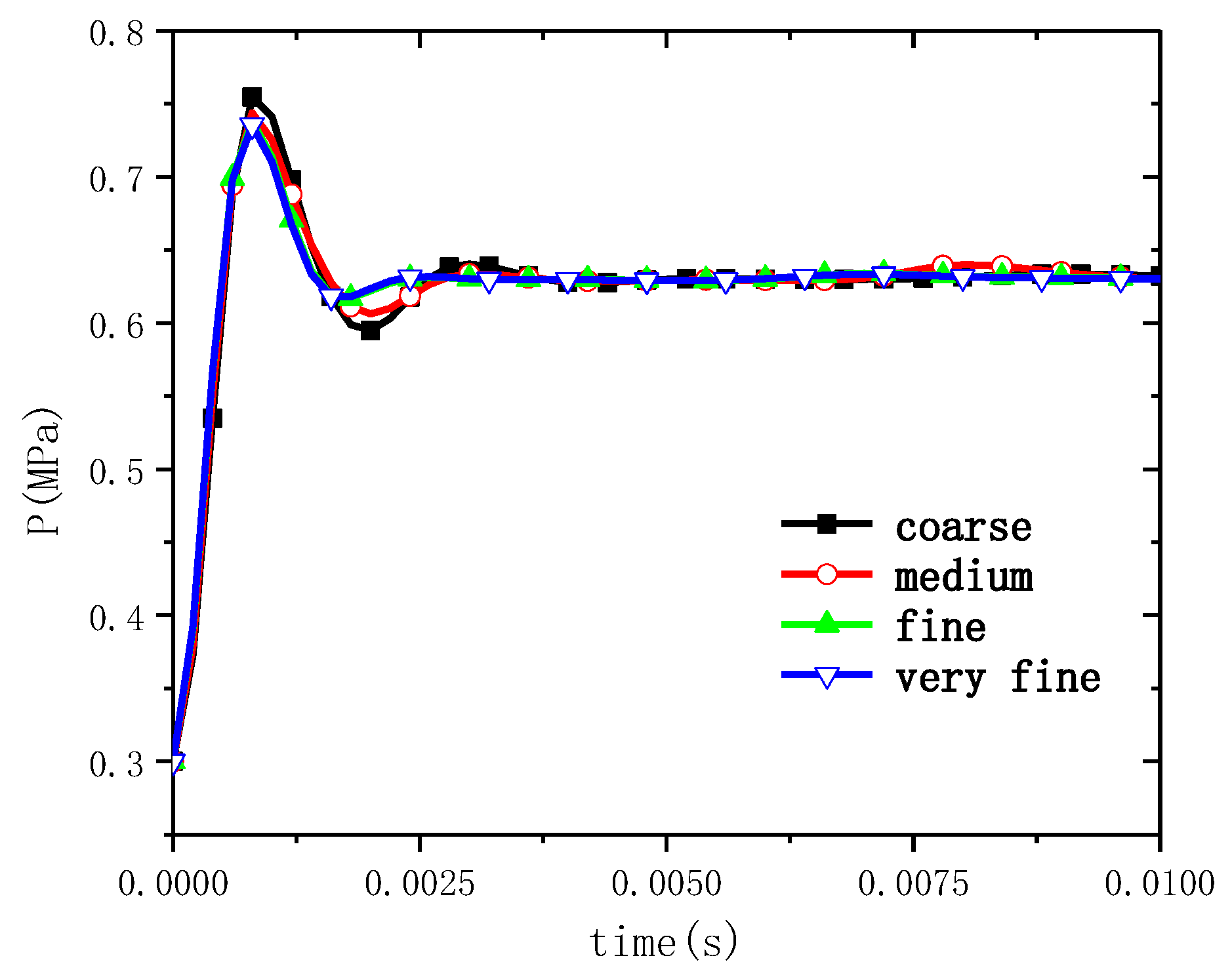
3.2. Grid Convergence Verification

The numerical model is computed using a 6DOF model based on a nested grid framework. Based on the trajectory of the missile in the computational domain, mesh refinement is performed around the trajectory until the wall resolution achieves the condition of 30 < y+ < 100. The computational domain meshing is shown in Figure 4.
The mesh-independence of the computational model mesh was verified prior to the development of the analyzes. For better convergence conditions and computational time, the time step is taken as 2 × 10⁻⁶ s. The transient calculation method was used to investigate the pressure characteristics of the gas flow through the gap between the missile and the launch tube. Calculations were carried out using the above model for four different numbers of grid models, with pressure monitoring points at the cylinder gap at the bottom of the launch tube. The location of the measurement point is point P4 in Figure 3. Figure 5 shows the time history curves of the pressure at the corresponding measurement points for different grid models under the same condition.
From the figure, it can be seen that the pressure at the measuring point shows a trend of increasing and then decreasing, and then it tends to a stable value. The results show that the variation trend of measurement points is consistent under different grid densities, but the pressure tends to stabilize with the increase of grid density. Considering the computational efficiency and accuracy, this paper adopts the “fine mesh” for calculation, and the total number of grid cells is about 3.51 million.

3.3. Validations of the Numerical Approach

To verify the reliability of the flow numerical simulation method, ground tests were conducted using a concentric cylinder launcher [27]. The experiment was conducted in 2015, when it was designed to validate the new launcher. However, the experimental data are reliable and can still be used to test the validity of numerical models to solve the flow field. The gas discharge state and load response within the launcher were analyzed. The inner cylinder had a diameter of 220 mm, and the outer cylinder measured 276 mm in diameter. The test missile had a diameter of 140 mm, weighed 85 kg, and was propelled by a rocket motor with a thrust of 2.75 kN. The engine’s throat diameter, outlet diameter, total temperature, total pressure, and specific heat ratio were 17.8 mm, 41 mm, 2200 K, 8 MPa, and 1.21, respectively. The launching device consists of an inner cylinder, an outer cylinder, a hemihead, a rail, four longerons, a top block, a bottom block, and a gas guide plate. The rail guides the initial flight of the test missile. Four longerons are welded between the inner and outer cylinders at 90° intervals to support the inner cylinder. The top and bottom blocks seal the gap between adjacent longerons to disrupt the annular flow structure for exhaust gas discharge. To compensate for the reduced annular tube size caused by these blocks, the inner cylinder is offset by 15 mm to enlarge the exhaust gas discharge gap. The gas guide plate on top of the inner cylinder, which is 40 mm higher than the outer cylinder, is used to change the direction of exhaust gases. Additionally, the gap between the test missile and the inner cylinder is sealed with a rubber block.
Two high-speed CCD cameras with a sampling rate of 2000 frames per second and a resolution of 1280 × 1024 were used to measure the launching process and flow states of exhaust gases above the head of the launching cylinder. They were positioned at the side of the launcher with a 90-degree intersection angle. During the test, the static pressure was measured at the bottom apex of the launch tube and at four measurement points on the inner and outer tube gaps. The arrangement of the high-speed camera and measurement points is shown in Figure 6a.
Combined with the test, the above flow numerical model is used to establish a ground-based concentric cylinder launch simulation model and carry out application analysis, and the model data are the same as the test parameters. The simulation model includes the concentric tube launcher, the test missile, and the engine. The computational domain covers the flow area inside the launcher and the ambient atmosphere. The pressure no-slip adiabatic wall is used in the structural wall, the pressure inlet boundary is used in the engine outlet, and the pressure outlet boundary is used in the atmospheric outfield region. The computational grid at typical moments of the computational process is shown in Figure 6b.
By calculating and analyzing the simulation model, the pressure profile is obtained, as shown in Figure 7. From the figure, it can be seen that the pressure change characteristics of the experimental measurement data and the simulation calculation data are similar. The maximum relative error between the two is less than 10%. The discrepancies may be due to the effect of numerical dissipation and other error factors in the CFD model. Considering that the measured signals in the launching experiment are dynamic data, the uncertainty errors of test pressure data are evaluated specifically by static tests, and the errors of static tests are estimated at 1.8%. In general, the numerical model established in this paper is reasonable.

4. Results and Discussion

In this paper, the study of the missile ejection process of a water surface moving platform is carried out based on class 5 sea state. The calculations are performed using a double-slider model, arranged on the upper and lower sides of the missile center of mass. In addition, the mass of the missile is 200 kg, and the mass of the launching platform is 10 t. The stiffness of the adapter is 700 kN/m, and the damping coefficient is 200 N·s/m. The ejection gas pressure is 0.6 MPa, and the temperature is 1000 K. The rolling, pitching, and heaving motion parameters of the launch platform are shown in Table 1.

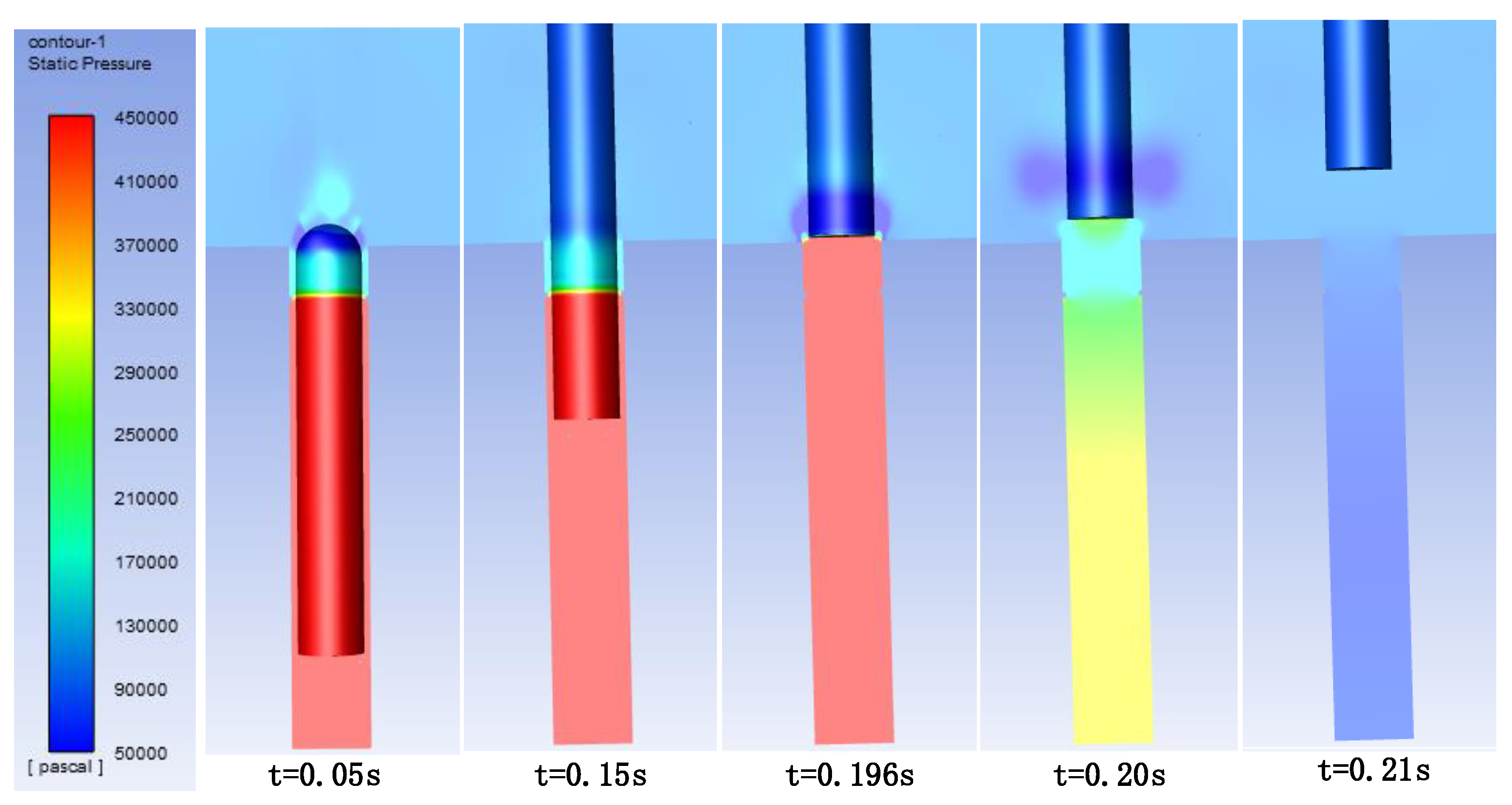
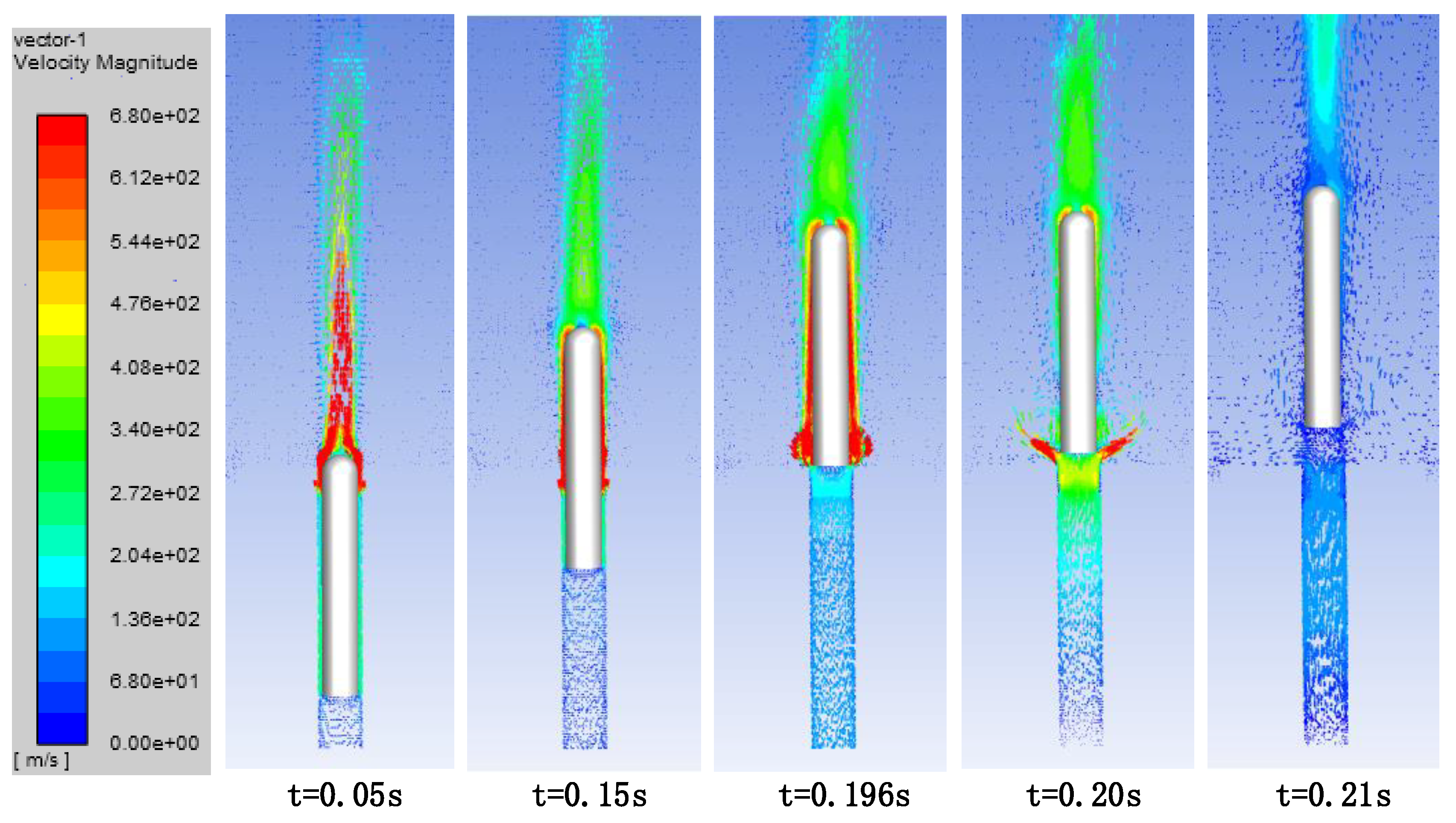
4.1. Characteristics of the Ejection Flow Field of a Moving Platform on the Water Surface

Figure 8 and Figure 9 show the pressure cloud and velocity vector diagrams of the flow field during the missile launch separation process, respectively. At t = 0.05 s, a low-pressure region appears in the missile head, which is mainly due to the effect of the flow-blocking ring. The gas in the lower part of the ring is a highly under-expanded jet, and the gas expands and accelerates after passing through the ring. After that, the expansion of the gas through the mouth of the cylinder is intensified, the speed is faster, and a low-pressure zone is formed in the head of the missile. At t = 0.15 s, the distance of the missile out of the tube increases. The gas forms an advective jet on the surface of the missile, and the pressure on the surface of the missile is low. At t = 0.196 s, the missile leaves the tube, and a ring-shaped low-pressure region appears at the missile tail. This is due to the fact that the gas is no longer constrained by the cylinder wall and the side of the missile, and the high-speed gas jet expands radially. Thereafter, the pressure inlet at the bottom of the launch tube is closed, and the ejected gas no longer increases. At t = 0.2 s, the missile exits the tube for a distance, and the gas pressure inside the tube decreases rapidly, while the fluid velocity on the missile surface also decreases rapidly. In addition, due to the friction between the gas and the wall of the missile and the fluid viscosity, a vortex region is formed at the tail of the missile. At the moment of t = 0.21 s, the pressure inside the cylinder is basically equal to the ambient pressure, and the vortex region attaches to the missile tail and moves with the missile.
The pressure time history curves of the monitoring points are given in Figure 10. P1 is the pressure measurement point at the center of the bottom of the missile. P2 and P3 are the measurement points at the middle surface of the missile and at the center of the missile head, respectively. P1 to P3 are the moving measurement points, which follow the missile movement. P4 is the measurement point at the bottom of the tube, which is fixed with respect to the launching tube. The location of the measurement points is shown in Figure 3.
From the figure, it can be seen that the pressure at the P1 and P4 measurement points is maintained at about 0.625 MPa during the movement stage in the missile tube. At t = 0.18 s, point P1 passes through the flow-blocking ring, and the pressure oscillates. This is due to the fact that after the measuring point passes through the flow-blocking ring, the measuring point is connected to the external air, and the pressure decreases briefly. However, the bottom of the cylinder continues to provide high-pressure gas, and the pressure rises again. The equilibrium pressure at point P2 is maintained at about 0.55 MPa. At t = 0.125 s, the P2 point passes through the flow barrier ring, and the pressure at the point decreases dramatically. Again, the pressure at the point decreases and remains above the ambient pressure as the bottom of the tube continues to supply the ejection gas. At t = 0.15 s, the P2 point leaves the tube, and the pressure at the point is further reduced to ambient. The P3 measurement point is not exposed to the high-pressure gas, and the pressure does not change much. However, due to the missile movement at the top of the velocity station, there is a small increase in pressure, up to 0.15 MPa. The pressure at the measurement point decreases sharply to ambient pressure after all the measurement points have moved outside the cylinder. It is noteworthy that the pressure at the P4 measurement point undergoes several cycles of oscillation before converging to the ambient pressure. This indicates that the change of gas pressure inside the cylinder is a pulsating process.

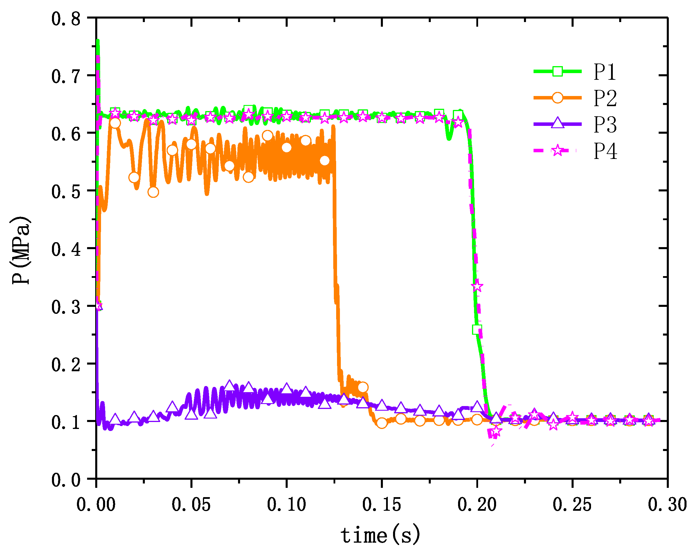
4.2. Characterisation of Object Dynamics Response

The launching platform performs rolling, pitching, and heaving motions under the action of waves. The missile is separated from the launch platform by the action of the ejection gases gas and is constrained by the launch platform throughout the separation process. Figure 11 gives the velocity and displacement curves of the motion of the missile and the launch platform along the O y direction.
It can be seen from the figure that the velocity and displacement of the missile gradually increase. At t = 0.2 s, the missile velocity reaches the maximum value of 13.6 m/s, and then the velocity remains stable. This is due to the fact that the launch platform no longer provides ejection gases after the missile leaves the tube, and the pressure at the bottom of the missile decreases rapidly at the moment of leaving the tube. Figure 11 also gives the velocity and displacement curves of the launch platform. When t < 0.185 s, the velocity and displacement of the launch platform gradually increase. This is the result of the joint action of the vertical oscillation active force, the gas force, and the friction between the guide rail and the slider in the O y direction of the launching platform. After the missile leaves the cylinder, the motion speed of the launch platform gradually decreases, and at this stage, the launch platform is only subjected to the vertical oscillation active force. Through comparison, it can be concluded that the motion velocity and displacement of the launch platform are very small compared with that of the missile, indicating that the model can effectively realize the launch separation of the missile and the platform.
Since the effect of transverse rocking on the missile is more pronounced, the motion characteristics caused by transverse rocking are mainly analyzed next. Figure 12 gives the constraint force and velocity profile of the missile in the O z direction. The force curve in the figure is the constraint force on the missile under the inertial system, which is mainly generated by the contact collision between the slider and the guideway. The velocity profile reflects the kinetic response of the projectile when subjected to external constraining forces. As shown in the figure, t = 0.025~0.05 s, the displacement of the slider in the O 1 z 1 direction of the cylinder system is larger than the gap of the guide rail slider, which generates the contact force. The velocity of the missile increases gradually after it is subjected to the constraining force. At t = 0.05~0.075 s, the missile is released from contact under the action of the constraining force, the two do not produce constraining force, and the velocity of the missile is relatively stable. Thereafter, with the growth of the distance of the missile out of the cylinder and the active motion of the launch platform around the X-axis, there exists a longer contact between the two until the lower sliding block leaves the cylinder. During this period, the missile’s velocity gradually increases under the action of the constraining force. The constraining force directly changes the missile’s velocity and thus its displacement, ensuring that the missile’s relative position is stable under the cylinder system.
Figure 13 gives the parameters of the rotation of the missile and the launch platform about the X-axis. Figure 13a gives the constraining moment to which the missile is subjected and the angular velocity profile of the rotation, where the angular velocity profile of the launch platform is given by the active motion. The constraining moment to which the missile is subjected is obtained according to Equation (13), and the action time corresponds to the constraining force to which it is subjected. As shown in the figure, the rotational angular velocity of the missile is relatively stable when no constraining moment is generated. When t < 0.125 s, the missile is subjected to a smaller restraining moment and its angular velocity changes less. Thereafter, the missile is subjected to a larger rotational moment, and the angular velocity of the missile decreases rapidly to 0.01 rad/s. When the lower slider leaves the cylinder, it no longer restrains the restraining moment, and the angular velocity of the missile remains stable. Similarly, the restraining moment directly changes the missile rotational angular velocity and thus the missile corner. Figure 13b gives the curve of the rotation angle of the missile around the X-axis. From the figure, it can be seen that the trend of the rotation angle change of the missile and the launch platform remains the same at t = 0~0.18 s. After that, the effect of the guideway slider constraint disappears and the two move independently. The above results show that the guideway slider constraint model can well characterize the constraint effect of the platform on the missile during the launching process.

4.3. Effect of Wind Load on the Ejection Process

Missile launching from the water surface of a launch platform is usually accompanied by wind loads. In this section, a numerical simulation of the missile launching process under wind load is carried out by using the model established above, which mainly analyzes the effect of wind load on the missile ejection process. The case without wind load is named as C1, the case with wind load is named as C2, and the velocity of the wind load is 10 m/s along the X-axis of the inertial system.
The velocity vector diagram of the flow field for the C2 condition is given in Figure 14. From the figure, it can be seen that the wind loading around and at the head of the missile is not significant. This may be due to the fact that the surface of the projectile is wrapped by the gas jet to form an advective jet during the movement phase in the missile tube. The jet velocity is much higher than the transverse wind velocity, so the wind load has less effect on the missile exit process from the cylinder. The velocity of the gas jet farther above the projectile is strongly influenced by the crosswind, and the velocity vector field appears asymmetric. After the missile exits the tube, the launch tube no longer provides the ejection gas, the fluid velocity on the missile surface decreases rapidly, and the effect of wind loading is obvious.
The displacement curves of the missile along the O y direction in the two working conditions are given in Figure 15. From Figure 15, it can be seen that the two curves almost completely overlap, indicating that a wind load of 10 m/s has no effect on the axial motion of the projectile.
The force and displacement curves of the missile along the O x direction are given in Figure 16. From Figure 16a, it can be seen that the two curves have a certain similarity, and the oscillation peaks of the C2 case are larger than those of the C1 case due to the wind load. However, the number of oscillations and the action time of the C1 case are higher than those of the C2 case, resulting in almost no difference in the displacement along the O x direction in Figure 16b for the missile during the movement stage in the cylinder. After the missile is out of the cylinder, the effect of wind load on the missile becomes larger, and its displacement along the negative O x direction becomes slower.
Figure 17 gives the restraining moment received by the missile as well as the turning angle curves. From Figure 17b, it can be seen that the two curves are almost identical at t < 0.05 s. This is because neither of them receives a constraining moment at that moment. At t = 0.05~0.18 s, the difference between the two curves increases and then decreases and reaches the maximum value at the same moment, which is due to the different size and time of the restraining moment. At t > 0.18 s, the missile is no longer subjected to the restraining moment, and its rotational angle around the Z-axis under the action of the wind load decreases rapidly.

5. Conclusions

In this paper, a RNG k-ε turbulence model, energy equations, NS equations, and an overlapping grid technique are used. The surface ejection separation process of the missile under the multi-field coupling effects of the guide slide, the ejection gas, and the waves are simulated. The focus is on the pressure and velocity field characteristics of the ejection process, as well as the motion law of the missile and the launch platform. In addition, the effect of a 10 m/s wind load on the missile ejection process is also investigated. The specific conclusions are as follows:
(1)
A coupled computational model for surface dynamic platform launches incorporating flow and motion constraints was developed. Numerical simulations were carried out for the experimental ground conditions of the concentric tube launcher. The numerical calculation results are in good agreement with the results of the conducted experiments, indicating that the numerical model and parameters used were appropriate.
(2)
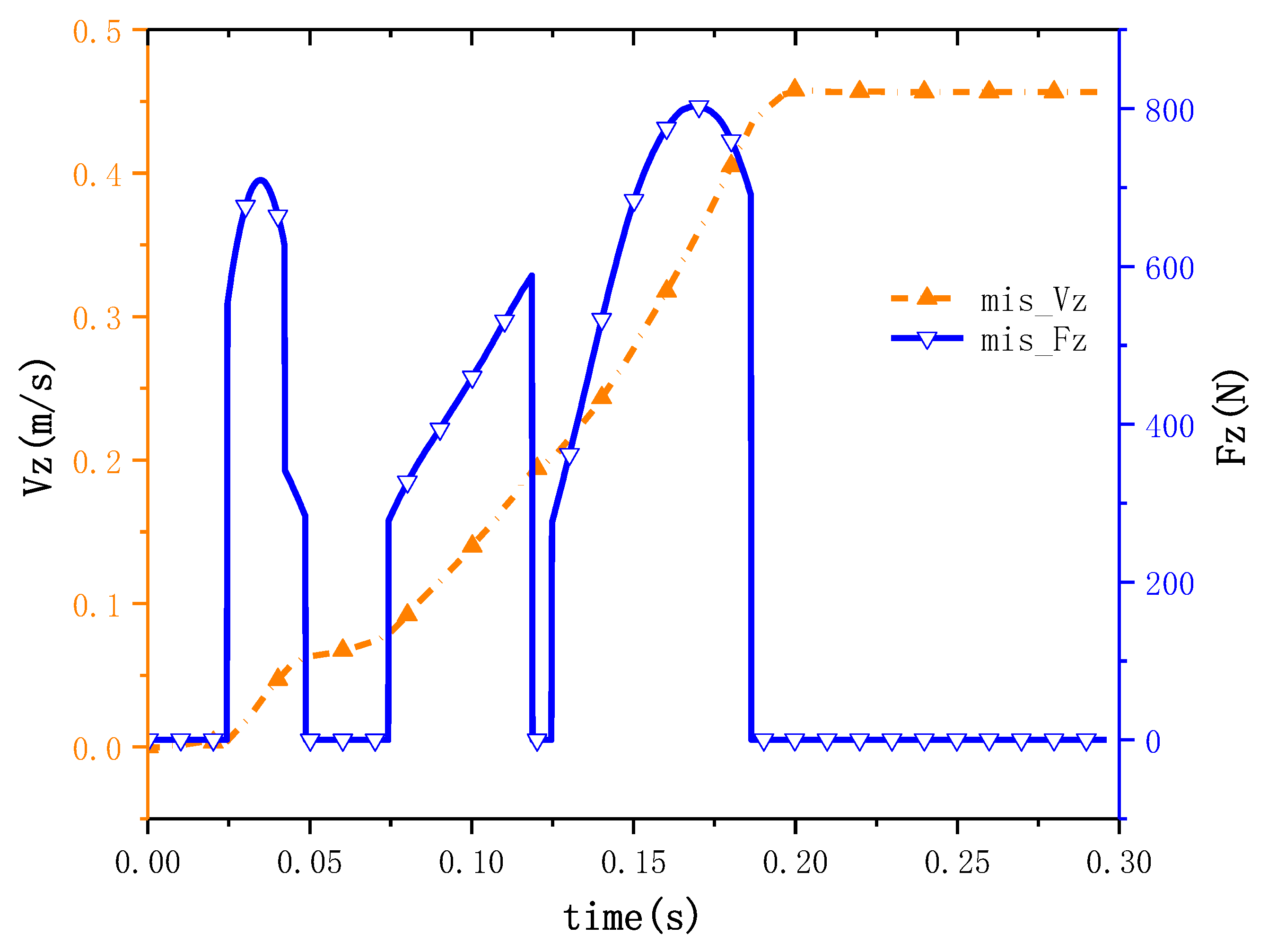
The coupled model can effectively simulate the launch separation process of the projectile under the constrained state. The numerical simulation results of the missile launching process under specific sea state show that the motion characteristics of the missile and the launching platform are in good agreement in the constrained direction.. The constraint model can also provide a reference for the study of the missile launching process of unmanned underwater vehicles (UUVs) and the separation of aircraft and projectiles under aircraft constraints.
(3)
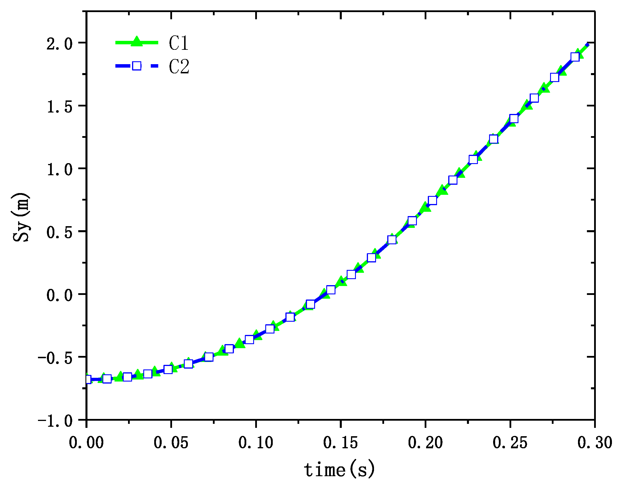
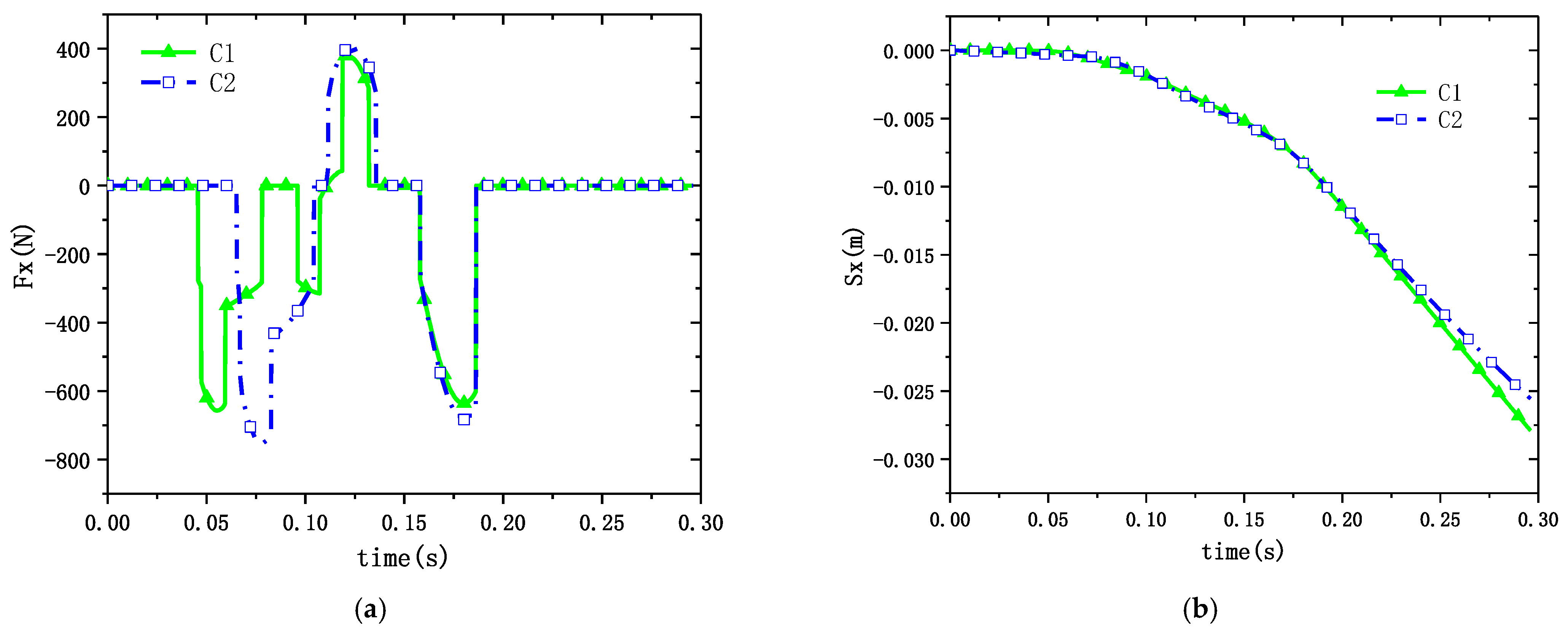
A 10 m/s wind load has a small effect on the movement phase of the missile tube. Under a 10 m/s fixed wind speed state, the ballistic pattern of the missile tube has very little change from the 0 wind speed state, and after the missile is out of the cylinder, it is more affected by the wind load.

Author Contributions

Conceptualization, H.L. and D.F.; methodology, D.F. and H.L.; software, S.L. and S.H.; validation, H.L. and S.L.; formal analysis, H.L. and D.F.; investigation, H.L.; resources, D.F. and S.L.; data curation, S.L. and H.L.; writing—original draft preparation, H.L.; writing—review and editing: S.L. and D.F.; supervision, D.F.; project administration, D.F.; funding acquisition, D.F. All authors have read and agreed to the published version of the manuscript.

Funding

The authors appreciate the support from the National Natural Science Foundation of China (Grant No. U23B6009).

Institutional Review Board Statement

Not applicable.

Informed Consent Statement

Not applicable.

Data Availability Statement

The data presented in this study are available upon request.

Conflicts of Interest

The authors declare no conflicts of interest.

References

  1. Liu, C.L.; Zhang, Y.W.; Wang, Y.D.; Qi, X.B. Investigation into Load Characteristics of Submarine-launched Missile Being Ejected from Launch Tube Considering theAdapter Elasticity. Acta Armamentarii 2015, 36, 379. [Google Scholar] [CrossRef]
  2. Li, W.; Zhang, Z.; Lu, J.; Li, Z.; Wang, C. Investigations on the flow characteristics and the structural response of the launch tube during the underwater launching process. Ocean Eng. 2023, 279, 114603. [Google Scholar] [CrossRef]
  3. Guo, C.; Zhang, B.; Guo, H.; Cui, S.; Zhu, B. Vehicle-bridge dynamic response analysis under copula-coupled wind and wave actions. Ocean Eng. 2023, 285, 115444. [Google Scholar] [CrossRef]
  4. Purdon, M.; Hetreed, C.; Hudson, M. F-35 pre-flight store separation analyses: Innovative techniques for affordability. In Proceedings of the 47th AIAA Aerospace Sciences Meeting Including the New Horizons Forum and Aerospace Exposition, Orlando, FL, USA, 5–8 January 2009. [Google Scholar] [CrossRef]
  5. Zhao, H.; Wang, M.J.; Yang, W.; Li, Y.Q.; Zhao, S.P. Adapters for canister-launched missile. Tactica Missile Technol. 2007, 4, 42–50. [Google Scholar] [CrossRef]
  6. Baker, P. AUV launch and recovery-a key enabling technology for organic MCM operations. In Proceedings of the Pacific 2013 International Maritime Conference: The Commercial Maritime and Naval Defence Showcase for the Asia Pacific, Barton, Australia, 1 January 2013. [Google Scholar] [CrossRef]
  7. Choi, S.; Kim, C.; Rho, O.H.; Park, J.J. Numerical analysis on separation dynamics of strap-on boosters in the atmosphere. J. Spacecr. Rocket. 2002, 39, 439–446. [Google Scholar] [CrossRef]
  8. Rao, B.N.; Jeyakumar, D.; Biswas, K.K.; Swaminathan, S.; Janardhana, E. Rigid body separation dynamics for space launch vehicles. Aeronaut. J. 2006, 110, 289–302. [Google Scholar] [CrossRef]
  9. Singaravelu, J.; Jeyakumar, D.; Rao, B.N. Taguchi’s approach for reliability and safety assessments in the stage separation process of a multistage launch vehicle. Reliab. Eng. Syst. Saf. 2009, 94, 1526–1541. [Google Scholar] [CrossRef]
  10. Jafari, M.; Parhizkar, H.; Ghasemlu, S. Simulation of strap-on boosters separation in the atmosphere. Int. J. Eng. 2015, 28, 164–171. [Google Scholar] [CrossRef]
  11. Olejnik, A.; Dziubiński, A.; Kiszkowiak, Ł. Separation safety analysis using CFD simulation and remeshing. Aerosp. Sci. Technol. 2020, 106, 106190. [Google Scholar] [CrossRef]
  12. Tian, S.; Fu, J.; Chen, J. A numerical method for multi-body separation with collisions. Aerosp. Sci. Technol. 2021, 109, 106426. [Google Scholar] [CrossRef]
  13. Pan, X.; Jiang, Y.; Hu, D.; Guan, H. Influence of external factors on airborne missile’s horizontal backward launching. Int. J. Aerosp. Eng. 2021, 2021, 1081252. [Google Scholar] [CrossRef]
  14. Tian, S.; Li, R.; Xu, K. Investigation of Aeroelasticity Effect on Missile Separation from the Internal Bay. Int. J. Aerosp. Eng. 2023, 2023, 9875622. [Google Scholar] [CrossRef]
  15. Wei, X.; Li, D.; Wang, C.; Liu, X. Structure dynamics analysis of multistage submarine missile shell. In Proceedings of the 2011 International Conference on Electronic & Mechanical Engineering and Information Technology, Harbin, China, 12–14 August 2011. [Google Scholar] [CrossRef]
  16. Liu, H.; Wang, X. Simulation and Analysis on the Dynamic of a Missile Launch Canister. In Proceedings of the 2020 5th International Conference on Mechanical, Control and Computer Engineering (ICMCCE), Harbin, China, 25–27 December 2020. [Google Scholar] [CrossRef]
  17. Shang, S.C.; Sun, J.Z. Research on the Affection of the Underwater Missile Launching Process. Appl. Mech. Mater. 2012, 130, 2594–2599. [Google Scholar] [CrossRef]
  18. Liu, H.; Li, S.; Fu, D.; Bi, F. Underwater ejection multifield coupling model and response characteristics. Ocean Eng. 2023, 274, 114021. [Google Scholar] [CrossRef]
  19. Zeng, P.; Jiang, Y.; Yang, L. Interior Ballistics of Independent Water-surface Launching Canister. Acta Armamentarii 2022, 43, 1266. [Google Scholar] [CrossRef]
  20. Wang, X. Separating Kinematic Characteristics of Submarine Launched Missile near the Free Surface. J. Astronaut. 2021, 42, 496. [Google Scholar] [CrossRef]
  21. Liu, B.; Cheng, D.; Lu, B.; Chen, X.; Le, G. Modeling and Simulation of Transmedia Separation of Missile Ejected from Carrier with Adapter. Acta Armamentarii 2023, 44, 1237. [Google Scholar] [CrossRef]
  22. Li, X.; Chen, X.Q.; Meng, L.T. Analysis on the Effect of Ship swaying Motion on ship-borne vertically launch missile in launching process. Missiles Space Veh. 2014, 5, 19–21. [Google Scholar]
  23. Liang, X.Y.; Su, Y.F.; Le, G.G. Numerical analysis of hot launch of missile from a launch canister. J. Aerosp. Power 2022, 37, 1643–1653. [Google Scholar] [CrossRef]
  24. Lee, B.S.; Choi, J.H.; Kwon, O.J. Numerical simulation of free-flight rockets air-launched from a helicopter. J. Aircr. 2011, 48, 1766–1775. [Google Scholar] [CrossRef]
  25. Borynyak, K.I.; Hrebtov, M.Y. Large eddy simulation of turbulent diffusion in swirling jets. Heat and Mass Transfer and Hydrodynamics in Swirling Flows (HMTHSF-2019). In Proceedings of the Seventh International Conference, Rybinsk, Russia, 16–18 October 2019. [Google Scholar] [CrossRef]
  26. Sahebjam, R.; Kohan, K.F.; Gaskin, S. The dynamics of an axisymmetric turbulent jet in ambient turbulence interpreted from the passive scalar field statistics. Phys. Fluids 2022, 34, 015129. [Google Scholar] [CrossRef]
  27. Fu, D.; Hao, H. Investigations for missile launching in an improved concentric canister launcher. J. Spacecr. Rocket. 2015, 52, 1510–1515. [Google Scholar] [CrossRef]
Figure 1. Schematic representation of the force state.
Jmse 12 01736 g001
Figure 2. Motion and flow coupling calculation process.
Jmse 12 01736 g002
Figure 3. Computational domain and boundary conditions.
Jmse 12 01736 g003
Figure 4. Computational domain meshing.
Jmse 12 01736 g004
Figure 5. Pressure curves at measurement points.
Jmse 12 01736 g005
Figure 6. Schematic diagram of the test setup and launch process grid: (a) schematic diagram of the test setup; (b) schematic of the launch process grid.
Jmse 12 01736 g006
Figure 7. Comparison of data and experimental procedure.
Jmse 12 01736 g007
Figure 8. Flow field pressure cloud.
Jmse 12 01736 g008
Figure 9. Vector diagram of flow field velocity under no crosswind conditions.
Jmse 12 01736 g009
Figure 10. Time-calendar curve of pressure at monitoring points.
Jmse 12 01736 g010
Figure 11. Motion parameter curve of the object along the Y-direction: (a) displacement and velocity curves for cylinder and projectile; (b) enlarged displacement and velocity curve of the cylinder.
Jmse 12 01736 g011
Figure 12. Binding force and velocity profile of the missile in Z-direction.
Jmse 12 01736 g012
Figure 13. Parameter curve of object rotation around X-axis: (a) constraining moment and rotational angular velocity of the missile; (b) angle of rotation of the object about the X-axis.
Jmse 12 01736 g013
Figure 14. Vector plot of velocity of flow field under 10m/s crosswind condition.
Jmse 12 01736 g014
Figure 15. Displacement curve of the missile along the Y-direction.
Jmse 12 01736 g015
Figure 16. Force and displacement of the missile along the X-direction: (a) missile force curve in the X-direction; (b) missile displacement curve in the X-direction.
Jmse 12 01736 g016
Figure 17. Moment versus angle of rotation curve for missiles: (a) constraining moment on missiles; (b) displacement curve of the missile around the Z-axis.
Jmse 12 01736 g017
Table 1. Motion parameters of the launch platform in typical sea states.
Level 5 Sea StateRollingPitchingHeaving
Amplitude12°2.5°1.9 m
Period [s]1066
Disclaimer/Publisher’s Note: The statements, opinions and data contained in all publications are solely those of the individual author(s) and contributor(s) and not of MDPI and/or the editor(s). MDPI and/or the editor(s) disclaim responsibility for any injury to people or property resulting from any ideas, methods, instructions or products referred to in the content.

