Article

Offshore Experimental Work of a Pump Directly Driven by a Fully Passive Dual-Flapping-Foil Hydrokinetic Turbine

1
Korea Institute of Ocean Science and Technology, Busan Metropolitan City 49111, Republic of Korea
2
PIELDS Engineering Co., Ltd., 186 Gasan Digital 1-ro, Seoul 08502, Republic of Korea
3
Department of Mechanical System Engineering, Jeju National University, 102 Jejudaehak-ro, Jeju 63243, Republic of Korea
*
Author to whom correspondence should be addressed.
J. Mar. Sci. Eng. 2024, 12(10), 1747; https://doi.org/10.3390/jmse12101747
Submission received: 4 September 2024 / Revised: 16 September 2024 / Accepted: 18 September 2024 / Published: 3 October 2024
(This article belongs to the Section Ocean Engineering)

Abstract

:
In this study, a previously developed fully passive hydrokinetic turbine with two flapping foils was used to directly drive a reciprocating pump, and the performance of this system was investigated at an offshore site in Republic of Korea. The fully passive operation of the turbine worked effectively due to its coupling mechanism, and pumping was successfully carried out during flood tides when the pumping height was consistently maintained using a water level gauge and winch system. Pumping occurred at a height of approximately 9 m when the flow velocity reached 1.8 m/s, at which point the corresponding Reynolds number exceeded one million. In one case where a high pumping flow rate was achieved during offshore trials conducted over a period of time, the pumping efficiency reached up to 34% when the reduced frequency of the turbine was 0.126, falling within the known optimum range. The pump driven by the flapping-foil hydrokinetic turbine, which can be positioned near the shore or in shallow water, could provide a viable solution for off-grid communities needing to pump seawater or generate hydroelectric power.

1. Introduction

The climate change crisis has heightened the importance of renewable energy as an alternative to fossil fuels [1,2]. Hydrokinetic turbines, which extract energy from water currents as a type of renewable resource, offer the advantage of being environmentally friendly without requiring the construction of dams. These turbines come in various types, such as horizontal-axis turbines (HATs), vertical-axis turbines (VATs), and flapping-foil turbines (FHTs), which are inspired by the movements of aquatic animals [3]. Flapping-foil turbines were originally developed for wind energy by McKinney et al. and, as described above, generate electricity through the flapping motion of foils, similar to the flapping of bird wings [4]. Unlike the more widely used horizontal-axis turbines, flapping-foil turbines have the advantages of lower foil speeds and the ability to operate in shallow waters [3]. For these reasons, many studies have explored the application of this technology to river and tidal current power generation [5].
When calculating the power efficiency of an FHT with a semi-passive activation mechanism, as introduced earlier, the power used for the pitching motion is subtracted from the extracted power. Therefore, many recent studies have focused on fully passive mechanisms to enhance competitiveness with HATs. The fully passive activation of a turbine with a single foil using pitch and heave springs has been demonstrated through experimental work [6]. It was reported from the experimental investigation of a similar single system that fully passive activation could be achieved without any pitching stiffness for a pitching axis located between 31% and 39% of the chord length [7]. For dual configurations, Kinsey et al. designed and experimentally verified a fully passive prototype using a crank–rocker linkage with hydrofoils in a pitch–heave motion arranged in a seesaw pattern [8]. A similar dual system with an identical phase difference of 180 degrees demonstrated the same self-starting performance [9]. An experimental study of a full-passive dual hydrokinetic turbine using a crank–slider linkage was conducted to find out the beneficial vortex interaction mode for power extraction [10]. The concept of a dual configuration using a hydraulic system with coupled hydrofoils and a phase difference of 90 degrees was proposed and simulated to analyze wake interaction effects [11]. An actual turbine system with a dual configuration and a phase difference of 90 degrees was recently developed and verified in an indoor experiment [12]. Interestingly, a recent experimental study reported that two fully passive single foil systems achieved an efficiency greater than twice that of a single foil’s efficiency [13].
Wind pumps, a long-standing method of renewable energy generation, have been employed to pump water in what is now Afghanistan, Iran, and Pakistan since at least the 9th century [14]. Pumps powered by renewable energy resources such as solar and wind are particularly useful in remote locations where a steady fuel supply is difficult to maintain, and skilled maintenance personnel are scarce [15]. Another example of a pump powered by renewable energy resources is the hydro-powered water pump, which has been in use since the 18th century; among these, hydrokinetic turbines have been used for water pumping from the 20th century to the present [16]. In a recent study [17], a hydrokinetic device using river currents, consisting of a tubular turbine directly driving a centrifugal pump, was designed and developed based on computational fluid dynamics (CFD) and model testing. The practical application of a tidal current-based pump was demonstrated with a rotary hydrokinetic turbine installed in a coastal area of Alaska, USA [18]. A Garman turbine, another type of hydrokinetic turbine, was also developed in the Sudan for water pumping along the Nile [19]. However, a pump driven by a flapping-foil hydrokinetic turbine has not yet been reported.
In this study, a reciprocating pump based on a flapping-foil hydrokinetic turbine, which differs from centrifugal pumps, was designed, fabricated, and tested at an offshore site in South Korea.

2. Methods and Materials

2.1. Pump System Using Dual-Flapping-Foil Hydrokinetic Turbine

Figure 1(Top) illustrates the dual-flapping-foil hydrokinetic turbine (DFHT), including its coupling mechanisms, where only the vertically arranged hydrofoils are immersed in water. Each hydrofoil axis rotates on its corresponding arm. The shaft of each arm is connected to the reciprocating bar via a bevel gear located on the top plate, and the reciprocating rod of the cylinder then pumps water from the inlet pipe to the outlet pipe, as shown in the zoomed image. In the turbine, the first-level chain linkage in the coupling mechanism, which enables fully passive operation, runs from the sprocket mounted on the rear arm axis to the double sprocket that rotates freely at the front arm axis. The second-level chain linkage runs from the double sprocket to the sprocket attached to the front hydrofoil pitching axis, and vice versa [11]. As depicted in Figure 1(bottom), the flapping motion of one side is coupled with the pitch motion of the other side and vice versa in one cycle. The gear ratio of the sprockets is fixed at 2:1, which determines the ratio of the pitch angle to the flapping arm angle.
As listed in Table 1, the length of the flapping arm is 2.83 times the chord length and the span is 3.67 times the chord length to achieve the target swept area. The flapping and pitch angles are set at 30 degrees and 60 degrees, respectively, based on the given gear ratio. Although the pitch angle is slightly smaller than the optimal range for power extraction reported in previous work [20], it still falls within the effective range for power extraction. A phase difference of 90 degrees between the pitch angle and the flapping angle is commonly used, and a phase difference of 90 degrees between the front and rear foils is chosen to enable fully passive activation through the coupling mechanism. The chosen separation distance is 6.5c, which was also used in the separation distance for the indoor experiment in a previous study [11].

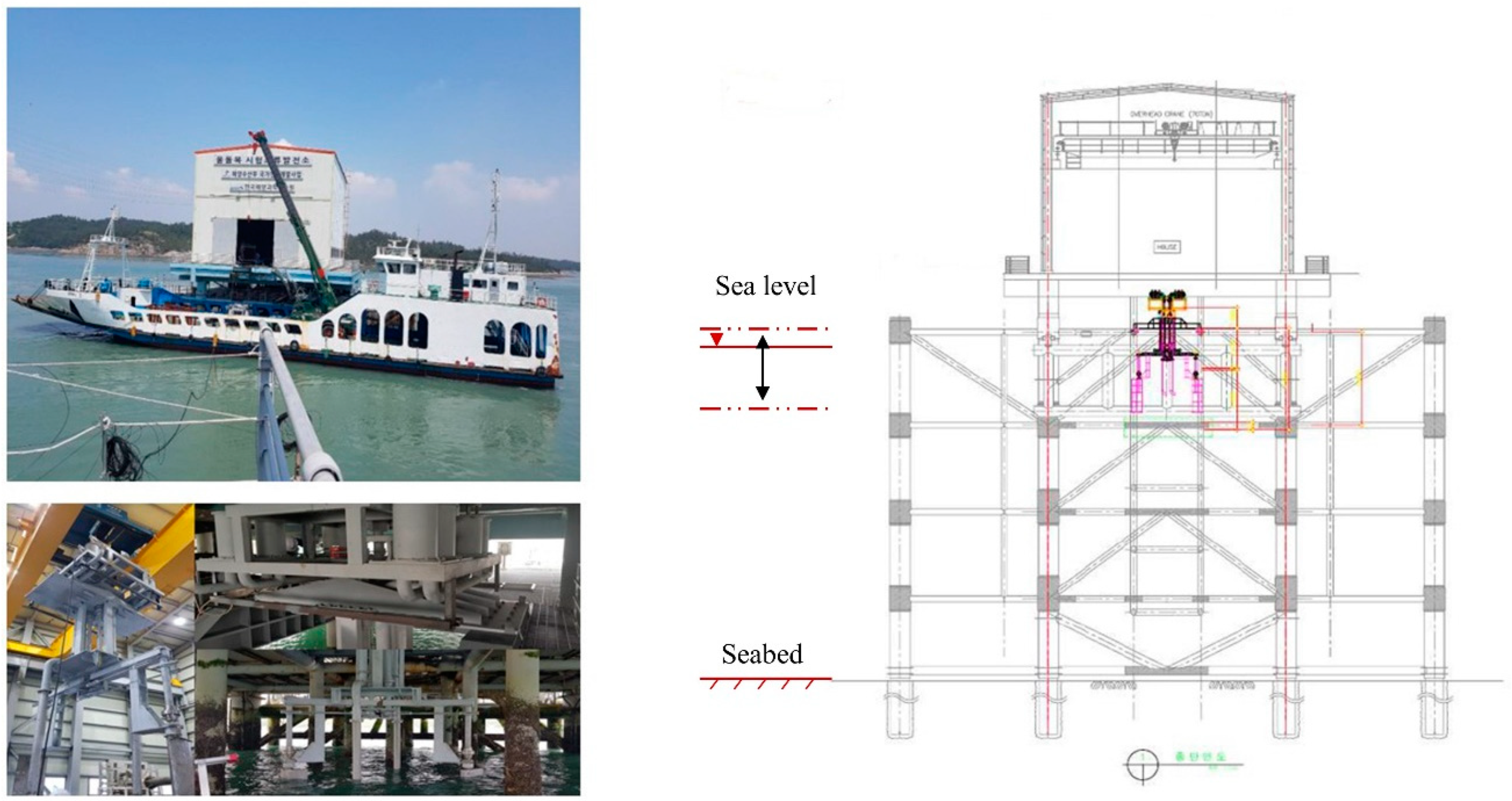
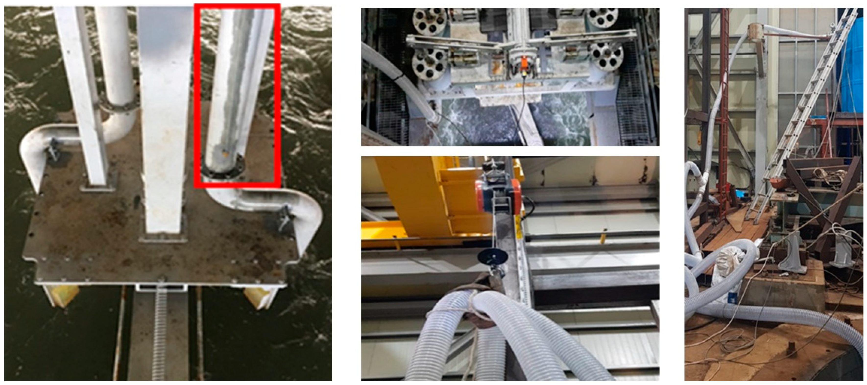
2.2. Offshore Experimental Set-Up

The conceptual drawing and prototype of the experimental apparatus are shown in Figure 2. In this apparatus, a hydrokinetic turbine-based water pumping system consists of a tidal stream turbine and a pump, as shown in Figure 2. The system includes (1) a tidal power driver that converts tidal stream energy into mechanical energy, and (2) a water pump that uses the converted mechanical energy to pump seawater. A pipeline transports the seawater to a tank located inside the jacket housing, which is located near the shore. Stainless steel was used for the submerged parts to prevent corrosion from salt.
After the design and manufacture of the tidal pump were completed, it was transported to the Uldolmok Test Tidal Power Plant in Jindo, South Korea, as shown in Figure 3. To ensure the safe installation of the unit, a new rectangular hole structure was constructed in the jacket, as depicted in Figure 2, and a crane was used to lower the pump into the designated hole. However, the flow rate uniformity was suboptimal due to the pump’s position inside the jacket, and so the experiment primarily focused on evaluating the instantaneous performance of the pump.
An operational test of the tidal pump was conducted on land before performing a real seawater demonstration test. Sea trials were then carried out to verify the pump’s functionality. The model shown in Figure 1 includes eight pumps, and the pumping load can be adjusted based on the number of connections, as indicated in Table 2.
For the sea trials, an integrated information system, shown in Figure 4, was configured to receive all data in a coordinated manner. The completed system has the following main features: real-time measurement and the storage of flow velocity and direction data (Signature series, Nortek Inc., Oslo, Norway), the real-time monitoring of the flapping motion in conjunction with the arm angle measurement system, the real-time measurement and storage of the tidal pump water volume using a digital flowmeter (LDG0100SM, Flow Digital Inc., Suzhou, China), and the real-time storage and display of statistical information, such as flow velocity and tidal power turbine data, according to the defined storage format. Additionally, information on the brakes and their controllers is provided to ensure the safe operation of the pumping system. UTCk (Coordinated Universal Time in Korea, provided by Korea Research Institute of Standards and Science, Daejeon, Republic of Korea) is an internet-based time synchronization program that synchronizes all data by coordinated universal time.

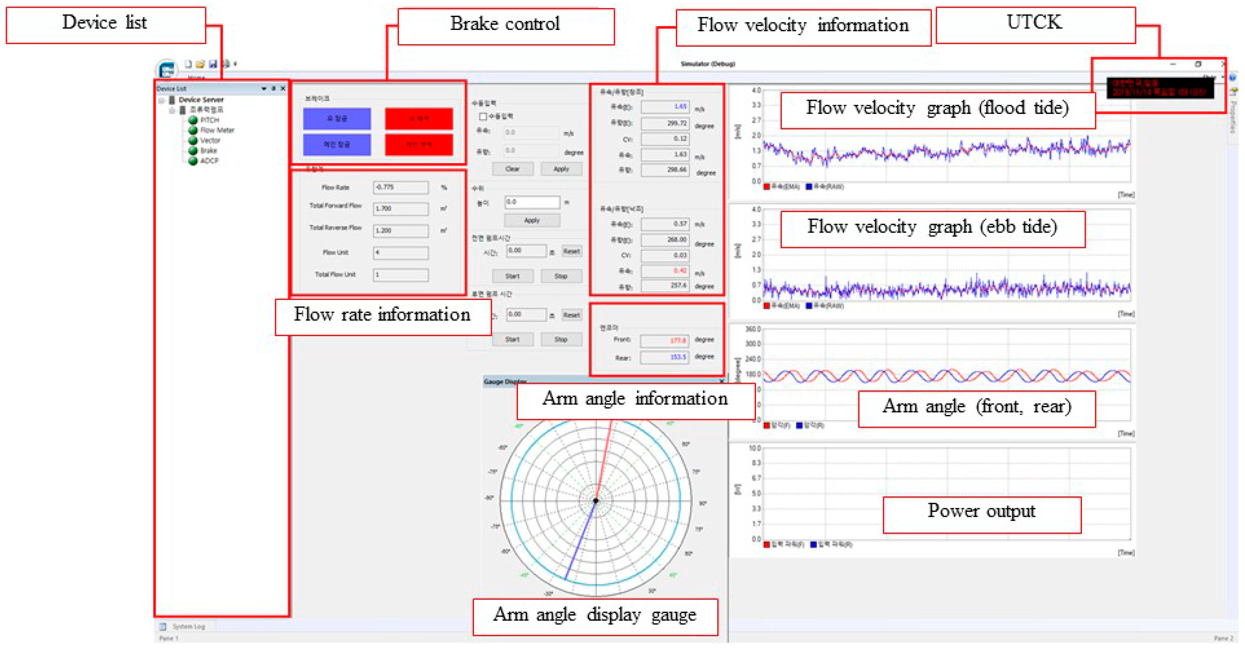
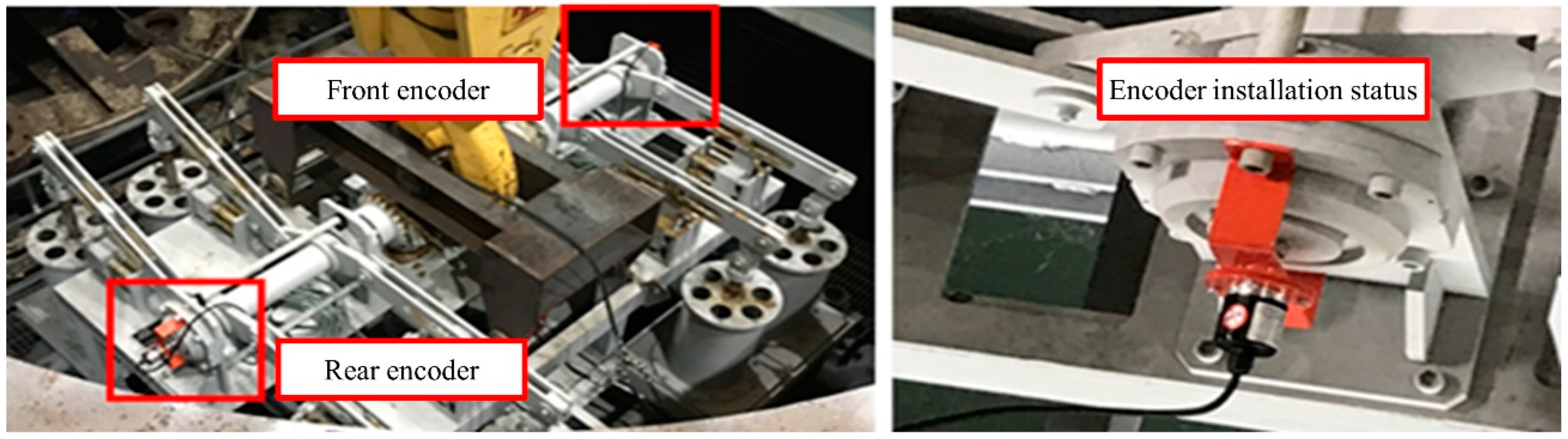
2.2.1. Measurement of Arm Angle

To measure the absolute encoder (EP50S, Autonics Inc., Busan, Republic of Korea) signal, an encoder cable (approximately 15 m long, with two sets for the front and rear) and an encoder mounting structure were assembled, as shown in Figure 5. Before installing the encoder in the tidal pump, an operational verification test was conducted on land. After installation, a further verification test was carried out to confirm that the encoder signal was correctly measured using the integrated information system.

2.2.2. Pumping Pipe and Tank

A pipeline was installed between the tidal pump and the tank, as shown in Figure 6. A solid pipe from the pump is connected to a flexible pipe which runs through the rectangular hole structure into the jacket housing. An automatic winch on the overhead crane, shown in the middle bottom picture, was used to maintain a constant pumping height (h) in response to sea level variations by reading the gauge in the left picture. The flexible pipe is then connected to the tank in the right picture after the level adjustment point controlled by the winch.

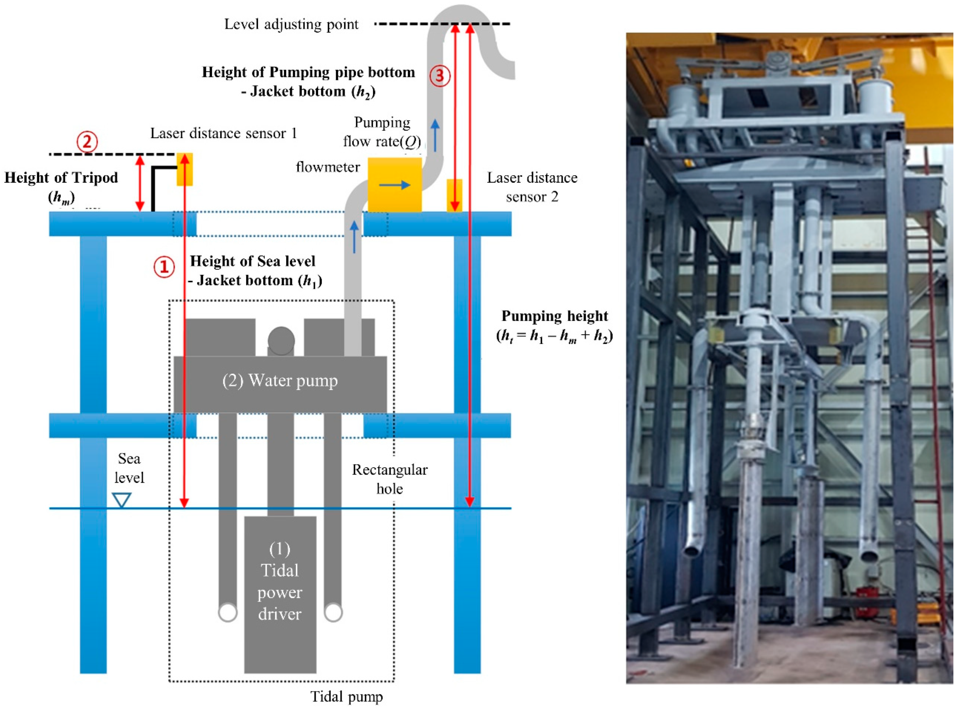
2.2.3. Flow Rate and Height Measurement

The flowmeter is connected to the integrated information system via Modbus RS-485 communication to send and receive data. Machine height and sea level/jacket bottom height were measured using a laser distance sensor (406E, Fluke Inc., Everett, WA, USA) mounted on a tripod, as shown in Figure 7. A flowmeter performance test was conducted on land by installing the flowmeter on top of the jacket deck and passing fluid through it. The heights (h1, h2, h3) were measured using the laser distance sensor, and the pumping height was calculated using the equation shown in Figure 2 with these measured values. The height information is not directly connected to the integrated information system. Instead, the average values recorded at the same time by the internet time synchronization program are manually synchronized later.

2.2.4. Pumping Power

After completing the individual operational tests of the instruments, aligning the hydrofoils and adjusting the arm angles, a behavior verification test of the tidal power driver was conducted. This behavior test was performed under relatively high-velocity conditions at the test site, with continuous monitoring of flow velocity and sea conditions. The measured positive water height and instantaneous flow rate were used to calculate the positive power output, as shown in the following equation.
P p = ρ × g × h × Q v / 60
where Pp is the pumping power [W], ρ is the density of fluid [kg/m3], g is the gravity acceleration [m/s2], h is the height [m], and Q v is the flow rate [m3/min]. The density of seawater is assumed to be constant at 1024 kg/m3, and the standard gravitational acceleration is 9.81 m/s2, based on ITTC (International Towing Tank Conference) procedure data.

3. Results & Discussion

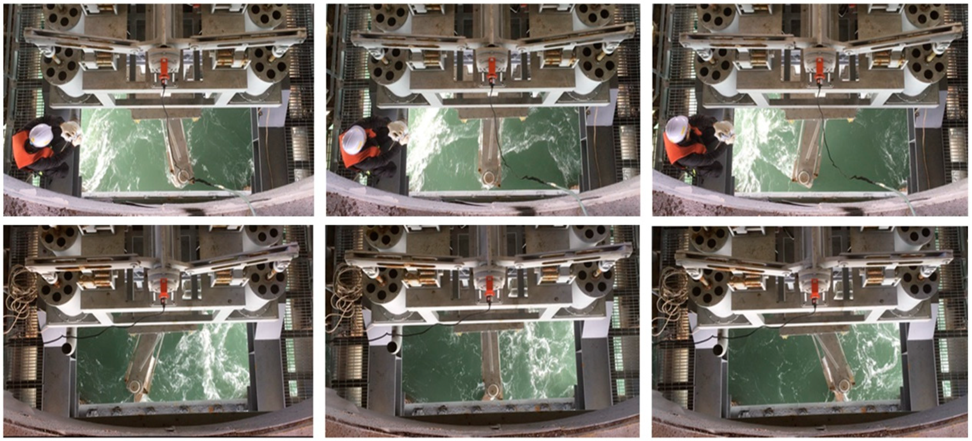
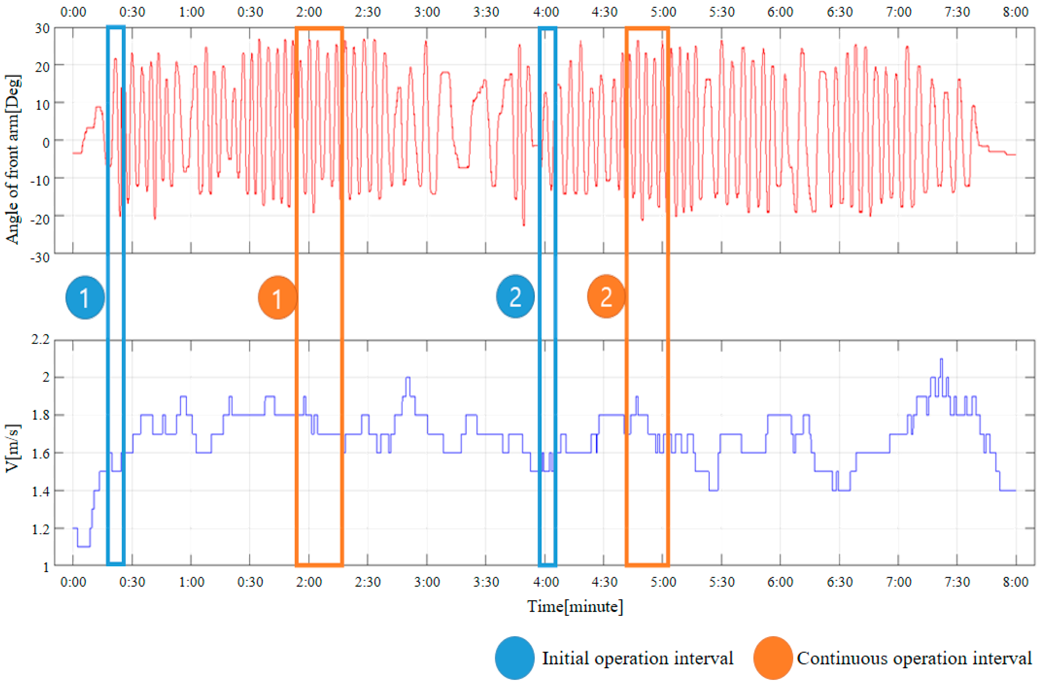
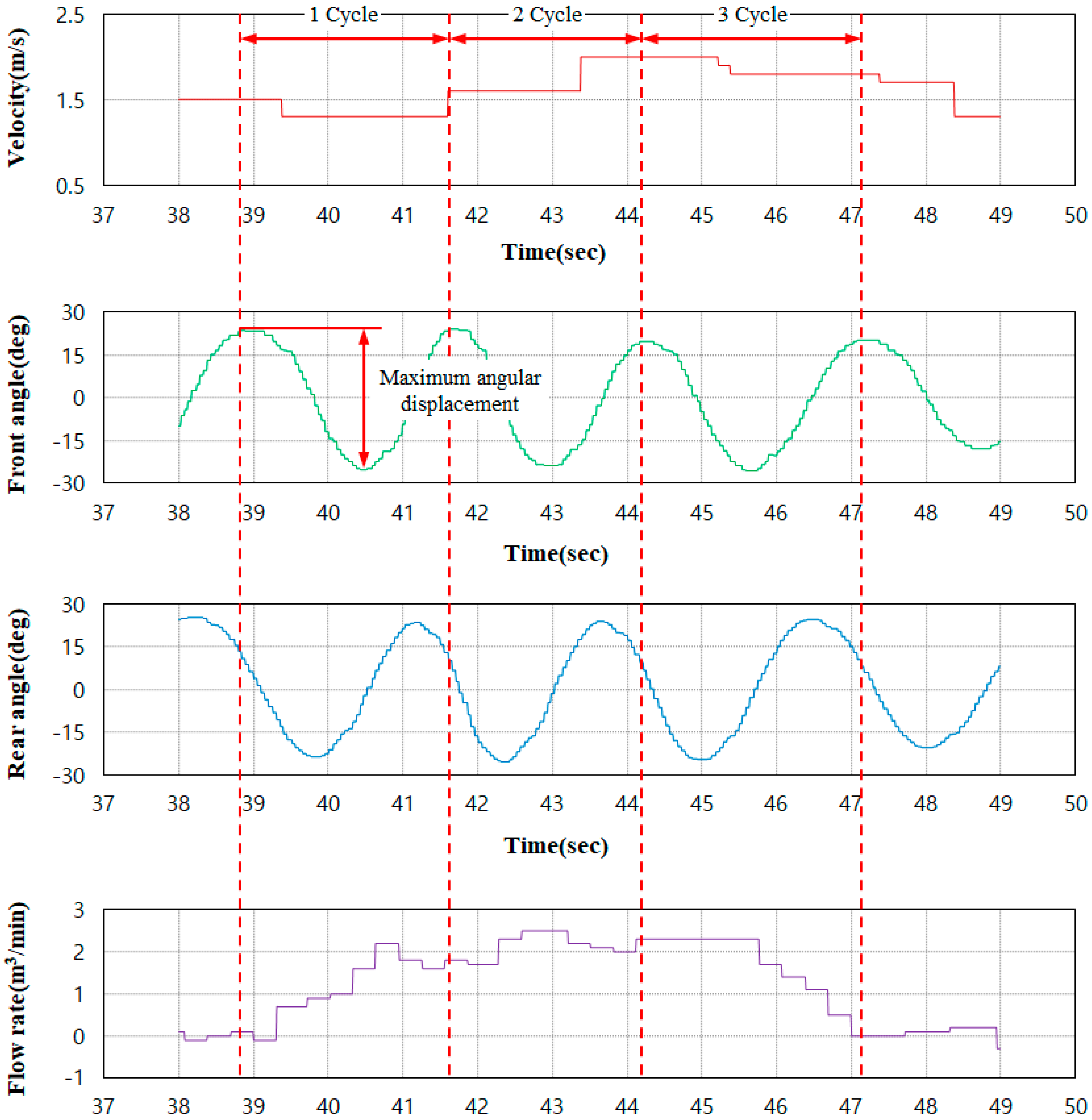
3.1. Fully Passive Activation of Arm Motion and Pumping

A fully passive arm motion of the flapping-foil hydrokinetic turbine was successfully activated on-site under high-velocity conditions, and a series of images illustrating the behavior during one cycle is shown in Figure 8. The pump lift from the foil motion was monitored using the flowmeter installed on the lower intake pipe of the tidal pump prior to testing the pump performance.
In Figure 9, the upper part shows the encoder data for the front arm used to determine the initial and continuous operation intervals, while the lower graph shows the corresponding flow velocity when data were collected in a particular case during the offshore experiments. In the graph, two distinct operation intervals were observed over eight minutes: the initial operation intervals occurred during the increase in flow velocity, while the continuous operation intervals were noted when the average velocity exceeded a certain threshold. The average flow velocities for the initial and continuous operation intervals are given in Table 3.
The average flow velocity for this case was found to be 1.51 to 1.53 m/s for the initial operation and 1.75 m/s for the continuous operation; the corresponding Reynolds number (Re = Vc/ν, where ν is the kinematic viscosity of water) at a water temperature of 20 degrees ranged from 903,000 to 915,000 during the initial operations and reached 1.05 million during the continuous operations. Based on all experimental cases over the entire experiment period of seven days, the average flow velocities for the initial and continuous operation, as well as the average pumping flow velocities as a function of the pumping load, are listed in Table 4.
As shown in Table 4, when the pumping load was varied, it was observed that the flow velocities for initial, continuous, and pumping operations tended to increase monotonically with an increased pumping load. It was also confirmed that positive pumping flow could be maintained even with the relative pumping load increments up to 100% during the offshore experiments when the flow velocity reached 1.8 m/s; the corresponding Reynolds number was 1.08 million, which is higher than the values reported in previous studies of fully passive systems [11,13]. Meanwhile, as the experiment progressed during a flood tide, the water level was raised from 7.5 m initial operation to 5.3 m pumping operation against the deck of the jacket house. Further, the winch automatically lifted the pipeline to maintain the water lift height of the pumping system by detecting the water level, so that the experiment could be carried out under identical conditions. When the initial operation was started, the hydrofoils were immersed around 0.5 m below the sea surface.

3.2. Pumping Power and Efficiency

The specific interval in which the maximum pumping flow rate was measured is shown in Figure 10. The first graph shows the flow velocity variation, the second graph shows the front arm movement, the third graph shows the rear arm movement, and the bottom graph shows the flow rate variation. The arm angles were slightly less than the target value of 30 degrees, due to uneven flow characteristics and imperfections in the connections of the system’s components. The swept area was calculated as a function of the angular displacement of the front and rear arms during the interval when maximum flow was measured. The head of water during this interval was measured to be 9264 m and the area swept by the arm movement is given in Table 5. Based on this, the efficiency was calculated as shown below:
η p u m p = P p P c × 100 = g h Q v / 60 0.5 A V 3 × 100 ,
where A = L a r m × L w i n g × sin θ a r m and P c = 0.5 × ρ × A × V 3 . The swept areas of the front and rear arms are different, with the larger one being used as A. The average flow velocity varies in each cycle, and the peak of the pumping flow rate was not synchronized with the flow velocity peak due to the long distance between the apparatus and the velocimetry measurement device. Therefore, after aligning the flow velocity and flow rate peaks, the average flow velocity for each cycle was recalculated and is presented in Table 5.
The power and efficiency results after the calculations are shown in Table 6, with efficiencies of up to 45% measured at positive outputs. However, the first cycle contains a negative flow rate zone, as shown in Figure 10, and is not counted as part of the actual pumping zone. Thus, the actual maximum power efficiency during pumping is 34% in the second cycle. The reduced frequency (cf/V, where f is the frequency) is in the range of 0.126 to 0.155, which is close to the reported optimal range [20], although the pitching angle is slightly smaller than the reported optimal value. The efficiencies of dual fully passive turbines in previous experimental studies ranged from 29.2% to 36.8% [11,13]. In this work, our system achieved a maximum instantaneous efficiency of 34%, including both turbine and pumping efficiencies. This value would be within a reasonable range when compared to the efficiency of previous systems.
In summary, this offshore experimental work showed that the flapping-foil turbine pump, even in a first attempt, worked well at the offshore site and successfully pumped to a tank located at about 9~10 m above sea level. The pumping performance was quite good in an uncontrolled environment using a relatively small pitch angle. When the pitch angle was increased from 60 degrees to 70 degrees at a reduced frequency of 0.12, the turbine efficiency could be improved by over 10%, according to the parametric map provided in a previous study under similar conditions with a Reynolds number of 1.7 million [20]. Thus, it is expected that the pumping performance will improve when further trials are carried out with the pitch angle increased to the optimum.

4. Conclusions

In this study, a dual flapping-foil hydrokinetic turbine (DFHT) is used for water pumping instead of electric power generation as a first attempt at an offshore site. The previously developed coupling mechanism was used to fully passively activate the arm motion of the DFHT. The fully passive activation and pumping performance were investigated at the offshore site in Korea after the corresponding experimental apparatus was manufactured and delivered to the jacket housing at the site.
From the offshore experiments, it was found that the motion of the flapping arms was fully passively activated by the tidal current during a high tide at the site when the flow velocity was over 1.5 m/s, and the pumping was also directly driven by the arm motion to a height of about 9 m when the flow velocity reached 1.8 m/s. The corresponding Reynolds numbers for the initial operation and pumping were 903 thousand and 1.08 million, respectively. When the best case for pumping was selected during the whole experiment, the pumping power was 3.3 kW and 34% pumping efficiency was achieved at a reduced frequency of 0.126, which is known to be in the optimum range. Even in the first trial of the flapping-foil hydrokinetic turbine pump at an offshore site, high efficiency could be achieved, and its performance is expected to be better when successive trials of a refined prototype are carried out to find the optimum configuration and operating conditions.

Supplementary Materials

The following supporting information can be downloaded at: https://www.mdpi.com/article/10.3390/jmse12101747/s1, Video S1: motion of flapping arms, Video S2: pumping of sea water.

Author Contributions

Software, M.J.; resources, S.C.; data curation, S.J.; writing—original draft preparation, J.K.; writing—review and editing, J.H.K.; visualization, D.J. All authors have read and agreed to the published version of the manuscript.

Funding

This research was supported by Korea Institute of Energy Technology Evaluation and Planning (KETEP) funded by the Ministry of Trade, Industry & Energy (20163010071630), and Korea Institute of Marine Science & Technology Promotion (KIMST) funded by the Ministry of Oceans and Fisheries (RS-2023-00256122).

Institutional Review Board Statement

Not applicable.

Informed Consent Statement

Not applicable.

Data Availability Statement

Data is contained within the article or Supplementary Material.

Conflicts of Interest

Author Sangkyu Choi was employed by the company PIELDS Engineering Co., Ltd. The remaining authors declare that the research was conducted in the absence of any commercial or financial relationships that could be construed as a potential conflict of interest.

References

  1. Carley, S. State renewable energy electricity policies: An empirical evaluation of effectiveness. Energy Policy 2009, 37, 3071–3081. [Google Scholar] [CrossRef]
  2. Dincer, I. Renewable energy and sustainable development: A crucial review. Renew. Sustain. Energy Rev. 2000, 4, 157–175. [Google Scholar] [CrossRef]
  3. Young, J.; Lai, J.C.; Platzer, M.F. A review of progress and challenges in flapping foil power generation. Prog. Aerosp. Sci. 2014, 67, 2–28. [Google Scholar] [CrossRef]
  4. McKinney, W.; DeLaurier, J. Windmill: An oscillating-wing windmill. J. Energy 1981, 5, 109–115. [Google Scholar] [CrossRef]
  5. Xiao, Q.; Zhu, Q. A review on flow energy harvesters based on flapping foils. J. Fluids Struct. 2014, 46, 174–191. [Google Scholar] [CrossRef]
  6. Boudreau, M.; Dumas, G.; Rahimpour, M.; Oshkai, P. Experimental investigation of the energy extraction by a fully-passive flapping-foil hydrokinetic turbine prototype. J. Fluids Struct. 2018, 82, 446–472. [Google Scholar] [CrossRef]
  7. Duarte, L.; Dellinger, N.; Dellinger, G.; Ghenaim, A.; Terfous, A. Experimental investigation of the dynamic behaviour of a fully passive flapping foil hydrokinetic turbine. J. Fluids Struct. 2019, 88, 1–12. [Google Scholar] [CrossRef]
  8. Kinsey, T.; Dumas, G.; Lalande, G.; Ruel, J.; Mehut, A.; Viarouge, P.; Lemay, J.; Jean, Y. Prototype testing of a hydrokinetic turbine based on oscillating hydrofoils. Renew. Energy 2011, 36, 1710–1718. [Google Scholar] [CrossRef]
  9. Xu, J.; Tan, S.; Guan, D.; Ali, R.; Zhang, L. Energy extraction performance of motion-constrained tandem oscillating hydrofoils. J. Renew. Sustain. Energy 2017, 9, 044501. [Google Scholar] [CrossRef]
  10. Xu, W.; Xu, G.; Duan, W.; Song, Z.; Lei, J. Experimental and numerical study of a hydrokinetic turbine based on tandem flapping hydrofoils. Energy 2019, 174, 375–385. [Google Scholar] [CrossRef]
  11. Kim, J.; Kim, D.-G.; Jung, S.; Moon, S.M.; Ko, J.H. Experimental study of a fully passive flapping hydrofoil turbine with a dual configuration and a coupling mechanism. Renew. Energy 2023, 208, 191–202. [Google Scholar] [CrossRef]
  12. Ma, P.; Wang, Y.; Xie, Y.; Han, J.; Sun, G.; Zhang, J. Effect of wake interaction on the response of two tandem oscillating hydrofoils. Energy Sci. Eng. 2019, 7, 431–442. [Google Scholar] [CrossRef]
  13. Zhao, F.; Jiang, Q.; Wang, Z.; Qadri, M.M.; Li, L.; Tang, H. Interaction of two fully passive flapping foils arranged in tandem and its influence on flow energy harvesting. Energy 2023, 268, 126714. [Google Scholar] [CrossRef]
  14. Lucas, A. Wind, Water, Work: Ancient and Medieval Milling Technology; Brill: Leiden, The Netherlands, 2006; Volume 8, p. 61. [Google Scholar]
  15. Argaw, N.; Foster, R.; Ellis, A. Renewable Energy for Water Pumping Applications in Rural Villages; Period of Performance: April 1, 2001–September 1, 2001; National Renewable Energy Lab. (NREL): Golden, CO, USA, 2003. [Google Scholar]
  16. Intriago Zambrano, J.C.; Michavila, J.; Arenas Pinilla, E.; Diehl, J.C.; Ertsen, M.W. Water lifting water: A comprehensive spatiotemporal review on the hydro-powered water pumping technologies. Water 2019, 11, 1677. [Google Scholar] [CrossRef]
  17. Zhou, D.; Chen, H.; Zheng, Y.; Kan, K.; Yu, A.; Binama, M. Development and numerical performance analysis of a pump directly driven by a hydrokinetic turbine. Energies 2019, 12, 4264. [Google Scholar] [CrossRef]
  18. Yourbrook Energy Systems Ltd. Yourbrook Tidal Technology for Shallow Water. 2020. Available online: https://www.yourbrookenergy.com/ (accessed on 1 September 2024).
  19. Kirke, B. Hydrokinetic turbines for moderate sized rivers. Energy Sustain. Dev. 2020, 58, 182–195. [Google Scholar] [CrossRef] [PubMed]
  20. Sitorus, P.E.; Ko, J.H. Power extraction performance of three types of flapping hydrofoils at a Reynolds number of 1.7E6. Renew. Energy 2019, 132, 106–118. [Google Scholar] [CrossRef]
Figure 1. (Top) Pump system directly driven by dual flapping-foil hydrokinetic turbine; (bottom) the flapping motion of one side coupled to pitch motion of other side in one cycle (①→②→③→④→①).
Jmse 12 01747 g001
Figure 2. Conceptual drawing and prototype.
Jmse 12 01747 g002
Figure 3. Offshore site and the installation of the apparatus onto the jacket.
Jmse 12 01747 g003
Figure 4. Integrated information system.
Jmse 12 01747 g004
Figure 5. Arm angle encoder with mounting structure.
Jmse 12 01747 g005
Figure 6. Pumping pipeline with gauge, winch, and tank.
Jmse 12 01747 g006
Figure 7. Flowmeter and height measurement (h1, h2, h3) by laser distance sensor.
Jmse 12 01747 g007
Figure 8. Arm motions in one cycle.
Jmse 12 01747 g008
Figure 9. Initial and continuous operation intervals when the relative pumping load is 100%.
Jmse 12 01747 g009
Figure 10. Velocities (red line), arm angles (green and blue lines), and flow rates (purple line) in each cycle in case of the maximum flow rate.
Jmse 12 01747 g010
Table 1. Specification of DFHT.
Foil ShapeNACA0020
Chord length (c)600 mm
Span length (s)2200 mm
Flapping arm length (L)1700 mm
Targeted flapping angle amplitude ( ψ )30 degrees
Targeted pitching angle amplitude ( θ )60 degrees
Targeted phase difference
Pitch and flapping ( φ )90 degrees
Front and rear foils ( ϕ 1 2 )90 degrees
Inter-hydrofoil distance (Lx)3900 mm
Table 2. Pumping load depending on the number of connections.
NumberRelative Pumping Load (%)
8100
675
450
225
Table 3. Average flow velocity of each interval.
Initial 1Initial 2Continuous 1Continuous 2
Average (m/s)1.51441.52881.74731.7528
Variance0.00120.00210.00340.0049
Standard deviation0.03520.04530.05000.0700
Table 4. Initial operation, continuous operation and pumping flow velocities of each pumping load, and water level at each velocity condition.
Initial Operation Flow Velocity Continuous Operation Flow Velocity Pumping Flow Velocity
Relative pumping load (%)251.1 m/s1.2 m/s1.22 m/s
501.3 m/s1.5 m/s1.6 m/s
751.3 m/s1.65 m/s1.7 m/s
1001.5 m/s1.7 m/s1.8 m/s
Water level from deck of jacket (h1–h2)7.0–7.5 m6.6–7.3 m5.3–5.9 m
Table 5. Swept areas, period, and average flow velocity of each cycle.
CycleFront Swept Area
(m2)
Rear Swept Area
(m2)
Period (Second)Average Flow Vel. (m/s)
12.912.812.801.38
22.642.902.551.87
32.742.902.891.80
Table 6. Pumping power and efficiency at the corresponding reduced frequency in each cycle.
CycleReduced FrequencyPumping Power [W]Efficiency [%]
10.1551748.144.6
20.1263304.434.0
30.1152730.531.5
Disclaimer/Publisher’s Note: The statements, opinions and data contained in all publications are solely those of the individual author(s) and contributor(s) and not of MDPI and/or the editor(s). MDPI and/or the editor(s) disclaim responsibility for any injury to people or property resulting from any ideas, methods, instructions or products referred to in the content.

