Simultaneous Optimization of Exergy and Economy and Environment (3E) for a Multistage Nested LNG Power Generation System
Abstract
1. Introduction
2. System Description
2.1. Systematic Design
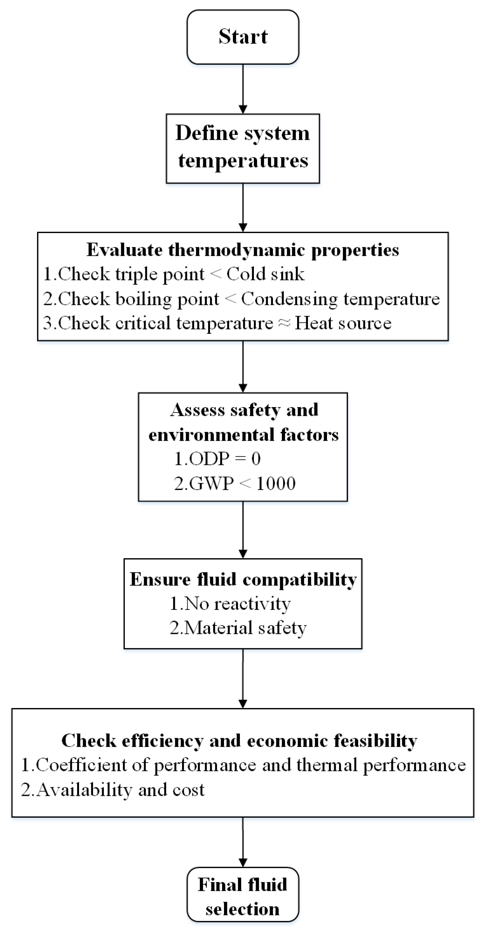
2.2. Working Fluid Selection and Boundary Conditions
3. The Mathematical Model and Verification
3.1. Parameter Hypothesis
- The system operates in a steady state [31].
- The heat exchanger’s minimum heat transfer temperature differential is at least 5 °C [32].
- The subcooling of all cycles is 2 °C [33].
- The pump’s efficiency is 0.85, and the turbine’s isentropic efficiency is 0.85 [34].
- The atmospheric pressure P0 is 100 kPa, and the ambient temperature T0 is 25 °C.
3.2. Thermodynamic Model
3.3. Economic Model
3.4. Environmental Model
3.5. Model Verification
4. Result and Discussion
4.1. System Comparison
4.2. Parameter Analysis
4.3. Multi-Objective Optimization
4.3.1. Optimization Method
- Compared to genetic algorithms, MOPSO typically exhibits a faster convergence speed. Genetic algorithms rely on operations such as selection, crossover, and mutation, which may require multiple generations to arrive at the optimal solution. In contrast, MOPSO leverages collaboration and information sharing among particles to achieve results close to the optimal solution in fewer iterations.
- MOPSO guides its search using the particle’s personal best position (pbest) and the global best position (gbest), effectively balancing global and local search throughout the process. This balance makes it easier to avoid getting trapped in local optima. In comparison, the global search capabilities of genetic algorithms may be influenced by mutation operations and selection methods.
- The algorithm structure of MOPSO is relatively simple, requiring fewer parameter adjustments and avoiding complex crossover and mutation operations. In contrast, genetic algorithms necessitate careful design of these operations. For the complex design of LNG power generation systems, MOPSO offers a more straightforward implementation.
- The optimization problems associated with LNG power generation systems often involve continuous variables, and MOPSO excels in handling such variables. While genetic algorithms can also address continuous optimization problems, they are typically better suited for discrete or mixed-type variable optimization.
- MOPSO incorporates the concept of Pareto optimality, making it well-suited for addressing multi-objective optimization problems. Although genetic algorithms can be applied to multi-objective optimization (e.g., NSGA-II), MOPSO generally demonstrates better convergence and solution diversity.
- Ensure the liquid phase fraction of the working fluid at the pump’s inlet is equal to 1 to avoid steam from entering and damaging the pump.
- Ensure the liquid phase fraction of the working fluid at the turbine inlet is 0 to avoid liquid from entering and harming the turbine. The outlet quality is more than 0.9 to preserve the turbine blades.
- The entire composition of the mixed working fluid for both cycles is equal to 1.
- All three cycles’ evaporation temperatures ought to be higher than their condensation temperatures.
4.3.2. Optimization Results and Comparison
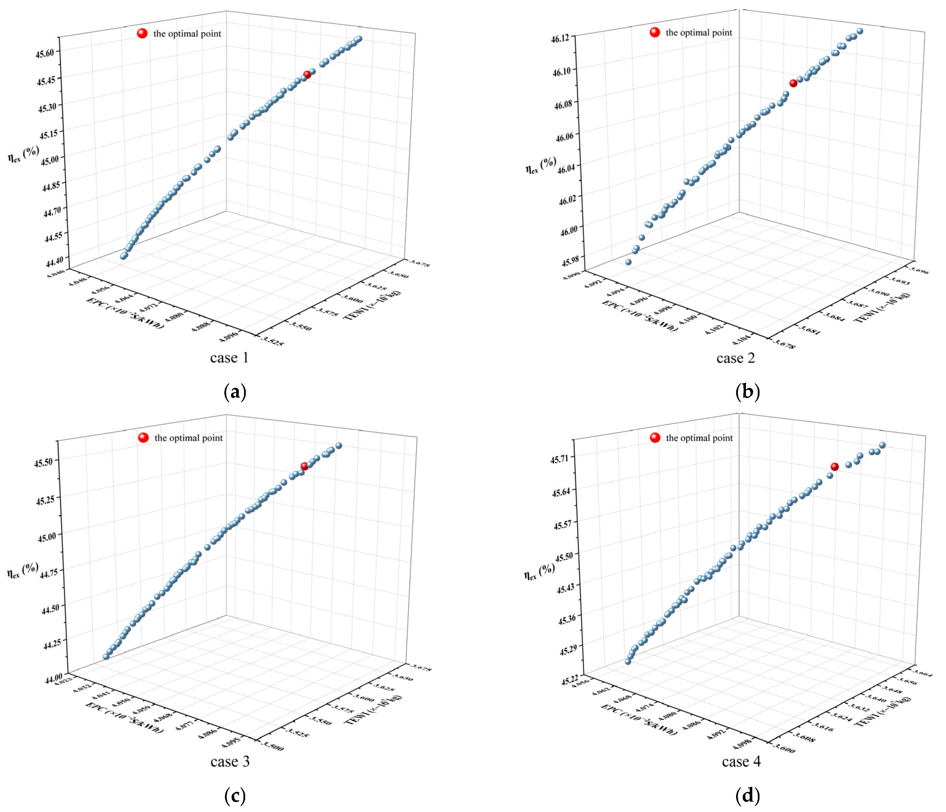
- Determining the weights: Since different evaluation criteria have varying levels of importance in decision-making, it is essential to assign appropriate weights to each criterion. The rationality of the weights directly affects the final decision outcome. This study aims to achieve simultaneous optimization; therefore, equal weights of 1/3 have been assigned to each of the three objectives: exergy efficiency, unit power generation cost, and carbon dioxide emissions.
- Distinguishing between positive and negative indicators in TOPSIS: Some indicators are more desirable when their values are higher (positive indicators). In comparison, others are preferable when their values are lower (negative indicators). When calculating the distance between the ideal and negative ideal solutions, these two types of indicators need to be handled separately. For example, in calculating the distance to the ideal solution, exergy efficiency is a positive indicator—meaning that the higher the value, the better. The closer the exergy efficiency of a solution is to the maximum value (ideal solution), the better the solution. In contrast, unit power generation cost is a negative indicator, meaning that lower values are preferable, and minimizing this cost is the optimization goal. TEWI is a positive indicator, meaning that the greater the reduction in CO2 emissions, the better, as the goal is to minimize emissions.
- The selection of the ideal and negative solutions in TOPSIS is critical for ensuring the accuracy of ranking alternatives. The ideal solution represents the best value for each criterion, while the negative ideal solution represents the worst. The proper definition and selection of these values directly impact the ranking results. For exergy efficiency and TEWI, which are positive indicators, the goal is to maximize their values. Therefore, the maximum value is chosen as the ideal solution, and the minimum value is the negative ideal solution. For unit power generation cost, a negative indicator, the goal is to minimize the value. Thus, the minimum value is selected as the ideal solution, and the maximum value is the negative ideal solution.
- Construct the original decision matrix : This matrix displays the performance of each objective function across different indicators. When using the TOPSIS method, the decision matrix is typically represented through a normalization matrix. This means that the indicator values need to be standardized, converting them completely into a range between 0 and 1.
- Identify the positive ideal solution and the negative ideal solution: The positive ideal solution refers to the solution that is closest to the ideal. In contrast, the negative ideal solution refers to the solution that is farthest from the ideal.
- Calculate the distances of each alternative from the positive ideal solution and the negative ideal solution .where , represents the index of the non-dominated solutions, and represents the number of objective functions.
- Calculate the similarity of each alternative .
- Rank the alternatives based on the descending order of : the lower the similarity of an alternative, the greater its distance from the optimal solution; conversely, the higher the similarity, the closer it is to the optimal solution.
4.4. Exergy Loss Analysis before and after Optimization
4.5. Comparison with Existing Systems
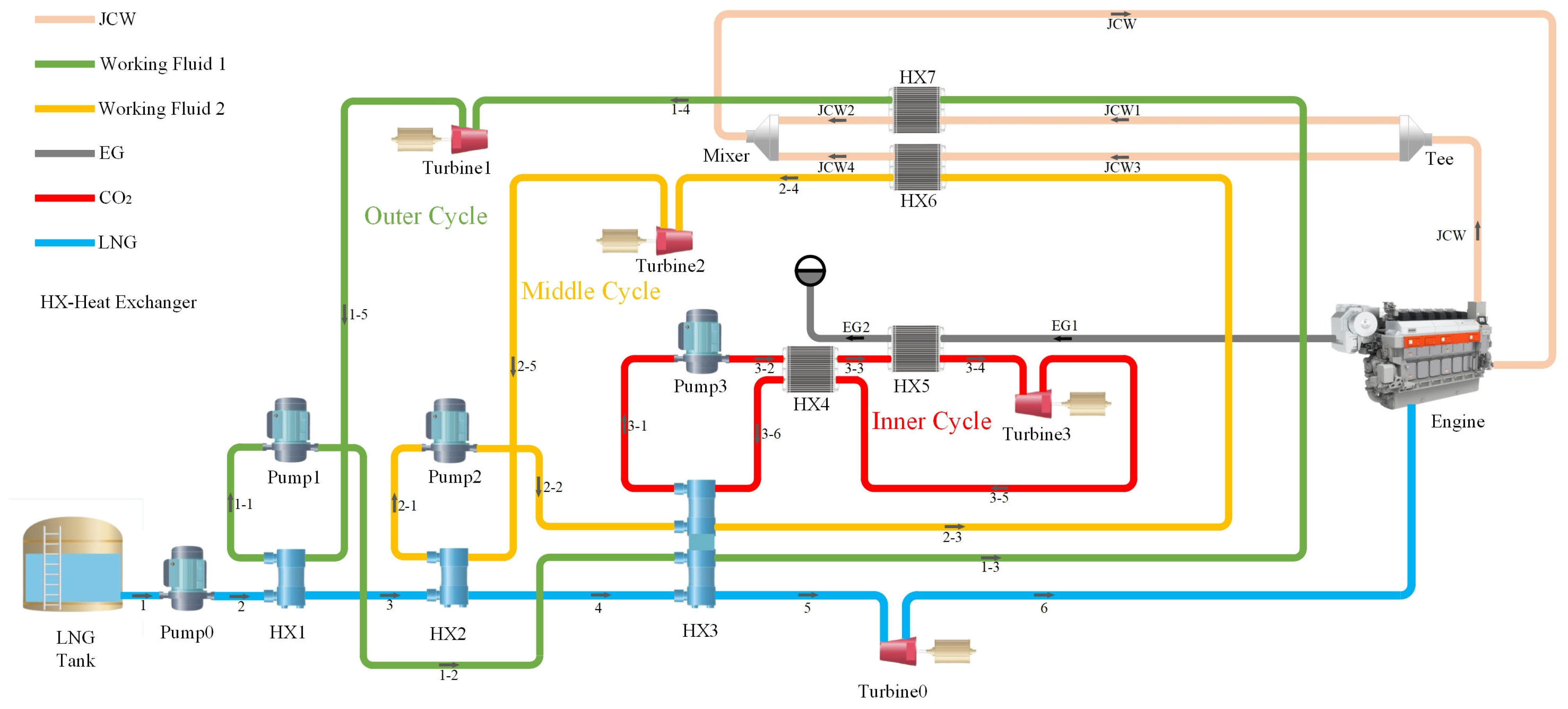
- The innovative method in this study has evident advantages in terms of net power generation performance since it uses a three-layer layered structure, with each layer making full use of the ship’s waste heat for power generation and the LNG pressure exergy.
- The exergy efficiency of this study has an advantage. Still, it is not the maximum because the three-objective optimization used in this study limits the maximizing of exergy efficiency to some amount to ensure good synchronization of EPC and TEWI. In the reference [33], exergy efficiency is optimized for a single goal, resulting in the highest exergy efficiency among the four systems, demonstrating that multi-objective optimization might render certain performance suboptimal to some extent. However, due to the simultaneous optimization of the three performance metrics, the overall performance of the system in this study still exceeds that of the system in reference [33].
- Using multi-objective optimization, the new system’s EPC is minimized. For complicated systems [22,33] analogous to this system, the EPC of this new system offers substantial benefits. However, compared to the simple system [9], the new system’s total input cost is unavoidably higher. Still, the unit power generation cost is much lower due to the obvious increase in power generation. Hence, the novel multistage nested structure of this system is worth noting.
- It is worth noting that there is little discussion of TEWI in the present literature on LNG power production systems. As a result, introducing TEWI as an optimization objective improves the system’s thermodynamic and economic performance while increasing the amount of carbon dioxide emissions that can be decreased, making the system more ecologically friendly. This emphasizes the advantages of the new system.
5. Conclusions
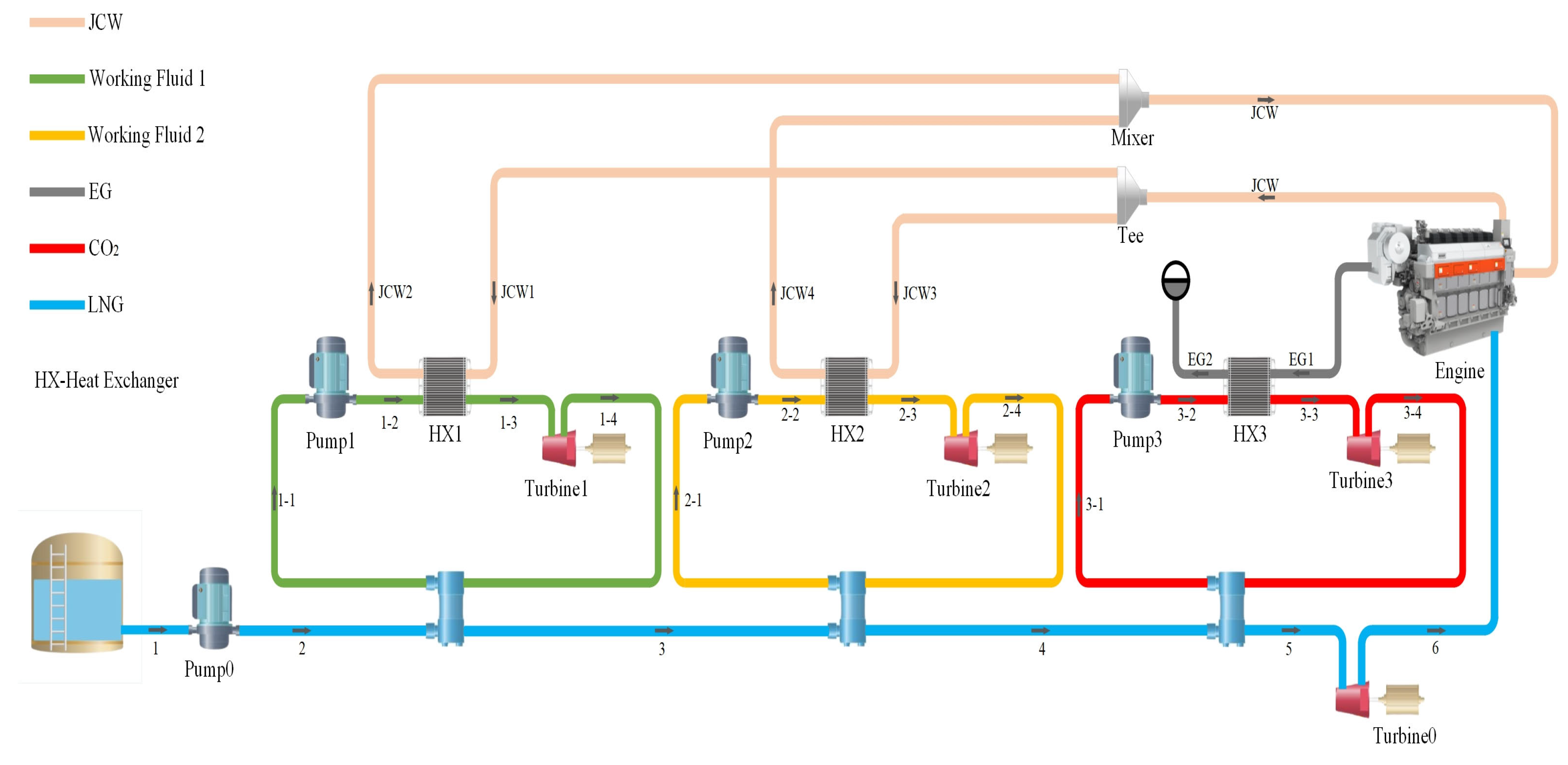
- The unoptimized initial system generates 427.43 kW of power, with an exergy efficiency of 35.57%, a power generation cost of $0.04569 per kWh, and reduces CO₂ emissions by 27,380 tons. It offers substantial advantages over the three-stage parallel LNG power generation technology.
- Case 2 demonstrated the best performance in terms of net power output, exergy efficiency, and Total Equivalent Warming Impact (TEWI), using R170 (22.66%) and R1150 (77.34%) as the outer cycle working fluids and R170 (90.86%) and R1270 (9.14%) for the middle cycle.
- After optimization, the system achieved a net power output of 575.75 kW, an exergy efficiency of 46.09%, a power generation cost of $0.04099 per kWh, and a reduction in CO₂ emissions by 36,910 tons. This represents a 34.7% increase in net power, a 10.52% improvement in exergy efficiency, a 10.23% reduction in EPC, and a 34.81% decrease in TEWI.
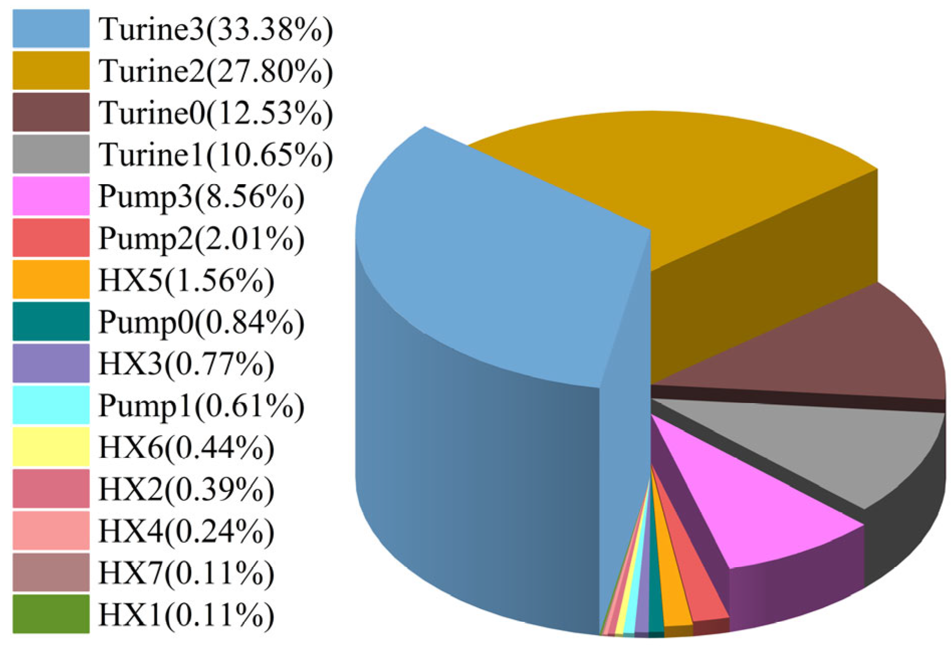
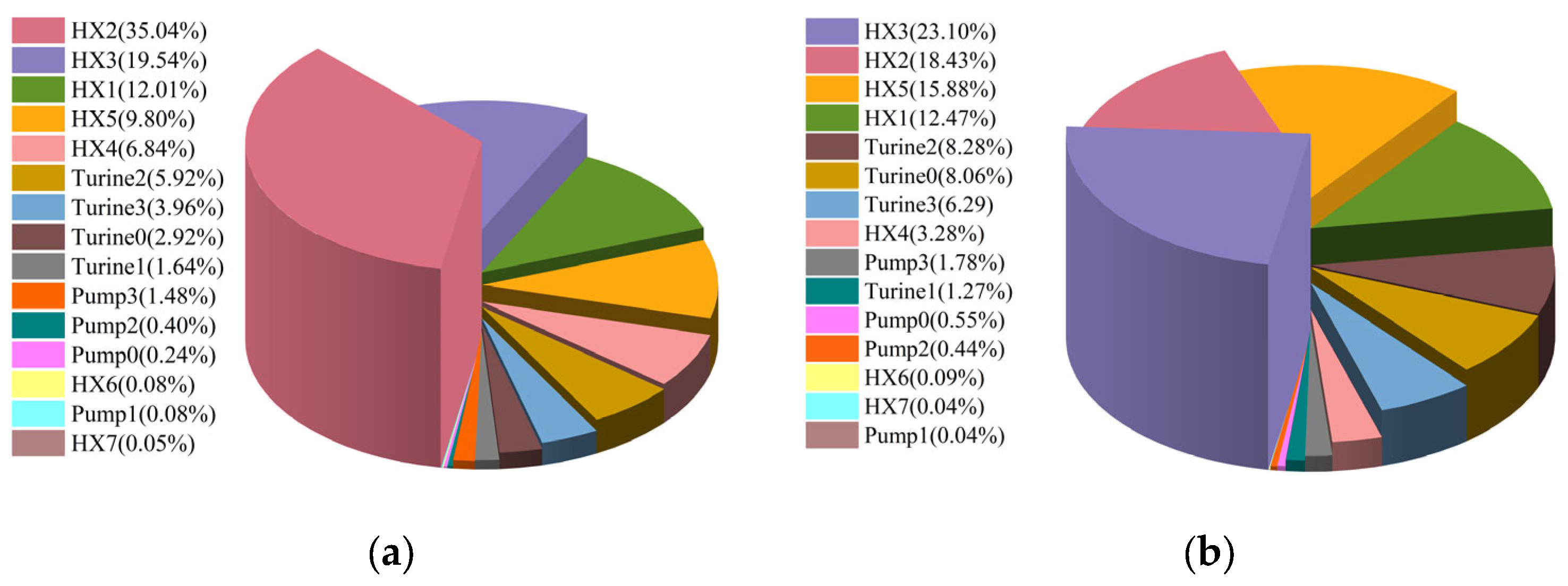
- The turbine accounted for the highest proportion of costs, followed by the pump. Exergy loss analysis before and after optimization revealed that the component with the highest exergy loss ratio was HX2, and it also showed the most significant reduction in exergy loss after optimization, largely due to the optimization of LNG vaporization temperature.
- Compared to similar systems in the literature, this system demonstrates clear advantages in both thermodynamic and economic performance. It is also more environmentally friendly, with significant consideration of environmental factors.
- The system’s waste heat recovery has not been fully realized due to limitations in cooling capacity at the cold end. To maximize system performance, future studies could consider incorporating external cooling sources, such as seawater, to optimize waste heat recovery on the ship.
- This study primarily employed commercial software for simulations, overlooking some factors that may have minor impacts, resulting in a deviation between the simulation results and actual conditions. To verify the accuracy of these results, subsequent research could establish a corresponding experimental system.
- The analysis of the cyclic system did not account for the specific structures of the equipment, thus neglecting aspects such as geometry, materials used, and adaptability. Therefore, future research should conduct in-depth analyses of individual components within the system.
Author Contributions
Funding
Institutional Review Board Statement
Informed Consent Statement
Data Availability Statement
Conflicts of Interest
Nomenclature
| specific entropy (kJ/kg/K) | |
| specific enthalpy (kJ/kg) | |
| Specific exergy (kJ/kg) | |
| electricity price for ships ($/kWh) | |
| component cost ($) | |
| system operating life (year) | |
| annual operating time (hour) | |
| annual interest rate | |
| heat transfer area (m2) | |
| cost of operation and maintenance | |
| annual leakage rate | |
| annual power generation(kWh/year) | |
| initial charging amount of fluid (kg) | |
| temperature (°C) | |
| pressure (kPa) | |
| mass fraction | |
| mass flow (kg/h) | |
| exergy (kW) | |
| output power or power consumption (kW) | |
| total net output power (kW) | |
| power generation per unit mass flow of LNG (kW/kg/s) | |
| Greeks symbols | |
| system exergy efficiency (%) | |
| GWP for electricity production (kg/kWh) | |
| Subscripts | |
| inlet | |
| pay for | |
| 0 | reference state |
| total | |
| T | turbine |
| P | pump |
| HX | heat exchanger |
| Abbreviations | |
| ORC | organic Rankine cycle |
| FSRU | floating storage regasification unit |
| JCW | jacket cooling water |
| LNG | liquefied natural gas |
| EG | exhaust gases |
| CRF | capital recovery factor |
| EPC | electricity production cost ($/kWh) |
| PBP | payback period (year) |
| GWP | global warming potential |
| ODP | ozone depletion potential |
| TEWI | total equivalent warming impact |
| MOPSO | Multi-objective particle swarm optimization algorithm |
| TOPSIS | technique for order preference by similarity to an ideal solution |
References
- Burel, F.; Taccani, R.; Zuliani, N. Improving Sustainability of Maritime Transport through Utilization of Liquefied Natural Gas (LNG) for Propulsion. Energy 2013, 57, 412–420. [Google Scholar] [CrossRef]
- Li, P.; Li, J.; Pei, G.; Munir, A.; Ji, J. A Cascade Organic Rankine Cycle Power Generation System Using Hybrid Solar Energy and Liquefied Natural Gas. Sol. Energy 2016, 127, 136–146. [Google Scholar] [CrossRef]
- Zhang, M.-G.; Zhao, L.-J.; Liu, C.; Cai, Y.-L.; Xie, X.-M. A Combined System Utilizing LNG and Low-Temperature Waste Heat Energy. Appl. Therm. Eng. 2016, 101, 525–536. [Google Scholar] [CrossRef]
- Bao, J.; Yuan, T.; Zhang, L.; Zhang, N.; Zhang, X.; He, G. Comparative Study of Liquefied Natural Gas (LNG) Cold Energy Power Generation Systems in Series and Parallel. Energy Convers. Manag. 2019, 184, 107–126. [Google Scholar] [CrossRef]
- Ozen, D.N.; Uçar, İ. Energy, Exergy, and Exergo-economic Analysis of a Novel Combined Power System Using the Cold Energy of Liquified Natural Gas (LNG). Environ. Prog. Sustain. Energy 2020, 39, e13377. [Google Scholar] [CrossRef]
- Xu, J. A CO2 Cryogenic Capture System for Flue Gas of an LNG-Fired Power Plant. Int. J. Hydrogen Energ. 2017, 42, 18674–18680. [Google Scholar] [CrossRef]
- Baldasso, E.; Mondejar, M.E.; Mazzoni, S.; Romagnoli, A.; Haglind, F. Potential of Liquefied Natural Gas Cold Energy Recovery on Board Ships. J. Clean. Prod. 2020, 271, 122519. [Google Scholar] [CrossRef]
- Noor Akashah, M.H.; Mohammad Rozali, N.E.; Mahadzir, S.; Liew, P.Y. Utilization of Cold Energy from LNG Regasification Process: A Review of Current Trends. Processes 2023, 11, 517. [Google Scholar] [CrossRef]
- Tian, Z.; Zeng, W.; Gu, B.; Zhang, Y.; Yuan, X. Energy, Exergy, and Economic (3E) Analysis of an Organic Rankine Cycle Using Zeotropic Mixtures Based on Marine Engine Waste Heat and LNG Cold Energy. Energy Convers. Manag. 2021, 228, 113657. [Google Scholar] [CrossRef]
- Tian, Z.; Yue, Y.; Gu, B.; Gao, W.; Zhang, Y. Thermo-economic Analysis and Optimization of a Combined Organic Rankine Cycle (orc) System with lng Cold Energy and Waste Heat Recovery of Dual-fuel Marine Engine. Int. J. Energy Res. 2020, 44, 9974–9994. [Google Scholar] [CrossRef]
- Soffiato, M.; Frangopoulos, C.A.; Manente, G.; Rech, S.; Lazzaretto, A. Design Optimization of ORC Systems for Waste Heat Recovery on Board a LNG Carrier. Energy Convers. Manag. 2015, 92, 523–534. [Google Scholar] [CrossRef]
- Lee, S.; Choi, B.C. Thermodynamic Assessment of Integrated Heat Recovery System Combining Exhaust-Gas Heat and Cold Energy for LNG Regasification Process in FSRU Vessel. J. Mech. Sci. Technol. 2016, 30, 1389–1398. [Google Scholar] [CrossRef]
- Yu, P.; Liu, H.; Zhou, S.; Che, D. Thermodynamic Analysis of a Cryogenic Power Generation System Recovering Both Sensible Heat and Latent Heat of Flue Gas. Energy Convers. Manag. 2021, 227, 113615. [Google Scholar] [CrossRef]
- Yao, S.; Li, C.; Wei, Y. Design and Optimization of a Zero Carbon Emission System Integrated with the Utilization of Marine Engine Waste Heat and LNG Cold Energy for LNG-Powered Ships. Appl. Therm. Eng. 2023, 231, 120976. [Google Scholar] [CrossRef]
- Lecompte, S.; Ameel, B.; Ziviani, D.; Van Den Broek, M.; De Paepe, M. Exergy Analysis of Zeotropic Mixtures as Working Fluids in Organic Rankine Cycles. Energy Convers. Manag. 2014, 85, 727–739. [Google Scholar] [CrossRef]
- Lee, S. Multi-Parameter Optimization of Cold Energy Recovery in Cascade Rankine Cycle for LNG Regasification Using Genetic Algorithm. Energy 2017, 118, 776–782. [Google Scholar] [CrossRef]
- Li, Y.-R.; Du, M.-T.; Wu, C.-M.; Wu, S.-Y.; Liu, C. Potential of Organic Rankine Cycle Using Zeotropic Mixtures as Working Fluids for Waste Heat Recovery. Energy 2014, 77, 509–519. [Google Scholar] [CrossRef]
- Oyewunmi, O.; Markides, C. Thermo-Economic and Heat Transfer Optimization of Working-Fluid Mixtures in a Low-Temperature Organic Rankine Cycle System. Energies 2016, 9, 448. [Google Scholar] [CrossRef]
- Yang, M.-H. Payback Period Investigation of the Organic Rankine Cycle with Mixed Working Fluids to Recover Waste Heat from the Exhaust Gas of a Large Marine Diesel Engine. Energy Convers. Manag. 2018, 162, 189–202. [Google Scholar] [CrossRef]
- He, T.; Ma, H.; Ma, J.; Mao, N.; Liu, Z. Effects of Cooling and Heating Sources Properties and Working Fluid Selection on Cryogenic Organic Rankine Cycle for LNG Cold Energy Utilization. Energy Convers. Manag. 2021, 247, 114706. [Google Scholar] [CrossRef]
- Choi, H.W.; Na, S.-I.; Hong, S.B.; Chung, Y.; Kim, D.K.; Kim, M.S. Optimal Design of Organic Rankine Cycle Recovering LNG Cold Energy with Finite Heat Exchanger Size. Energy 2021, 217, 119268. [Google Scholar] [CrossRef]
- Han, F.; Wang, Z.; Ji, Y.; Li, W.; Sundén, B. Energy Analysis and Multi-Objective Optimization of Waste Heat and Cold Energy Recovery Process in LNG-Fueled Vessels Based on a Triple Organic Rankine Cycle. Energy Convers. Manag. 2019, 195, 561–572. [Google Scholar] [CrossRef]
- Liu, Y.; Guo, K. A Novel Cryogenic Power Cycle for LNG Cold Energy Recovery. Energy 2011, 36, 2828–2833. [Google Scholar] [CrossRef]
- Zhao, P.; Wang, J.; Dai, Y.; Gao, L. Thermodynamic Analysis of a Hybrid Energy System Based on CAES System and CO2 Transcritical Power Cycle with LNG Cold Energy Utilization. Appl. Therm. Eng. 2015, 91, 718–730. [Google Scholar] [CrossRef]
- Sun, Z.; Lai, J.; Wang, S.; Wang, T. Thermodynamic Optimization and Comparative Study of Different ORC Configurations Utilizing the Exergies of LNG and Low Grade Heat of Different Temperatures. Energy 2018, 147, 688–700. [Google Scholar] [CrossRef]
- Sun, X.; Yao, S.; Xu, J.; Feng, G.; Yan, L. Design and Optimization of a Full-Generation System for Marine LNG Cold Energy Cascade Utilization. J. Therm. Sci. 2020, 29, 587–596. [Google Scholar] [CrossRef]
- Xiao, X.; Xu, X.; Wang, Z.; Liu, C.; He, Y. Research on a Novel Combined Cooling and Power Scheme for LNG-Powered Ship. J. Mar. Sci. Eng. 2023, 11, 592. [Google Scholar] [CrossRef]
- Meng, N.; Li, T.; Gao, X.; Liu, Q.; Li, X.; Gao, H. Thermodynamic and Techno-Economic Performance Comparison of Two-Stage Series Organic Rankine Cycle and Organic Rankine Flash Cycle for Geothermal Power Generation from Hot Dry Rock. Appl. Therm. Eng. 2022, 200, 117715. [Google Scholar] [CrossRef]
- Yu, H.; Kim, D.; Gundersen, T. A Study of Working Fluids for Organic Rankine Cycles (ORCs) Operating across and below Ambient Temperature to Utilize Liquefied Natural Gas (LNG) Cold Energy. Energy 2019, 167, 730–739. [Google Scholar] [CrossRef]
- Bao, J.; Yuan, T.; Song, C.; Zhang, X.; Zhang, N.; He, G. Thermodynamic Analysis of a New Double-Pressure Condensation Power Generation System Recovering LNG Cold Energy for Hydrogen Production. Int. J. Hydrogen Energ. 2019, 44, 17649–17661. [Google Scholar] [CrossRef]
- Chen, K.; Yu, H.; Fan, G.; Zhang, Y.; Dai, Y. Multi-Objective Optimization of a Novel Combined Parallel Power Generation System Using CO2 and N2 for Cascade Recovery of LNG Cryogenic Energy. Energy Convers. Manag. 2022, 256, 115395. [Google Scholar] [CrossRef]
- Kang, L.; Tang, J.; Liu, Y. Optimal Design of Organic Rankine Cycle System for Multi-Source Waste Heat Recovery Involving Multi-Period Operation. Energy 2021, 235, 121379. [Google Scholar] [CrossRef]
- Yao, S.; Wei, Y.; Zhang, Z.; Yang, Y. Design Study on the Integrated Utilization System of Medium Temperature Waste Heat and LNG Vaporization Cold Energy for 200000 DWT LNG-Powered Vessels. Therm. Sci. 2023, 27, 1289–1299. [Google Scholar] [CrossRef]
- Choi, B.C.; Kim, Y.M. Thermodynamic Analysis of a Dual Loop Heat Recovery System with Trilateral Cycle Applied to Exhaust Gases of Internal Combustion Engine for Propulsion of the 6800 TEU Container Ship. Energy 2013, 58, 404–416. [Google Scholar] [CrossRef]
- Mohammadi, K.; McGowan, J.G. A Thermo-Economic Analysis of a Combined Cooling System for Air Conditioning and Low to Medium Temperature Refrigeration. J. Clean. Prod. 2019, 206, 580–597. [Google Scholar] [CrossRef]
- Wang, X.; Dai, Y. Exergoeconomic Analysis of Utilizing the Transcritical CO2 Cycle and the ORC for a Recompression Supercritical CO2 Cycle Waste Heat Recovery: A Comparative Study. Appl. Energy 2016, 170, 193–207. [Google Scholar] [CrossRef]
- Li, T.; Meng, N.; Liu, J.; Zhu, J.; Kong, X. Thermodynamic and Economic Evaluation of the Organic Rankine Cycle (ORC) and Two-Stage Series Organic Rankine Cycle (TSORC) for Flue Gas Heat Recovery. Energy Convers. Manag. 2019, 183, 816–829. [Google Scholar] [CrossRef]
- Yang, M.-H.; Yeh, R.-H. The Effects of Composition Ratios and Pressure Drops of R245fa/R236fa Mixtures on the Performance of an Organic Rankine Cycle System for Waste Heat Recovery. Energy Convers. Manag. 2018, 175, 313–326. [Google Scholar] [CrossRef]
- Su, Z.; Ouyang, T.; Chen, J.; Xu, P.; Tan, J.; Chen, N.; Huang, H. Green and Efficient Configuration of Integrated Waste Heat and Cold Energy Recovery for Marine Natural Gas/Diesel Dual-Fuel Engine. Energy Convers. Manag. 2020, 209, 112650. [Google Scholar] [CrossRef]
- Llopis, R.; Calleja-Anta, D.; Maiorino, A.; Nebot-Andrés, L.; Sánchez, D.; Cabello, R. Tewi Analysis of a Stand-Alone Refrigeration System Using Low-GWP Fluids with Leakage Ratio Consideration. Int. J. Refrig. 2020, 118, 279–289. [Google Scholar] [CrossRef]
- Staubach, D.; Michel, B.; Revellin, R. Refrigerant Selection from an Economic and TEWI Analysis of Cascade Refrigeration Systems in Europe Based on Annual Weather Data. Appl. Therm. Eng. 2023, 230, 120747. [Google Scholar] [CrossRef]
- Islam, M.A.; Srinivasan, K.; Thu, K.; Saha, B.B. Assessment of Total Equivalent Warming Impact (TEWI) of Supermarket Refrigeration Systems. Int. J. Hydrogen Energ. 2017, 42, 26973–26983. [Google Scholar] [CrossRef]
- Collings, P.; Yu, Z.; Wang, E. A Dynamic Organic Rankine Cycle Using a Zeotropic Mixture as the Working Fluid with Composition Tuning to Match Changing Ambient Conditions. Appl. Energy 2016, 171, 581–591. [Google Scholar] [CrossRef]
- Sun, Z.; Zhang, H.; Zhang, T.; Lin, L.; Lin, K. Optimizations and Comparison of Three Two-Stage Rankine Cycles under Different Heat Source Temperatures and NG Distribution Pressures. Energy Convers. Manag. 2020, 209, 112655. [Google Scholar] [CrossRef]
- Yao, S.; Zhang, Z.; Wei, Y.; Liu, R. Integrated Design and Optimization Research of LNG Cold Energy and Main Engine Exhaust Heat Utilization for LNG Powered Ships. Case. Stud. Therm. Eng. 2022, 33, 101976. [Google Scholar] [CrossRef]
- Coello, C.A.C.; Pulido, G.T.; Lechuga, M.S. Handling Multiple Objectives with Particle Swarm Optimization. IEEE Trans. Evol. Computat. 2004, 8, 256–279. [Google Scholar] [CrossRef]
- Ahmadi, M.H.; Hosseinzade, H.; Sayyaadi, H.; Mohammadi, A.H.; Kimiaghalam, F. Application of the Multi-Objective Optimization Method for Designing a Powered Stirling Heat Engine: Design with Maximized Power, Thermal Efficiency and Minimized Pressure Loss. Renew Energy 2013, 60, 313–322. [Google Scholar] [CrossRef]



| Working Fluid | Triple Point Temperature (°C) | Normal Boiling Temperature (°C) | Critical Temperature (°C) | OPD | GWP |
|---|---|---|---|---|---|
| R170 | −182.78 | −88.75 | 32.17 | 0 | 20 |
| R1150 | −169.21 | −103.71 | 9.17 | 0 | 1.8 |
| R1270 | −185.23 | −47.69 | 92.44 | 0 | 3.3 |
| R290 | −187.63 | −42.08 | 96.67 | 0 | 3.3 |
| No. | The Outer Cycle’s Zeotropic Mixture | The Outer Cycle’s Zeotropic Mixture |
|---|---|---|
| Case 1 | R170/R1150 | R170/R1150 |
| Case 2 | R170/R1150 | R170/R1270 |
| Case 3 | R170/R1270 | R170/R1150 |
| Case 4 | R170/R1270 | R170/R1270 |
| Parameter | Value | |
|---|---|---|
| EG | Composition (mass fraction) | N2 (0.7385), CO2 (0.1048), H2O (0.0825), O2 (0.0742) |
| Mass flow rate (kg/h) | 111,541 | |
| Inlet temperature (°C) | 230 | |
| Outlet temperature (°C) | 100 | |
| JCW | Composition (mass fraction) | Water (1) |
| Mass flow rate (kg/h) | 96,197 | |
| Inlet temperature (°C) | 95 | |
| Outlet temperature (°C) | 75 | |
| LNG | Composition (mass fraction) | Methane (1) |
| Mass flow rate (kg/h) | 3600 | |
| Outlet temperature (°C) | 0 | |
| Outlet pressure (kPa) | 592 |
| Items | Specific Items | Energy Analysis | Exergy Analysis |
|---|---|---|---|
| Heat exchanger | HX1 | ||
| HX2 | |||
| HX3 | |||
| HX4 | |||
| HX5 | |||
| HX6 | |||
| HX7 | |||
| Pump | Pump0 | ||
| Pump1 | |||
| Pump2 | |||
| Pump3 | |||
| Turbine | Turbine0 | ||
| Turbine1 | |||
| Turbine2 | |||
| Turbine3 |
| Component | Capital Cost Function |
|---|---|
| Turbine | |
| Pump | |
| Heat Exchanger |
| Process Parameter | Reference [45] | Simulation Results | Error (%) |
|---|---|---|---|
| Working fluid flow (kg/h) | 3234 | 3249 | 0.46 |
| Working fluid temperature (°C) | 5 | 4.96 | 0.8 |
| Working fluid pressure (kPa) | 3900 | 3900 | 0 |
| Net out power | 5124 | 5172 | 0.94 |
| System exergy efficiency (%) | 55.76 | 55.79 | 0.05 |
| State | Component | Temperature (°C) | Pressure (kPa) | Stream Flow (kg/h) |
|---|---|---|---|---|
| 1 | LNG | −162.00 | 100 | 3600.00 |
| 2 | LNG | −161.60 | 1000 | 3600.00 |
| 3 | NG | −130.00 | 1000 | 3600.00 |
| 4 | NG | −90.00 | 1000 | 3600.00 |
| 5 | NG | 26.99 | 1000 | 3600.00 |
| 6 | NG | 0.00 | 592 | 3600.00 |
| 1-1 | R170 | −91.01 | 100 | 782.75 |
| 1-2 | R170 | −89.28 | 3500 | 782.75 |
| 1-3 | R170 | 60.00 | 3500 | 782.75 |
| 1-4 | R170 | 90.00 | 3500 | 782.75 |
| 1-5 | R170 | −59.24 | 100 | 782.75 |
| JCW1 | JCW | 95.00 | 100 | 661.62 |
| JCW2 | JCW | 75.00 | 100 | 661.62 |
| 2-1 | R170 | −77.07 | 200 | 3602.39 |
| 2-2 | R170 | −74.89 | 4000 | 3602.39 |
| 2-3 | R170 | 70.00 | 4000 | 3602.39 |
| 2-4 | R170 | 90.00 | 4000 | 3602.39 |
| 2-5 | R170 | −43.58 | 200 | 3602.39 |
| JCW3 | JCW | 95.00 | 100 | 2103.23 |
| JCW4 | JCW | 75.00 | 100 | 2103.23 |
| 3-1 | CO2 | 26.66 | 7000 | 16,230.03 |
| 3-2 | CO2 | 45.92 | 15,000 | 16,230.03 |
| 3-3 | CO2 | 66.28 | 15,000 | 16,230.03 |
| 3-4 | CO2 | 225.00 | 15,000 | 16,230.03 |
| 3-5 | CO2 | 156.51 | 7000 | 16,230.03 |
| 3-6 | CO2 | 100.00 | 7000 | 16,230.03 |
| EG1 | EG | 230.00 | 100 | 30,883.13 |
| EG2 | EG | 100.00 | 100 | 30,883.13 |
| State | Component | Temperature (°C) | Pressure (kPa) | Stream Flow (kg/h) |
|---|---|---|---|---|
| 1 | LNG | −162.00 | 100 | 3600.00 |
| 2 | LNG | −161.60 | 1000 | 3600.00 |
| 3 | NG | −130.00 | 1000 | 3600.00 |
| 4 | NG | −90.00 | 1000 | 3600.00 |
| 5 | NG | 26.99 | 1000 | 3600.00 |
| 6 | NG | 0.00 | 592 | 3600.00 |
| 1-1 | R170 | −91.01 | 100 | 782.75 |
| 1-2 | R170 | −89.28 | 3500 | 782.75 |
| 1-3 | R170 | 90.00 | 3500 | 782.75 |
| 1-4 | R170 | −59.24 | 3500 | 782.75 |
| JCW1 | JCW | 95.00 | 100 | 6827.15 |
| JCW2 | JCW | 75.00 | 100 | 6827.15 |
| 2-1 | R170 | −77.07 | 200 | 3602.39 |
| 2-2 | R170 | −74.89 | 4000 | 3602.39 |
| 2-3 | R170 | 90.00 | 4000 | 3602.39 |
| 2-4 | R170 | −43.58 | 4000 | 3602.39 |
| JCW3 | JCW | 95.00 | 100 | 29,559.84 |
| JCW4 | JCW | 75.00 | 100 | 29,559.84 |
| 3-1 | CO2 | 26.66 | 7000 | 3165.49 |
| 3-2 | CO2 | 45.92 | 15,000 | 3165.49 |
| 3-3 | CO2 | 225.00 | 15,000 | 3165.495 |
| 3-4 | CO2 | 156.50 | 15,000 | 3165.49 |
| EG1 | EG | 230.00 | 100 | 7530.92 |
| EG2 | EG | 100.00 | 100 | 7530.92 |
| Parameter | The Three-Level Nested System | The Three-Level Parallel System |
|---|---|---|
| (kW) | 427.43 | 296.10 |
| (%) | 35.57 | 16.10 |
| EPC(×10−2 $/kWh) | 4.569 | 4.585 |
| TEWI (×−107 kg) | 2.738 | 1.553 |
| PBP (years) | 2.853 | 2.863 |
| Parameter | Value |
|---|---|
| Maximum Number of Iterations | 800 |
| Population Size | 800 |
| Repository Size | 70 |
| Inertia Weight | 0.5 |
| Intertia Weight Damping Rate | 0.99 |
| Personal Learning Coefficient | 1 |
| Global Learning Coefficient | 2 |
| Decision Variables | Ranges |
|---|---|
| T4 (°C) | [−130, 0] |
| P4 (kPa) | [500, 5000] |
| P1-1 (kPa) | [100, 10,000] |
| P1-4 (kPa) | [100, 10,000] |
| P2-1 (kPa) | [100, 10,000] |
| P2-4 (kPa) | [100, 10,000] |
| P3-1 (kPa) | [600, 7300] |
| P3-4 (kPa) | [7300, 20,000] |
| [0, 1] | |
| [0, 1] |
| Parameter | Case0 | Case2 | Case3 |
|---|---|---|---|
| T4 (°C) | −90 | −69.18 | −75.24 |
| P4 (kPa) | 1000 | 2028.28 | 1883.63 |
| P1-1 (kPa) | 100 | 157.97 | 206.37 |
| P1-4 (kPa) | 3500 | 2011.48 | 3115.81 |
| P2-1 (kPa) | 200 | 132.04 | 101.75 |
| P2-4 (kPa) | 4000 | 3261.51 | 2891.87 |
| P3-1 (kPa) | 7000 | 5809.88 | 5711.31 |
| P3-4 (kPa) | 15,000 | 18,781.44 | 19,119.55 |
| (%) | 100 | 22.21 | 70.36% |
| (%) | 100 | 90.86 | 96.10% |
| (kW) | 427.43 | 575.75 | 566.14 |
| (%) | 35.57 | 46.09 | 45.41 |
| (×106 $) | 1.315 | 1.590 | 1.552 |
| EPC (×10−2 $/kWh) | 4.569 | 4.099 | 4.070 |
| PBP (year) | 2.853 | 2.548 | 2.530 |
| TEWI (−107 kgCO2) | 2.738 | 3.691 | 3.629 |
| Items | This Study | Reference [22] | Reference [9] | Reference [33] | |
|---|---|---|---|---|---|
| Heat source | JCW + EG | JCW + EG | JCW + EG | EG | |
| Configuration | Three-level nested power generation+ Direct expansion | A triple ORC+ Direct expansion | Parallel two-stage ORC | An ORC with a two-stage booster and three-stage lateral nesting | |
| Optimization | Triple objective | Dual objective | Single objective | Single objective | |
| (kW/kg/s) | 575.75 | 317 | 241 | 255 | |
| (%) | 46.09 | 34.63 | 23 | 54 | |
| ×102 $/kWh) | 4.099 | 12.7 | 6.5 | 9.5 | |
| The proportion of waste heat recovery (%) | EG | 2.67 | 6.8 | 0.3 | - |
| JCW | 31.18 | 22.9 | 25.4 | 3.1 |
Disclaimer/Publisher’s Note: The statements, opinions and data contained in all publications are solely those of the individual author(s) and contributor(s) and not of MDPI and/or the editor(s). MDPI and/or the editor(s) disclaim responsibility for any injury to people or property resulting from any ideas, methods, instructions or products referred to in the content. |
© 2024 by the authors. Licensee MDPI, Basel, Switzerland. This article is an open access article distributed under the terms and conditions of the Creative Commons Attribution (CC BY) license (https://creativecommons.org/licenses/by/4.0/).
Share and Cite
Chen, Z.; Yang, X.; Zou, J.; Lei, Q.; Yan, B. Simultaneous Optimization of Exergy and Economy and Environment (3E) for a Multistage Nested LNG Power Generation System. J. Mar. Sci. Eng. 2024, 12, 1850. https://doi.org/10.3390/jmse12101850
Chen Z, Yang X, Zou J, Lei Q, Yan B. Simultaneous Optimization of Exergy and Economy and Environment (3E) for a Multistage Nested LNG Power Generation System. Journal of Marine Science and Engineering. 2024; 12(10):1850. https://doi.org/10.3390/jmse12101850
Chicago/Turabian StyleChen, Zhenzhen, Xinglin Yang, Junhu Zou, Qiang Lei, and Bin Yan. 2024. "Simultaneous Optimization of Exergy and Economy and Environment (3E) for a Multistage Nested LNG Power Generation System" Journal of Marine Science and Engineering 12, no. 10: 1850. https://doi.org/10.3390/jmse12101850
APA StyleChen, Z., Yang, X., Zou, J., Lei, Q., & Yan, B. (2024). Simultaneous Optimization of Exergy and Economy and Environment (3E) for a Multistage Nested LNG Power Generation System. Journal of Marine Science and Engineering, 12(10), 1850. https://doi.org/10.3390/jmse12101850


