Article

Gas–Water–Sand Inflow Patterns and Completion Optimization in Hydrate Wells with Different Sand Control Completions

1
Key Laboratory of Unconventional Oil & Gas Development, Ministry of Education, Qingdao 266580, China
2
School of Petroleum Engineering, China University of Petroleum (East China), Qingdao 266580, China
3
Guangzhou Marine Geological Survey, China Geological Survey, Guangzhou 511466, China
*
Author to whom correspondence should be addressed.
J. Mar. Sci. Eng. 2024, 12(11), 2071; https://doi.org/10.3390/jmse12112071
Submission received: 29 October 2024 / Revised: 13 November 2024 / Accepted: 13 November 2024 / Published: 15 November 2024
(This article belongs to the Special Issue Advances in Marine Gas Hydrate Exploration and Discovery)

Abstract

:
Sand production poses a significant problem for marine natural gas hydrate efficient production. However, the bottom hole gas–water–sand inflow pattern remains unclear, hindering the design of standalone screen and gravel packing sand control completions. Therefore, gas–water–sand inflow patterns were studied in horizontal and vertical wells with the two completions. The experimental results showed that gas–water stratification occurred in horizontal and vertical standalone screen wells. The gas–water interface changed dynamically, leading to an uneven screen plugging, with severe plugging at the bottom and high permeability at the top. The high sand production rate and low well deviation angle exacerbated screen plugging, resulting in a faster rising rate of the gas–water interface. The screen plugging degree initially decreased and then increased as the gas–water ratio increased, resulting in the corresponding variation in the gas–water interface rising rate. Conversely, gas–water stratification did not occur in the gravel packing well because of the pore throat formed between the packing gravels. However, the impact of gas and water led to gravel rearrangement and the formation of erosion holes, causing sand control failure. A higher gas–water ratio and lower packing degree could result in more severe destabilization. Therefore, for the standalone screen completion, sand control accuracy should be designed at different levels according to the uneven plugging degree of the screen. For the gravel packing completion, increase the gravel density without destabilizing the hydrate reservoir, and use the coated gravel with a cementing effect to improve the gravel layer stability. In addition, the screen sand control accuracy inside the gravel packing layer should be designed according to the sand size to keep long-term stable hydrate production.

1. Introduction

The ocean contains abundant renewable and non-renewable energy. Among the non-renewable energy sources in the ocean, natural gas hydrate (NGH) reserves are huge, and the recoverable natural gas reserves are almost twice the proven conventional oil and natural gas [1,2]. NGH is mainly distributed in deep sea slope areas with a water depth greater than 300 m and in the permafrost zone on land, among which marine NGH resources account for about 97% of the world’s total resources [3,4]. However, the efficient development of marine NGH resources currently faces huge challenges.
The sand production problem in the process of hydrate development is one of the greatest challenges, which seriously limits the production capacity of marine hydrate wells [5,6,7,8,9,10]. Currently, dozens of NGH production tests have been conducted in China, America, Japan, and Canada [11,12,13], mainly using vertical and horizontal wells with the open-hole standalone screen (SAS), open-hole gravel packing (GP), cased-hole SAS, and cased-hole GP sand control completions (Figure 1). But most of the tests faced the problem of sand production, which limits NGH commercial production. To date, the longest period of hydrate production tests has only reached 60 days, and the maximum hydrate production has only reached 2.87 × 10⁴ m3/d [14,15,16,17,18,19,20], which is far lower than the critical commercial hydrate production of 5 × 10⁵ m3/d in the sea area [21]. To improve the production capacity of marine NGH wells, it is urgent to solve the sand production problem [22,23,24,25]. However, there is a contradiction between sand control and increasing production capacity, and the use of sand control completion technology will reduce the production capacity of hydrate wells [26,27]. Therefore, it is crucial to clarify the gas–water–sand inflow pattern in the sand control section of marine NGH wells and reasonably design sand control completions to maintain long-term and high NGH production.
In the past few decades, many research studies on sand control methods have been carried out to solve the sand production problem to improve marine NGH production and prolong the production period. In the evaluation of the sand control performance of different types of screens, the sand retention tests were conducted with wire wrap screens, metal sintered mesh screens, metal fiber screens, and prepacked gravel screens based on production data of the NGH production test in the South China Sea, which found that the permeability of screens generally showed three stages of slow decreasing, rapid increasing, and balance [28]. They analyzed the sand control effect of four screens with 20 μm, 40 μm, and 60 μm sand control accuracy and proved that the sand control in NGH reservoirs with highly argillaceous fine sands is practicable. Further research was conducted on the plugging mechanism and sand control effect of stainless-steel wire mesh screens, dutch wire screens, metal sintered mesh screens, and wire wrap screens from a microscopic point of view through sand retention tests from a micro-view [29]. The plugging pattern and mechanism of a non-consolidated prepacked gravel screen were investigated by using new sand retention tests, and they found that the anti-plugging ability of the screen is affected by the packing density and gravel size simultaneously [30]. The microscopic mechanism that influences the reservoir sand retention and retained permeability of the gravel pack layer was also further examined and interpreted by the CFD-DEM simulations [31]. In addition to the plugging of sand control media by sand in the hydrate reservoir, it was proved that the sand control media was also plugged by the reformation of hydrate through experiments [32].
In addition, in terms of the design of sand control parameters, a large number of laboratory tests were performed on various types of wire wrap screens with 6 to 16 sand control accuracy and premium mesh screens with 60 to 600 sand control accuracy [33]. They proposed that the screen should be initially selected based on sand retention performance, with the final selection confirmed based on flow capacity. The sand control effect of the wire wrap screen with 40 μm and 100 μm sand control accuracy was investigated during the depressurization production of hydrate indoors [34]. The results of the screen performance showed that sand production was not visibly observed in the screen sample, and the wire wrap screen with 100 μm had good application in sand control during hydrate reservoir exploitation. Hydrate reservoir sand control simulations were carried out using metal mesh screens with different pore sizes. The results showed that the design criterion of sand control accuracy for the metal mesh screen was finally obtained as D50 = 11 × d50 (where D50 is the median grain size of the gravel, and d50 is the median grain size of the formation sand) [35]. It was found that hydrate production was divided into three stages: water, gas with water drops, and gas [36]. Sand production only existed in the first two of the three stages, of which the first stage was fine sand and the second stage was sand particles. Based on the different stages of sand production, the concept of segmented graded sand prevention was proposed [36]. The Saucier gravel design method is mainly used in GP completion to develop conventional oil and gas reservoirs, but it is unsuitable for clayey silt hydrate reservoirs [37]. A new gravel sizing method was proposed for GP sand control completion named “Hold coarse while eliminating fine particles (HC and EF method)” for the clayey hydrate-bearing formations [38,39]. In this method, the formation sand was divided into coarse and fine components. Then, the gravel sizes for retaining coarse components and eliminating fine components were calculated, respectively. Finally, the intersection of these two gravel sizes was taken as the proper gravel size.
Existing research has enhanced the understanding of sand control of marine NGH reservoirs. At present, the research on hydrate sand control completions mainly focuses on the sand control mechanism of different types of sand control media, the comparison of sand control performance, and the design of sand control parameters. However, the current hydrate well sand control completions are generally statically designed based on parameters such as hydrate reservoir characteristics and the particle size of produced formation sand. However, the bottom of the hydrate well is a complex gas–water–sand three-phase fluid environment. Under the long-term flow impact of gas–water–sand, the stability of the sand control completion system, which is the only channel for gas–water–sand to enter the hydrate well, may change dynamically. Most of the research on hydrate sand control completions ignores the possibility of dynamic changes in the sand control completion system. At present, only Kaige Gao has found that the GP sand control completion has instability [40]. With the impact of gas–water–sand on the gravel layer, the gravel layer will lose stability and form erosion holes, resulting in the sand control failure of the gravel layer [40]. Inspired by his research, when designing sand control completions, we not only focused on the formation sand characteristics of hydrate reservoirs but also paid attention to the impact of the flow of gas–water–sand at the bottom of hydrate wells on sand control completions. Unfortunately, there is currently a blank in the research on the inflow pattern of gas–water–sand at the bottom of hydrate wells. The research related to the inflow pattern of gas–water–sand mainly focuses on the transport and deposition law of sand particles in the test pipeline during deep-water drilling or NGH production tests [41,42,43,44], the flow and deposition plugging law of hydrate in the deep-water wellbore, and the prediction of the location of hydrate production in the wellbore, etc. [45,46,47]. The unclear flow law of gas–water–sand at the bottom of hydrate wells limits the design of sand control completions under long-term production conditions.
To study the dynamic change characteristics of different sand control completion systems under the impact of long-term gas–water–sand inflow, to guide the design of sand control completions under long-term production conditions, this paper adopts indoor physical simulation experimental methods to study the inflow pattern of gas–water–sand at the bottom of hydrate wells for the SAS and GP sand control completions and analyzes the dynamic change characteristics of the sand control performance and flow performance of different completion systems under different flow parameters. Based on the experimental results, optimal design suggestions were proposed for SAS and GP sand control completions to prolong the effective period of sand control completions, increase natural gas production, and promote the commercial production of marine NGH.

2. Methodology

This paper adopts an indoor physical simulation experimental research method to study the inflow pattern of gas–water–sand in marine NGH vertical and horizontal wells with SAS and GP sand control completions and proposes optimization suggestions and inspirations for sand control completions based on the experimental results. Figure 2 shows the specific research idea and approach.
SAS and GP sand control completions are the mainstream sand control completion methods, and horizontal and vertical wells are mainly used in the current marine hydrate production tests in the world. Therefore, this paper conducts indoor physical experiments on two types of hydrate wells using SAS and GP sand control completions. First, the gas–water–sand inflow pattern in hydrate wells using the two sand control completions and the influence of gas–water–sand inflow on the sand control completions are explored. Then, the influencing factors of the gas–water–sand inflow pattern in the two sand control completions are studied. Finally, based on the experimental results, optimization suggestions for sand control completions are proposed to extend the effective period of completions, improve hydrate production, and help realize the marine NGH commercial production.

3. Materials and Methods

3.1. Apparatus and Materials

Hydrate decomposes to form natural gas and water during the production of the marine NGH. The strength of the hydrate reservoir decreased with the decomposition of NGH, leading to the collapse of the reservoir and shedding to produce a large amount of formation sand. Then, the formation of sand from the hydrate reservoir was carried by the gas–water fluid to the bottom of the hydrate well. Figure 3 shows the inflow process of gas–water–sand at the bottom of the hydrate well. The hydrate reservoir was divided into collapse, dissociated, and in the hydrate zone during the hydrate reservoir production. The gas–water–sand from the collapse zone first inflowed into the annular between the sand control screen and casing. Natural gas and water flowed upwards through the screen into the tubing. Formation sand with larger particle sizes was controlled by the screen and gradually plugged the screen, resulting in the gradual increase in formation sand deposited at the bottom of the wellbore annulus, and the water level gradually rose to the packer position with the plug of the screen, eventually filling the annulus. There are large differences in the gas–water–sand inflow patterns for hydrate horizontal and vertical wells with SAS and GP sand control completions. Exploring the gas–water–sand inflow pattern of hydrate wells with different completion methods is crucial to optimizing and designing sand control completions for different types of hydrate wells.
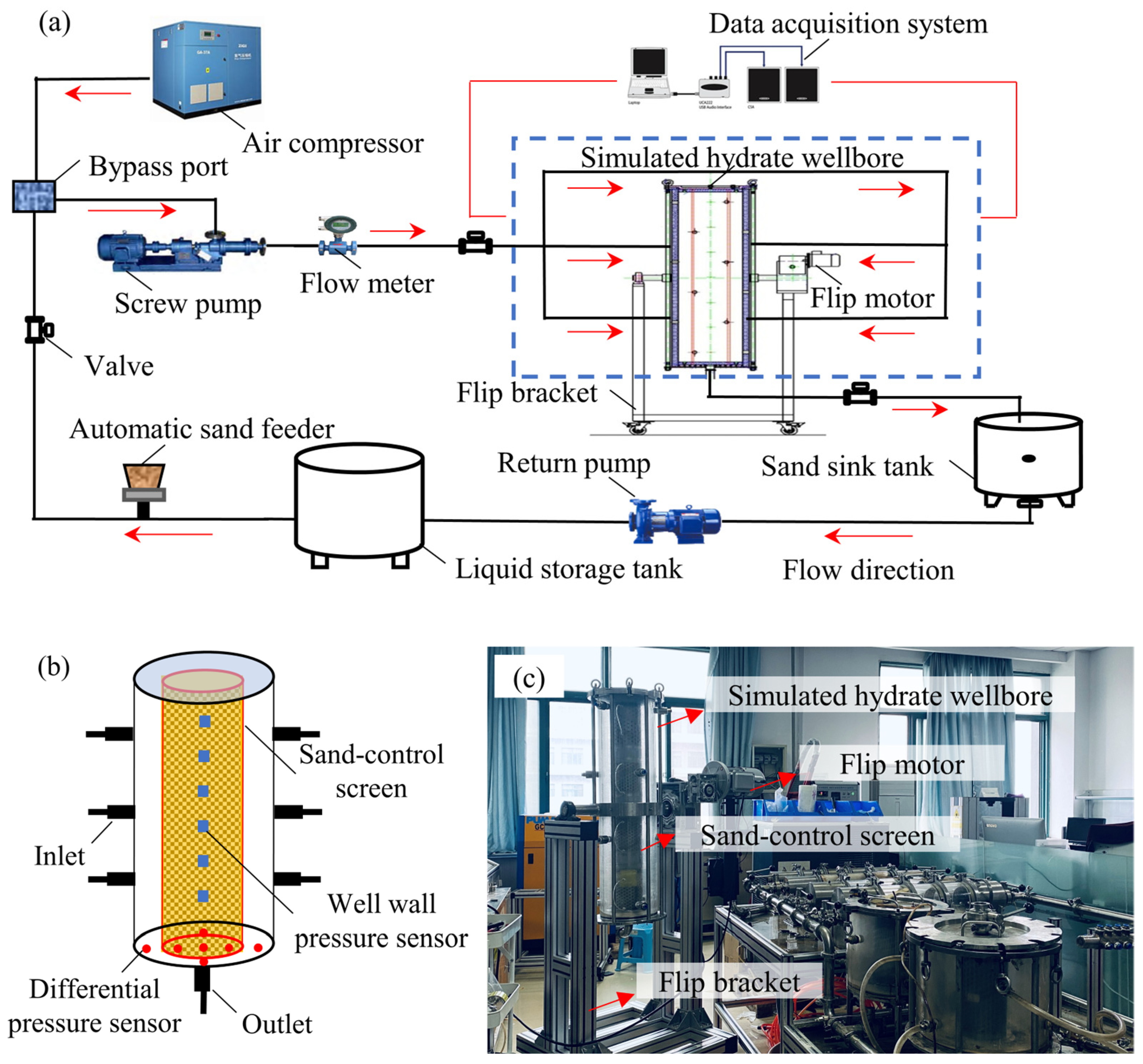
The marine hydrate well bottom inflow simulation device in this study is built to simulate the gas–water–sand inflow process in the sand control section of the hydrate well, which mainly consists of a screw pump, flow meter, simulated hydrate wellbore, data acquisition system, sand sink tank, return pump, liquid storage tank, automatic sand filler, air compressor, and so on (Figure 4a,c). The simulated hydrate wellbore is the core component of the device with an inner diameter of 220 mm, an outer diameter of 260 mm, and a height of 1000 mm, and it can accommodate a sand control screen with an outer diameter of 90–200 mm and a length of 900–998 mm. Six inlets were staggered on the well wall, and the flow outlets were located at the bottom of the wellbore. Six pressure sensors were equally spaced on the well wall to measure the pressure at different locations in the annulus, and four pairs of differential pressure sensors were evenly distributed at the bottom of the well to measure the differential pressure inside and outside the sand control screen (Figure 4b). The sand control screen was placed in the middle of the wellbore, and the angle of deviation of the wellbore can be adjusted in the range of 0–180° by adjusting the flip motor. The automatic sand filler realizes the automatic addition of formation sand to the pipeline and can precisely control the rate of sand addition. In addition, the data acquisition system can automatically collect flow, pressure, and differential pressure data during the experiment to calculate and analyze the screen permeability changes during the screen plug.
The NGH reservoir in the Shenhu area of the South China Sea is characterized by shallow burial and high mud content, and it belongs to a muddy silt sand hydrate reservoir with a mud content of 20–36% and a median grain size of 8–40 μm of which montmorillonite content is about 38%, illite content is about 32%, and kaolinite content is about 30% [11,18].
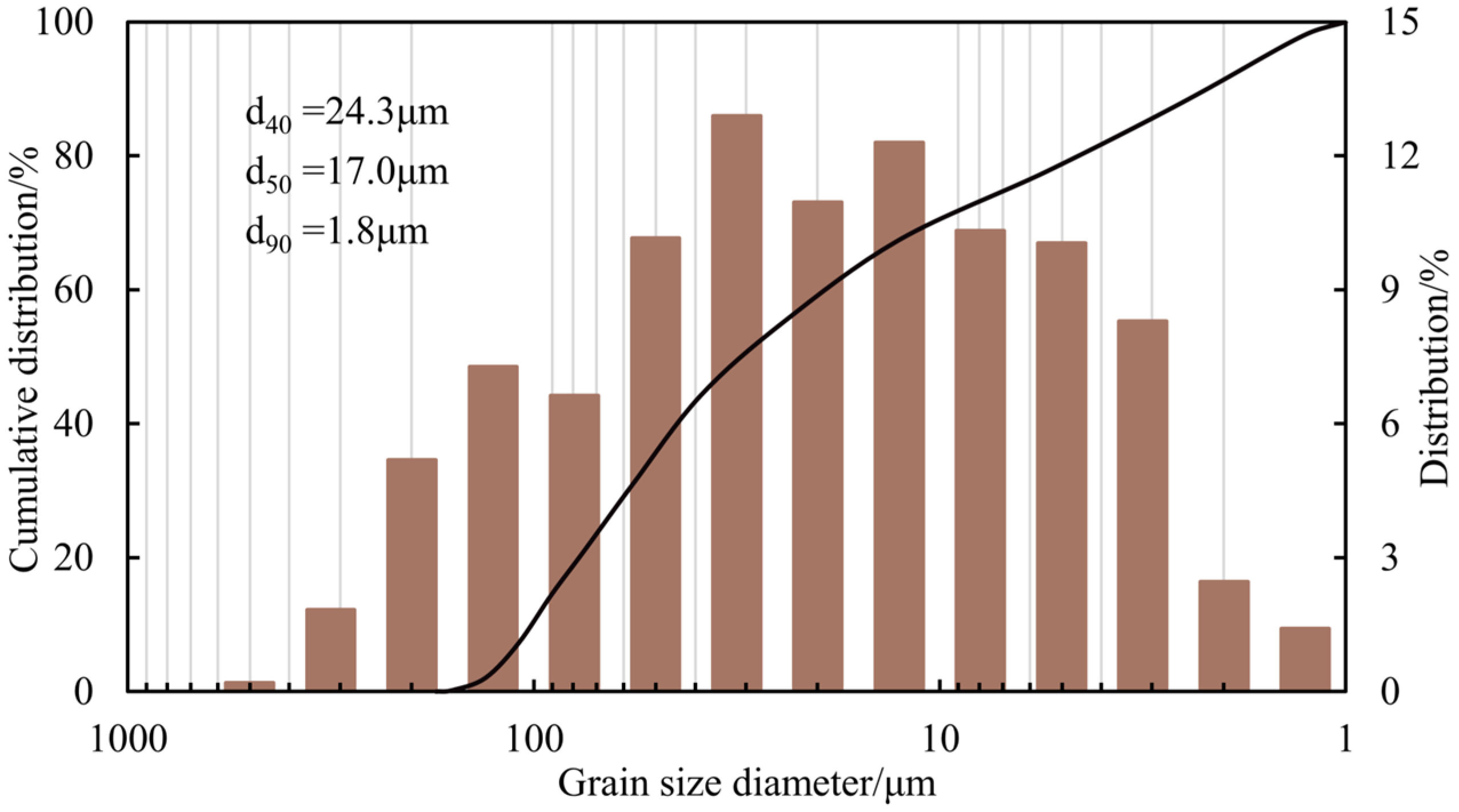
According to the characteristics of the formation sand of the NGH reservoir in the Shenhu area of the South China Sea, the sand with a median grain size of 17 μm and 20% mud content is compounded with quartz sand, montmorillonite, illite, and kaolinite (Figure 5). Figure 6 shows the grain size distribution curve of the compound formation sand. In addition, to simulate the GP sand control completion, the gravel used is 40–70 mesh conventional ceramsite.
The experimental flow rates of water and gas were calculated by using the dynamic similarity criterion to simulate the production conditions of the hydrate production test. Based on the first hydrate production test in the Shenhu area of the South China Sea, the experimental water flow rate was converted by the flow rate equivalence method. According to the gas–water ratio (GWR) and gas production at different moments of the production process, the experimental water flow rate was converted to 0.12–1.34 m3/h. To cover the actual production conditions, the experimental flow rate of water was set to 1.5 m3/h, which is higher than the converted flow rate of water. The GWR under reservoir conditions was converted by the gas volume coefficient based on experimental temperature and pressure conditions and hydrate reservoir temperature and pressure conditions. The experimental GWR ranges between 0.1 and 1.5 m3/m3, converted from the actual production GWR of hydrate wells. Therefore, the GWR in the basic experiment was set to 0.67 m3/m3. Another three GWRs of 0, 0.13, and 0.4 m3/m3 were set to research the effect of hydrate well production on the inflow pattern of gas–water–sand. In addition, the volumetric concentration of sand production (VCSP) or sand production rate in the NGH reservoir in the Shenhu area of the South China Sea is generally in the range of 0.05–1%. Therefore, four VCSPs (0.2%, 0.3%, 0.4%, and 0.5%) were set in this study to research the effect of the VCSP on the gas–water–sand inflow pattern, of which the basic experimental VCSP was 0.3%. All the experimental parameters of different sand control completion are summarized in Table 1.

3.2. Procedure and Methods

During the production of marine hydrate wells, hydrate may be reformatted in the hydrate reservoir near the wellbore and enter the wellbore along with the formation sand under the carrying of natural gas and water. However, the method of inhibitor or hot brine injection is generally used in the test production process to avoid hydrate reformation and prevent hydrate from plugging the sand control screen. Therefore, it is reasonable to disregard the hydrate dissociation and reformation process in this experiment and only simulate the inflow of gas–water–sand in the sand control section of the hydrate well. The experimental procedures include the following steps:
(1)
Put the screen into the simulated wellbore and pack the gravel into the annular between the screen and casing, connect the experimental device, and check the air tightness of the device.
(2)
Add the compound formation sand to the automatic sand filler, and fill the liquid storage tank with water.
(3)
Open the screw pump to pump water into the pipeline, and check the sealing of the device.
(4)
Set the target water and gas flow rate, adjust the VCSP, realize the mixing of gas, water, and sand through the gas–water mixer, turn on the screw pump, and return the pump to start the experiment.
(5)
Collect the flow and pressure data in real time through the data acquisition system to calculate the permeability of the screen and gravel packing layer, record the height of the gas–water interface in the wellbore annular by a camera, and collect and measure the volume of the sand deposited in the annulus at the end of the experiment.
The flow pattern of gas–water–sand in the annulus of the sand control section of marine hydrate wells mainly includes the transition law of gas–water interface height, the deposition law of formation sand, and the changes in the structure of the gravel packing layer. To analyze the dynamic transition law of the gas–water interface, the decrease and rising rate of the gas–water interface height were proposed for characterization (Equations (1) and (2)). Considering the influence of the size of the wellbore and the screen on the dynamic change law of the gas–water interface in the annulus of the screen and casing, the gas–water interface height firstly performs a dimensionless (the ratio of the gas–water interface height to the annulus diameter) to make the experimentally obtained results universal. And then calculate the dimensionless gas–water interface height variation rate. In addition, a deposition volume ratio was proposed for the characterization to analyze the deposition pattern of formation sand in the annulus of the sand control well section (Equation (3)).
V D = H A H B D A T B
where VD is the falling rate of the gas–water interface height, s−1; HA is the initial gas–water interface height in the annulus, m; HB is the lowest gas–water interface height in the annulus, m; DA is the size of the annulus between screen and casing, m; and TB is the time when the height of the gas–water interface in the annulus reaches its lowest position, s.
V U = H C H B D A ( T C T B )
where VU is the rising rate of the gas–water interface height, s−1; HC is the highest gas–water interface height in the annulus, m; and TC is the time when the height of the gas–water interface in the annulus reaches its maximum position, s.
R SV = V 1 V 0
where RSV is the deposition volume ratio, dimensionless; V1 is the total volume of the formation sand added during the experiment, ml; and V0 is the volume of the formation sand deposited in the annulus of the wellbore after the experiment, ml.
The permeability was calculated by Darcy’s formula using pressure and flow rate data to analyze the plug situation of the screen and gravel packing layer after the experiments. To maintain steady flow conditions to maintain the accuracy of the above parameter calculations, constant water and gas flow rates were maintained during the experiments through the use of variable frequency pumps and gas flow controllers. Because of the interference of electrical and magnetic signals, there are some slight fluctuations in both liquid and gas flow rates, but, overall, they are stable. The steady flow conditions ensure the accuracy of the above parameter calculations.

4. Results

4.1. Inflow Pattern in SAS Completion

4.1.1. Situation of Vertical SAS Well

(1)
Gas–water interface
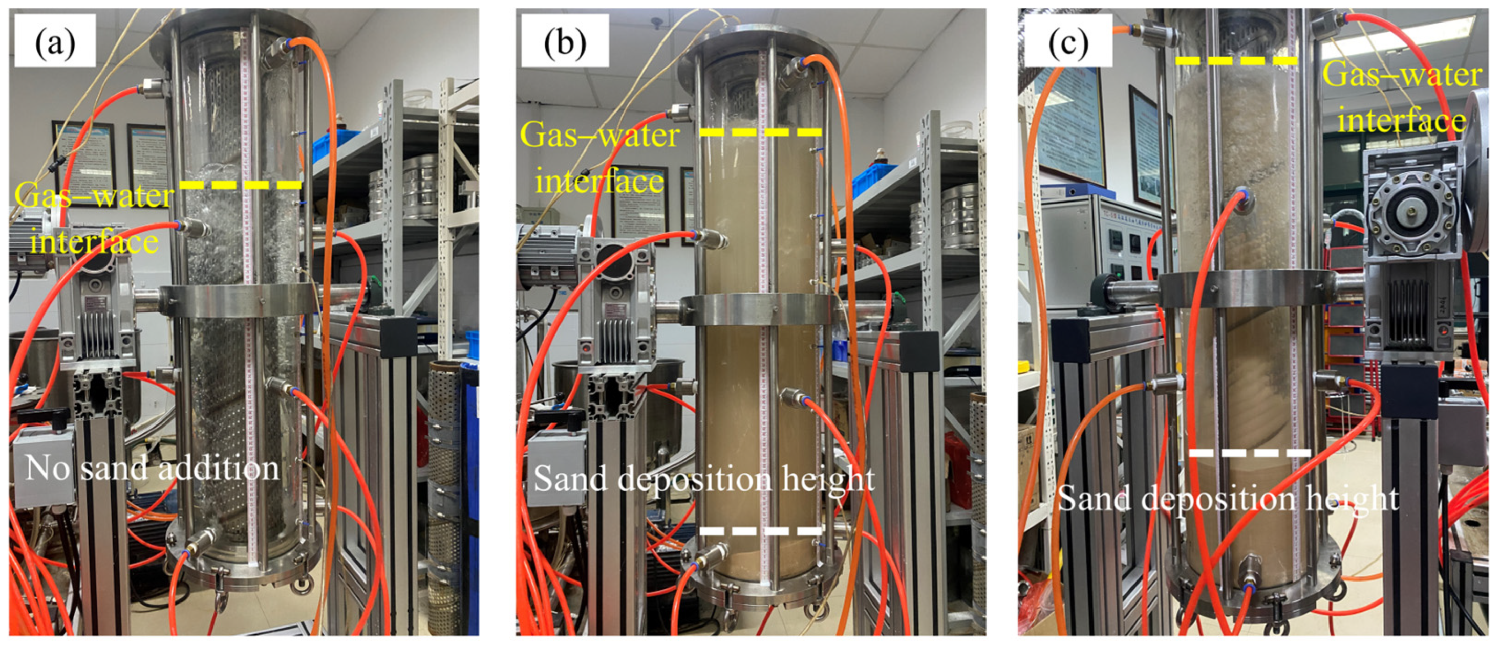
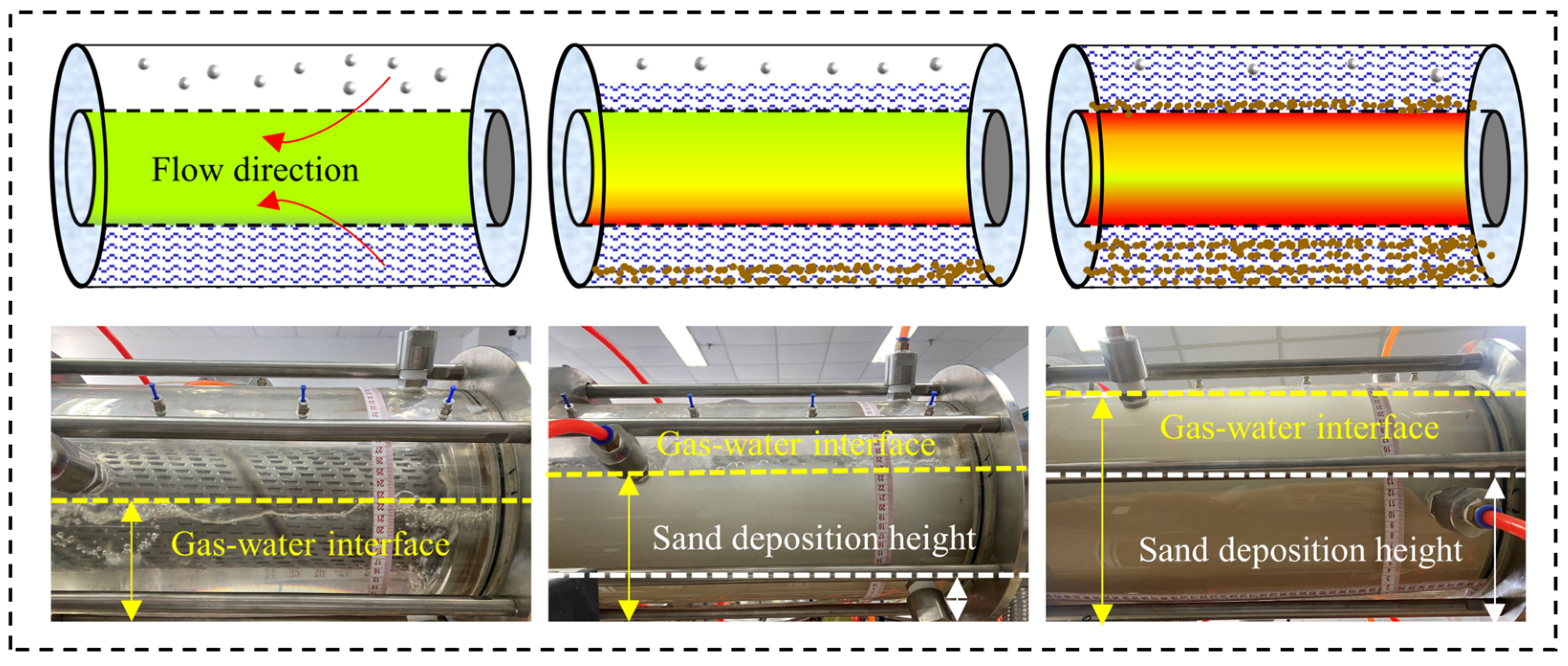
Figure 7 shows that gas–water stratification occurs in the annulus of the screen and casing in the NGH vertical well with SAS completion when the formation sand is carried by the water and gas into the wellbore and flows in the sand control well section. The gas is in the upper layer, and the water and sand are in the lower layer, with the water being the main sand-carrying phase. Various regions of the screen were gradually plugged as the experiment progressed, resulting in a dynamic transition in the height of the gas–water interface and the sand deposition in the bottom of the well.
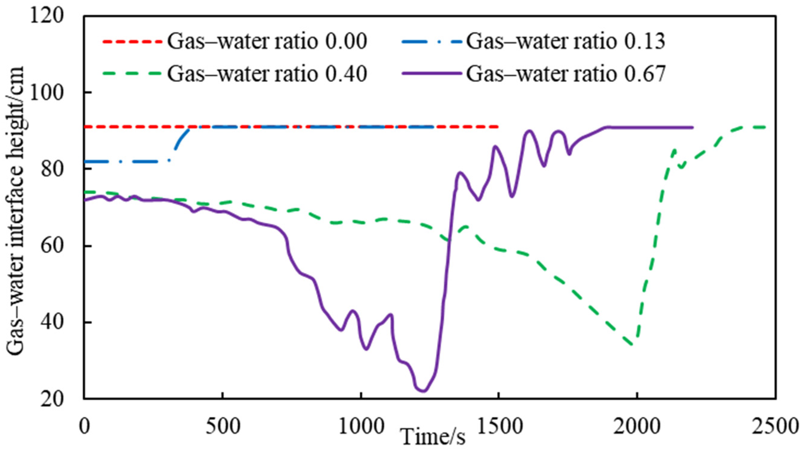
Interestingly, experimental results show that the height of the gas–water interface decreases first and then increases with the screen plugging in some experimental conditions. Figure 8 shows that the variation law of the gas–water interface is significantly affected by the GWR. The annulus only contains gas and liquid without a sand addition at the beginning of the experiment. The resistance of the water and gas phase through the screen is equal, resulting in a dynamic balance of the gas–water interface and a constant initial height of the gas–water interface. A larger GWR strengthens the compression effect of the gas on the liquid, resulting in a lower initial height of the gas–water interface.
However, the balance state of the gas–water interface is destroyed because of gradual screen plugging when adding formation sand into the well, which leads to variation in gas and liquid flow resistance. Figure 8 shows that the height of the gas–water interface decreases and then increases when there is a high GWR. The rise and fall of the gas–water interface depends on the magnitude of the relative resistance of gas and water to passing through the screen. The gas flow resistance exceeds the water flow resistance with the plugging of the screen, requiring a larger flow space for gas flow. This action results in a fall of the gas–water interface, which weakens the degree of screen plugging and reduces gas flow resistance. However, the water requires more space to flow if the gas flow resistance is lower than that of water, resulting in a rise in the gas–water interface in the wellbore annulus. The compression of the gas in the water is weak when the GWR is low, resulting in a high initial gas–water interface. The water flow resistance was greater than the gas flow resistance with the plugging of the screen. The gas–water interface gradually rises, and there is no fall phenomenon of the gas–water interface during the experiment.
(2)
Influencing factors
During NGH reservoir development, factors such as the VCSP in the NGH reservoir, production conditions (GWR), and the NGH well type significantly affect the degree of screen plugging, which in turn affects the inflow law of gas–water–sand in the sand control section of NGH well.
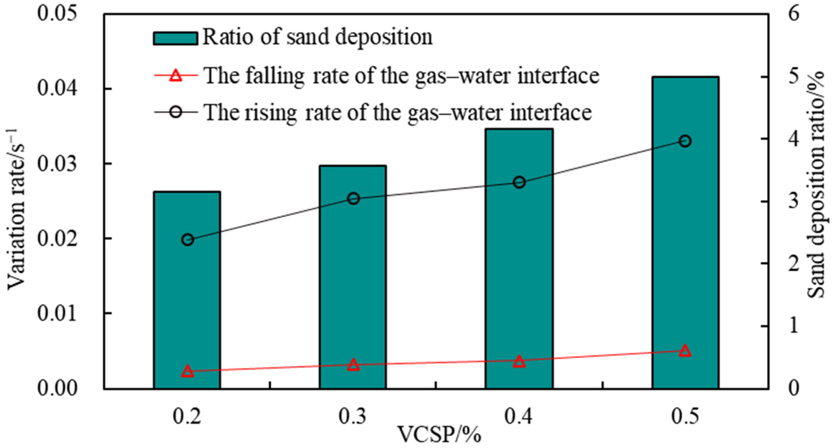
Figure 9 shows that the falling and rising rates of the gas–water interface are positively correlated with the VCSP, which both increase gradually with the increase in the VCSP. The quantity of formation sand entering the wellbore also increases as the VCSP increases, which increases the probability of formation sand deposition on the screen surface and may easily lead to screen plugging.
In the falling stage of the gas–water interface, the flow resistance of gas through the screen is greater than that of water through the screen. The high VCSP exacerbates the screen plugging. Consequently, an increase in the VCSP will result in an increase in the gas flow resistance through the screen, which will lead to a corresponding increase in the rate of gas–water interface decrease. In the rising stage of the gas–water interface, the flow resistance of water through the screen is larger than that of gas. The higher the VCSP is, the more space is needed for water to flow, which leads to a larger rate of gas–water interface increase.
In addition, Figure 9 also shows that higher VCSP hydrate reservoirs can exacerbate the deposition of formation sand in the annulus of the screen and casing in the hydrate well. Sand burial may occur in a hydrate well under prolonged production conditions, severely reducing gas production. Therefore, while ensuring that the screen has better sand control performance, the appropriate relaxation of sand control precision should be considered to avoid a sand burial phenomenon when designing the sand prevention parameters for hydrate reservoirs with a high VCSP.
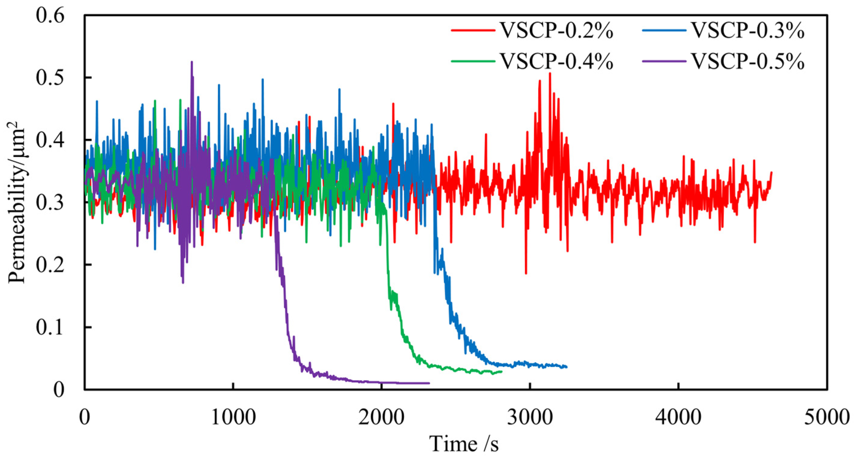
The area and degree of screen plugging change with the variation in the gas–water interface. Figure 10 shows the relationship between the VCSP and screen permeability during gas–water–sand inflow. The screen permeability begins to decline earlier as the VCSP increases. The higher the VCSP, the more formation sand enters the wellbore at the same time, which leads to the easier plugging of the screen and the easier loss of screen permeability. Therefore, the VCSP is also a factor to be considered in the design of sand control parameters for hydrate reservoirs because the VCSP significantly affects the sand control effect of the screen. The accuracy of sand control should be appropriately reduced so that the screen can maintain high permeability performance for hydrate reservoirs with high sand concentration, which contributes to improving the hydrate well production.
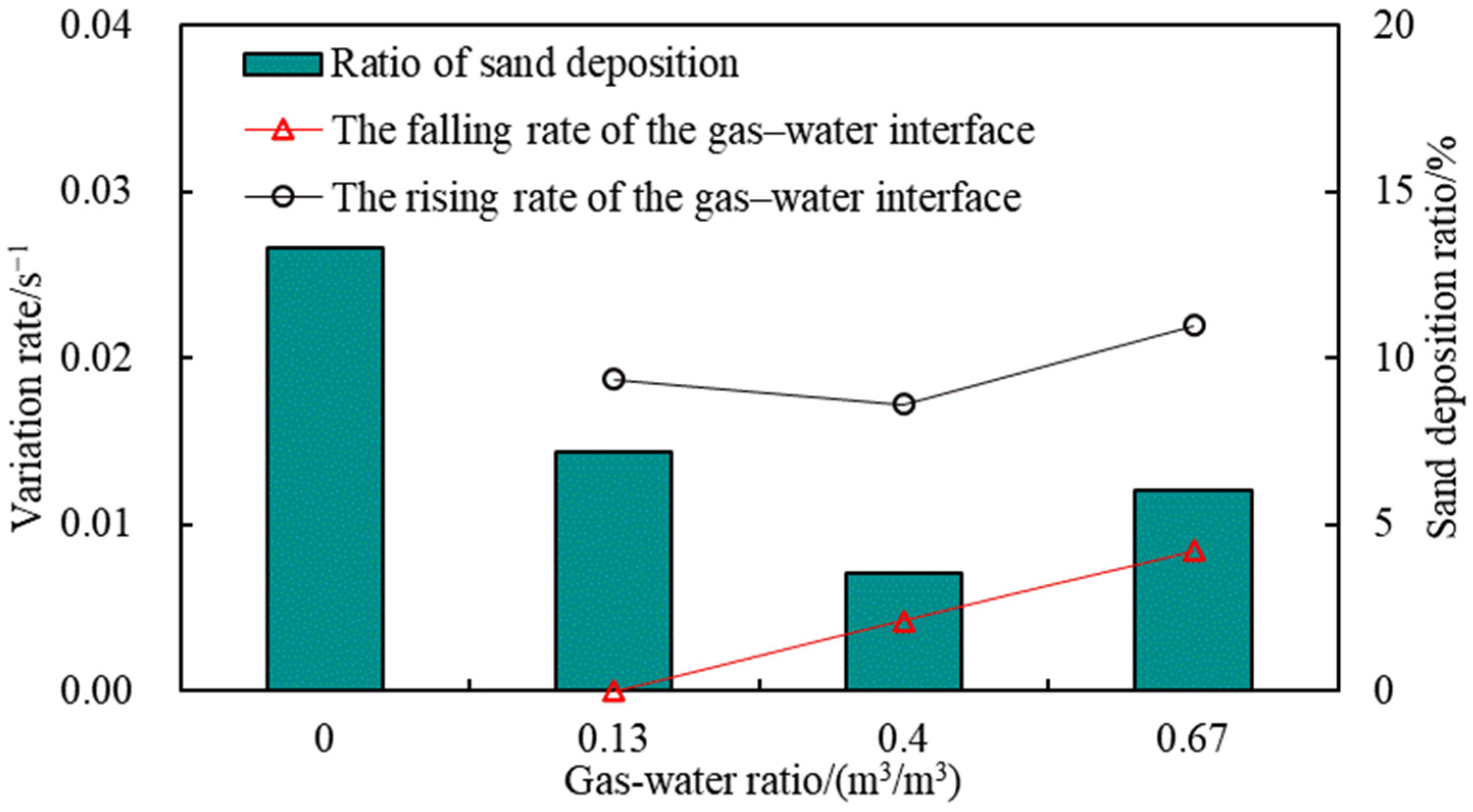
When the gas–water–sand flows in the wellbore, the perturbing effect of the gas affects the variation in the gas–water interface and the formation sand deposition. Figure 11 shows the relationship between the GWR and the variation rate of the gas–water interface and the formation sand deposition. There is no gas–water stratification in the absence of gas injection into the wellbore. The gas-to-liquid compression is enhanced as the GWR increases, resulting in a larger falling rate of gas–water interface height. However, in the rising stage of gas–water interface height, the rising rate of the gas–water interface decreases first and then increases with the increase in GWR. The gas perturbation can lift part of the screen plugging when in a low GWR, reduce the sand deposition rate, and reduce the flow resistance of water through the screen, thus reducing the rising rate of the gas–water interface height. However, the gas–water interface rising rate will not always decrease with the increase in GWR. When the GWR is large, the gas carrying the sand effect gradually enhanced, resulting in strengthening the screen plugging degree and increasing the sand deposition rate and water flow resistance through the screen, which leads to increasing the gas–water interface rising rate.
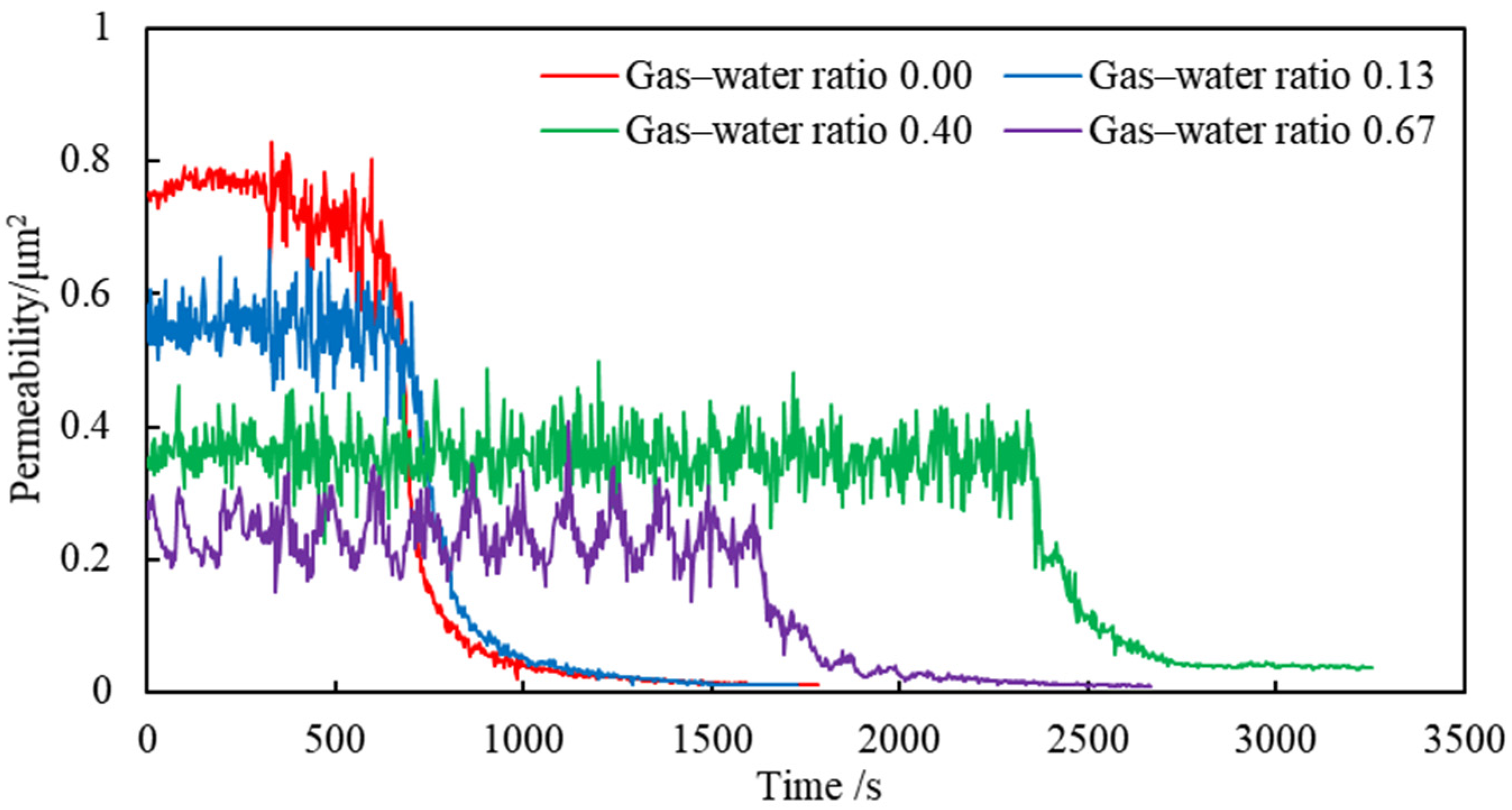
A reasonable GWR can help to reduce screen plugging, and Figure 12 illustrates the relationship between the GWR and screen permeability. When the fluid entering the wellbore contains only formation sand and water, the screen is the first to plug, resulting in a permeability decrease in the screen. It takes longer for the screen permeability to decrease as the gas is injected, indicating that gas injection does have the effect of unplugging the screen. However, it is not the case that a higher GWR necessarily results in a more effective unplugging effect. Because, under the conditions of a GWR of 0.40 and 0.67, the time for permeability to decrease is 2450 s and 1600 s, respectively. Compared with the two conditions, under the condition of the GWR of 0.67, the screen is more likely to be plugged, resulting in an earlier decrease in permeability. When the ratio of gas to water reaches a certain threshold, the sand-carrying effect of the gas gradually intensifies, resulting in a gradual accumulation of formation sand on the surface of the screen, which leads to increased screen plugging and a greater loss of screen permeability. Therefore, controlling a reasonable hydrate production can help to improve the permeability performance of the screen tube, thereby increasing the hydrate production in actual NGH production tests.
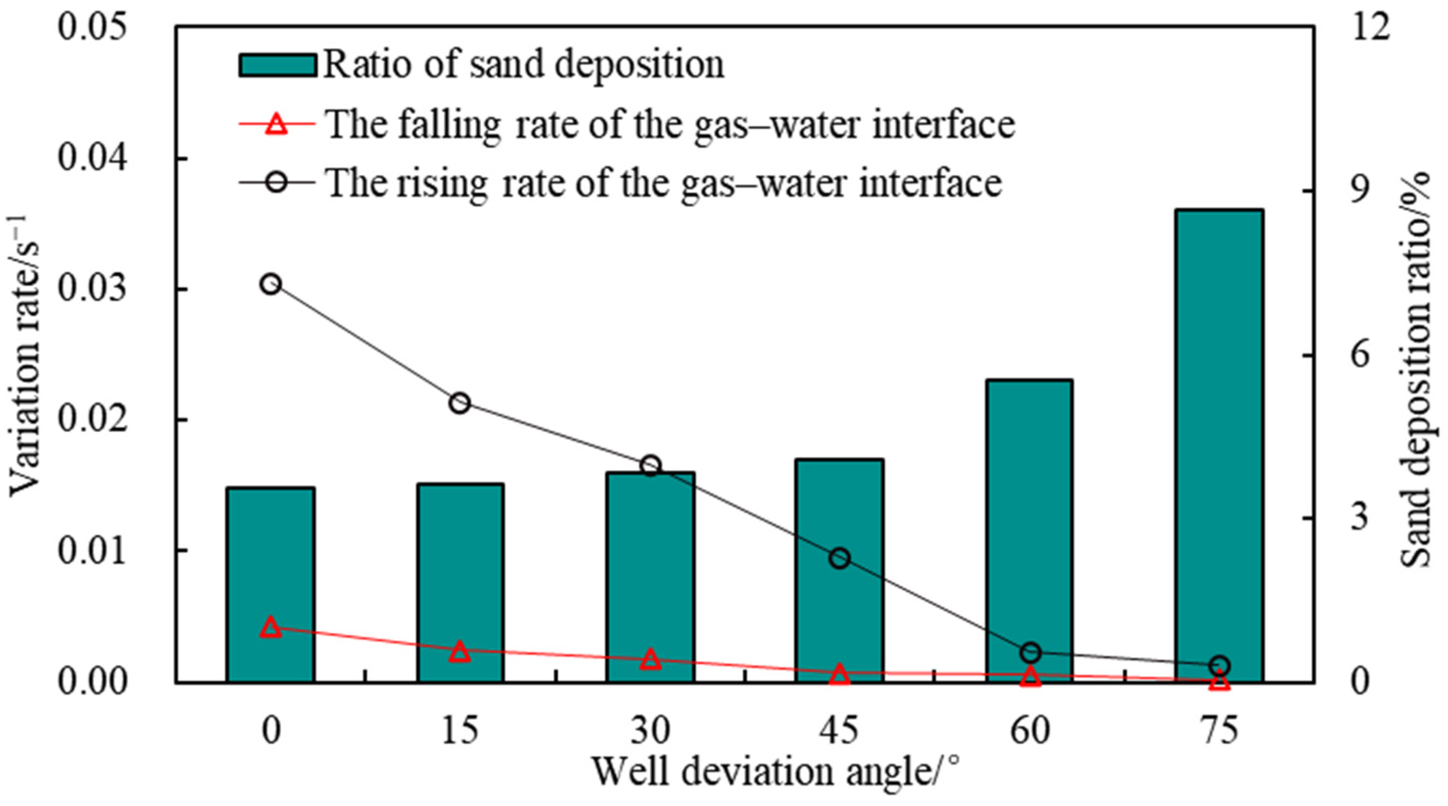
The pattern of gas–water–sand inflow varies significantly in different types of hydrate wells. Figure 13 shows the relationship between the deviation angle and variation rate of the gas–water interface and sand deposition ratio. Six deviation angles representing six types of hydrate wells were studied in this article. Both the gas–water interface rising rate and the gas–water interface falling rate decrease with the increase in the deviation angle, and the sand deposition rate increases with the rise in the deviation angle. As for the vertical hydrate well (deviation angle 0°), the screens located in the water phase are uniformly plugged by the formation sand. When the deviation angle increases, the formation sand is easily deposited at the bottom of the wellbore under the influence of gravity, resulting in the lower region of the screen maintaining a higher permeability and the overall degree of plugging of the screen being weakened. Therefore, the flow resistance of water through the screen decreases with the increase in the deviation angle in the rising stage of the gas–water interface, resulting in the rising rate of the gas–water interface decreasing with the rise in the deviation angle.
The difference in the degree of screen plugging when gas–water–sand inflows in different types of hydrate wells is shown in Figure 14. The screen in a vertical well (at a 30° deviation angle) has the earliest decrease in permeability, indicating that the screen is most prone to plugging when the hydrate well is vertical. Theoretically, an increase in the deviation angle will cause the formation sand to be deposited at the bottom of the wellbore under the influence of gravity, reducing the degree of screen plugging. The larger the deviation angle, the weaker the degree of screen plugging. However, this is not the case in the experimental results. When the deviation angle is less than 30°, the decrease time of screen permeability gradually becomes longer with the increase in the deviation angle. However, the time becomes shorter with the increase in the deviation angle when the deviation angle is greater than 30°. This result suggests that there is a critical deviation angle in the range of 30–45°, which can weaken the degree of screen plugging, but the specific deviation angle needs further research.

4.1.2. Gas-Water–Sand Inflow in Horizontal SAS Well

For the horizontal NGH well with SAS completion, the same gas–water stratification phenomenon occurs when the gas–water–sand inflow enters the wellbore, with the gas located in the upper space of the wellbore, the liquid in the lower space of the wellbore, and the formation sand distributed in the water (Figure 15). During the flow of gas and water–sand in the wellbore, the lower part of the screen tube is first blocked by formation sand, which then leads to a gradual increase in the gas–water interface.
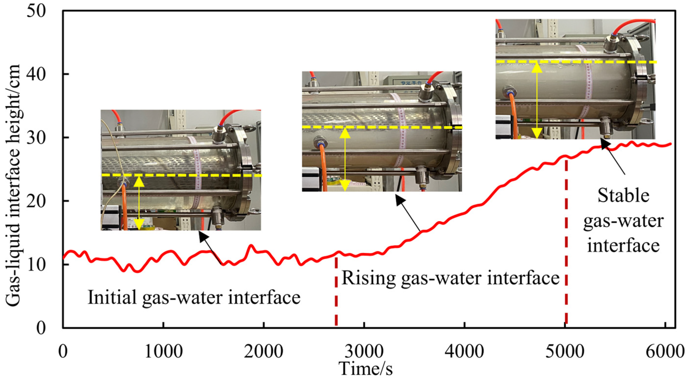
For the horizontal and vertical NGH wells with SAS completion, although gas–water stratification occurs in both wells, the height of the gas–water interface in the wellbore shows a different pattern of variation. Figure 16 shows the varying law of the gas–water interface in a horizontal well. In horizontal wells with SAS completion, with the plugging of the screen, the height of the gas–water interface gradually rises until the liquid fills the annulus of the wellbore, and the height of the gas–water interface does not show any decreasing phenomenon. Because of the influence of gravity, the formation sand is not easy to be deposited on the surface of the lower part of the screen, which leads to the screen located in the water part of the screen being not easily clogged. Throughout the experiment, the liquid flow resistance is always greater than the gas flow resistance, resulting in a gradual increase in the height of the gas–water interface.
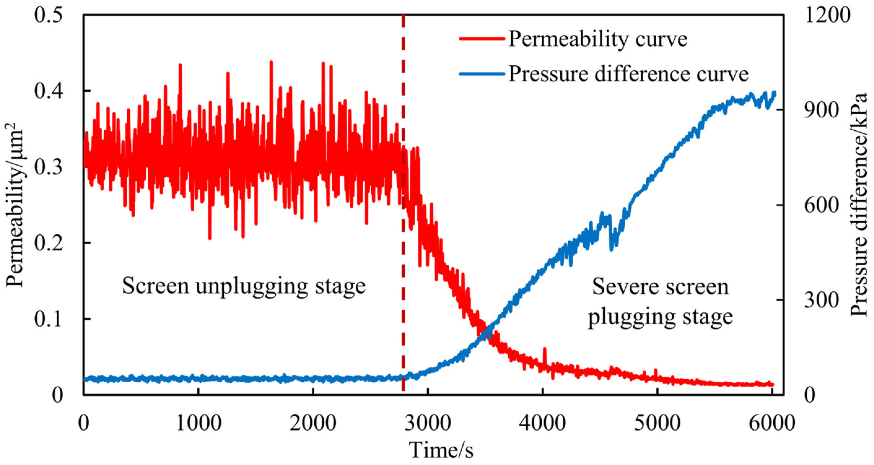
To further investigate the correlation between the screen plugging process and the gas–water interface change process, calculate and analyze the change rule of the screen permeability in the experimental process (Figure 17). The initial permeability of the screen is 0.33 D. When the experiment reaches 2817 s, the blockage of the screen begins to intensify, the pressure difference inside and outside the screen begins to increase, and the permeability begins to decrease. The phenomenon of phased changes in pressure and screen permeability was similarly demonstrated in other studies [30,48]. Figure 16 and Figure 17 also show that, in the early stage of the experiment (0–2817 s), the height of the gas–water interface remained stable when the screen tube was not blocked. When the experiment progressed to 2817 s, the height of the gas–water interface began to rise after the screen tube was blocked, and the liquid eventually filled the annulus. The height of the gas–water interface reached its maximum value, and the final permeability of the screen tube was 0.013 D.

4.1.3. Mechanism of Gas–Water Interface Transition

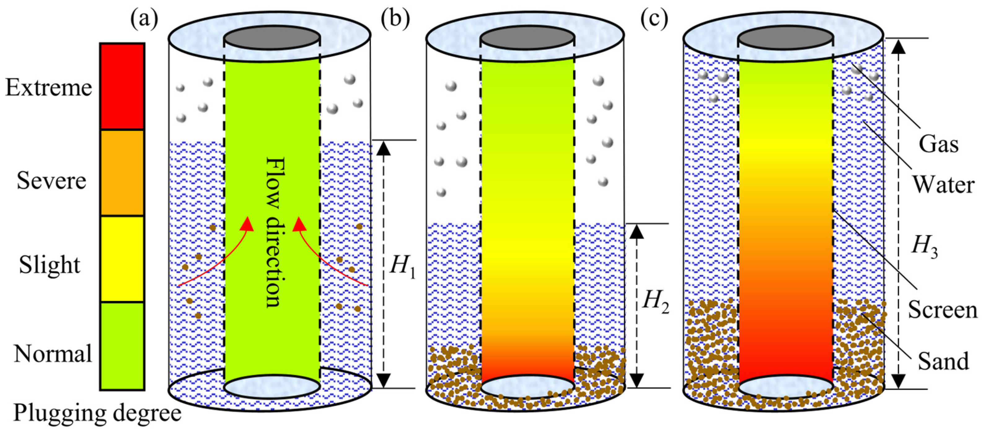
When no sand is added at the beginning of the experiment, the height of the gas–water interface in the annulus remains unchanged. The relative resistance of liquid and gas passing through the screen is equal, and the gas–water interface is in dynamic equilibrium (Figure 18a,d). When the relative resistance of gas flow is greater than that of liquid flow, gas flow requires more flow space. The gas in the upper space of the wellbore annulus compresses the liquid, causing the height of the gas–water interface to begin to decrease (Figure 18b,e). When the relative resistance of gas flow is smaller than that of liquid flow, liquid flow requires a larger flow space, and the height of the gas–water interface in the wellbore annulus begins to rise (Figure 18c,f). When the GWR is low, the compression of the gas in the liquid is weak, resulting in a high initial gas–water interface. In the process of screen plugging, the liquid flow resistance has been greater than the gas flow resistance. The gas–water interface gradually increases as the experiment progresses, and there is no phenomenon of the gas–water interface decreasing during the experiment.
In horizontal wells with SAS completion, with the plugging of the screen, the height of the gas–water interface gradually rises until the liquid fills the annulus of the wellbore, and the height of the gas–water interface does not show any decreasing phenomenon (Figure 19). Because of the influence of gravity, the formation sand is not easily deposited on the surface of the lower part of the screen, which leads to the screen located in the water part of the screen being not easily clogged. Throughout the experiment, the liquid flow resistance is always greater than the gas flow resistance, resulting in a gradual increase in the height of the gas–water interface.

4.2. Inflow Pattern Analysis of GP Well

4.2.1. Uniform Inflow Pattern

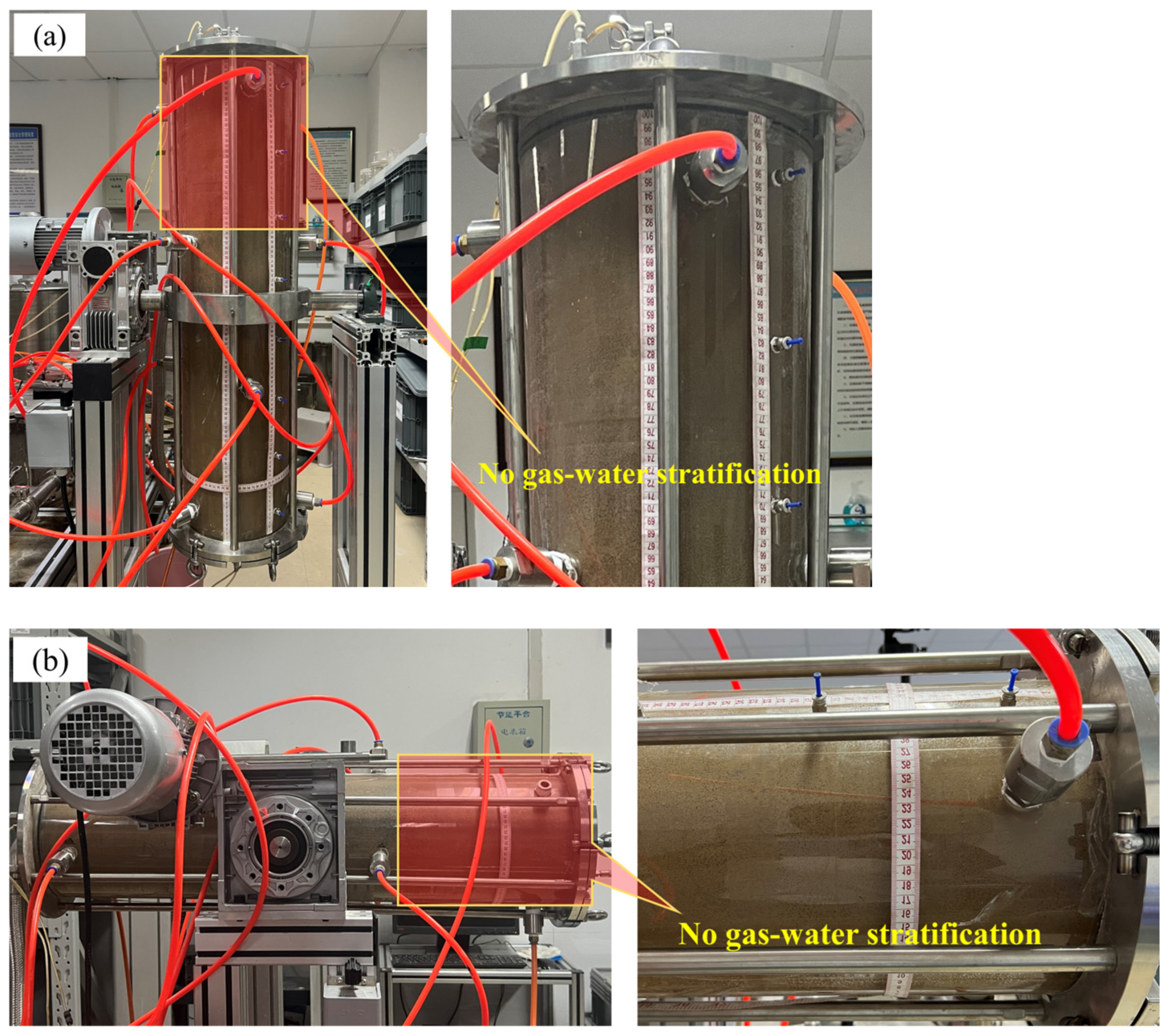
The screen and casing annulus of the hydrate well with GP completion are packed with 40–70 mesh conventional ceramsite, resulting in a different gas–water–sand inflow pattern compared with SAS completion. Figure 20 shows the gas–water–sand inflow pattern in hydrate wells with GP completion. The gas–water–sand inflows uniformly both in the vertical and horizontal wells, and there is no gas–water stratification flow phenomenon.
Because of the 40–70 mesh conventional ceramsite filling in the wellbore, the gas–water–sand inflow pattern in the gravel layer was not photographed. Therefore, a schematic diagram was drawn to visualize the gas–water–sand inflow pattern in the NGH well with GP completion, as shown in Figure 21. Compared with the SAS completion, the gravels in the GP completion form a porous 3D structure, which reduces the flow area of gas–water–sand and leads to the rapid filling of water into the pores between the gravels, and the gas–water–sand flows uniformly in the gravel layer without gas–water stratification. When the gas–water–sand flows uniformly in the gravel layer, the gas is mainly in the form of bubbles in the gravel layer, and the fine sand gradually enters the inside of the screen through the gravel layer, and the coarse sand gradually invades and remains in the inside of the gravel layer.

4.2.2. Erosion Failure of Packed Gravel

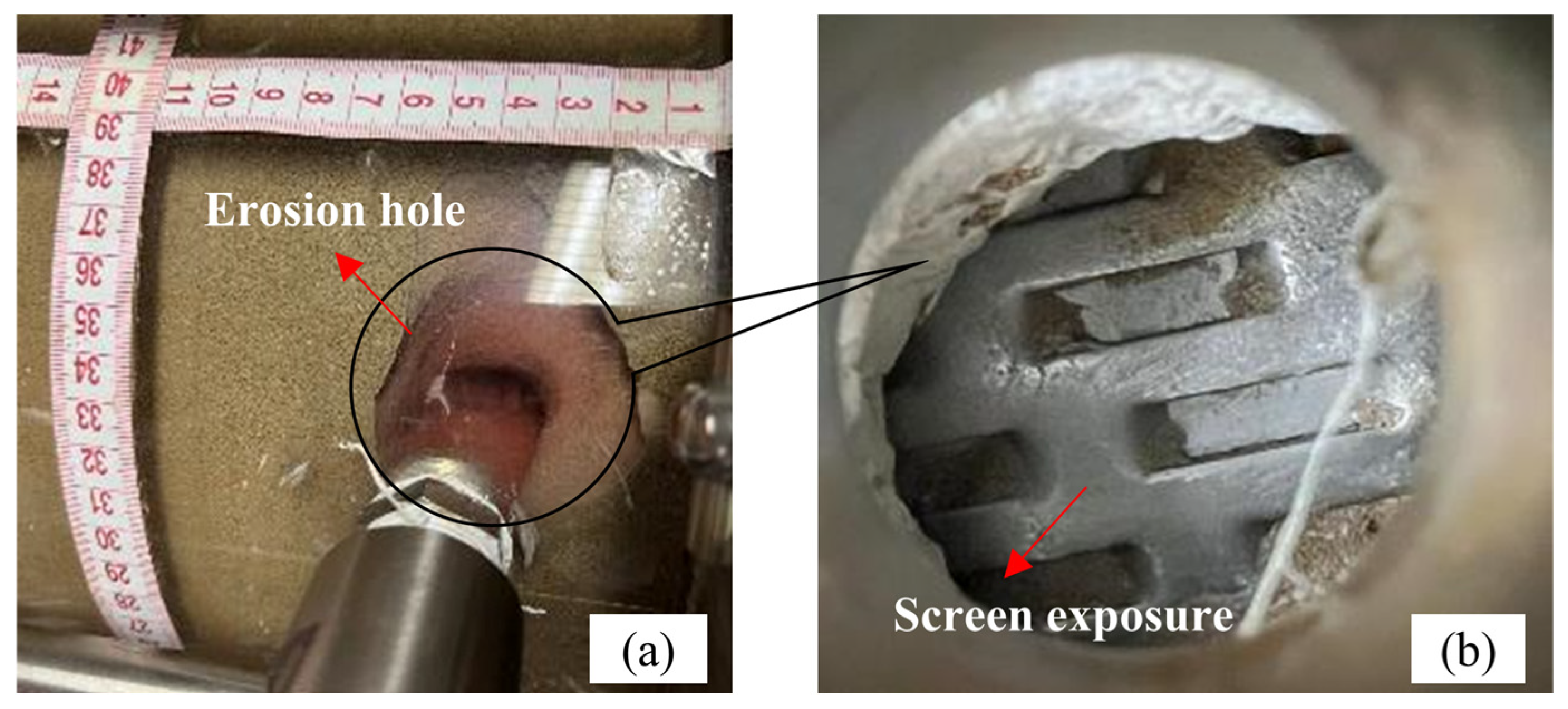
Although gas–water stratification did not occur in the GP completion, it is interesting to note that the gravel layer structure was progressively damaged, and an erosion hole was formed as the gas–water–sand flowed in the gravel layer (Figure 22a).
The formation sand is controlled on the outside of the gravel layer at the location of high gravel packing degree. However, the gravel layer is destabilized and reorganized by the impact of gas and water, and a hole is formed at the location of low gravel packing degree. Once an erosion hole is formed in a gravel layer, the gravel packing degree near the erosion hole decreases sharply. The volume (depth) of the erosion hole gradually increases under the continuous impact of air and water, weakening the sand control effect of the gravel layer. With the expansion of the erosion hole, the deficit volume of the gravel layer gradually increases, which gradually leads to the exposure of the screen inside the gravel layer (Figure 22b). Then, the gas–water–sand passes through the screen directly, and the sand control performance of the gravel layer decreases sharply.
The GWR significantly affects the formation of erosion holes in the gravel layer. Three GWRs (0.9, 1.8 and 2.7 m3/m3) were researched in this article. Figure 23 shows the relationship between the GWR and erosion hole in the gravel layer. It can be observed that an increase in the GWR results in a corresponding increase in the non-uniform inflow velocity of the gas–water–sand, which enhances the impact on the gravel filling layer and results in a more serious gravel destabilization and larger formation of erosion holes.
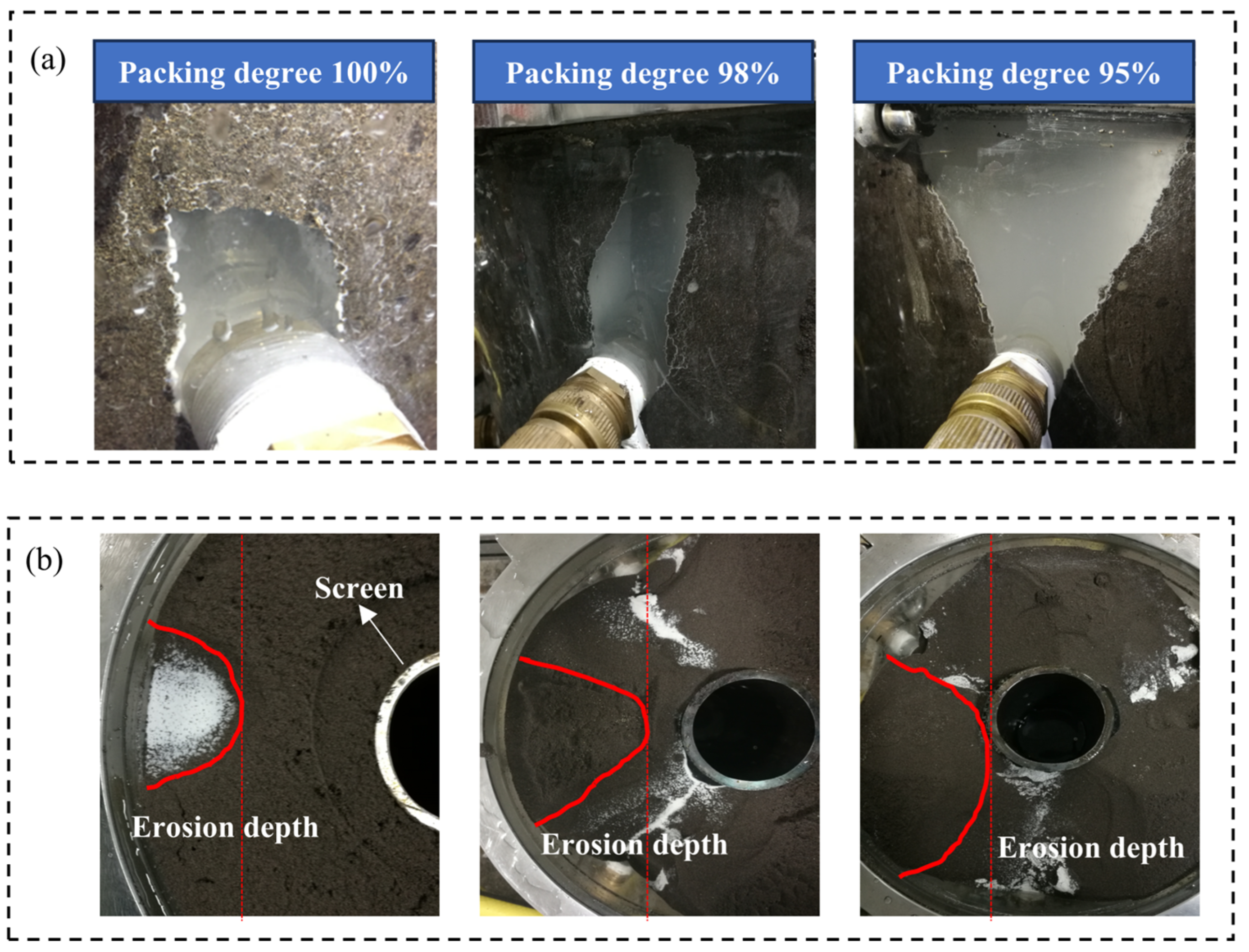
The phenomenon of erosion holes in the instability of gravel layers was also confirmed in the studies of some scholars. The effect of gravel packing degree on the stability of the gravel layer was studied. Figure 24 shows the relationship between the gravel packing degree and the shape and depth of the erosion hole in the gravel layer. When using 40–70 mesh conventional ceramsite for experiments, the results show that the formation of erosion holes in the gravel layer is inevitable, even in the case of 100% packing degree (Figure 24a). Figure 24b also shows that the erosion holes gradually expanded and even broke through the gravel layer to the outer wall of the screen with a decrease in the packing degree [40].
However, it is impossible to guarantee a 100% packing degree of gravel during the actual hydrate well development process. Furthermore, the presence of a high-speed inflow hotspot in the whole hydrate well will exacerbate the destabilization and damage of the gravel layer, which will lead to the sand control failure of the gravel layer. The screen should play a key role in controlling sand when the gravel layer fails. Therefore, when designing the GP completion, the sand control accuracy of the screen should be based on the principle that the screen directly controls the formation sand, rather than just supporting the gravel layer.

4.2.3. Plugging Performance

Figure 25 shows the variation in gravel layer permeability from unplugging to the destabilized state under different GWRs. When the gas–water–sand flows in the gravel layer, at the beginning of the experiment, the fine sand passes through the gravel layer directly (Unplugging stage). The gravel layer was gradually plugged, resulting in a decrease in the permeability of the gravel layer with the continuous intrusion of formation sand in the gravel layer (Plugging stage). The resistance to the flow of gas and water through the gravel layer increases after the plugging of the gravel layer. The gravel is displaced to form an erosion under the impact of gas and water, resulting in a gradual increase in the permeability of the gravel layer (Erosion hole formation stage).
The permeability of gravel layers at different stages under different GWRs, the rate of permeability loss, and the rate of permeability recovery after the formation of the erosion hole are summarized in Table 2. Table 2 shows that the permeability of the gravel layer after plugging is higher with the increase in GWR. Because the gas has a certain unplugging effect, the formation sand that enters the inside of the gravel layer is easily discharged under the disturbing effect of the gas. Therefore, the lower the permeability loss rate of the gravel layer as the GWR increases. However, the impact of gas and water on the gravel layer is strengthened as the GWR increases. A high GWR accelerates the formation of erosion holes in the gravel layer and intensifies the degree of erosion damage, leading to an increase in the permeability of the gravel layer and a weakening of the sand control performance. As the GWR increases, the recovery rate of permeability of the gravel layer rises (Figure 26), while the sand control performance of the gravel layer declines.

4.3. Optimization of Completion

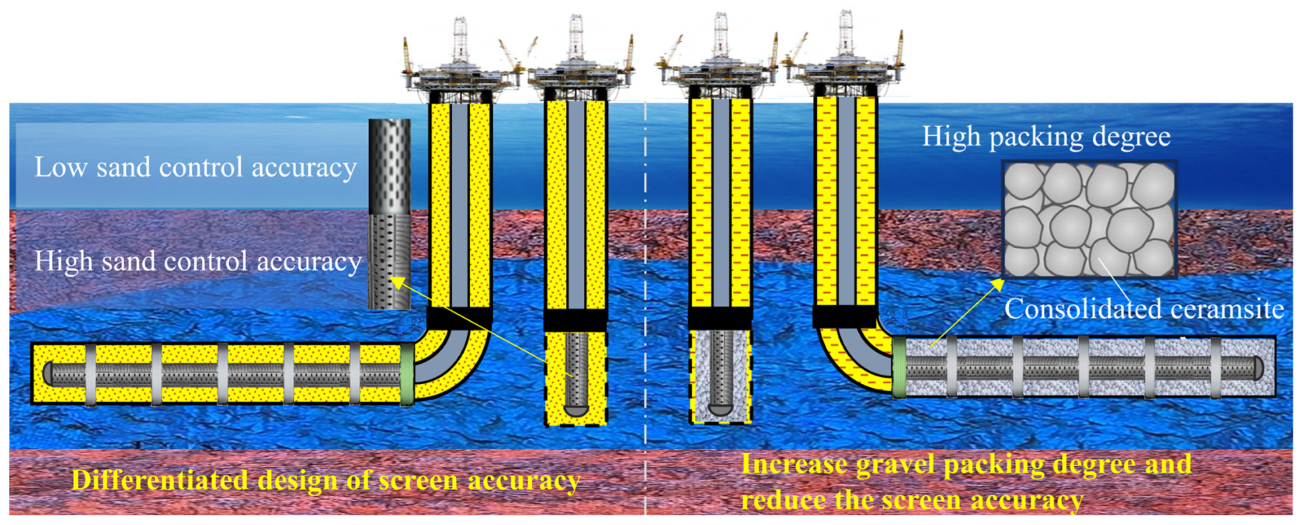
Under the long-term marine NGH production, the sand control performance of different sand control completions changes dynamically under the impact of gas–water–sand inflow, which limits the development and utilization of marine NGH energy. These findings above about the inflow pattern of gas–water–sand in the sand control section of marine hydrate wells with different completions provide good inspiration for optimizing the design of completions for different types of marine NGH wells. Figure 27 shows an optimization diagram of different sand control completion methods.
For vertical and horizontal wells with SAS completion, the gas–water stratification during the inflow of gas–water–sand in the wellbore leads to non-uniform plugging of the screen. After a long time of production of the hydrate well, the screen located in the water phase is plugged seriously, while the screen located in the gas phase maintains high permeability. However, the current SAS sand control completion for hydrate wells does not differentiate the sand control accuracy of the screen according to the difference in the plugging degree at different positions of the screen but adopts a unified sand control accuracy as a whole, which is costly and limits the increase in hydrate well production.
Therefore, for hydrate wells with SAS completion, it is recommended that the sand control screen is optimized to have two different sand control accuracies for the upper and lower parts of the screen, taking into account the non-uniform plugging phenomenon of the screen. The lower screen plays the role of sand control with high sand control accuracy. The upper screen is designed with a low sand control accuracy to enhance the gas conductivity, which contributes to improving the hydrate production.
Regarding the GP completion, the gravel layer destabilizes and forms an erosion hole at the high-speed inflow hotspots of the NGH reservoir, resulting in the exposure of the screen inside the gravel layer and the sand control failure of the gravel layer. Maintaining the stability of the gravel layer is beneficial to prolonging the validity of the GP completion. However, in the current hydrate production tests using GP sand control completion, to avoid high packing pressure from damaging the hydrate reservoir, lightweight ceramsite is used for gravel packing [49,50]. However, the low-density lightweight ceramsite will lead to a decrease in the gravel packing degree, which will sharply weaken the stability of the gravel packing layer.
Therefore, for hydrate wells with GP completion, the density of gravel should be increased as much as possible under the premise of ensuring the stability of the NGH reservoir. In addition, the coated ceramic with cementing effects can enhance the strength of the gravel layer to improve the stability of the gravel layer. Once the gravel layer is damaged, the screen inside the gravel layer will be the last sand control barrier of the GP completion. However, when designing the sand control accuracy of the screen in the GP completion, it is generally designed based on the ability to support gravel, and the sand control effect of the screen is not considered. The reasonable design of the sand control accuracy of the screen inside the gravel layer is conducive to prolonging the validity of the GP completion. Therefore, when designing the sand control accuracy of the screen, it is not only necessary to consider the supporting gravel, but also, more importantly, it should be considered that the screen can directly control the formation sand.

5. Discussion

The bottom of the marine NGH well is a complex three-phase fluid environment of gas, water, and sand. Complex fluids cause dynamic changes in different sand control completion systems. For SAS and GP sand control completion systems, the phenomena of uneven plugging of screens caused by gas–water stratified flow and the erosion failure of gravel layers caused by gas–water–sand impact observed in indoor experiments are objective. Because indoor physical experiments are affected by many factors such as experimental operators [51,52], signal interference, experimental time, and device scale, the laws of gas–water interface change, gravel layer instability may not be accurate, and the analysis metrics may have certain errors. Before the experiment, we conducted multiple test experiments to reduce the deviation caused by the signal interference and experimental device. During the experiment, we did not change the experimental operators to eliminate the deviation caused by the operators. In addition, outliers with large fluctuations caused by different factors were removed without affecting the regularity of the curves. The scale of indoor experiments is also a key factor that affects whether the experimental results can be applied to the actual field. Because indoor experiments cannot completely restore the actual field conditions, in indoor experimental research, based on the structural parameters of the experimental device and the actual hydrate well, the flow rate equivalent method is used to simulate the actual field production conditions, which enhances the correlation between indoor experimental results and the actual field. Therefore, the sand control completion optimization method based on experimental phenomena and experimental laws has a certain guiding significance for the actual field.
The gravel size optimization method proposed for GP sand control completion is different from the traditional gravel size design based only on the role of supporting screens [40,53] and is technically easier to achieve. In addition, many research studies have been conducted on how to improve the gravel-packing effect and avoid the formation of premature bridges during gravel packing [54,55,56]. The proposed gravel size design method will be more conducive to improving the validity period of gravel packing sand control completion in hydrate wells. For the SAS sand control completion, the traditional screen sand control accuracy design method generally does not consider the dynamic changes in the SAS completion system, and the screen sand control accuracy is designed based on static parameters such as the formation sand particle size [29]. The accuracy optimization method proposed in the paper is to design the screen sand control accuracy according to the plugging degree difference in different areas of the screen. Reduce the sand control accuracy in places where the screen plugging is light to increase the gas production. Although the idea is difficult to realize and will increase the operating cost, it is conducive to promoting the commercialization of NGH.
The research method in this paper is an indoor experimental study. Although we found interesting experimental phenomena such as the uneven plugging of screens caused by the gas–water stratified flow and the erosion failure of gravel layers caused by gas–water–sand impact, the mechanism of the above phenomena can be explained through qualitative analysis. However, there is a lack of quantitative analysis of the degree of uneven plugging of the screen and the erosion of gravel layers. In subsequent research, numerical simulation research can be considered to quantitatively analyze the changing laws of the above phenomena [57]. In addition, the optimized design method of the sand control completion system proposed based on the results of the indoor experiments will indeed increase the operation cost, but, at the same time, it will also increase the benefits of NGH production and promote the development and utilization of marine NGH resources. However, it is not clear whether the increased benefits will make up for the increased costs. In the future, it is necessary to carry out indoor research to evaluate the technical feasibility. Then, carry out actual field operation tests to evaluate the economic feasibility. Because field operations will cost a significant amount, indoor experiments and numerical simulation research on technical feasibility evaluation will be the focus of subsequent research.

6. Conclusions

This study investigated the inflow process of gas–water carrying formation sand into the sand control section of the marine NGH wellbore after NGH decomposition through physical experiments. The inflow laws and mechanisms of gas–water–sand in vertical and horizontal wells, respectively, using SAS completion and GP completion were analyzed, and a sensitivity factor analysis was conducted. Finally, suggestions are put forward for the sand control completion methods of the marine NGH well to promote the development of marine NGH energy. The following are the conclusions yielded from this study:
(1)
The gas–water stratification occurs in horizontal and vertical wells with SAS completion. The gas is at the top of the wellbore, while the water carries sand at the bottom. The gas–water interface rises with the screen plugging. A high VCSP and low deviation angle exacerbated screen plugging, resulting in a faster rising rate of the gas–water interface. Moreover, the gas perturbation helps to unplug the screen when in a small GWR, but a high GWR increases the amount of sand suspended in the water, exacerbating the plugging degree of the screen. Therefore, the rising rate of the gas–water interface decreases first and then increases with the increase in the GWR. The screen is unevenly plugged due to the influence of the gas–water stratified flow, and the lower part of the screen is severely plugged, while the upper part maintains high permeability.
(2)
Gas–water–sand flow uniformly without the gas–water stratification phenomenon due to the complex pore-throat structure formed between the gravels in the horizontal and vertical wells with GP completion. However, the gravel rearranges and forms erosion holes under the impact of gas and water, and the erosion holes gradually expand, ultimately leading to the internal screen leakage of the gravel layer and the sand control failure of the GP completion. The stability of the gravel layer is significantly affected by the gravel packing degree and the GWR. The lower the gravel packing degree and the higher the GWR, the larger the erosion holes formed in the gravel layer.
(3)
For the SAS completion method, because the gas–water stratification flow causes uneven plugging of the screen, it is recommended to design the sand control accuracy of the screen in two sections. Increase the sand control accuracy of the lower part of the screen to enhance sand control performance. Conversely, decrease that of the upper part of the screen to maintain high permeability performance. For the GP completion method, the gravel layer is prone to instability, leading to sand control failure. Increase the gravel density under the premise of ensuring the stability of the hydrate reservoir to enhance the gravel packing degree, and use the coated ceramic with cementing effect to improve the stability of the gravel layer. In addition, when designing the sand control accuracy of the screen, it is not only necessary to consider the supporting gravel, but also, more importantly, it should be considered that the screen can directly control the formation sand.

Author Contributions

Conceptualization, C.L. and C.D.; methodology, C.L. and H.S.; validation, C.L. and B.Y.; formal analysis, C.L.; investigation, B.Y. and Y.Y.; resources, H.S. and Y.Y.; data curation, B.Y.; writing—original draft preparation, C.L.; writing—review and editing, C.L. and C.D.; supervision, C.D.; project administration, Y.Y.; funding acquisition, H.S. and Y.Y. All authors have read and agreed to the published version of the manuscript.

Funding

This research is financially supported by the Guangdong Major Project of Basic and Applied Basic Research (No. 2020B0301030003) and the National Key Research and Development Program of China (No. 2023YFC2811005).

Institutional Review Board Statement

Not applicable.

Informed Consent Statement

Not applicable.

Data Availability Statement

The data that support the findings of this study are available from the corresponding author.

Acknowledgments

The authors gratefully acknowledge the experimental support and technical support provided by China University of Petroleum (East China).

Conflicts of Interest

The authors declare no conflicts of interest.

References

  1. Sloan, E.D. Fundamental principles and applications of natural gas hydrates. Nature 2003, 426, 353–359. [Google Scholar] [CrossRef] [PubMed]
  2. Zhang, W.; Liang, J.; Wei, J.; Lu, J.; Su, P.; Lin, L.; Huang, W.; Guo, Y.; Deng, W.; Yang, X. Geological and geophysical features of and controls on occurrence and accumulation of gas hydrates in the first offshore gas-hydrate production test region in the Shenhu area, Northern South China Sea. Mar. Pet. Geol. 2020, 114, 104191. [Google Scholar] [CrossRef]
  3. Liu, L.; Sun, Z.; Zhang, L.; Wu, N.; Yichao, Q.; Jiang, Z.; Geng, W.; Cao, H.; Zhang, X.; Zhai, B. Progress in Global Gas Hydrate Development and Production as a New Energy Resource. Acta Geol. Sin. Engl. Ed. 2019, 93, 731–755. [Google Scholar] [CrossRef]
  4. Yang, M.; Zhao, J.; Zheng, J.; Song, Y. Hydrate reformation characteristics in natural gas hydrate dissociation process: A review. Appl. Energy 2019, 256, 113878. [Google Scholar] [CrossRef]
  5. Dong, C.; Gao, K.; Dong, S.; Shang, X.; Wu, Y.; Zhong, Y. A new integrated method for comprehensive performance of mechanical sand control screens testing and evaluation. J. Pet. Sci. Eng. 2017, 158, 775–783. [Google Scholar] [CrossRef]
  6. Dilimulati, S.; Dong, C.; Zhan, X.; Li, J.; Cui, G.; Liu, Q.; Bai, H. Experimental Investigation of Solids Production Mechanisms in a Hydraulic Screen-Through Fracturing Well in a Loose Reservoir and Its Control. SPE J. 2024, 29, 1818–1831. [Google Scholar] [CrossRef]
  7. Li, Y.L.; Ning, F.L.; Xu, M.; Qi, M.H.; Sun, J.X.; Nouri, A.; Gao, D.L.; Wu, N.Y. Experimental study on solid particle migration and production behaviors during marine natural gas hydrate dissociation by depressurization. Pet. Sci. 2023, 20, 3610–3623. [Google Scholar] [CrossRef]
  8. Lu, J.S.; Li, D.L.; He, Y.; Shi, L.L.; Liang, D.Q.; Xiong, Y.M. Experimental Study of Sand Production during Depressurization Exploitation in Hydrate Silty-Clay Sediments. Energies 2019, 12, 4268. [Google Scholar] [CrossRef]
  9. Uchida, S.; Klar, A.; Yamamoto, K. Sand production model in gas hydrate-bearing sediments. Int. J. Rock Mech. Min. Sci. 2016, 86, 303–316. [Google Scholar] [CrossRef]
  10. Uchida, S.; Klar, A.; Yamamoto, K. Sand Production Modeling of the 2013 Nankai Offshore Gas Production Test. In Proceedings of the Energy Geotechnics, Kiel, Germany, 29–31 August 2016. [Google Scholar] [CrossRef]
  11. Li, J.F.; Ye, J.L.; Qin, X.W.; Qiu, H.J.; Wu, N.Y.; Lu, H.L.; Xie, W.W.; Lu, J.A.; Peng, F.; Xu, Z.Q. The first offshore natural gas hydrate production test in South China Sea. China Geol. 2018, 1, 5–16. [Google Scholar] [CrossRef]
  12. Wu, N.; Li, Y.; Chen, Q.; Liu, C.; Jin, Y.; Tan, M.; Dong, L.; Hu, G. Sand Production Management during Marine Natural Gas Hydrate Exploitation: Review and an Innovative Solution. Energy Fuels 2021, 35, 4617–4632. [Google Scholar] [CrossRef]
  13. Hunter, R.B.; Collett, T.S.; Boswell, R.; Anderson, B.J.; Digert, S.A.; Pospisil, G.; Baker, R.; Weeks, M. Mount Elbert Gas Hydrate Stratigraphic Test Well, Alaska North Slope: Overview of scientific and technical program. Mar. Pet. Geol. 2011, 28, 295–310. [Google Scholar] [CrossRef]
  14. Lei, H.; Yang, Z.; Xia, Y.; Yuan, Y. Prospects of gas production from the vertically heterogeneous hydrate reservoirs through depressurization in the Mallik site of Canada. Energy Rep. 2022, 8, 2273–2287. [Google Scholar] [CrossRef]
  15. Boswell, R.; Schoderbek, D.; Collett, T.S.; Ohtsuki, S.; White, M.; Anderson, B.J. The Iġnik Sikumi Field Experiment, Alaska North Slope: Design, Operations, and Implications for CO2–CH4 Exchange in Gas Hydrate Reservoirs. Energy Fuels 2017, 31, 140–153. [Google Scholar] [CrossRef]
  16. Yamamoto, K.; Terao, Y.; Fujii, T.; Ikawa, T.; Seki, M.; Matsuzawa, M.; Kanno, T. Operational overview of the first offshore production test of methane hydrates in the Eastern Nankai Trough. In Proceedings of the Offshore Technology Conference, Houston, TX, USA, 5–8 May 2014. [Google Scholar] [CrossRef]
  17. Liu, Z.; Wang, Z.; Sun, J.; Chen, L.; Wang, J.; Sun, B. Risk and preventive strategies of hydrate reformation in offshore gas hydrate production trials: A case study in the Eastern Nankai Trough. J. Nat. Gas Sci. Eng. 2022, 103, 104602. [Google Scholar] [CrossRef]
  18. Ye, J.L.; Qin, X.W.; Xie, W.W.; Lu, H.L.; Ma, B.J.; Qiu, H.J.; Liang, J.Q.; Lu, J.A.; Kuang, Z.G.; Lu, C. The second natural gas hydrate production test in the South China Sea. China Geol. 2020, 3, 197–209. [Google Scholar] [CrossRef]
  19. Feng, Y.; Chen, L.; Suzuki, A.; Kogawa, T.; Okajima, J.; Komiya, A.; Maruyama, S. Numerical analysis of gas production from reservoir-scale methane hydrate by depressurization with a horizontal well: The effect of permeability anisotropy. Mar. Pet. Geol. 2019, 102, 817–828. [Google Scholar] [CrossRef]
  20. Xu, Z.; Hu, T.; Pang, X.Q.; Wang, E.Z.; Liu, X.H.; Wu, Z.Y.; Chen, D.; Li, C.R.; Zhang, X.W.; Wang, T. Research progress and challenges of natural gas hydrate resource evaluation in the South China Sea. Pet. Sci. 2022, 19, 13–25. [Google Scholar] [CrossRef]
  21. Chen, X.; Lu, H.; Gu, L.; Shang, S.; Zhang, Y.; Huang, X.; Zhang, L. Preliminary evaluation of the economic potential of the technologies for gas hydrate exploitation. Energy 2022, 243, 123007. [Google Scholar] [CrossRef]
  22. Deng, F.; Wang, Y.; Li, X.; Li, G.; Wang, Y.; Huang, B. A model-based study of the evolution of gravel layer permeability under the synergistic blockage effect of sand particle transport and secondary hydrate formation. Appl. Energy 2024, 355, 122209. [Google Scholar] [CrossRef]
  23. Wang, Z.; Zhang, Y.; Peng, Z.; Shan, Z.; Sun, B.; Sun, J. Recent Advances in Methods of Gas Recovery from Hydrate-Bearing Sediments: A Review. Energy Fuels 2022, 36, 5550–5593. [Google Scholar] [CrossRef]
  24. Deng, F.; Huang, B.; Li, X.; Liu, J.; Li, G.; Xu, Y.; Yin, B. Review of Sand Control and Sand Production in a Gas Hydrate Reservoir. Energy Fuels 2022, 36, 11712–11723. [Google Scholar] [CrossRef]
  25. Miri, R.; Salimi, M.; Stewart, S.; Gonzalez, J.M.B.; Suárez, C.M.; Nouri, A. Sand control screen selection for cased dual-annulus gas offshore wells based on scaled laboratory tests. Can. J. Chem. Eng. 2024, 102, 1957–1969. [Google Scholar] [CrossRef]
  26. Wang, Y.; Long, F.Q.; Li, X.; Xu, Y.T.; Kou, X. Experimental Study of Sand Migration under Distinct Sand Control Methods during Gas Hydrate Decomposition by Depressurization. Energy Fuels 2023, 37, 12966–12979. [Google Scholar] [CrossRef]
  27. Uchida, S.; Seol, Y.; Yamamoto, K. Sand Migration Simulation during Gas Production from Gas Hydrate Reservoir at Kuparuk 7-11-12 site in the Prodhoe Bay Unit, Alaska. Energy Fuels 2022, 36, 7382–7390. [Google Scholar] [CrossRef]
  28. Dong, C.; Wang, L.; Zhou, Y.; Huang, F.; Song, Y.; Zhou, B.; Xu, H. Microcosmic retaining mechanism and behavior of screen media with highly argillaceous fine sand from natural gas hydrate reservoir. J. Nat. Gas Sci. Eng. 2020, 83, 103618. [Google Scholar] [CrossRef]
  29. Ding, J.P.; Cheng, Y.F.; Yan, C.L. Research on sand control effect and micro-plugging mechanism of sand control medium in the development of natural gas hydrate reservoir. J. Pet. Sci. Eng. 2022, 215, 110703. [Google Scholar] [CrossRef]
  30. Ma, C.; Feng, Y.; Deng, J.; Wang, W.; Li, S.; Chu, M.; Gui, Y. Experimental investigation of the plugging mechanisms of non-consolidated prepacked gravel screens. Int. J. Hydrog. Energy 2021, 46, 34638–34651. [Google Scholar] [CrossRef]
  31. Wang, Y.; Cheng, K.; Yang, Y.; Tao, Y.; Li, Y. Microscopic mechanical analysis of sand production using a new arbitrary resolved-unresolved CFD-DEM model. Int. J. Multiph. Flow 2022, 149, 103979. [Google Scholar] [CrossRef]
  32. Li, Y.L.; Wu, N.Y.; Ning, F.L.; Gao, D.L.; Hao, X.L.; Chen, Q.; Liu, C.L.; Sun, J.Y. Hydrate-induced clogging of sand-control screen and its implication on hydrate production operation. Energy 2020, 206, 118030. [Google Scholar] [CrossRef]
  33. Gillespie, G.; Deem, C.K.; Malbrel, C. Screen Selection for Sand Control Based on Laboratory Tests. In Proceedings of the SPE Asia Pacific Oil and Gas Conference and Exhibition, Brisbane, Australia, 16–18 October 2000. [Google Scholar] [CrossRef]
  34. Lee, J.; Ahn, T.; Lee, J.Y.; Kim, S.J. Laboratory Test to Evaluate the Performance of Sand Control Screens During Hydrate Dissociation Process by Depressurization. In Proceedings of the Tenth ISOPE Ocean Mining and Gas Hydrates Symposium, Szczecin, Poland, 22–26 September 2013; Available online: https://onepetro.org/ISOPEOMS/proceedings/OMS13/All-OMS13/ISOPE-M-13-035/25372 (accessed on 20 August 2024).
  35. Ding, J.; Cheng, Y.; Yan, C.; Song, B.; Sun, H.; Teng, F. Experimental study of sand control in a natural gas hydrate reservoir in the South China sea. Int. J. Hydrog. Energy 2019, 44, 23639–23648. [Google Scholar] [CrossRef]
  36. Lu, J.S.; Xiong, Y.M.; Li, D.L.; Shen, X.D.; Wu, Q.; Liang, D.Q. Experimental Investigation of Characteristics of Sand Production in Wellbore during Hydrate Exploitation by the Depressurization Method. Energies 2018, 11, 1673. [Google Scholar] [CrossRef]
  37. Saucier, R.J. Considerations in Gravel Pack Design. J. Pet. Technol. 1974, 26, 205–212. [Google Scholar] [CrossRef]
  38. Li, Y.; Hu, G.; Liu, C.; Wu, N.; Chen, Q.; Liu, L.; Li, C. Gravel sizing method for sand control packing in hydrate production test wells. Pet. Explor. Dev. 2017, 44, 1016–1021. [Google Scholar] [CrossRef]
  39. Li, Y.L.; Wu, N.Y.; Gao, D.L.; Chen, Q.; Liu, C.L.; Yang, D.Y.; Jin, Y.R.; Ning, F.L.; Tan, M.J.; Hu, G.W. Optimization and analysis of gravel packing parameters in horizontal wells for natural gas hydrate production. Energy 2021, 219, 119585. [Google Scholar] [CrossRef]
  40. Dong, C.; Gao, K.; Xu, H.; Deng, J.; Hu, G.; Chen, Q. Experimental study on the influence of filling density on the sand blocking effect and stability of gravel. Oil Drill. Prod. Technol. 2018, 40, 123–130. [Google Scholar] [CrossRef]
  41. Najmi, K.; McLaury, B.S.; Shirazi, S.A.; Cremaschi, S. Experimental study of low concentration sand transport in wet gas flow regime in horizontal pipes. J. Nat. Gas Sci. Eng. 2015, 24, 80–88. [Google Scholar] [CrossRef]
  42. Chen, Y.; Sun, X.; Yan, T.; Yao, D.; Duan, R. Experimental study on micron-sized sand particles transport in the water flow path of hydrates production wellbore. J. Nat. Gas Sci. Eng. 2020, 73, 103088. [Google Scholar] [CrossRef]
  43. Wang, J.; Meng, Y.; Han, B.; Liu, Z.; Zhang, L.; Yao, H.; Wu, Z.; Chu, J.; Yang, L.; Zhao, J. Hydrate blockage in subsea oil/gas flowlines: Prediction, prevention, and remediation. Chem. Eng. J. 2023, 461, 142020. [Google Scholar] [CrossRef]
  44. Fajemidupe, O.T.; Aliyu, A.M.; Baba, Y.D.; Archibong, E.A.; Yeung, H. Sand minimum transport conditions in gas–solid–liquid three-phase stratified flow in a horizontal pipe at low particle concentrations. Chem. Eng. Res. Des. 2019, 143, 114–126. [Google Scholar] [CrossRef]
  45. Kamyab, M.; Rasouli, V. Experimental and numerical simulation of cuttings transportation in coiled tubing drilling. J. Nat. Gas Sci. Eng. 2016, 29, 284–302. [Google Scholar] [CrossRef]
  46. Wang, Z.Y.; Zhao, Y.; Zhang, J.B.; Pan, S.W.; Yu, J.; Sun, B.J. Flow assurance during deepwater gas well testing: Hydrate blockage prediction and prevention. J. Pet. Sci. Eng. 2018, 163, 211–216. [Google Scholar] [CrossRef]
  47. Ding, J.; Cheng, Y.; Yan, C.; Lu, C.; Li, Y.; Xue, M. Numerical simulation on sand production in the exploitation process of gas hydrates based on skeleton failure of reservoirs. J. Nat. Gas Sci. Eng. 2021, 94, 104052. [Google Scholar] [CrossRef]
  48. Dong, C.; Zhang, Q.; Gao, K.; Yang, K.; Feng, X.; Zhou, C. Screen sand retaining precision optimization experiment and a new empirical design model. Pet. Explor. Dev. 2016, 43, 1082–1088. [Google Scholar] [CrossRef]
  49. Pedroso, C.A.; Sanches, E.D.; Oliveira, N.S.; Fernandes, L.H.; Gomes, M.; Farias, R.; Mendez, A.; Frata, F.M. Lightweight Proppants: Solution for Gravel Packing Horizontal Wells under Extreme Conditions. In Proceedings of the SPE International Symposium and Exhibition on Formation Damage Control, Lafayette, LA, USA, 15–17 February 2006. [Google Scholar] [CrossRef]
  50. Pedroso, C.; Sanches, E.; Oliveira, N.; Fernandes, L.; Mickelburgh, I.J.; Coelho, G.S. New Solutions to Extend the Application Window of Horizontal Openhole Gravel Packing. In Proceedings of the SPE Annual Technical Conference and Exhibition, Dallas, TX, USA, 9–12 October 2005. [Google Scholar] [CrossRef]
  51. Abbaszadeh Shahri, A.; Shan, C.; Larsson, S.; Johansson, F. Normalizing Large Scale Sensor-Based MWD Data: An Automated Method toward A Unified Database. Sensors 2024, 24, 1209. [Google Scholar] [CrossRef] [PubMed]
  52. van Eldert, J.; Schunnesson, H.; Saiang, D.; Funehag, J. Improved filtering and normalizing of Measurement-While-Drilling (MWD) data in tunnel excavation. Tunn. Undergr. Space Technol. 2020, 103, 103467. [Google Scholar] [CrossRef]
  53. Ma, C.; Dou, Y.; Deng, J.; Hui, C.; Zhao, K.; Feng, Y.; Dou, L. Numerical simulations of sand-screen performance in unconsolidated prepacked gravel screen. Energy Sci. Eng. 2024, 12, 983–1003. [Google Scholar] [CrossRef]
  54. Farias, R.; Mendez, A.; Calderon, A. Best Practices and Lessons Learned in Open Brazil Hole Horizontal Gravel Packs Offshore. In Proceedings of the Offshore Technology Conference, Houston, TX, USA, 3–6 May 2004. [Google Scholar] [CrossRef]
  55. Chen, Z.; Novotny, R.J.; Farias, R.; Mendez, A.; Pedroso, C.A.; Fernandes, L.H.C. Gravel Packing Deep Water Long Horizontal Wells under Low Fracture Gradient. In Proceedings of the SPE Annual Technical Conference and Exhibition, Houston, TX, USA, 26–29 September 2004. [Google Scholar] [CrossRef]
  56. Bitencourt Zimmermann, J.H.; Haftani, M.; Wang, C.; Salimi, M.; Nouri, A. A novel laboratory technique for open-hole gravel-pack design. J. Pet. Sci. Eng. 2022, 215, 110713. [Google Scholar] [CrossRef]
  57. Taheri Shakib, J.; Ghaderi, A.; Abbaszadeh Shahri, A. Analysis of hydraulic fracturing length and aperture on the production rate in fractured reservoir. Life Sci. J. 2012, 9, 1769–1777. [Google Scholar] [CrossRef]
Figure 1. Schematic diagram of SAS and GP sand control completions.
Jmse 12 02071 g001
Figure 2. Flow chart of research idea and approach.
Jmse 12 02071 g002
Figure 3. Schematic diagram of gas–water–sand inflow during the development of hydrate.
Jmse 12 02071 g003
Figure 4. Physical and flowcharts of hydrate well bottom flow simulation device: (a) flowchart of device; (b) hydrate simulation wellbore; and (c) physical of device.
Jmse 12 02071 g004
Figure 5. The composition of compound formation sand: (a) quartz sand; (b) montmorillonite; (c) illite; and (d) kaolinite.
Jmse 12 02071 g005
Figure 6. Grain size distribution of experimental sand.
Jmse 12 02071 g006
Figure 7. Dynamic variation in gas–water interface at different stages: (a) initial stage without sand addition; (b) initial plugging stage; and (c) final plugging stage.
Jmse 12 02071 g007
Figure 8. Variation in gas–water interface in different GWR conditions.
Jmse 12 02071 g008
Figure 9. Variation rate of gas–water interface under different VCSP.
Jmse 12 02071 g009
Figure 10. The curve of screen permeability variation with the VCSP.
Jmse 12 02071 g010
Figure 11. Variation in gas-water interface in different GWR conditions.
Jmse 12 02071 g011
Figure 12. Variation in gas–water interface in different GWR conditions.
Jmse 12 02071 g012
Figure 13. Variation in gas–water interface in different well deviation angle conditions.
Jmse 12 02071 g013
Figure 14. Variation in gas–water interface in different well deviation angle conditions.
Jmse 12 02071 g014
Figure 15. Gas–water stratification phenomenon: (a) macro view; and (b) zoom-in view.
Jmse 12 02071 g015
Figure 16. Varying law of gas–water interface in a horizontal well.
Jmse 12 02071 g016
Figure 17. Varying law of screen permeability and pressure difference.
Jmse 12 02071 g017
Figure 18. Schematic diagram of the mechanism of gas–water interface transition in the vertical well: (a,d) unplugged stage; (b,e) initial plugging stage; and (c,f) final plugging stage.
Jmse 12 02071 g018aJmse 12 02071 g018b
Figure 19. Diagram of the mechanism of gas–water interface transition in the horizontal well.
Jmse 12 02071 g019
Figure 20. The uniform inflow of gas–water in vertical and horizontal wells with GP completion: (a) vertical well with GP completion; (b) horizontal well with GP completion.
Jmse 12 02071 g020
Figure 21. Schematic diagram of uniform inflow of gas–water–sand in GP completion: (a) macro view; and (b) zoom-in view.
Jmse 12 02071 g021
Figure 22. Formation and extension of erosion hole in the gravel layer: (a) formation of erosion hole; and (b) expansion of hole leads to screen exposure.
Jmse 12 02071 g022
Figure 23. Variation in erosion hole in the gravel layer with GWR: (a) GWR is 0.9 m3/m3; (b) GWR is 1.8 m3/m3; and (c) GWR is 2.7 m3/m3.
Jmse 12 02071 g023
Figure 24. The shape and depth of the erosion hole of the gravel layer with different packing degrees: (a) the shape of the erosion hole; (b) the depth of the erosion hole. Reproduced from [40], with permission from North China Petroleum Administration Bureau/2018.
Jmse 12 02071 g024
Figure 25. The curve of gravel permeability variation with the GWR.
Jmse 12 02071 g025
Figure 26. Variation in gravel layer permeability loss and recovery rates with GWR.
Jmse 12 02071 g026
Figure 27. Optimization diagram of different sand control completions.
Jmse 12 02071 g027
Table 1. Experimental parameters of different sand control completion.
NumberSand Control CompletionDeviation Angle/°GWR/m3/m3VCSP/%Factor
1SAS00.670.2VCSP
2SAS00.670.3
3SAS00.670.4
4SAS00.670.5
5SAS000.3GWR
6SAS00.130.3
7SAS00.40.3
8SAS00.670.3
9SAS150.670.3Deviation angle
10SAS300.670.3
11SAS450.670.3
12SAS600.670.3
13SAS750.670.3
14SAS900.670.3
15GP00.670.3GWR
16GP900.90.3
17GP901.80.3
18GP902.70.3
Table 2. Permeability of gravel layer at different stages under different GWR.
GWR/(m3/m3)Initial Permeability/DPlugging Permeability/DPermeability with Erosion Hole/DRecovery Rate/%Loss Rate/%
0.99.7230.1322.5391823.4898.64
1.89.7190.1543.1961975.3298.42
2.79.7270.2795.9362027.6097.13
Disclaimer/Publisher’s Note: The statements, opinions and data contained in all publications are solely those of the individual author(s) and contributor(s) and not of MDPI and/or the editor(s). MDPI and/or the editor(s) disclaim responsibility for any injury to people or property resulting from any ideas, methods, instructions or products referred to in the content.