
Selection Results of Solid Material for Horizontal and Highly-Deviated Well Completion Gravel-Packing: Experiments, Numerical Simulation and Proposal

 , ,
, ,
Abstract
1. Introduction
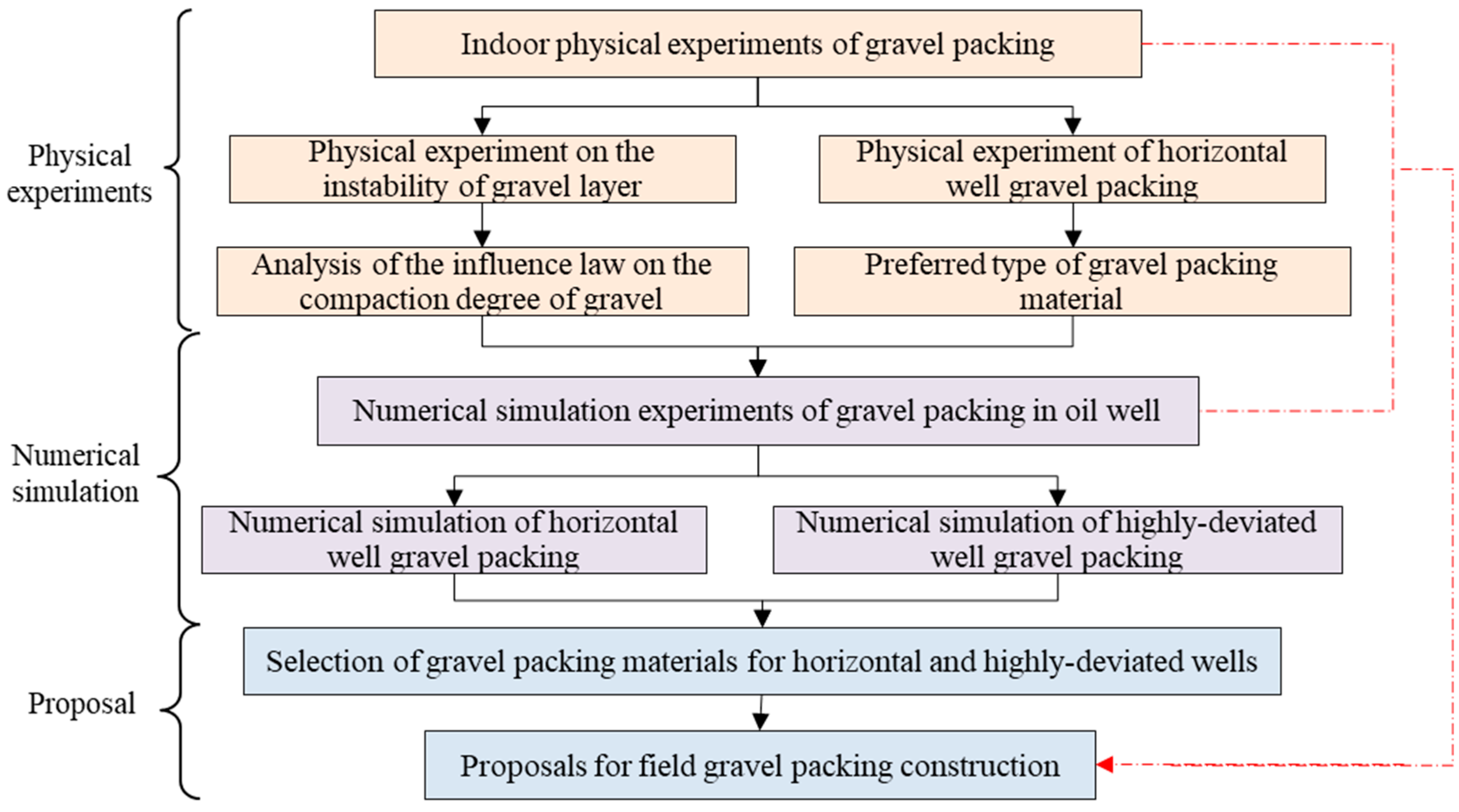
2. Methodology
- (1)
- The density of gravel packing affects the instability morphology of the gravel layer. First, an indoor physical simulation experiment of gravel layer instability is carried out to study the law of gravel layer instability under different gravel packing density conditions.
- (2)
- However, the density of gravel packing is affected by the type of gravel packing. Therefore, an indoor physical simulation experiment of horizontal well gravel packing is carried out. Based on the results of indoor physical simulation experiments, the type of gravel packing material is preliminarily selected to improve the density of gravel packing.
- (3)
- The scale of indoor physical simulation experiments is small and cannot simulate the gravel packing process in actual oil wells. Therefore, based on the actual oil wells in a certain oil field, a numerical simulation study of gravel packing is carried out. Based on the results of numerical simulation experiments, the types of gravel filling materials are selected for horizontal wells and highly deviated wells, respectively.
- (4)
- Finally, the types of gravel filling materials are selected by combining the results of physical experimental simulation and numerical simulation, and construction suggestions are put forward for on-site gravel filling of horizontal wells and highly deviated wells.
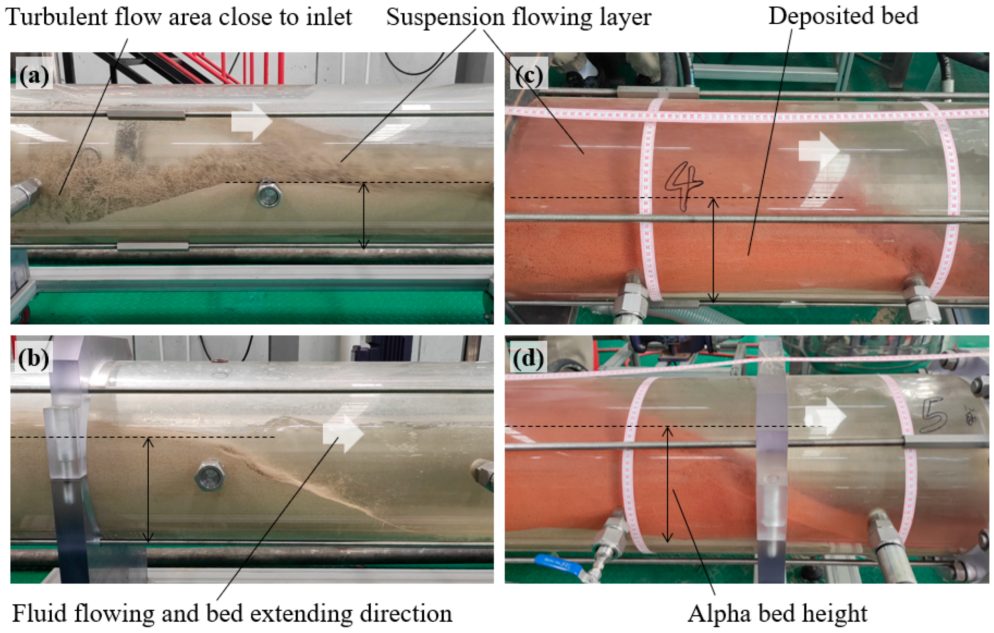
3. Packing Gravel Instability Experiment
3.1. Methods and Materials
3.2. Results and Discussion
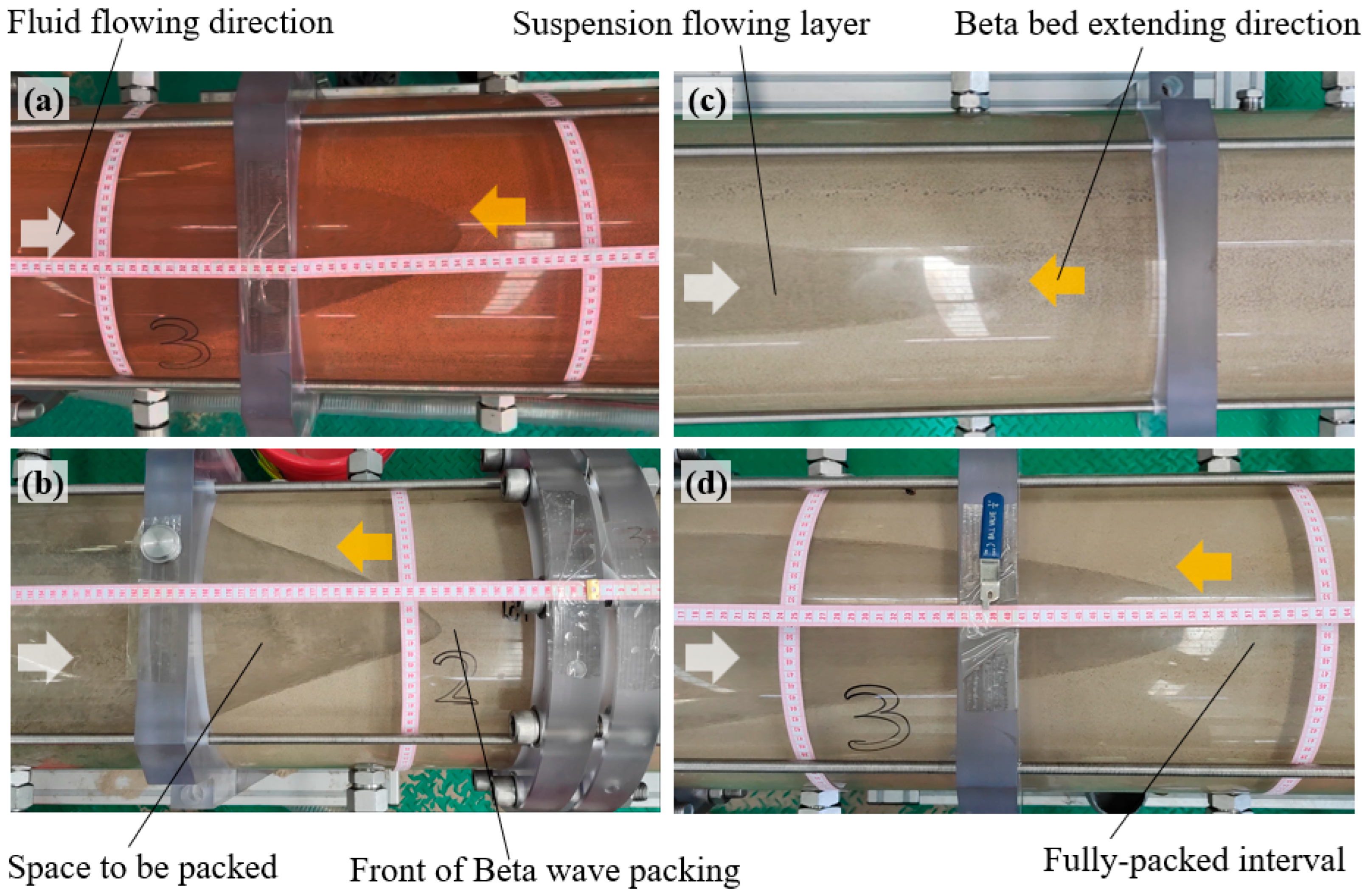
4. Gravel-Packing Experiments
4.1. Method and Materials
4.2. Results and Discussion
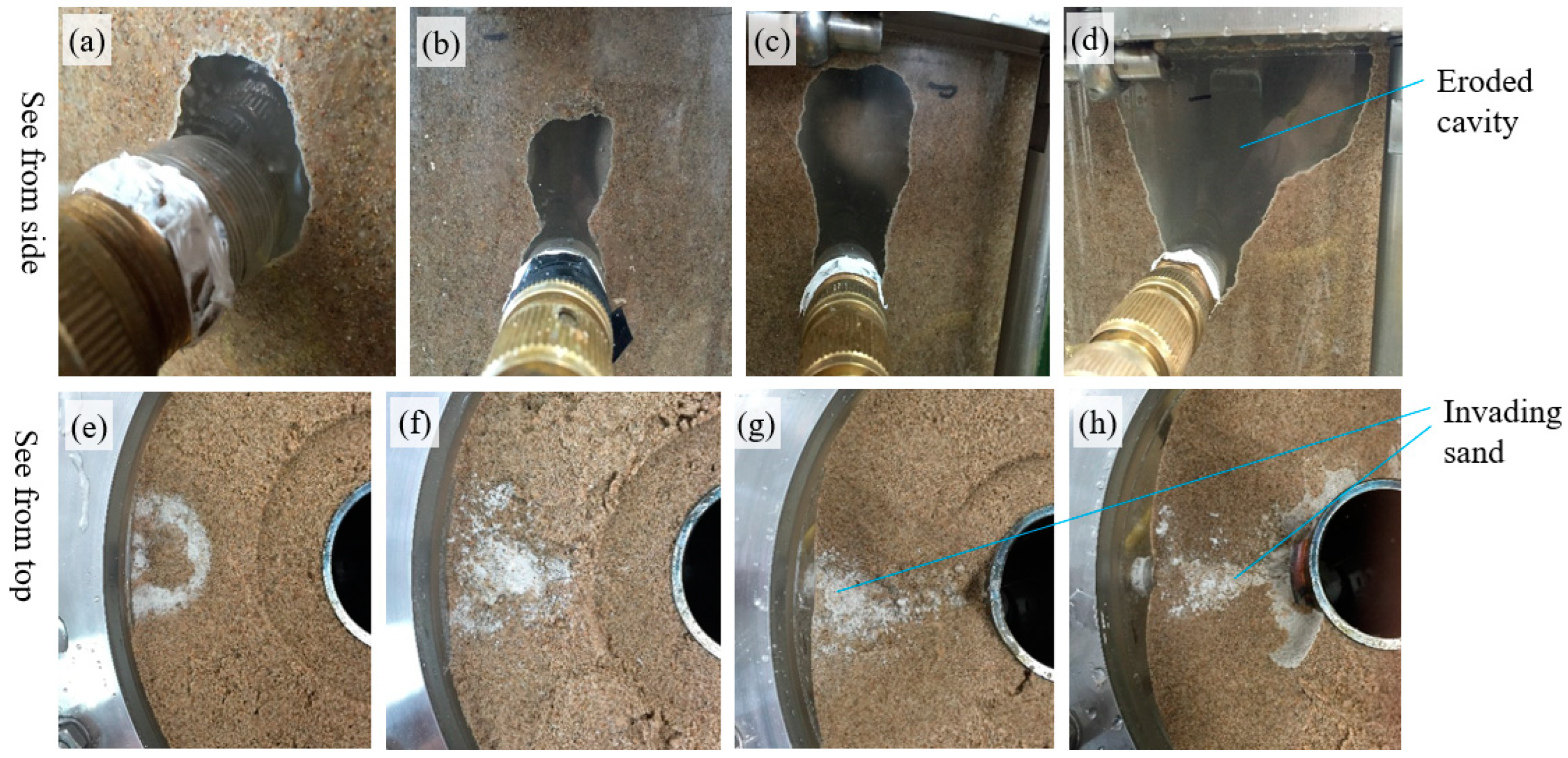
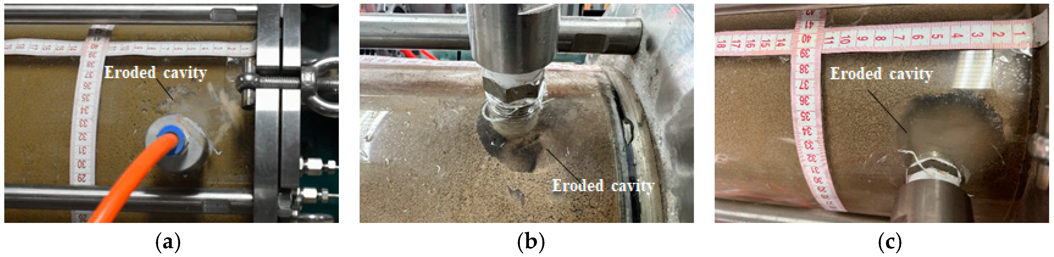
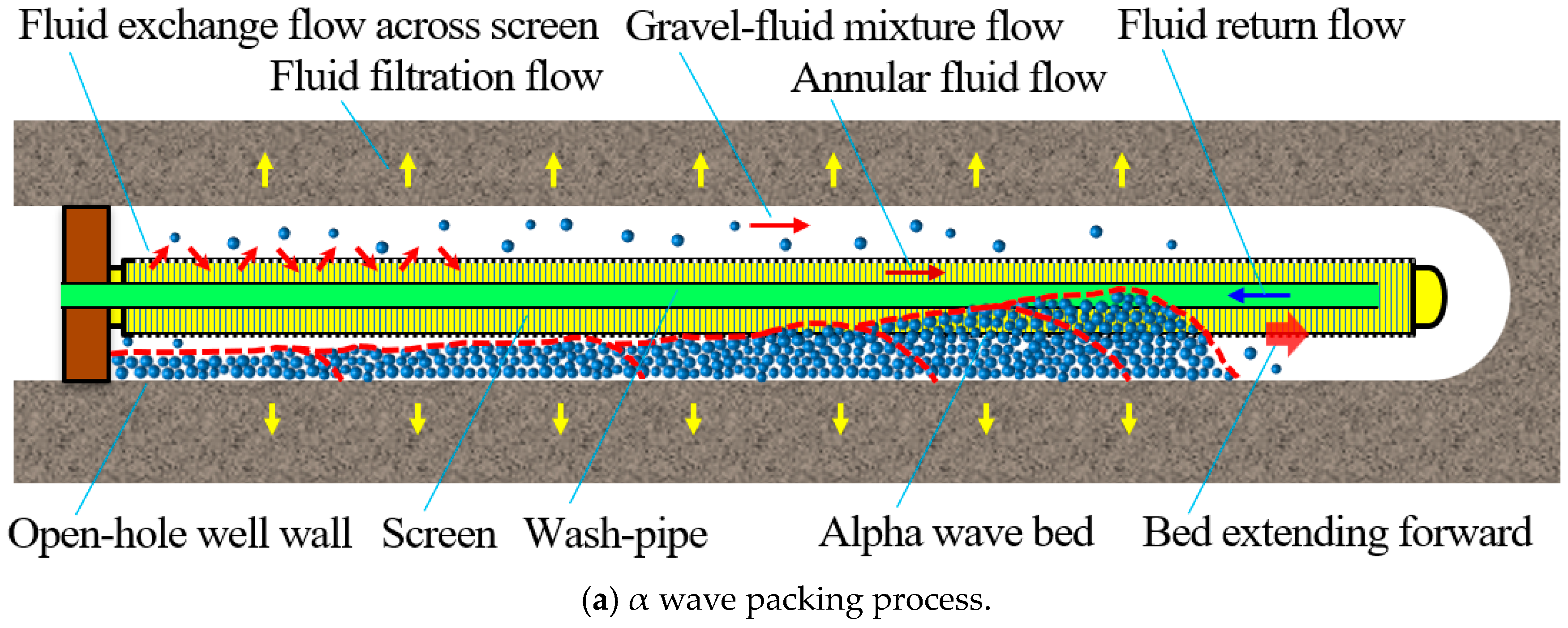
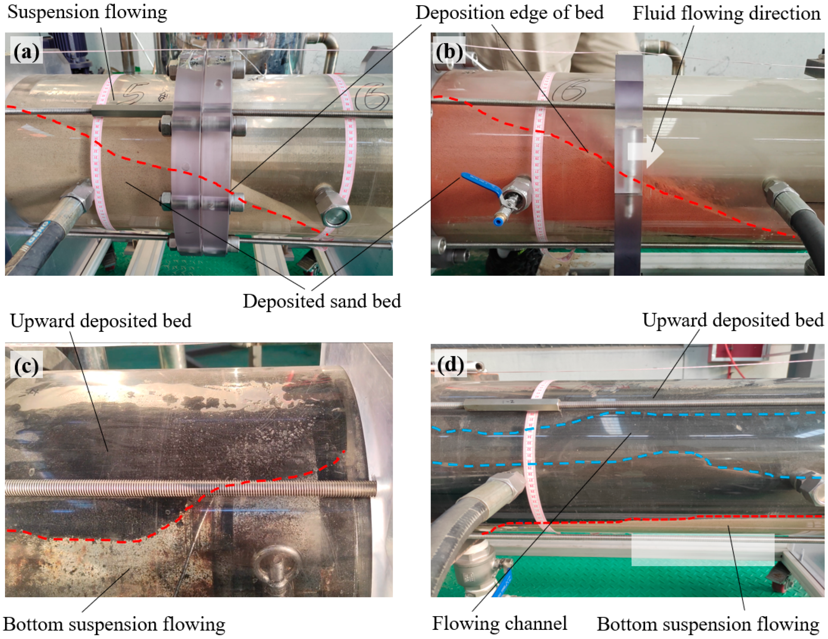
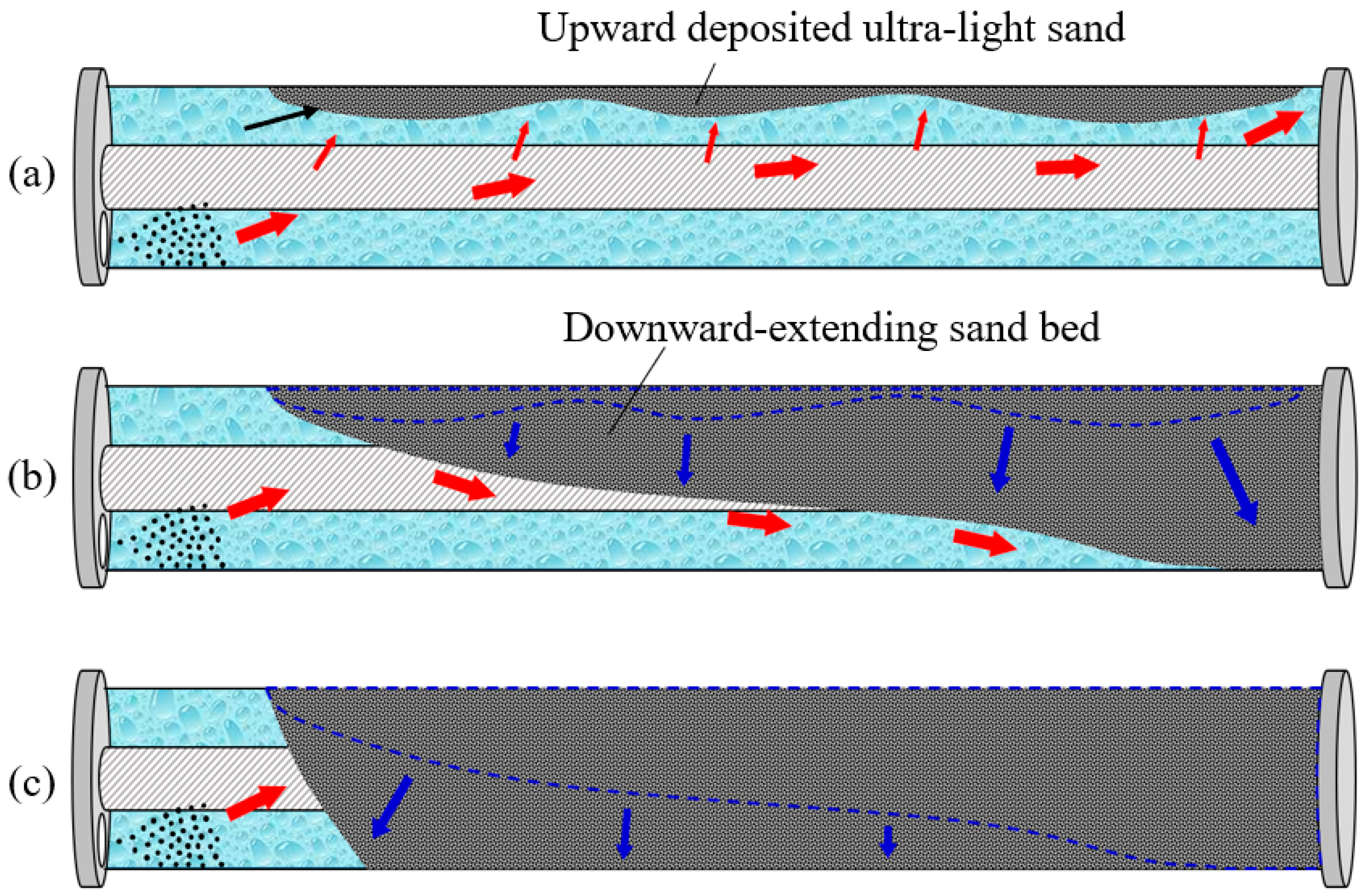
4.2.1. Basic Packing Process Analysis
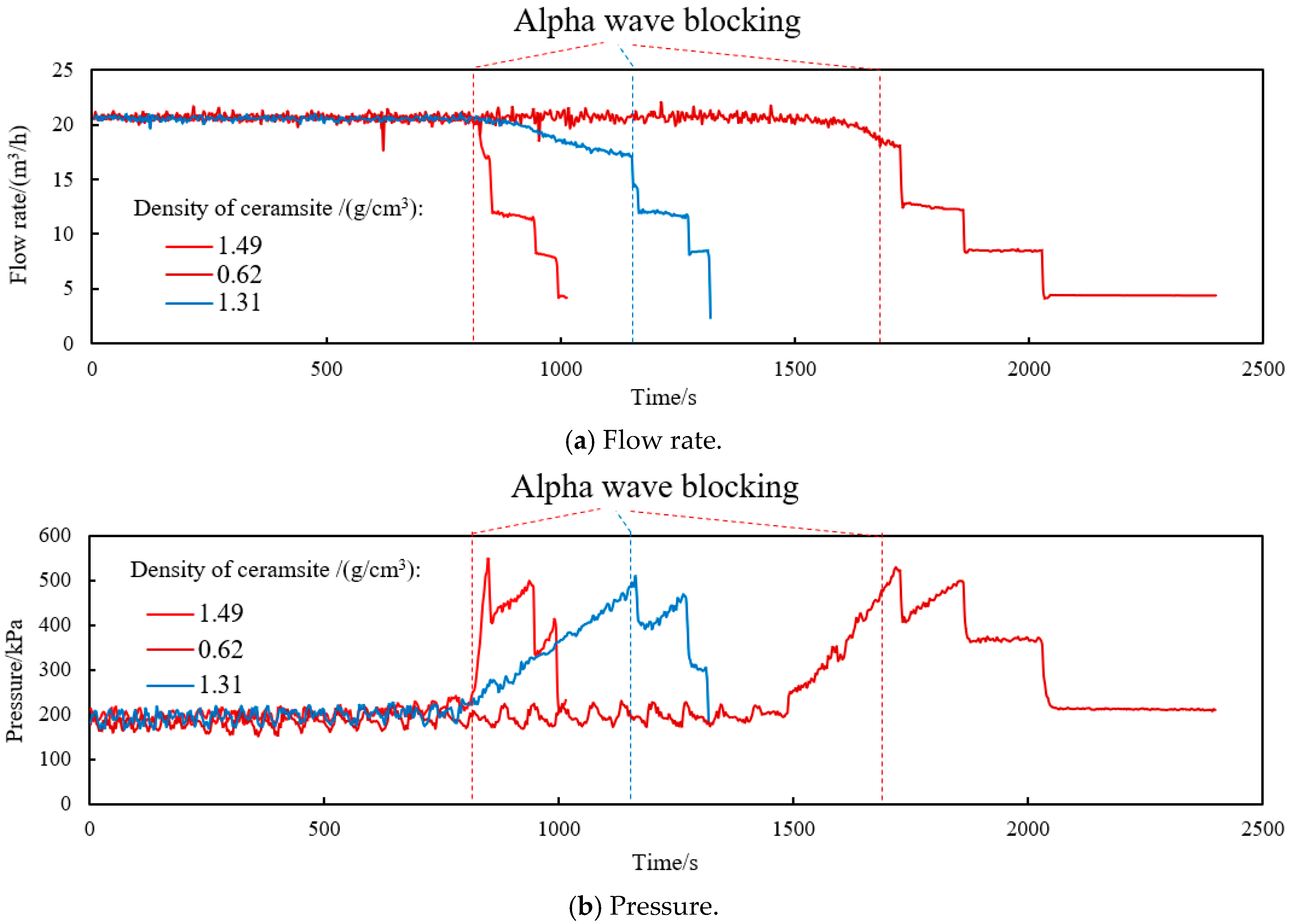
4.2.2. Packing Performance with Different Solid Materials
5. Numerical Simulation Analysis
5.1. Numerical Model and Simulator
5.2. Sensitivity Analysis
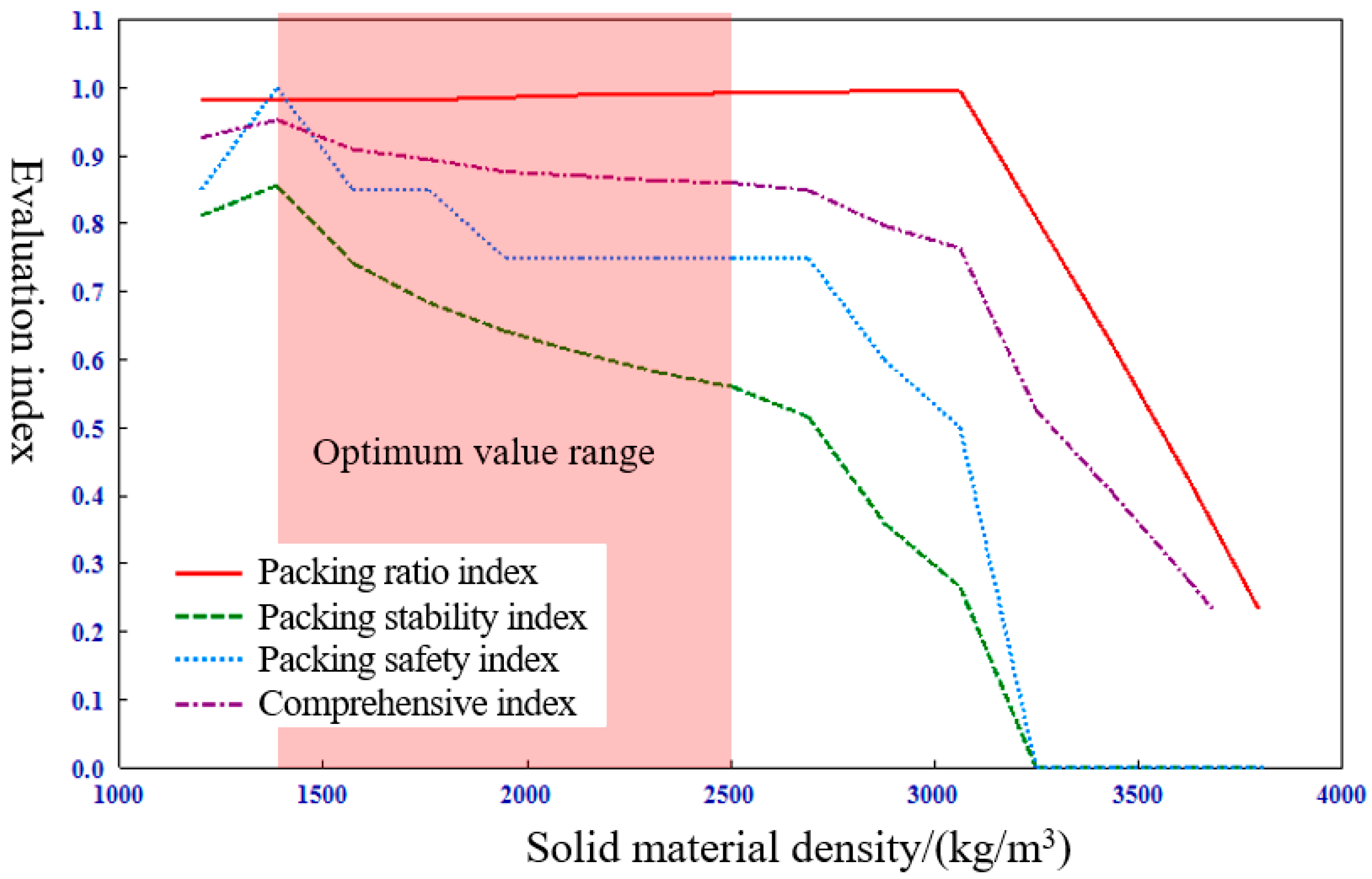
5.2.1. Solid Material Density
5.2.2. Fluid Viscosity
5.2.3. Discussion
6. Recommendations and Conclusions
- (1)
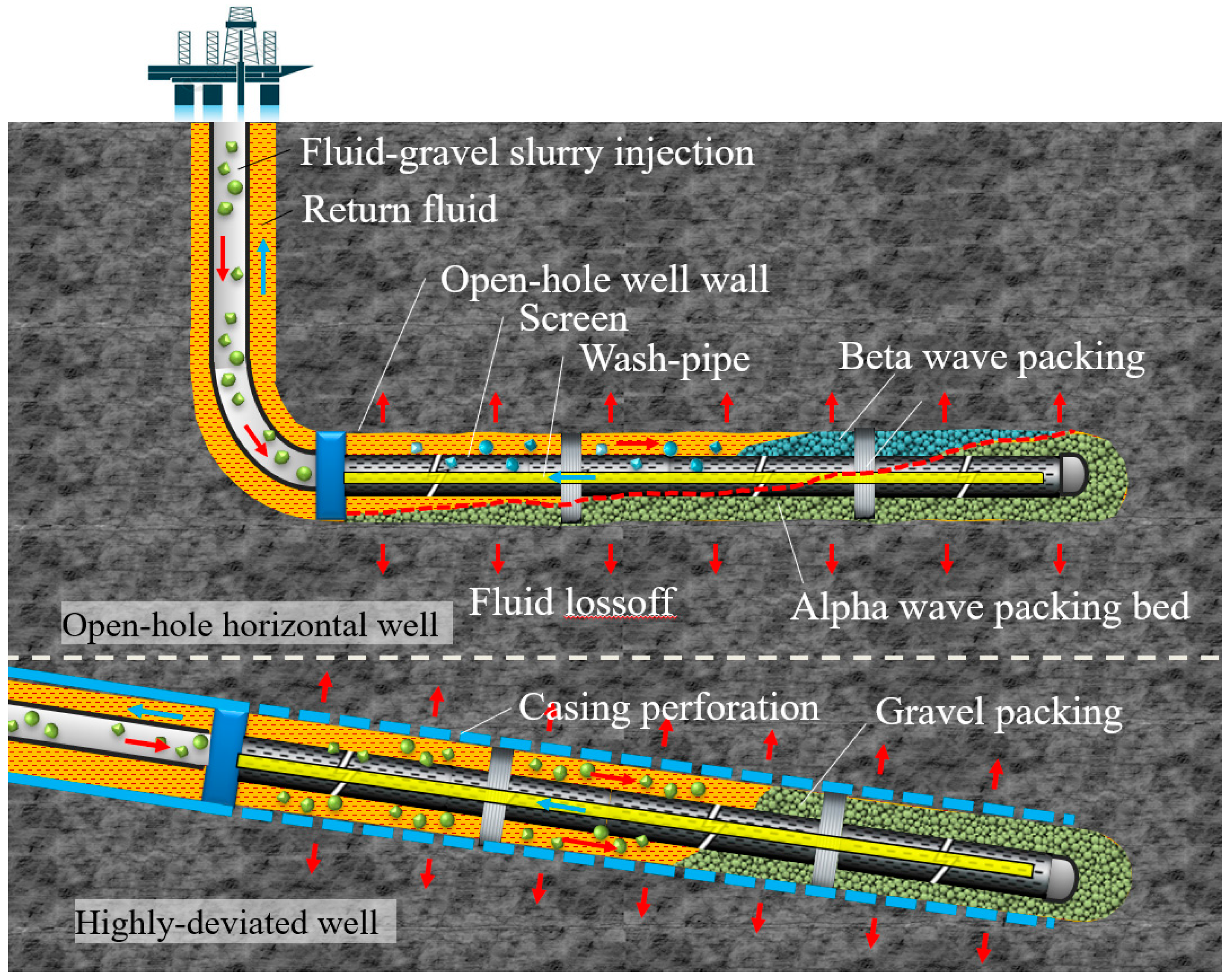
- For gravel-packing in highly deviated wells, due to the deviated wellbore and direction of downward flow, α wave packing can hardly happen. The premature plugging almost won’t happen during the job. Therefore, the usage of high-density solid material can obviously improve the compaction of packing and help to ensure the stability of the packing layer and the effect of sand retention.
- (2)
- In horizontal gravel-packing, which involves α and β wave packing, the gravitational effect of solid material really helps to improve the compaction of packing. So, the utilization of high-density particles favors strengthening the effect of gravity deposition obviously and resultantly improves the effect of sand retention during production.
- (3)
- The density of light or ultra-lightweight solid ceramsite is close to, even smaller than, the density of normal-used carrier fluid. In this case, the effect of gravitational deposition is extremely weak even negligible, which does no favor to the compaction during packing. The compaction degree depends on only the compact of fluid flowing. From the perspective of compaction and sand retention, light and ultra-lightweight ceramsite are not a good choice for horizontal and highly-deviated gravel packing, especially in the case of using high-viscosity fluid. The lightweight solid material will be recommended for use only in one situation, under which the premature plugging of α wave packing can not be avoided under all of the parameters optimization.
Author Contributions
Funding
Institutional Review Board Statement
Informed Consent Statement
Data Availability Statement
Acknowledgments
Conflicts of Interest
References
- Paköz, U.; Ceyhan, A.G.; Aktepe, S.; Cruden, N.; Patey, I.; McLaughlin, R. Formation damage challenges and solutions in cased hole gravel pack completions in deep offshore unconsolidated laminated sandstone formations in the Sakarya Field. Geoenergy Sci. Eng. 2024, 233, 212527. [Google Scholar] [CrossRef]
- Nie, S.; Li, H.; Hu, Z.; Wen, M.; Gao, S.; Zhang, H.; Luo, H.; Zhang, L. A review of the research status and development prospects for gravel packing sand control in horizontal wells. Geoenergy Sci. Eng. 2023, 229, 212152. [Google Scholar] [CrossRef]
- Bhowmick, A.; Amritkar, A.; Ehlig-Economides, C. Determining Gravel Pack Fluidization Velocity. In Proceedings of the SPE Annual Technical Conference and Exhibition, Dallas, TX, USA, 24–26 September 2018. [Google Scholar] [CrossRef]
- Li, Y.; Li, M.; Wang, L.; Yao, Z.; Meng, W. A Productivity Prediction Model for the Gravel-packed Horizontal Well. Pet. Sci. Technol. 2013, 31, 633–642. [Google Scholar] [CrossRef]
- Firth, J.A.; Hamid, H.; Saldungary, P.M. Novel Techniques Enable Successful Gravel Packing of Long Horizontal North Sea Wells. In Proceedings of the SPE Europec, Online, 1–3 December 2020. [Google Scholar] [CrossRef]
- Marques, L.C.; Pedroso, C.A. Cardinal Points to Achieve the Excellence in Horizontal Open-hole Gravel Packing Operations in Deep- and Ultra-deepwaters. In Proceedings of the SPE Annual Technical Conference and Exhibition, Denver, CO, USA, 30 October–2 November 2011. [Google Scholar] [CrossRef]
- Martins, A.L.; de Magalhaes, J.V.M.; Ferreira, M.V.D.; Calderon, A.; de Sa, A.N. Sand Control in Long Horizontal Section Wells. In Proceedings of the Offshore Technology Conference, Houston, TX, USA, 4–7 May 2009. [Google Scholar] [CrossRef]
- Wassouf, P.; Jain, S.; Dannish, G.; Ramnarine, A. Evaluation and Improvement of Gravel Pack Treatments Using Advanced Downhole Pressure Analysis. In Proceedings of the IPTC 2012: International Petroleum Technology Conference, Bangkok, Thailand, 7–9 February 2012. [Google Scholar] [CrossRef]
- Colbert, F.C.; Costa, A.L.; Gachet, R.F.; Garcia, F.M.M.; Neto, A.T. Sand Control Technology for Extended-Reach Wells: Best Practices from the Longest Gravel Packs Performed Offshore Brazil. In Proceedings of the Abu Dhabi International Petroleum Exhibition & Conference, Abu Dhabi, United Arab Emerites, 13–16 November 2017. [Google Scholar] [CrossRef]
- Parlar, M.; Tibbles, R.J.; Gadiyar, B.; Stamm, B. A New Approach for Selecting Sand-Control Technique in Horizontal Openhole Completions. Spe Drill. Complet. 2015, 31, 004–015. [Google Scholar] [CrossRef]
- Sarraf Shirazi, A.; Frigaard, I.A. Gravel packing: How does it work? Phys. Fluids 2020, 32, 053308. [Google Scholar] [CrossRef]
- Tan, M.; Li, Y.; Qi, M.; Wang, H.; Wang, Y.; Lu, J.; Chen, M.; Wu, H. A novel multi-path sand-control screen and its application in gravel packing of deepwater horizontal gas wells. Nat. Gas Ind. B 2022, 9, 376–382. [Google Scholar] [CrossRef]
- Dong, C.; Zhang, Q. Real-time numerical simulation of gravel_packing process in horizontal wells. Acta Pet. Sin. 2004, 25, 96–100. [Google Scholar]
- Mendez, A.; Curtis, J.; Evans, B.; Farias, R. A Quantum Leap in Horizontal Gravel-Pack Technology. In Proceedings of the SPE Latin American and Caribbean Petroleum Engineering Conference, Rio de Janeiro, Brazil, 20–23 June 2005. [Google Scholar] [CrossRef]
- Zhao, X. Research and application of gravel-packing flow-regulation water-control screen completion technique in horizontal wells. IOP Conf. Ser. Earth Environ. Sci. 2019, 227, 042034. [Google Scholar] [CrossRef]
- Changyin, D.; Jiajia, L.; Yanlong, L.; Huaiwen, L.; Lifei, S. Experimental and Visual Simulation of Gravel Packing in Horizontal and Highly Deviated Wells. In Proceedings of the SPE Latin America and Caribbean Petroleum Engineering Conference, Maracaibo, Venezuela, 21–23 May 2014. [Google Scholar] [CrossRef]
- Chen, Z. Horizontal Well Gravel Packing: Dynamic Alpha Wave Dune Height Calculation and Its Impact on Gravel Placement Job Execution. In Proceedings of the SPE Annual Technical Conference and Exhibition, Anaheim, CA, USA, 11–14 November 2007. [Google Scholar] [CrossRef]
- Maly, G.P.; Robinson, J.P.; Laurie, A.M. New Gravel Pack Tool for Improving Pack Placement. J. Pet. Technol. 1974, 26, 19–24. [Google Scholar] [CrossRef]
- Gruesbeck, C.; Salathiel, W.M.; Echols, E.E. Design of Gravel Packs in Deviated Wellbores. J. Pet. Technol. 1979, 31, 109–115. [Google Scholar] [CrossRef]
- Bigna, Y.; Oyeneyin, M.S.; Peden, J.M. Investigation of Pore-Blocking Mechanism in Gravel Packs in the Management and Control of Fines Migration. In Proceedings of the SPE Formation Damage Control Symposium, Lafayette, LO, USA, 7–10 February 1994. [Google Scholar] [CrossRef]
- Sanders, M.W.; Klein, H.H.; Nguyen, P.D.; Lord, D.L. Gravel Pack Designs of Highly-Deviated Wells with an Alternative Flow-Path Concept. In Proceedings of the International Symposium and Exhibition on Formation Damage Control, Lafayette, LO, USA, 20–21 February 2002. [Google Scholar] [CrossRef]
- de Magalhães, J.V.M.; Calderon, A.; de Oliveira, T.J.L.; Pires, I.J.; Martins, A.L. A New Gravel-Pack Approach Using Two Different Proppants in Long Horizontal Well Completions. In Proceedings of the SPE International Symposium and Exhibition on Formation Damage Control, Lafayette, LO, USA, 13–15 February 2008. [Google Scholar] [CrossRef]
- Dong, C.; Wu, L.; Wang, A.; Liu, C.; Zhang, Q. Experimental simulation of gravel-packing in horizontal and highly deviated wells. J. China Univ. Pet. 2010, 34, 74–77. [Google Scholar]
- Sarraf Shirazi, A.; Frigaard, I. A New Three-Layer Model for Gravel Packing Applications in Horizontal Wells. In Proceedings of the ASME 2019 38th International Conference on Ocean, Offshore and Arctic Engineering, Glasgow, Scotland, 9–14 June 2019. [Google Scholar] [CrossRef]
- Xu, F.; Zhou, S.; Zhang, C.; Yu, Y.; Dong, Z. Analysis of Shunted Screen Gravel Pack Process and Calculation of Friction in Deepwater Horizontal Wells. Geofluids 2021, 2021, 4651199. [Google Scholar] [CrossRef]
- Wen, M.; Huang, H.; Zhou, S.; Fan, B.; Qiu, H. Friction calculation and packing effect analysis for gravel packing in deepwater horizontal wells. Energy Sci. Eng. 2021, 9, 2380–2387. [Google Scholar] [CrossRef]
- Peden, J.M.; Russell, J.; Oyeneyin, M.B. A Numerical Approach to the Design of a Gravel Pack for Effective Sand Control in Deviated Wells. In Proceedings of the SPE Annual Technical Conference and Exhibition, Houston, TX, USA, 16–19 September 1984. [Google Scholar] [CrossRef]
- Dong, C.; Zhang, Q. A new probability model for predication of equilibrium sand-bed height for liquid-solid two-phase flowin horizontal pipe. J. China Univ. Petroleum. 2004, 28, 46–48. [Google Scholar]
- Ojo, K.P.; Osisanya, S.O.; Ayeni, K.B. Factors Affecting Horizontal Well Gravel-Pack Efficiency. In Proceedings of the SPE Annual Technical Conference and Exhibition, San Antonio, TX, USA, 24–27 September 2006. [Google Scholar] [CrossRef]
- Ojo, K.P.; Osisanya, S.O.; Ayeni, K.B. 3D Numerical Simulator for Horizontal-Well Gravel Pack. In Proceedings of the SPE Annual Technical Conference and Exhibition, San Antonio, TX, USA, 24–27 September 2006. [Google Scholar] [CrossRef]
- Ojo, K.P.; Osisanya, S.O.; Ayeni, K.B. Development of a 3D Numerical Simulator of Horizontal Well Gravel Pack. In Proceedings of the Canadian International Petroleum Conference, Calgary, AB, Canada, 19–23 June 2006. [Google Scholar] [CrossRef]
- Ojo, K.P.; Osisanya, S.O.; Ayeni, K. Factors Affecting Horizontal Well Gravel Pack Efficiency. J. Can. Pet. Technol. 2008, 47. [Google Scholar] [CrossRef]
- Bai, Y.; Dong, C.; Ren, M. Visual Simulation of Horizontal Gravel-packing and Its Effect Evaluation. Sci. Technol. Eng. 2012, 12, 4149–4153. [Google Scholar]
- Mimouna, A.; Verma, A.; Guddati, M.N. Generalized Framework to Simulate Gravel Packing in Wellbore Completions. In Proceedings of the Offshore Technology Conference, Houston, TX, USA, 20–23 March 2018. [Google Scholar] [CrossRef]
- Huang, H.; Wen, M.; Xing, X.; Qiu, H.; Hou, Z.; Zhou, S. The Gravel Packing Length Determination Method and Influencing Factors Analysis in Deepwater Horizontal Wells. Geofluids 2022, 2022, 2912652. [Google Scholar] [CrossRef]
- Nie, S.; Li, H.; Gao, S.; Hu, Z.; Luo, H.; Li, Q.; Ma, X.; Cui, X.; Liu, Z.; Zhang, L. Numerical simulation and experimental study on the whole process of gravel packing in horizontal wells. Geoenergy Sci. Eng. 2023, 224, 211603. [Google Scholar] [CrossRef]
- Pedroso, C.A.; Sanches, E.D.; Oliveira, N.S.; Fernandes, L.H.; Gomes, M.; Farias, R.; Mendez, A.; Frata, F.M. Lightweight Proppants: Solution for Gravel Packing Horizontal Wells Under Extreme Conditions. In Proceedings of the SPE International Symposium and Exhibition on Formation Damage Control, Lafayette, LO, USA, 15–17 February 2006. [Google Scholar] [CrossRef]
- Trujillo, H.; Tengono, J.A.; Hernández, A.; Castaño, R.; Ortiz, E.; Charry, W.; Anaya, L.A.; Portela, F.; Castillo, R.; López, M.; et al. Long Horizontal Gravel Pack with the Lightest Gravel Ever Used. In Proceedings of the SPE Latin American and Caribbean Petroleum Engineering Conference, Lima, Peru, 1–3 December 2010. [Google Scholar] [CrossRef]
- Chen, Z. The Application of Light and Ultra-Light Weight Proppant in Horizontal Well Sand Control: Unified Model and Case Histories. In Proceedings of the SPE Deepwater Drilling and Completions Conference, Galveston, TX, USA, 20–21 June 2012. [Google Scholar] [CrossRef]
- Denney, D. Ultralightweight Proppants for Long Horizontal Gravel Packs. J. Pet. Technol. 2012, 64, 152–156. [Google Scholar] [CrossRef]


| Type | Apparent Density/g/cm3 | Stacking Density/g/cm3 | Diameter/mm |
|---|---|---|---|
| Normal Ceramicite | 2.76 | 1.49 | 0.425–0.850 |
| Light Ceramicite | 1.92 | 1.31 | 0.425–0.850 |
| Ultra-Light Ceramicite | 1.00 | 0.62 | 0.425–0.850 |
Disclaimer/Publisher’s Note: The statements, opinions and data contained in all publications are solely those of the individual author(s) and contributor(s) and not of MDPI and/or the editor(s). MDPI and/or the editor(s) disclaim responsibility for any injury to people or property resulting from any ideas, methods, instructions or products referred to in the content. |
© 2024 by the authors. Licensee MDPI, Basel, Switzerland. This article is an open access article distributed under the terms and conditions of the Creative Commons Attribution (CC BY) license (https://creativecommons.org/licenses/by/4.0/).
Share and Cite
Shi, H.; Dong, C.; Zhan, X.; Liu, C.; Li, L.; Ji, J.; Yu, Y.; Li, Z. Selection Results of Solid Material for Horizontal and Highly-Deviated Well Completion Gravel-Packing: Experiments, Numerical Simulation and Proposal. J. Mar. Sci. Eng. 2024, 12, 1690. https://doi.org/10.3390/jmse12101690
Shi H, Dong C, Zhan X, Liu C, Li L, Ji J, Yu Y, Li Z. Selection Results of Solid Material for Horizontal and Highly-Deviated Well Completion Gravel-Packing: Experiments, Numerical Simulation and Proposal. Journal of Marine Science and Engineering. 2024; 12(10):1690. https://doi.org/10.3390/jmse12101690
Chicago/Turabian StyleShi, Haoxian, Changyin Dong, Xinjie Zhan, Chenfeng Liu, Lixia Li, Jianrong Ji, Yanjiang Yu, and Zhendong Li. 2024. "Selection Results of Solid Material for Horizontal and Highly-Deviated Well Completion Gravel-Packing: Experiments, Numerical Simulation and Proposal" Journal of Marine Science and Engineering 12, no. 10: 1690. https://doi.org/10.3390/jmse12101690
APA StyleShi, H., Dong, C., Zhan, X., Liu, C., Li, L., Ji, J., Yu, Y., & Li, Z. (2024). Selection Results of Solid Material for Horizontal and Highly-Deviated Well Completion Gravel-Packing: Experiments, Numerical Simulation and Proposal. Journal of Marine Science and Engineering, 12(10), 1690. https://doi.org/10.3390/jmse12101690