Article

Effect of Speed Linear Decrease on Internal Flow Characteristics and Pressure Pulsations of Variable-Speed Pump Turbine in Turbine Mode

1
Key Laboratory of Fluid and Power Machinery (Xihua University), Ministry of Education, Chengdu 610039, China
2
Department of Energy and Power Engineering, Tsinghua University, Beijing 100084, China
*
Author to whom correspondence should be addressed.
J. Mar. Sci. Eng. 2024, 12(12), 2243; https://doi.org/10.3390/jmse12122243
Submission received: 1 November 2024 / Revised: 23 November 2024 / Accepted: 4 December 2024 / Published: 6 December 2024
(This article belongs to the Section Ocean Engineering)

Abstract

:
Pumped storage units often deviate from the optimal operating conditions in the process of regulating new energy fluctuations. To effectively improve the performance of the units, the variable speed of the units is one of the more feasible means at present. This paper focuses on the part-load condition of turbine operation, with an emphasis on the internal flow characteristics and pressure pulsation characteristics of the pump turbine during the linear reduction of the rated speed. It is found that the streamlines in the runner become turbulent in the process of speed reduction, forming a vortex at the inlet of the runner, and the vortex scale gradually increases with the speed reduction. The vortex rope in the draft tube undergoes three types of changes during the speed reduction: helical eccentric vortex rope, vanishing vortex rope, and columnar vortex rope. Before the speed change, the low-frequency components with high amplitude exist in each flow-passing part, but gradually disappear with the speed reduction. Except for the runner, the frequency affected by rotor–stator interference of each flow-passing part increases with the decrease of speed, and the growth is most obvious in the vaneless region. The findings of this research can serve as a valuable reference for the variable speed operation of pumped storage units.

1. Introduction

In order to achieve the “double carbon” goal centered on “carbon peak” and “carbon neutrality” as soon as possible, new energy sources such as wind power, solar thermal photovoltaic power generation, and other new energy sources will be integrated into the power grid on a large scale. However, due to the wind, light energy-based new energy is very susceptible to weather changes, with randomness and mutability, and its large-scale integration will threaten the safe and stable operation of the power grid [1]. Pumped storage units provide an effective solution to ensure the reliable operation of the power system; combining pumped storage systems with renewable energy sources such as light and wind energy not only enhances their ability to provide stable power output, but also contributes to the overall stability of the power grid [2,3,4,5]. For the rapid development of coastal nuclear power, island fuel power generation, offshore wind power and offshore photovoltaic power generation at sea are in urgent need of a seawater pumped storage power plant to help solve the instability, intermittency, and other issues. However, this also means that the probability of hydropower units operating under non-design conditions will increase significantly. Under non-design conditions, the flow pattern deteriorates, pressure pulsation amplitude increases, and the intensification of vibration would seriously threaten the stable operation of the units [6,7,8]. The selection of variable-speed pumped storage units provides a solution to effectively improve the performance of the units during operation and to meet the demand for power and frequency regulation in the power grid. For seawater pumped storage, variable-speed operation of the unit not only facilitates the combination of seawater pumped storage with the development of new marine energy sources such as offshore wind power and photovoltaic power in the coastal areas [9], but also moderates the impact of waves generated by typhoons, tides, and ocean currents on the unit’s effective drop and hydro-mechanical operation.
Two types of motors are available for variable speed technology: the doubly fed induction motor (DFIM) or full-size frequency converter (FSFC). Experience has shown that due to thermal limitations, the speed of a DFIM cannot vary by more than ±10% of the rated speed. The FSFC, in practice, allows speed variations within ±30% of the rated speed [10].
Many researchers have conducted extensive studies on motors [11,12], control strategies [13,14], and power regulation [15,16] for variable speed power systems. For hydroelectric units, the research has focused on aspects such as energy efficiency gains, pressure pulsations, and cavitation characteristics.
Heckelsmueller et al. [17] pointed out that when the Francis turbine is operated under non-design head conditions, the variable speed technology is capable of enhancing the efficiency of the unit. Bortoni et al. [18] verified this conclusion through theoretical analysis and experiments. Yu et al. [19] further corroborated that the adoption of variable speed technology under non-design head conditions and partial load conditions can improve the unit’s efficiency by quantitatively analyzing the energy utilization performance of the hydraulic turbine during fixed and variable speed operations. Feng et al. [20] demonstrated that the pumped storage unit can effectively avoid the entry into the S-shaped region by variable speed maneuvering. Nevertheless, these studies merely focused on analyzing the external characteristics of the variable speed process. The alteration of operating conditions will unavoidably modify the internal flow state of the unit, yet there is a dearth of research in this regard.
Changes in flow state also affect the pressure pulsation. There are many reasons for pressure pulsation, such as rotor-stator interaction [21], rotational stall [22], and vortex distribution [23,24]. Currently, many scholars have some studies on pressure variations caused by variable speed operation. For example, Trivedi et al. [25,26] conducted a test which revealed that the amplitude of pressure pulsations in each flow-passing parts of Francis turbine varies with the speed. Rode et al. [27] found that the main source of pressure fluctuations in the variable speed RPT at the best efficiency point and high-head operating conditions is rotor–stator interaction. Shang et al. [28] showed the pressure pulsation of a pump turbine in pump mode at maximum speed. The article only investigated the pressure pulsation of the pump turbine at a fixed rotational speed, and it was not possible to know how the pressure pulsation varied with increasing rotational speed Li et al. [29] investigated the trajectory on the pressure pulsation contour and discovered that the value of pressure pulsation increases with the increase of initial speed or speed command. However, they only studied the change rule of pressure pulsation amplitude, and did not study the change rule of the main frequency. Trivedi et al. [30] probed the cavitation characteristics and pressure pulsation of the hydraulic turbine during the increase of speed and found that the cavitation effect is extremely significant at certain moments. The amplitude of the pressure pulsation is significantly high due to the eruption of cavitation bubbles. Lv et al. [31] identified that unit cavitation characteristics can be improved by variable speed.
From the above studies, it can be seen that many researchers have carried out a lot of studies on the variable speed technology of hydropower units, but there is still a relative lack of research on the internal flow characteristics and pressure pulsation characteristics of the pump turbine with the change of speed. This paper focuses on the part-load condition of turbine operation, with an emphasis on the internal flow characteristics and pressure pulsation characteristics of the pump turbine during the linear reduction of the rated speed. It provides a reference for the stable operation of variable speed pump turbines.

2. Specifications of the Pump Turbine

Figure 1 shows the three-dimensional view of the CFD computational domain of the pump turbine, which consists of five parts: the spring casing, the stay vanes, the guide vanes, the runner, and the draft tube. The basic parameters of the model are listed in Table 1. Since the probability of the hydropower unit operating in non-designed conditions has increased significantly after the large-scale integration of new energy sources such as wind power and photovoltaic power generation into the power grid, this paper carries out the study under the part-loaded condition of the pump turbine in turbine mode. A guide vane opening of 19 mm was chosen as the initial condition to carry out the study of the variable speed process.
In this paper, we only study the transient flow characteristics and pressure pulsation characteristics in the process of speed change. In order to facilitate the analysis, after referring to the relevant literature, the speed is set to change according to the following formula:
t 0 t t 1 , n = n 1
t 1 < t < t 2 , n = n 1 + n 2 n 1 t 2 t 1 t
t 2 t t 3 , n = n 2
where t0 = 0 s, t1 = 1.1 s, t2 = 3.1 s, t3 = 4.1 s.

3. Numerical Simulation

3.1. Mesh Generation and Irrelevance Verification

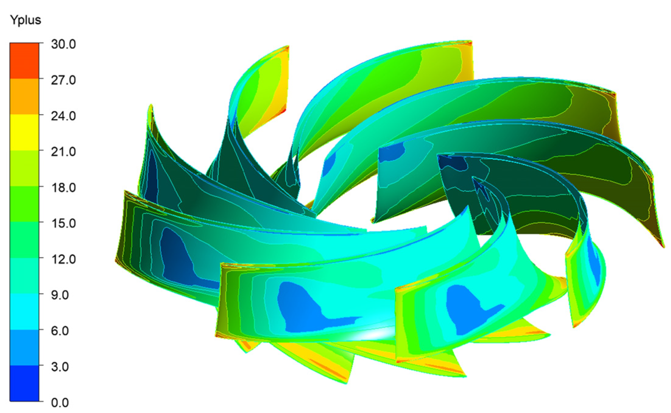
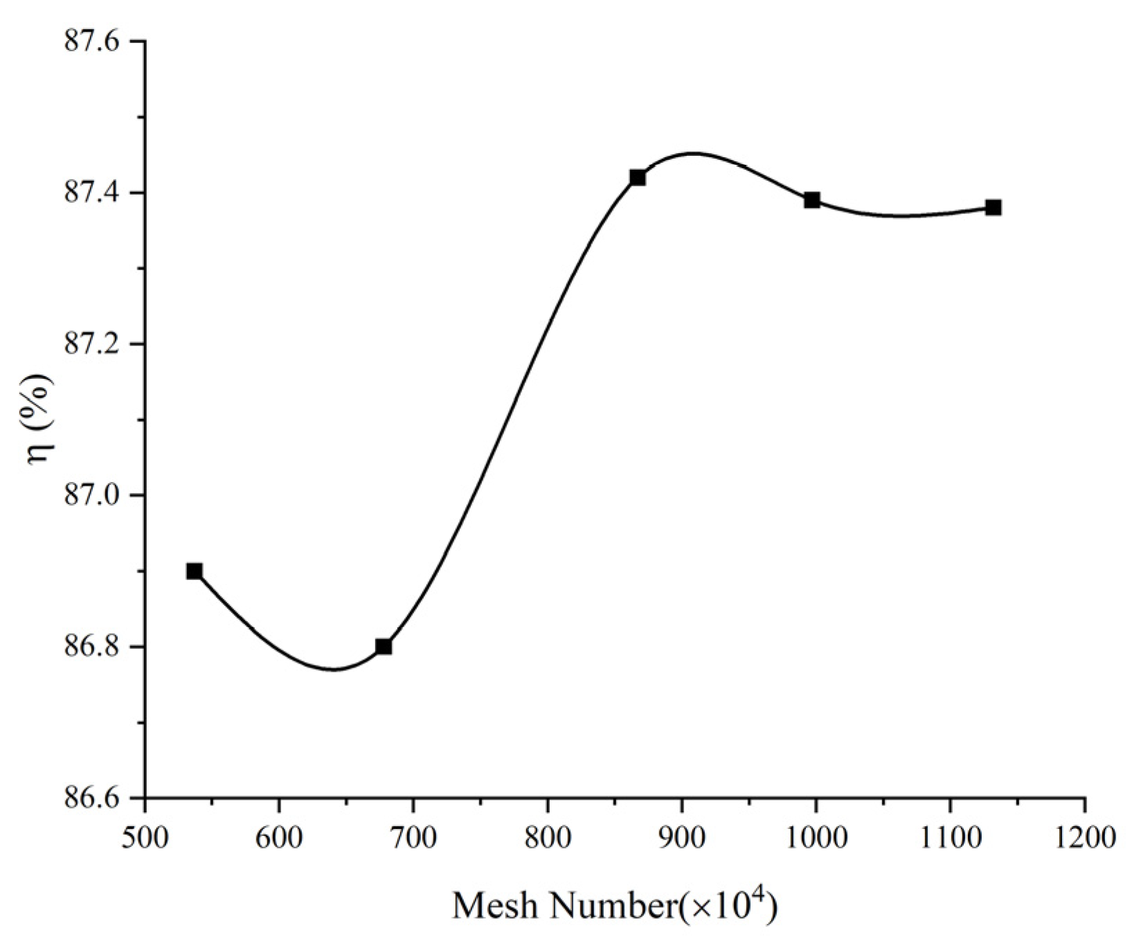
All the flow-passing parts are meshed as displayed in Figure 2, where the runner, stay vanes, and draft tube are meshed with a hexahedral mesh, while the spring casing and guide vanes are meshed with a tetrahedral mesh. Figure 3 displays the distribution of Y+ values for the runner components, which conforms to the Y+ values required by the SST turbulence model. In order to avoid the influence of the number of grids on the transient calculation, the irrelevance of the grids is verified. Five groups of grids are selected and simulated at the same head, and the results are summarized in Figure 4. When the number of grids is larger than 8.5 million, the hydraulic efficiency of the pump turbine is less affected by the number of grids. The total number of grids of the computational domain is determined to be 9.97 million by comprehensive consideration of the computational accuracy and computational resources.

3.2. Turbulence Model Selection and Boundary Condition Setting

In this paper, the working fluid is water, which is considered as an incompressible fluid. This study does not involve the exchange of heat. Therefore, the fluid motion can be derived from the conservation of mass and momentum, and the governing equations are listed below.
The continuity equation is:
ρ t + ( ρ u ) = 0
In the above formula:
ρ —fluid density
u —velocity vector
The momentum conservation equation is:
u t + ( u ) u = f 1 ρ p + ν 2 u
In the above formula:
f —body force
p —pressure
ν —coefficient of kinetic viscosity.
In this paper, the SST k-ω turbulence model is chosen to carry out the numerical study of the pump turbine variable speed process. It is because the SST k-ω turbulence model combines the advantages of the k-ω turbulence model and the K-e turbulence model, which not only takes into account the turbulent shear stress, but also avoids the extreme prediction of the eddy viscosity coefficient.
The equations for the SST turbulence model are:
ρ κ t + ρ u i κ x i = x i μ + σ κ μ t κ x i + τ i j u i x i β * ρ ω κ
ρ ω t + ρ u i ω x i = x i μ + σ ω μ μ ω x i + 2 ( 1 F 1 ) σ ω 2 ω κ x i ω x i
In the above formula:
κ —turbulent kinetic energy
ω —specific dissipation rate
μ —eddy viscosity
F 1 —blending function
σ ω μ , β * , σ ω , σ ω 2 —closure constant
In this study, CFX is used for numerical simulation. It is assumed that the head is constant. A pressure-inlet is installed at the inlet of the spiral casing. The outlet of the draft tube is designated as a static pressure outflow, and the relative reference pressure is set to 0 Pa. No-slip wall is set to turbine solid walls. The transient time step is specified as 0.0005 s. The residual convergence criterion is set to 10−5, and the calculation is considered to be converged when the residual values of all variables are lower than 10−5.

4. Numerical Simulations and Validation

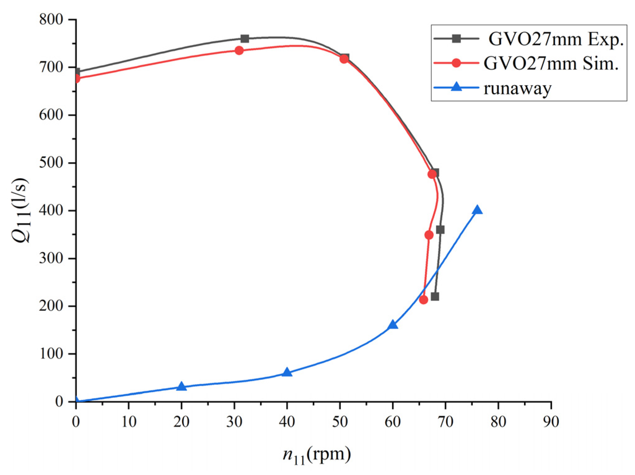
In order to verify the accuracy and reliability of the numerical calculation method in this paper, the numerical calculation results are compared with the test results for a series of working points under the rated opening of a hydraulic turbine of 27 mm. The test adopts the settings of the pressure inlet and pressure outlet, so as to obtain the rotational speed and flow rate at different working conditions. The simulation is based on the speed and flow obtained from the tests to set the boundary conditions, i.e., the flow inlet and hydrostatic outlet, and to monitor the head. The head sizes are obtained from the tests and the calculations are compared under the same speed and flow conditions. The calculated results are shown in Figure 5 after converting the unit parameters according to Equations (8) and (9). The comparison shows that the error rate of the head is less than 5%, and the simulation results can be used as a basis for analysis.
n 11 = n D H
Q 11 = Q D 2 H
where n is the rotational speed, D is the nominal diameter of the runner, H is the head and Q is the flow rate.

5. Results and Discussion

5.1. External Characteristics

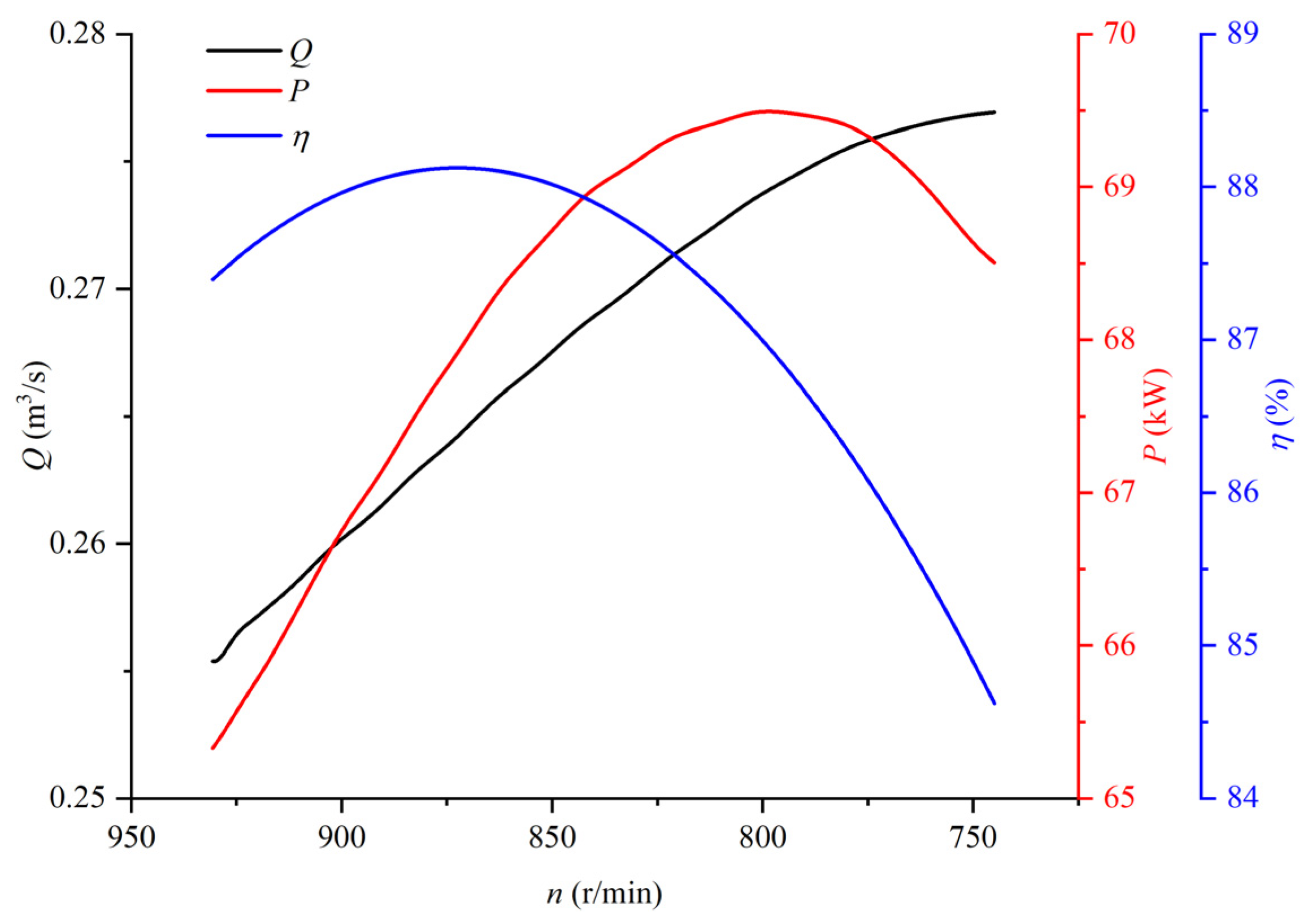
The variable speed process of the pump turbine under power generation conditions is simulated when the guide vane opening is 19 mm. When the speed is decreased from the rated speed of 931.128 r/min to 744.9 r/min, i.e., the speed is decreased by 20%. The calculation results are presented in Figure 6. During the speed decrease process, the flow rate is increased and the torque is increased at approximately the same rate. The power output (P = TW) is related to the speed and the torque. The power output shows a tendency to increase and then decrease when the speed decreases, and reaches the maximum value after 2.5 s of speed change at 800 r/min. The efficiency also increases and then decreases as the speed decreases, and it is maximum when the speed is 875 r/min. It can be seen that the adjustment of the output force and efficiency during variable speed operation is a complex process.

5.2. Internal Flow Characteristics in the Runner

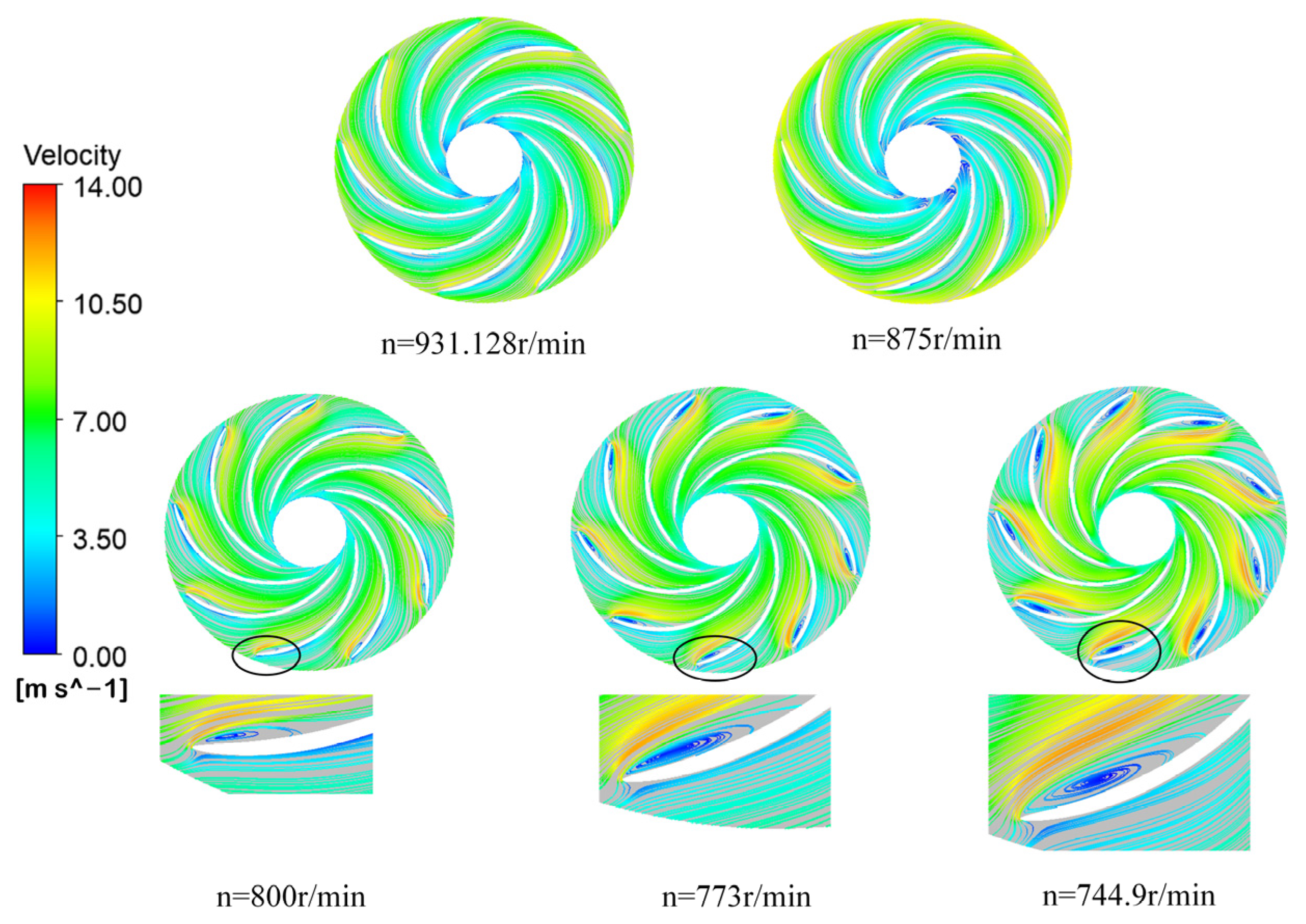
In order to analyze the flow characteristics during the speed reduction process, Figure 7 shows the velocity streamline on the 0.5-span surface on the runner at five typical moments. It is observable from the figure, from the rated speed to the optimal efficiency corresponding to the speed of 875 r/min, that the streamlines between the blades are smooth, and there is no significant flow separation or vortex. With the reduction of speed, the circumferential velocity U1 decreases accordingly. As the opening of the guide vanes is constant, the absolute flow angleα1 is unchanged. The absolute velocity V1 increases with the increase of discharge. As shown in Figure 8, the relative flow angle is greater than β (the angle between the center line of blade profile and the circumferential velocity). The flow strikes the blade pressure surface at a positive angle of attack, leading to a flow separation at the inlet suction surface of the runner. The flow produces a rotational velocity component. Meanwhile, a vacuum generated by this separation pulls in more water flow, boosting the rotational velocity component and creating a swirl within the passage to form a vortex. With the further reduction of speed, and when the speed is 744.9 r/min, the streamlines inside the runner are more turbulent and the vortex scale is further increased.

5.3. Evolution of Vortex Structure in the Draft Tube

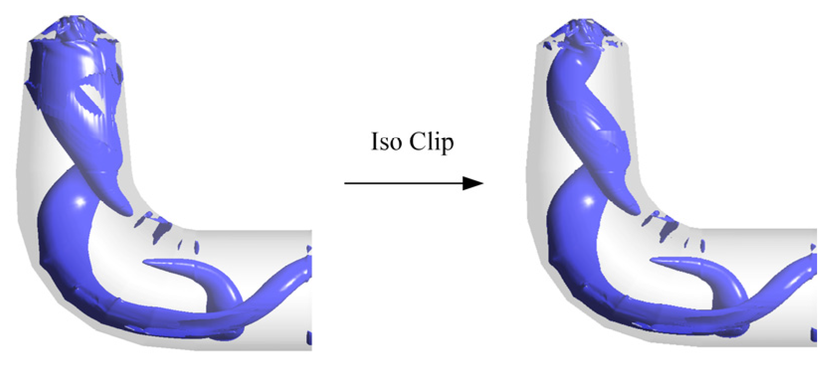
The vortex within the draft tube is identified using the Q criterion. In the three-dimensional view, as shown in Figure 9, the interference of the shear layer on the wall surface of the draft tube cone is serious, resulting in the appearance of a sheet vortex structure, which remains basically unchanged in position and number with the change of speed. Therefore, in the subsequent analysis of the vortex, in order to make the vortex structure in the center clearly visible, the sheet vortex is cut off during the post-processing.
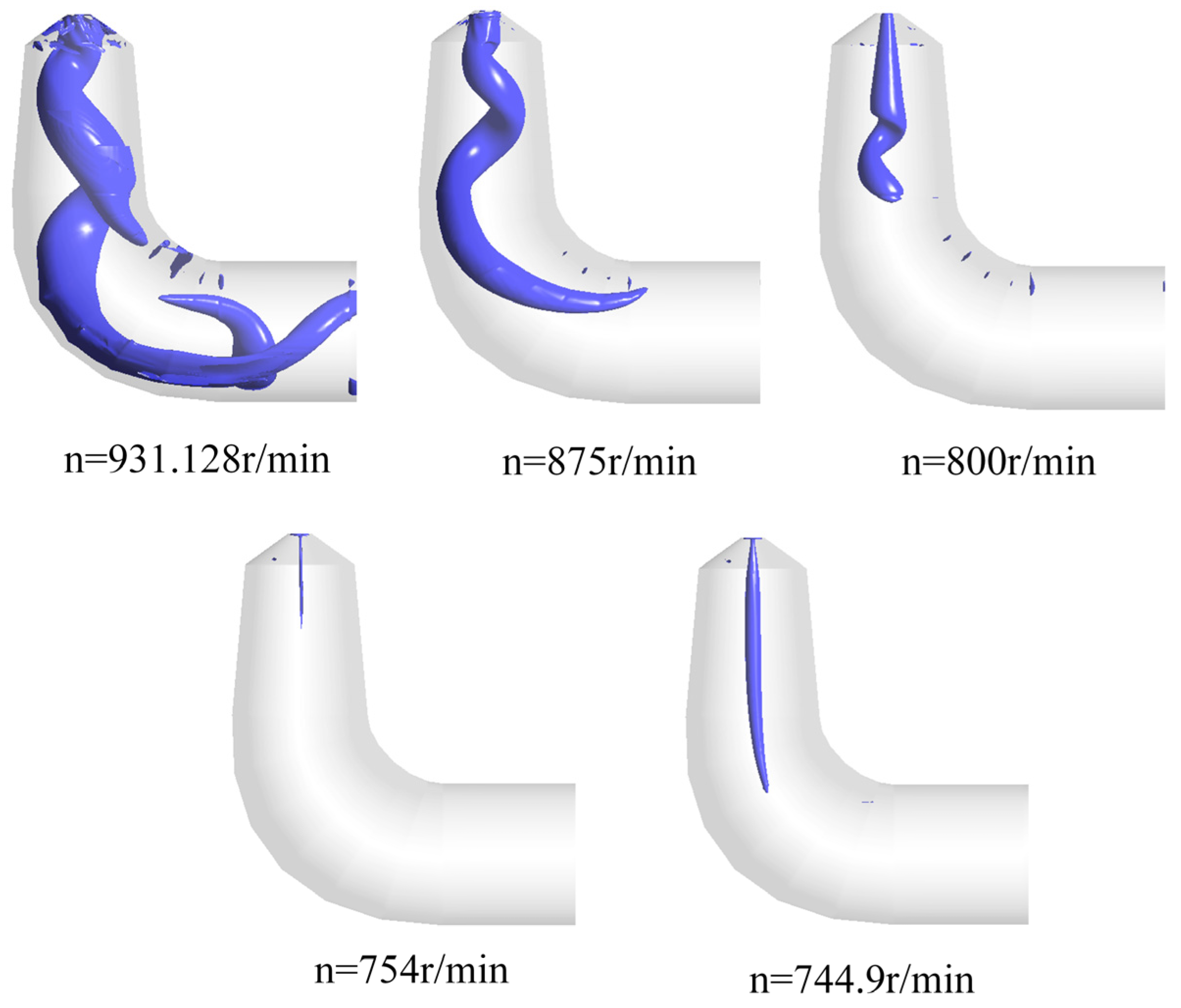
The most fundamental condition for generation of the draft tube vortex rope is that the flow at the outlet of the runner has a certain circumferential velocity component V2u. In order to have a deeper understanding of the evolution of the vortex structure in the draft tube during the speed changes, Figure 10 and Figure 11 show the vortex structure in the draft tube and the velocity triangles at the runner outlet, respectively, for the variable speed process.
In the small opening rated speed conditions, the pump turbine does not run in the optimal operating conditions, which will make the runner outlet produce a residual vortex. At this time, the runner outlet flow has a certain circumferential velocity component V2u, and the direction of this circumferential velocity component is the same as that of the runner’s rotation. The vortex shape displayed in the draft tube is a single helical eccentric vortex structure with high strength, as shown in Figure 10. This helical eccentric vortex belt performs the same rotational motion as the runner’s rotation. As the speed decreases, the discharge increases, the runner outlet circumferential velocity component V2u decreases, the circulation at the inlet of the draft tube is also reduced, the intensity and scope of the vortex rope are weakened, the vortex structure shrinks along the axis, and the radius of the vortex core decreases in the radial direction. When the speed is reduced to near 754 r/min, the runner outlet flow is close to the normal outflow, the circumferential velocity component V2u is almost zero (illustrated in Figure 11). At this point, the runner outlet velocity circulation is zero, and the vortex rope has almost disappeared. As the speed decreases further, the discharge increases further, the runner outlet circumferential velocity component V2u opposes the orientation of the runner rotation, forming a negative flow circulation at the draft tube inlet, at which time the vortex structure in the draft tube center is shown as a column. As the speed decreases, the vortex structure increases along the axial direction, and its vortex core radius increases in the radial direction.

5.4. Change of Axial Velocity of Draft Tube

To further explore the formation process of the vortex rope, the axial velocity cloud diagrams and velocity vector distributions in the draft tube in the transient process of variable speed were analyzed, as shown in Figure 12.
It is observable from Figure 12 that the flow regime inside the draft tube is turbulent at the rated speed. Multiple vortex structures appear within the draft tube cone, which form a certain extrusion effect on the flow and make the high-speed zone appear near its wall. The low-speed zone is shown as an “S” shape. In the center of the draft tube cone and the elbow section, the axial velocity is positive, opposite to the direction of flow in the draft tube. During the decrease in the rated speed to 875 r/min, the axial velocity distribution is relatively similar, but the extent of the high velocity zone near the wall and the low velocity zone in the draft tube is narrowed. With the reduction of speed to 800 r/min, the range of the low velocity zone is nearly reduced, the angle between the direction of the axial velocity and the axis of the draft tube is reduced, and the degree of flow offset is significantly reduced, indicating that the reduction of the speed of the pump turbine further enhances the hydraulic stability in the draft tube. With a further reduction in speed, the axial velocity in the draft tube is almost entirely in the same direction as the main flow, and the axial velocity value is higher near the center and lower near the wall.

5.5. Pressure Pulsation

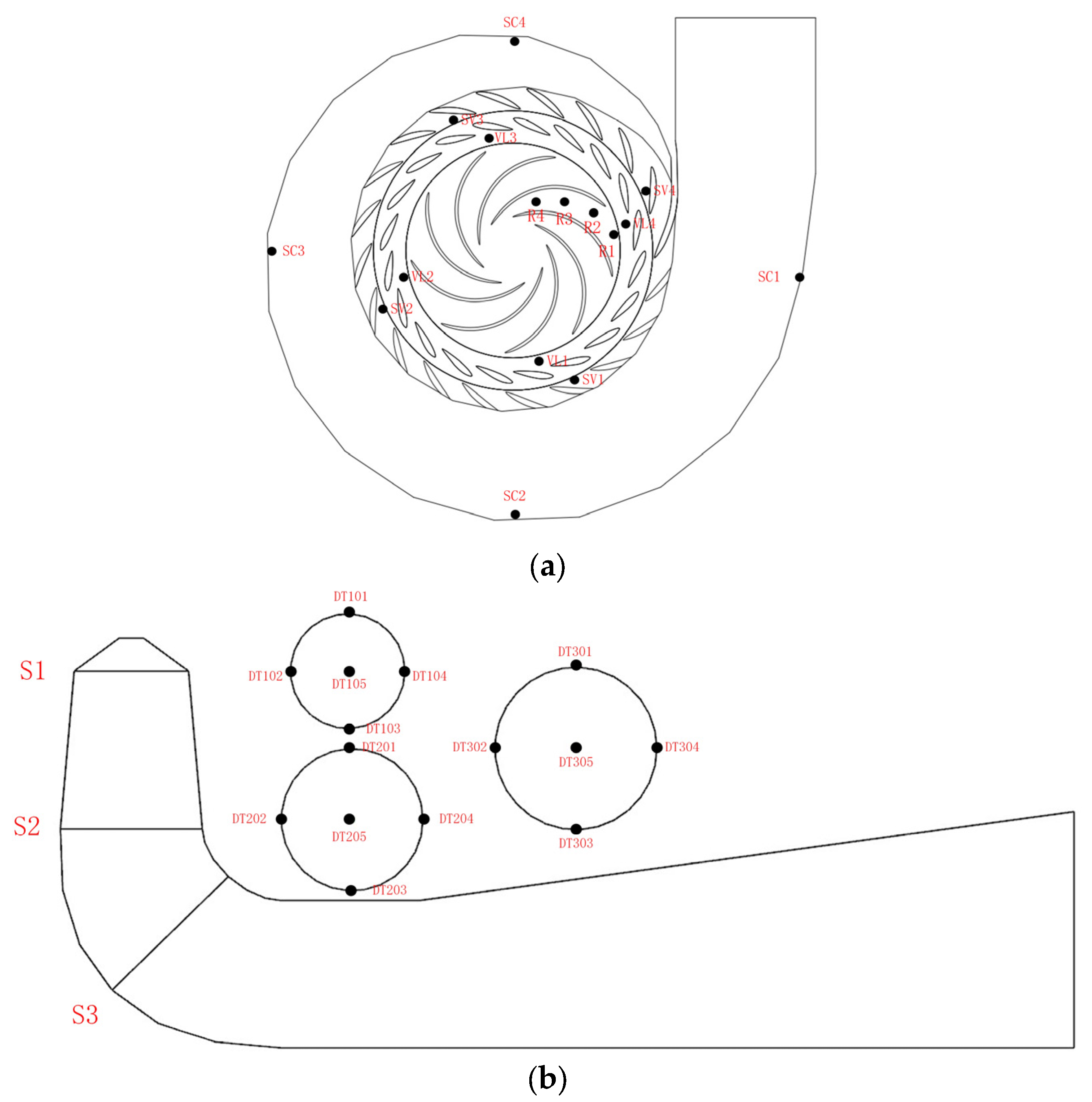
Pressure pulsation is an important parameter reflecting the stable operability of the unit, and its intensity is closely related to the unstable structure within the runner. In order to clarify the change of pressure within each flow-passing part during the speed reduction process, monitor points are set up in each flow passage component and the location is depicted in Figure 13.
In the plane of the middle height of the guide vanes, spiral casing monitor points SC1 to SC4, stay vanes monitor points SV1 to SV4, and vaneless region monitor points VL1 to VL4 are arranged. Along the direction of the runner flow, monitor points R1 to R4 are arranged at the crown of the runner. In the draft tubes, there are three independent reference sections, twelve near-wall monitor points, and three center monitor points were set up. Each wall monitor point was located at a circumferential position 90° apart from each other. Section 1 is located at the inlet, section 2 is located at the end position of the draft tube cone, and section 3 is located at the elbow.
Equation (10) was used to obtain the dimensionless pressure coefficient. The pressure coefficient is used to express the pressure pulsations.
C p = p p ¯ ρ g h
where, p is the transient pressure, Pa; p ¯ is the arithmetic mean value of pressure, Pa; h is the rated head, m; ρ is the water density, kg / m 3 ; g is the gravity, m / s 2 .
In the process of variable speed, the rotational frequency fn and the blade passing frequency 9fn are linearly dependent on the speed, decreasing with the speed.

5.5.1. Spiral Casing

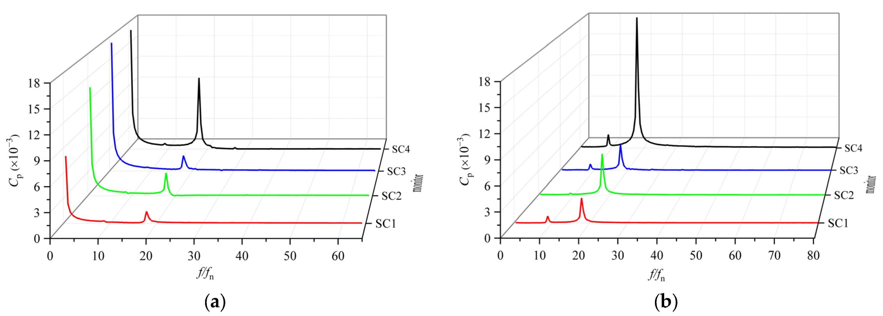
The Fast Fourier transform (FFT) is applied to the transient pressures of the steady state conditions before and after the speed change to obtain the pressure fluctuations in the frequency-domain at each monitor point under these two conditions. The horizontal coordinate f/fn in Figure 14 is the dimensionless frequency ratio, defined as the ratio of the computed frequency f to the rotational frequency fn. It is found that the pressure fluctuations in frequency-domain of the four monitor points in the spiral casing are essentially alike. But the pulsation amplitude of each monitor point from the inlet to the nose of the spiral casing shows an increasing trend, which indicates that the closer the distance to the tongue of the spiral casing, the more it is influenced by the turbulent flow field near the tongue, which leads to a larger pulsation amplitude.
At the rated speed condition, there is a significant low-frequency component of 0.5fn at each monitor point of the spiral casing, while the other frequency such as 18fn is relatively small. After the speed reduction, the low frequency 0.5fn disappears and the amplitude of the 18fn increases. The dominant frequency becomes 18fn, and the secondary frequency is 9fn.
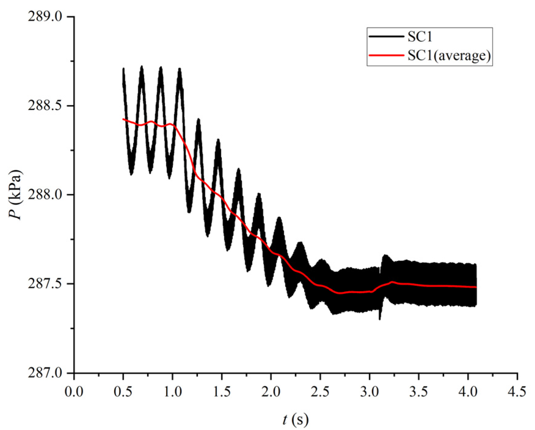
During the whole process of speed change, the pressure of four monitor points in the spiral casing is aligned with the velocity change trend. The transient pressure at the monitor point SC1 of the spiral casing is shown in Figure 15, which is taken after running at the rated speed for 0.5 s. From the figure, it can be seen that in the process of speed reduction, due to the increase of discharge, the velocity inside the spiral casing increases and the pressure decreases. As speed decreases, the amplitude of pressure fluctuations diminishes.
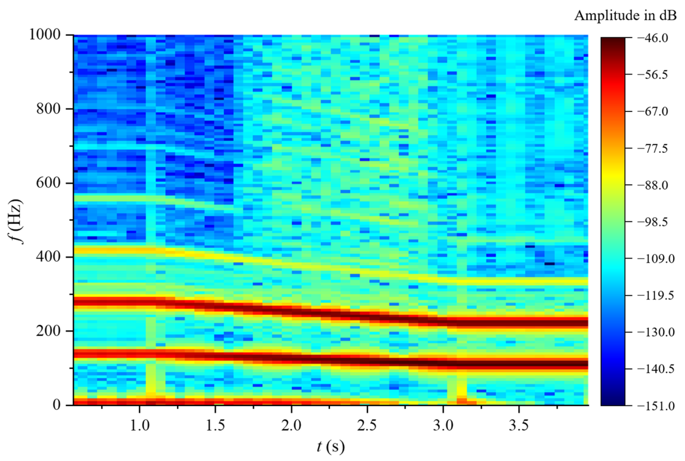
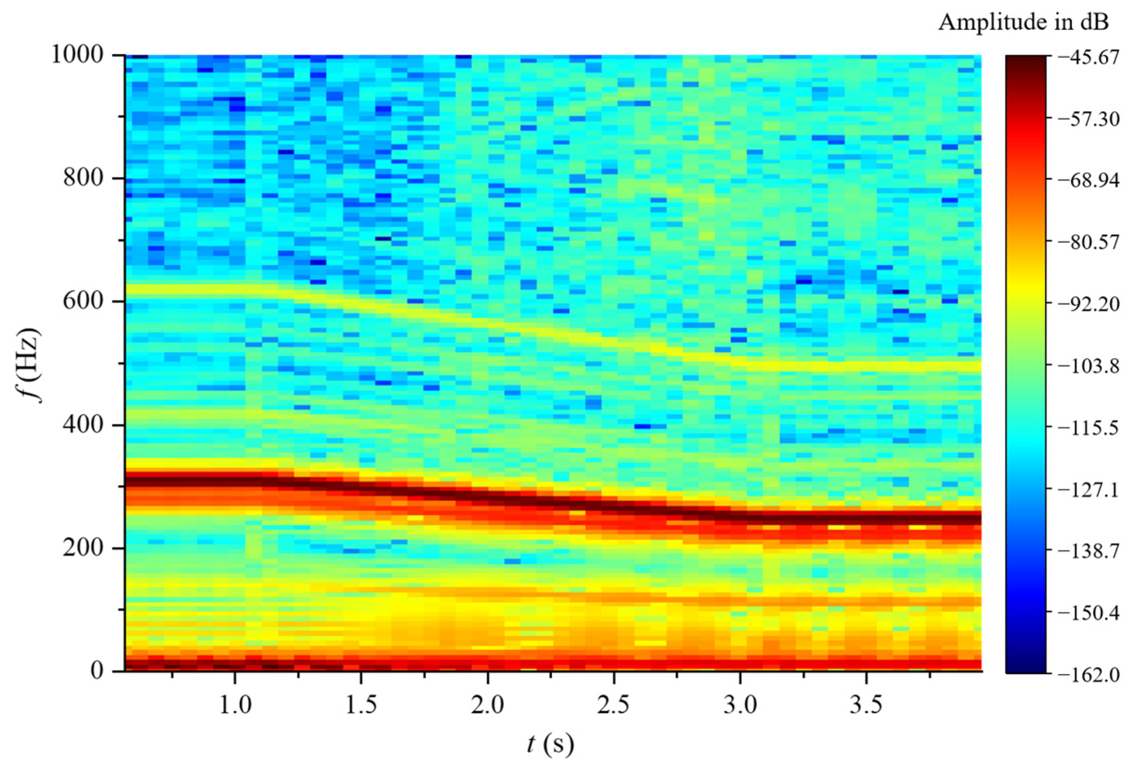
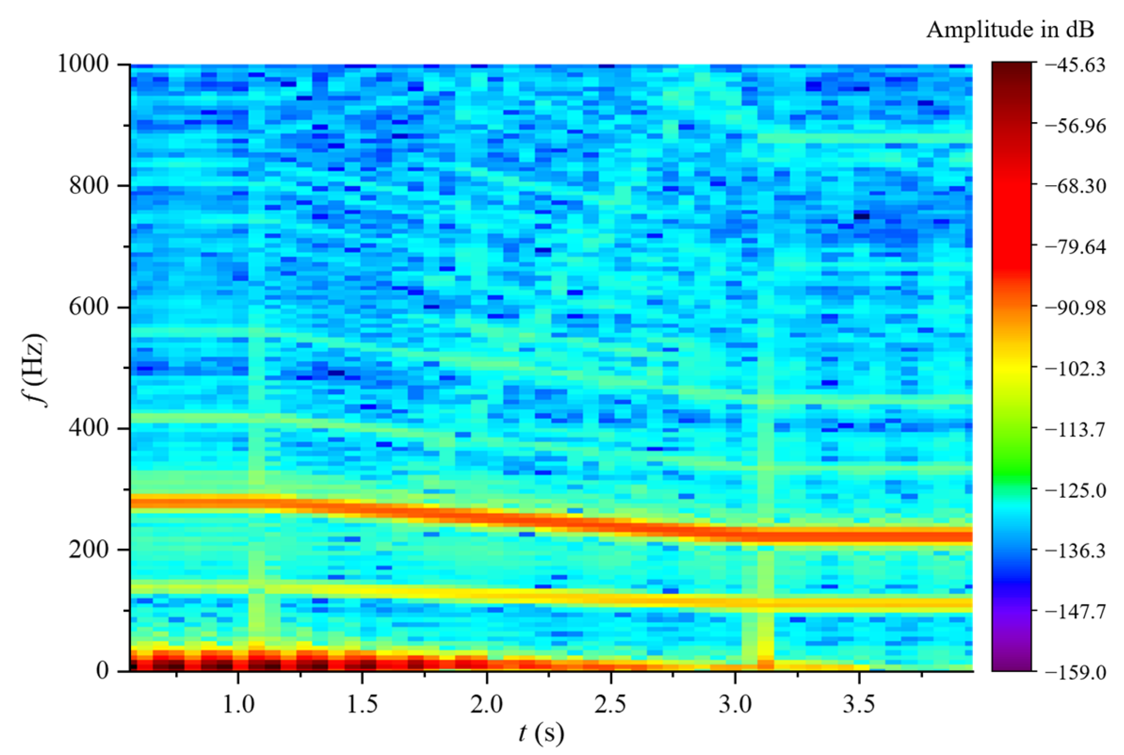
The Short Time FourierTransform (STFT) of the pressure at the monitoring point not only simultaneously displays the correspondence among time, frequency, and amplitude, but also more distinctly illustrates the differences in pressure amplitude at various moments. Figure 16 represents the results. Three frequency bands with higher amplitudes are visible, corresponding to 0.5, 9, and 18 times the rotation frequency, respectively. The amplitude of the 0.5fn is consistent with the speed variation rule, decreasing with the decrease of the speed. It gradually disappears after 2.5 s. The amplitude of the 9fn and 18fn increases with the decrease of speed, but with a small degree of increase.

5.5.2. Stay Vanes

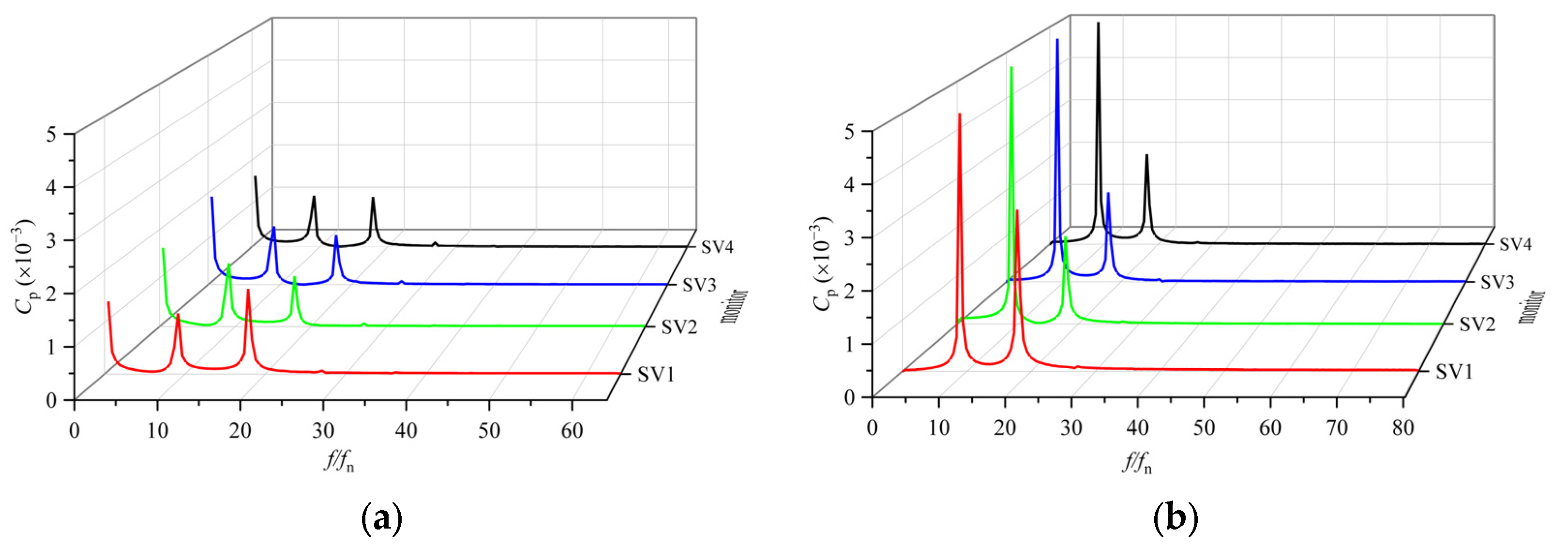
Figure 17 shows that at the rated speed, the dominant frequency is the low frequency 0.5fn and the secondary frequencies are 9fn and 18fn. The difference in amplitude between the dominant and secondary frequencies is small. After the speed change, the low frequency 0.5fn disappears and the amplitude of the 9fn and 18fn increases. The 9fn increases more significantly. At this point the dominant frequency is 9fn and the secondary frequency is 18fn.
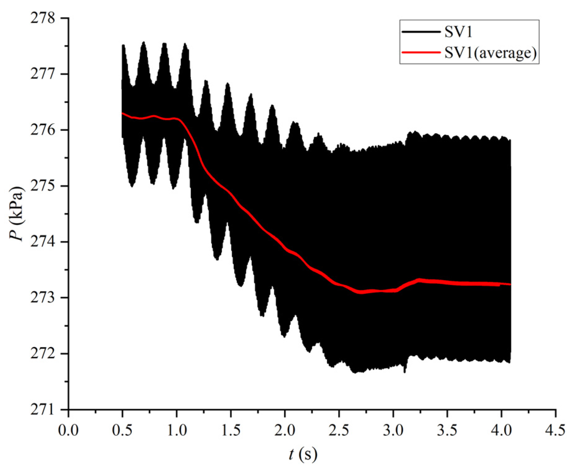
The pressure variation patterns at each measuring point of the stay vanes are basically the same. It is apparent from Figure 18 that as the speed decreases, the pressure at each monitor point decreases, while the amplitude of pressure fluctuation increases.
The STFT result in Figure 19 demonstrates that at the rated speed, the amplitudes of the three frequency bands 0.5fn, 9fn, and 18fn are almost equal. After the speed reduction, the amplitudes of the 9fn and 18fn gradually increase, while the amplitude of the 0.5fn decreases, rapidly decaying and disappearing after 2.5 s.

5.5.3. Vaneless Region

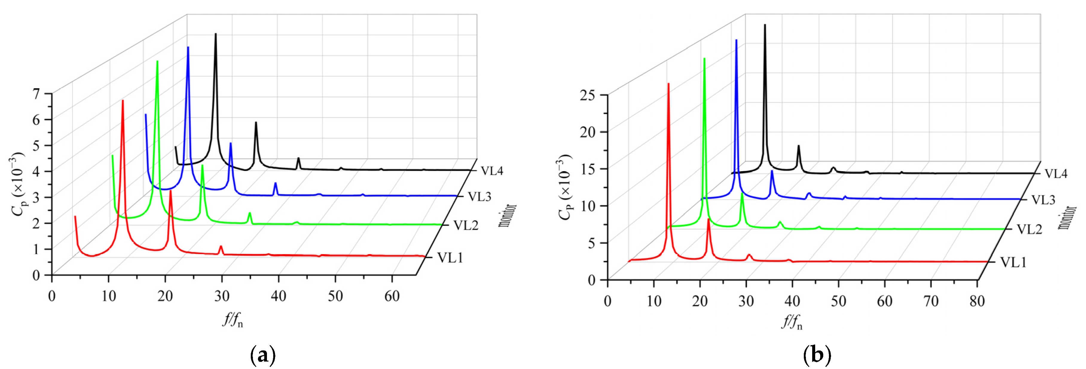
It is clear from Figure 20 that before and after the speed change, the dominant frequency in the vaneless region is the blade passage frequency, i.e., nine times the blade passing frequency 9fn. And the secondary frequency is 18fn, which is two times the blade passing frequency. This indicates that the pressure pulsation in the vaneless region was greatly affected by rotor–stator interference. The amplitude of these two frequencies increases significantly after the speed change, related mainly to the vortex structure formed at the inlet of the runner. The local low pressure caused by the vortex as the runner rotates disturbs the high-pressure flow field in the vaneless region, which will inevitably result in a high amplitude of pressure pulsations in the vaneless region. At the rated speed, there is also a higher amplitude low frequency component of 0.5fn. It is likely to originate mainly from the upstream propagation of the pressure pulsations in the draft tube.
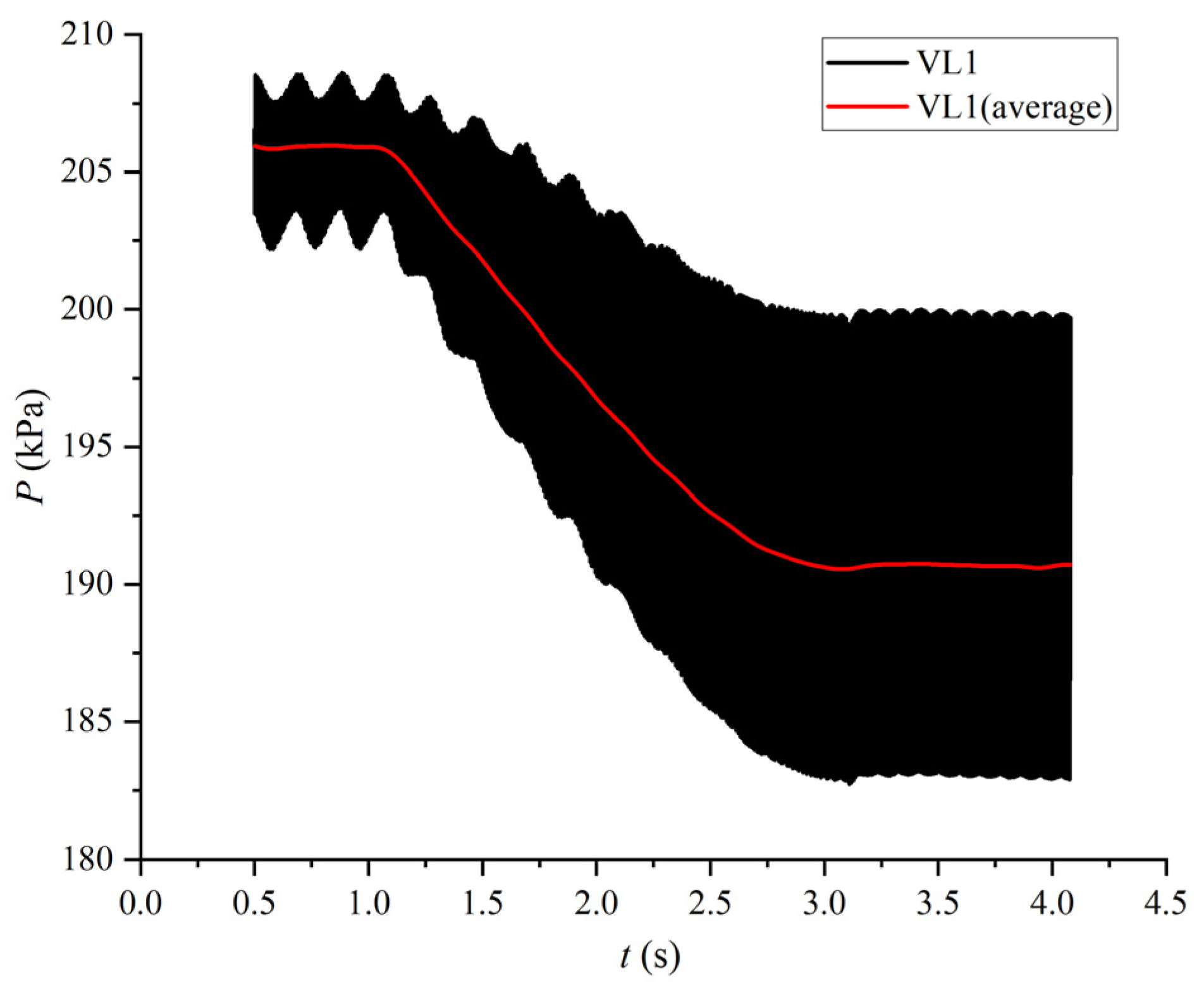
The pressure variation in the vaneless region is shown in Figure 21. In the process of speed reduction, the pressure decreases, while the amplitude of the pressure fluctuation increases. A short-time Fourier transform (STFT) was performed on the pressure at monitor point VL1, and the results are shown in Figure 22. We notice that the pressure has an obvious rotor–stator interference effect, which is manifested in three frequency bands of nine times, 18 times and 27 times the rotational frequency, which is corroborated with the results of the fast Fourier transform (FFT). The amplitude of each frequency band increases with decreasing speed, with the amplitude of the 9fn increasing more significantly.

5.5.4. Runner

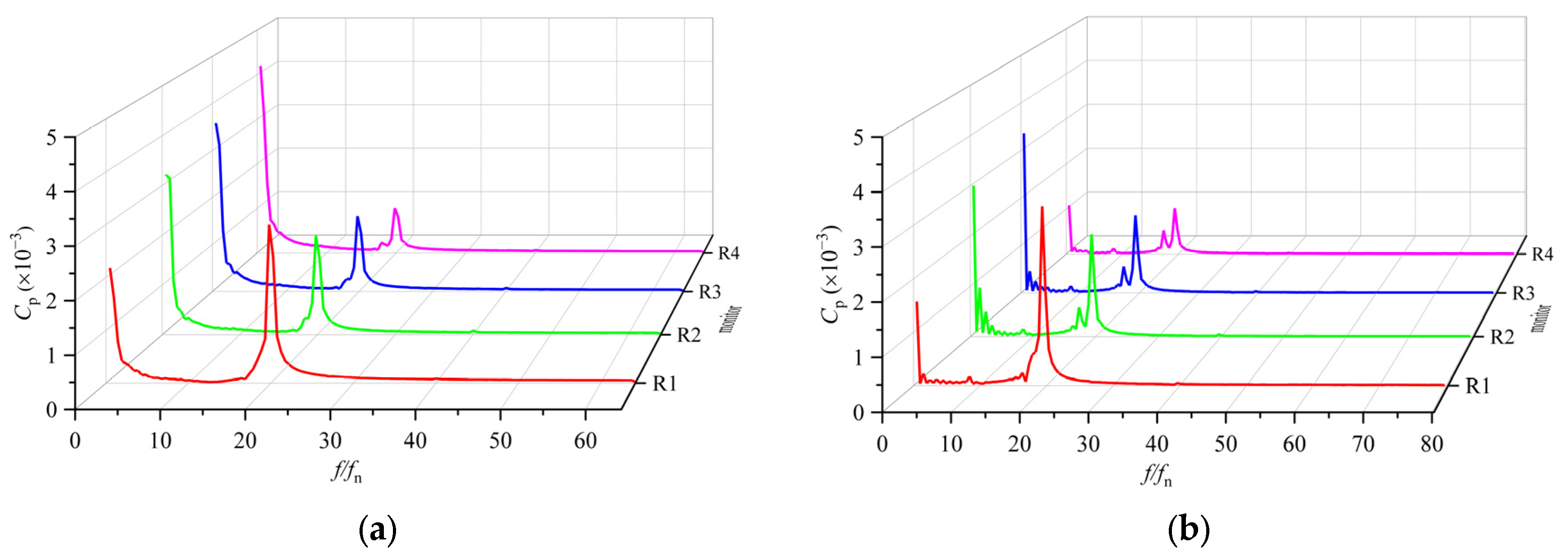
Figure 23 shows that the amplitudes of the two high-amplitude frequencies 0.5fn and 20fn are basically unchanged before and after the speed change, and only the amplitude of the 0.5fn frequency at R4 is different. The amplitude of the frequency at R4 is significantly higher than that after the speed change at the rated condition. This is due to the monitor point being located near the trailing edge of the blade and close to the vortex structure in the draft tube, which greatly affects the pressure pulsation at this monitoring point. The dominant frequency at points R2-R4 is the low frequency 0.5fn and the secondary frequency is 20fn. The amplitude of 0.5fn increases and the amplitude of 20fn decreases with the direction of flow. The pulsation amplitude at the 20fn of the R1 monitoring point is relatively large. This frequency is the guide vane passing frequency. Since the position of this measuring point is relatively close to the head of the runner blade, it is more strongly affected by the dynamic and static interference between the stationary domain and the rotating domain. As a result, the amplitude of the 20fn frequency at the R1 measuring point is higher than that at other measuring points of the same blade.
In this paper, four monitor points, i.e., R1-R4, are taken within the same flow channel. The instantaneous pressure values of each monitor point are shown in Figure 24. It shows that in the same flow channel, the pressure decreases rapidly along the streamwise direction. As the speed decreases, the pressures at the monitor points R1–R3 also diminish. However, the pressure in the vicinity of the runner’s outlet remains essentially stable and shows no decreasing trend. The fluctuation of the pressure at each monitor point does not change significantly.
The Short-Time Fourier Transform of the pressure at monitor point R2 is shown in Figure 25. The change rule of high amplitude pulsation frequency is consistent with the speed. In the process of speed change, the high amplitude 0.5fn decreases, but the range of decrease is small. The amplitude of 20fn is almost unchanged in the process of the speed change. The blade passing frequency 9fn appears after 1.7 s.

5.5.5. Draft Tubes

From Figure 26, it can be seen that at the rated speed, each monitor point induces low-frequency pressure pulsation, corresponding to a dominant frequency of 0.5fn. The amplitude of the pulsation at the monitor point in the center of the draft tube increases gradually with the flow direction. In the draft tube cone, the amplitude of pressure pulsation was higher at the wall than at the center. After the speed change, the low frequency amplitude decreases significantly, and the dominant frequency is 18fn, and the amplitude is also quite small. The pressure pulsation amplitude is almost the same at all monitor points, which is mainly attributed to the shape of the vortex band.
A comparison of pressure pulsations before and after the speed change shows that the amplitude of the low frequency 0.5fn changes significantly. The maximum pressure pulsation coefficient of the 0.5fn is 13.8 × 10⁻³ under the rated condition, while the maximum pressure pulsation coefficient of the 18fn after the speed change is 0.45 × 10⁻³, which indicates that the helical eccentric vortex structure affects the amplitude of pulsation compared with the columnar vortex structure.
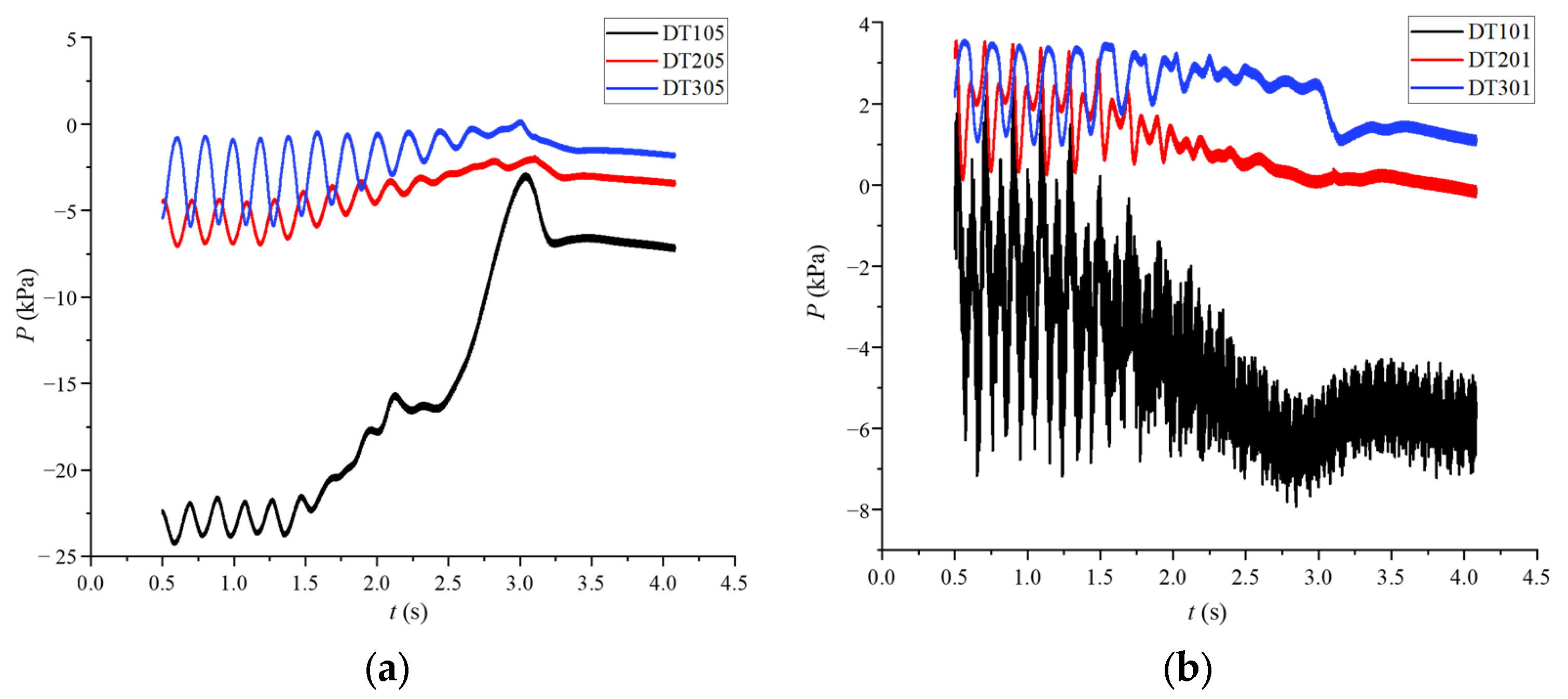
Figure 27 presents the pressure changes on the wall surface and the center of the draft tube in the process of variable speed. It is evident from the figure that the pressure escalates in the flow direction. As the speed declines, the pressure on the wall surface decreases correspondingly, and the pressure pulsation fluctuation is reduced; the pressure at the center increases first and then decreases. Section 1 has a larger magnitude of the pressure change in the monitor point at the center and a larger pressure fluctuation at the wall, compared with the other sections.
Figure 28 shows the STFT results of the pressure at the monitor point DT201. It can be observed from the figure that the low-frequency frequency band of 0.5fn decreases with decreasing speed, and gradually dissipates after 2.5 s. The amplitude of the frequency bands of 9fn and 18fn increases, but the increase is small.

6. Conclusions

This paper focuses on the part-load condition of the turbine operation, with an emphasis on the internal flow characteristics and pressure pulsation characteristics of the pump turbine during the linear reduction of the rated speed. The conclusions are as follows.
(1) When the speed is reduced by 20% from the rated speed, the discharge increases, and the power output and efficiency show the trend of increasing first and then decreasing. It can be concluded that the regulation of power output and efficiency during variable speed is a complex process.
(2) From the rated speed to the optimal efficiency of the corresponding speed, the streamlines between the blades are smooth, and there is no apparent flow separation or vortex. With the reduction of speed, the flow strikes the blade pressure surface at a positive angle of attack, leading to a flow separation at the inlet suction surface of the runner. With the further reduction of speed, the streamlines inside the runner are more turbulent and the vortex scale is further increased.
(3) Under the rated speed conditions with a small guide vane opening, the pump turbine does not run in the optimal operating conditions. At this time the vortex shape displayed in the draft tube is a single helical eccentric vortex structure with high strength. As the speed decreases, the intensity and scope of the vortex rope are weakened until the vortex band disappears. As the speed decreases further, the discharge increases further, the runner outlet circumferential velocity component is opposite to the direction of rotation of the runner, forming a negative flow circulation at the inlet, at which time the vortex structure in the center of the draft tube is shown as a column.
(4) Before the speed change, a high amplitude frequency of 0.5fn exists in each flow-passing part and decreases with the speed reduction. Except for the runner, the amplitudes of 9fn and 18fn of each flow-passing part increase with decreasing speed, especially in the vaneless region, where the increase in the 9fn is most pronounced. This is mainly related to the vortex structure formed in the inlet of the runner. The local low pressure caused by the vortex as the runner rotates disturbs the high-pressure flow field in the vaneless region will inevitably result in a high amplitude of pressure pulsations in the vaneless region. The two high amplitude frequencies in the runner, 0.5fn and 20fn, remain essentially unchanged in amplitude before and after the speed change. With the streamwise of flow in the runner, the guide vanes passing frequency 20fn with decreasing amplitude.

Author Contributions

Conceptualization, G.S. and B.L.; methodology, B.L.; software, X.Y.; validation, G.S., Y.X. and M.T.; formal analysis, B.L.; investigation, M.T.; resources, Y.X.; data curation, B.L.; writing—original draft preparation, B.L.; writing—review and editing, G.S.; visualization, Y.X.; supervision, X.Y.; funding acquisition, G.S. All authors have read and agreed to the published version of the manuscript.

Funding

This research was funded by the Sichuan Natural Science Foundation Outstanding Youth Science Foundation (2024NSFJQ0012); Key project of Regional Innovation and Development Joint Fund of National Natural Science Foundation (U23A20669); Sichuan Science and Technology Program (2022ZDZX0041).

Institutional Review Board Statement

Not applicable.

Informed Consent Statement

Not applicable.

Data Availability Statement

The original contributions presented in this study are included in the article. Further inquiries can be directed to the corresponding author.

Conflicts of Interest

The authors declare no conflicts of interest.

References

  1. Li, J.; Chen, S.; Wu, Y.; Wang, Q.; Liu, X.; Qi, L.; Lu, X.; Gao, L. How to make better use of intermittent and variable energy? A review of wind and photovoltaic power consumption in China. Renew. Sustain. Energy Rev. 2021, 137, 110626. [Google Scholar] [CrossRef]
  2. Hunt, J.D.; Zakeri, B.; Lopes, R.; Barbosa, P.S.F.; Nascimento, A.; de Castro, N.J.; Brandão, R.; Schneider, P.S.; Wada, Y. Existing and new arrangements of pumped-hydro storage plants. Renew. Sustain. Energy Rev. 2020, 129, 109914. [Google Scholar] [CrossRef]
  3. Javed, S.M.; Ma, T.; Jurasz, J.; Armin, M.Y. Solar and wind power generation systems with pumped hydro storage: Review and future perspectives. Renew. Energy 2020, 148, 176–192. [Google Scholar] [CrossRef]
  4. Sun, K.; Li, K.-J.; Pan, J.; Liu, Y.; Liu, Y. An optimal combined operation scheme for pumped storage and hybrid wind-photovoltaic complementary power generation system. Appl. Energy 2019, 242, 1155–1163. [Google Scholar] [CrossRef]
  5. Abdelfattah, A.I.; Shaaban, M.F.; Osman, A.H.; Ali, A. Optimal Management of Seasonal Pumped Hydro Storage System for Peak Shaving. Sustainability 2023, 15, 11973. [Google Scholar] [CrossRef]
  6. Suh, J.-W.; Kim, S.-J.; Kim, J.-H.; Joo, W.-G.; Park, J.; Choi, Y.-S. Effect of interface condition on the hydraulic characteristics of a pump-turbine at various guide vane opening conditions in pump mode. Renew. Energy 2020, 154, 986–1004. [Google Scholar] [CrossRef]
  7. Yu, A.; Wang, Y.; Tang, Q.; Lv, R.; Yang, Z. Investigation of the vortex evolution and hydraulic excitation in a pump-turbine operating at different conditions. Renew. Energy 2021, 171, 462–478. [Google Scholar] [CrossRef]
  8. Shi, G.; Hao, Z.; Peng, X.; Wen, H.; Lv, W.; Fu, J. Analysis of vortex characteristics in the S-shaped region of a reversible Pump-Turbine with different guide vane openings based on Omega vortex identification method. J. Energy Storage 2024, 84, 110921. [Google Scholar] [CrossRef]
  9. Yao, W.; Deng, C.; Li, D.; Chen, M.; Peng, P.; Zhang, H.; Yao, W.; Deng, C.; Li, D.; Chen, M.; et al. Optimal Sizing of Seawater Pumped Storage Plant with Variable-Speed Units Considering Offshore Wind Power Accommodation. Sustainability 2019, 11, 1939. [Google Scholar] [CrossRef]
  10. Iliev, I.; Trivedi, C.; Dahlhaug, O.G. Variable-speed operation of Francis turbines: A review of the perspectives and challenges. Renew. Sustain. Energy Rev. 2019, 103, 109–121. [Google Scholar] [CrossRef]
  11. Bidgoli, M.A.; Yang, W.J.; Ahmadian, A. DFIM versus synchronous machine for variable speed pumped storage hydropower plants: A comparative evaluation of technical performance. Renew. Energy 2020, 159, 72–86. [Google Scholar] [CrossRef]
  12. Gao, C.; Yu, X.; Nan, H.; Men, C.; Fu, J. A Fast High-Precision Model of the Doubly-Fed Pumped Storage Unit. J. Electr. Eng. Technol. 2021, 16, 797–808. [Google Scholar] [CrossRef]
  13. Vasudevan, K.R.; Ramachandaramurthy, V.K.; Venugopal, G.; Ekanayake, J.B.; Tiong, S.K. Variable speed pumped hydro storage: A review of converters, controls and energy management strategies. Renew. Sustain. Energy Rev. 2021, 135, 11156. [Google Scholar] [CrossRef]
  14. Zhu, K.K.; Ruan, L. Self-starting control strategy of variable speed pumped storage unit based on adaptive full order state observer. Meas. Control 2023, 56, 630–637. [Google Scholar] [CrossRef]
  15. Deng, Y.; Wang, P.; Morabito, A.; Feng, W.; Mahmud, A.; Chen, D.; Hendrick, P. Dynamic analysis of variable-speed pumped storage plants for mitigating effects of excess wind power generation. Int. J. Electr. Power Energy Syst. 2022, 135, 107453. [Google Scholar] [CrossRef]
  16. Huang, Y.; Yang, W.; Zhao, Z.; Han, W.; Li, Y.; Yang, J. Dynamic modeling and favorable speed command of variable-speed pumped-storage unit during power regulation. Renew. Energy 2023, 206, 769–783. [Google Scholar] [CrossRef]
  17. Heckelsmueller, G.P. Application of variable speed operation on Francis turbines. Ing. Investig. 2015, 35, 12–16. [Google Scholar] [CrossRef]
  18. Bortoni, E.; Souza, Z.d.; Viana, A.; Villa-Nova, H.; Rezek, Â.; Pinto, L.; Siniscalchi, R.; Bragança, R.; Bernardes, J., Jr. The Benefits of Variable Speed Operation in Hydropower Plants Driven by Francis Turbines. Energies 2019, 12, 3719. [Google Scholar] [CrossRef]
  19. Yu, Z.-F.; Wang, W.-Q.; Yan, Y.; Wang, H.-Y.; Wu, W.-L. Evaluating energy-efficiency improvement of variable-speed operation with the help of entropy: A case study of low-head Francis turbine. Sustain. Energy Technol. Assess. 2022, 53, 102468. [Google Scholar] [CrossRef]
  20. Feng, C.; Li, C.; Chang, L.; Ding, T.; Mai, Z. Advantage analysis of variable-speed pumped storage units in renewable energy power grid: Mechanism of avoiding S-shaped region. Int. J. Electr. Power Energy Syst. 2020, 120, 105976. [Google Scholar] [CrossRef]
  21. Deng, W.; Xu, L.; Li, Z.; Tang, W.; Wang, X.; Shang, L.; Liu, D.; Liu, X. Stability Analysis of Vaneless Space in High-Head Pump-Turbine under Turbine Mode: Computational Fluid Dynamics Simulation and Particle Imaging Velocimetry Measurement. Machines 2022, 10, 143. [Google Scholar] [CrossRef]
  22. Lai, X.; Chen, X.; Liang, Q.; Ye, D.; Gou, Q.; Wang, R.; Yan, Y. Experimental and numerical investigation of vortex flows and pressure fluctuations in a high-head pump-turbine. Renew. Energy 2023, 211, 236–247. [Google Scholar] [CrossRef]
  23. Cheng, H.; Zhou, L.; Liang, Q.; Guan, Z.; Liu, D.; Wang, Z.; Kang, W. A method of evaluating the vortex rope strength in draft tube of Francis turbine. Renew. Energy 2020, 152, 770–780. [Google Scholar] [CrossRef]
  24. Zhu, D.; Yan, W.; Guang, W.; Wang, Z.; Tao, R. Influence of Guide Vane Opening on the Runaway Stability of a Pump-Turbine Used for Hydropower and Ocean Power. J. Mar. Sci. Eng. 2023, 11, 1218. [Google Scholar] [CrossRef]
  25. Trivedi, C.; Agnalt, E.; Dahlhaug, O.G. Experimental study of a Francis turbine under variable-speed and discharge conditions. Renew. Energy 2018, 119, 447–458. [Google Scholar] [CrossRef]
  26. Trivedi, C.; Agnalt, E.; Dahlhaug, O.G. Investigations of unsteady pressure loading in a Francis turbine during variable-speed operation. Renew. Energy 2017, 113, 397–410. [Google Scholar] [CrossRef]
  27. Rode, B.R.; Kumar, A. Rotor-stator interaction investigations in variable speed reversible pump-turbine at higher head. Phys. Fluids 2024, 36, 035122. [Google Scholar] [CrossRef]
  28. Shang, L.; Cao, J.; Wang, L.; Yu, S.; Ding, S.; Wei, Z.; Wang, Z.; Liu, X. Analysis of Flow and Runner Dynamic Response Characteristics under Pump Conditions of Variable-Speed Pump Turbine. J. Mar. Sci. Eng. 2023, 11, 1493. [Google Scholar] [CrossRef]
  29. Li, Y.; Yang, W.; Huang, Y.; Ma, W.; Zhao, Z.; Yang, J.; Cheng, Y.; Qian, Z.; Yang, J. Reduction of Pressure Pulsation for Pump-Turbine by Variable Speed Operation. J. Energy Resour. Technol.-Trans. ASME 2023, 145, 081301. [Google Scholar] [CrossRef]
  30. Trivedi, C.; Iliev, I.; Dahlhaug, O.G.; Markov, Z.; Engstrom, F.; Lysaker, H. Investigation of a Francis turbine during speed variation: Inception of cavitation. Renew. Energy 2020, 166, 147–162. [Google Scholar] [CrossRef]
  31. Lv, Y.; Li, S.G.; Wang, Z.W.; Zhou, L.J. Study on pump mode cavitation characteristic of variable speed pump turbine. Phys. Fluids 2023, 35, 065111. [Google Scholar]
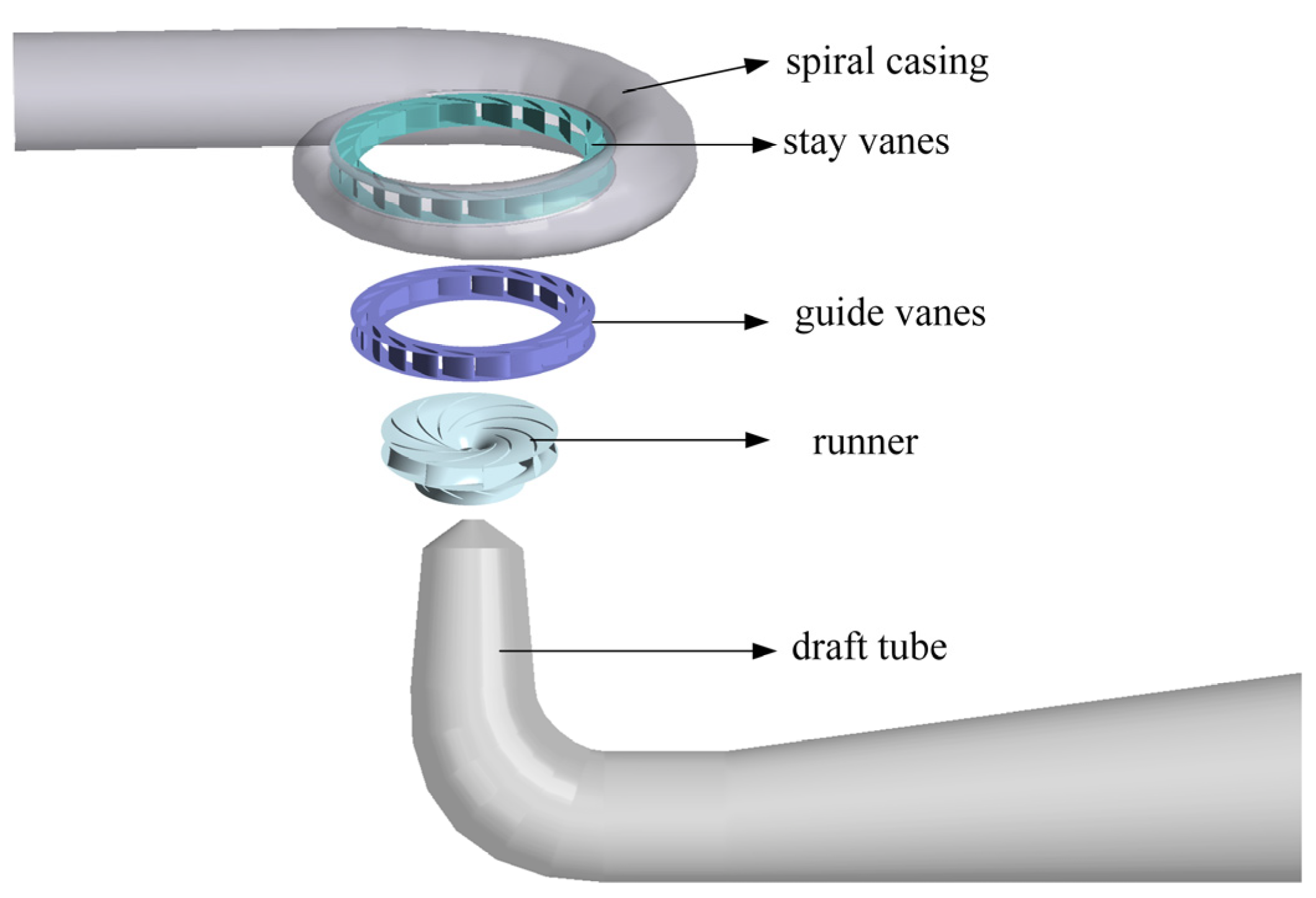
Figure 1. 3D Model of pump turbine.
Jmse 12 02243 g001
Figure 2. Computational domain mesh of a pump-turbine.
Jmse 12 02243 g002
Figure 3. Y+ distribution of runner.
Jmse 12 02243 g003
Figure 4. Mesh independence verification.
Jmse 12 02243 g004
Figure 5. Performance curves of simulation and experiment.
Jmse 12 02243 g005
Figure 6. External characteristic curve during speed variation.
Jmse 12 02243 g006
Figure 7. Distribution of streamline in the runner in the process of speed change.
Jmse 12 02243 g007
Figure 8. Velocity triangles at impeller inlet.
Jmse 12 02243 g008
Figure 9. Eliminating the effect of the wall of the draft tube cone identified by the Q-criterion.
Jmse 12 02243 g009
Figure 10. Changes of vortex rope during variable speed.
Jmse 12 02243 g010
Figure 11. Velocity triangles at impeller outlet.
Jmse 12 02243 g011
Figure 12. Axial velocity cloud and velocity vector in draft tube.
Jmse 12 02243 g012
Figure 13. Distribution of monitor points. (a) Distribution of monitor points in the Spiral casing, stay vanes, vaneless area and runner. (b) Distribution of monitor points in the draft tube.
Jmse 12 02243 g013
Figure 14. Frequency-domain plots of pressure pulsation before and after speed change at each monitor point of spiral casing. (a) pressure fluctuations in frequency-domain at the rated speed. (b) pressure fluctuations in frequency-domain after a speed change.
Jmse 12 02243 g014
Figure 15. Pressure variation, SC1.
Jmse 12 02243 g015
Figure 16. Spectrogram of fluctuating pressure signal throughout variable speed process, SC1.
Jmse 12 02243 g016
Figure 17. Frequency-domain plots of pressure pulsation before and after the change of speed at each monitor point of stay vanes. (a) pressure fluctuations in frequency-domain at the rated speed. (b) pressure fluctuations in frequency-domain after the speed change.
Jmse 12 02243 g017
Figure 18. Pressure variation, SV1.
Jmse 12 02243 g018
Figure 19. Spectrogram of fluctuating pressure signal throughout variable speed process, SV1.
Jmse 12 02243 g019
Figure 20. Frequency-domain plots of pressure pulsation before and after the change of speed at each monitor point of vaneless region. (a) pressure fluctuations in frequency-domain at the rated speed. (b) pressure fluctuations in frequency-domain after speed change.
Jmse 12 02243 g020
Figure 21. Pressure variation, VL1.
Jmse 12 02243 g021
Figure 22. Spectrogram of fluctuating pressure signal throughout variable speed process, VL1.
Jmse 12 02243 g022
Figure 23. Frequency-domain plots of pressure pulsation before and after the change of speed at each monitor point of runner. (a) pressure fluctuations in frequency-domain at the rated speed. (b) pressure fluctuations in frequency-domain after speed change.
Jmse 12 02243 g023
Figure 24. Pressure variation at each monitor point of the runner.
Jmse 12 02243 g024
Figure 25. Spectrogram of fluctuating pressure signal throughout variable speed process, R2.
Jmse 12 02243 g025
Figure 26. Frequency-domain plots of pressure pulsation before and after the change of speed at some monitor point of draft tube. (a) pressure fluctuations in frequency-domain at the rated speed. (b) pressure fluctuations in frequency-domain after speed change.
Jmse 12 02243 g026
Figure 27. Pressure variation at some monitor points of the draft tube. (a) Pressure variation, DT105, DT205 and DT305. (b) Pressure variation, DT101, DT201 and DT301.
Jmse 12 02243 g027
Figure 28. Spectrogram of fluctuating pressure signal throughout variable speed process, DT201.
Jmse 12 02243 g028
Table 1. Basic parameters of pump turbine.
ParametersSymbolsValues
Diameter of impeller inletD1470 mm
Diameter of impeller outletD2300 mm
Number of stay vanesZS20
Number of guide vanesZg20
Number of impeller bladesZr9
Guide vane openinga19 mm
HeadH30 m
Rated speedn1931.128 r/min
Disclaimer/Publisher’s Note: The statements, opinions and data contained in all publications are solely those of the individual author(s) and contributor(s) and not of MDPI and/or the editor(s). MDPI and/or the editor(s) disclaim responsibility for any injury to people or property resulting from any ideas, methods, instructions or products referred to in the content.