Article

Wave-Induced Instantaneous Liquefaction of a Non-Cohesive Seabed around Buried Pipelines: A Liquefaction-Associated Non-Darcy Flow Model Approach

1
Key Laboratory for Urban Underground Engineering of the Ministry of Education, Beijing Jiaotong University, Beijing 100044, China
2
Key Laboratory for Mechanics in Fluid Solid Coupling Systems, Institute of Mechanics, Chinese Academy of Sciences, Beijing 100190, China
3
School of Engineering Science, University of Chinese Academy of Sciences, Beijing 100049, China
*
Author to whom correspondence should be addressed.
J. Mar. Sci. Eng. 2024, 12(3), 373; https://doi.org/10.3390/jmse12030373
Submission received: 18 January 2024 / Revised: 16 February 2024 / Accepted: 19 February 2024 / Published: 22 February 2024

Abstract

:
In complex marine environments, the wave-induced instantaneous liquefaction of the seabed is a key issue for the long-term safety control of marine structures. Existing computational frameworks for instantaneous liquefaction result in unreasonable tensile stresses in a non-cohesive seabed. To address this issue, a liquefaction-associated non-Darcy flow model has been proposed, but it has only been applied to the scenario of a pure seabed without a structure. In this study, we applied the previously proposed non-Darcy flow model to investigate the mechanism of wave–seabed–structure interactions under extreme wave loading considering a pipeline fully buried in a non-cohesive seabed. By comparing the liquefaction depths in the presence and absence of structures, it was found that the existence of structures weakens the attenuation of the pore pressure amplitude and influences the overall pore pressure distribution. Parametric studies were conducted. It was found that the liquefaction depth from the non-Darcy model is approximately 0.73 times that from the traditional Darcy model, regardless of whether or not a pipeline is involved. A quantitative relationship between the wave loading and structural size was established. The liquefied zone above the buried pipeline was found to be smaller than that in a pure seabed without a structure. A tentative explanation is provided for this phenomenon.

1. Introduction

In the wave-dominated coastal zone, the wave-induced liquefaction of the seabed often occurs due to the propagation of waves inducing excess pore pressure within the seabed, leading to a decrease in effective stress. Seabed liquefaction has a close relation with the erosion or resuspension of marine sediment [1,2,3,4,5] and can affect the stability of coastal structures [6,7]. Therefore, it has become a key concern within the scope of marine engineering. Based on laboratory experiments and field measurements [8,9], wave-induced seabed liquefaction can be categorized into instantaneous liquefaction and residual liquefaction, induced by instantaneous pore pressure and residual pore pressure, respectively. This study focuses on the instantaneous liquefaction occurring in a non-cohesive seabed.
In this scenario, the behavior of the non-cohesive seabed can be described using the pore-elasticity assumption for the following reasons. After the occurrence of instantaneous liquefaction, the soil becomes loose, and then it rearranges into a dense state through wave-induced compaction or consolidation. This results in subsequent wave-induced seabed responses following a “reloading–unloading” pattern [7,10,11]. For the case of a pure seabed without a structure, several analytical solutions have been developed under various conditions [12,13,14,15]. However, for a seabed including structures such as submarine pipelines [16,17,18,19,20,21,22,23,24,25,26], breakwaters [27,28,29], coastal slopes [30], offshore wind turbine foundations [31,32,33,34,35,36,37], gravity-based structure (GBS) offshore platforms [38], dumbbell-shaped cofferdams [39], and immersed tunnels [40,41], the presence of the structures complicates the boundary conditions, generally requiring numerical methods for analyses. Recently, Li et al. [42] developed an open-source numerical toolbox for simulating the interaction between a porous seabed, waves, and structures. This toolbox greatly enhances the efficiency of research on wave–seabed–structure interactions. When marine structures undergo rocking motion under external forces, additional excess pore pressure can be induced [43,44,45,46]. It has also been found that marine structures can exhibit the phenomenon of principal stress rotation [47,48]. Furthermore, nonlinear contact behavior at the interface between the structure and seabed should also be considered [49]. These scenarios have been extensively analyzed in previous studies.
However, the existing computational methods and analytical models associated with instantaneous liquefaction can result in unreasonable tensile stresses in a non-cohesive seabed [50,51]. This nonphysical phenomenon further influences the overall distribution of pore pressure [50,51]. In fact, when instantaneous liquefaction occurs in a non-cohesive seabed, the physical and mechanical parameters of the seabed should change accordingly. However, most existing models employ an invariant poro-elastic assumption [14,35].
In order to eliminate unreasonable tensile behavior, Zhou et al. [52] was inspired by the literature [53,54] and introduced a dynamic permeability model. This model uses soil permeability k s that is determined by pore pressure p instead of the constant permeability assumed in conventional Darcy’s law. This treatment mitigates the occurrence of unrealistic tensile stresses in the liquefaction zone. Compared with the previous dynamic permeability models [53,54], the new model built by Zhou et al. [52] agrees with the concept of an increase in permeability during soil liquefaction [55,56,57,58,59,60]. However, this model [52] faces challenges in nonlinear convergence. When using larger model parameters or finer computational grids, numerical divergence may even occur, limiting its applications. Therefore, Zhou et al. [61] further converted the instantaneous liquefaction problem into a mathematical problem, i.e., a nonlinear complementarity problem (NCP). They employed specific Karush–Kuhn–Tucker (KKT) conditions for instantaneous liquefaction and a Lagrange multiplier method to solve the problem, while they optimized it using the primal-dual active set strategy (PDASS) [62]. Additionally, they improved computational efficiency by employing direct delta function interpolation to condense the multipliers. This method addresses the challenge of nonlinear convergence caused by the previous dynamic permeability model [52]. However, solving the NCP problem falls within the scope of a constrained variational theory framework and is not a standard module in most finite element codes (such as PORO-FSSI-FOAM [20,21]). Applying the NCP approach to broader scenarios, such as pipelines that are partially buried in the seabed [16,23], gravity foundations for offshore wind turbines [32], and monopile foundations [33,35], is also not convenient.
Recently, Zhou et al. [63] proposed a new KKT condition for wave-induced instantaneous liquefaction through the variational equivalence principle; thus, a non-Darcy flow model was proposed for instantaneous liquefaction. This model not only eliminates the phenomenon of tensile stress in the liquefied zone but also provides significant convenience for numerical implementations, because only the formulation of a seepage constitutive equation is required to be incorporated into finite element codes. Furthermore, it provides a unified explanation for various existing phenomena, such as non-cohesive granular soils with an upward seepage flow [64]; experimental results on piping in sandy gravels [65]; field trials [3]; and DEM-PFV simulations [66]. However, these works were still limited to the scenario of wave–seabed interactions without a structure.
In this work, we further took into account a pipeline fully buried in a non-cohesive seabed under wave loadings in order to investigate wave–seabed–structure interactions with the use of our non-Darcy flow model [63]. First, we extended our previous finite element code to a scenario that can consider a structure fully buried in the seabed. This extension was validated by comparing our numerical results with the experimental results of Turcotte [67]. Then, a computational example under extreme wave loading was conducted to compare the liquefaction depths in the presence and absence of structures. Parametric studies were further accomplished considering wave, seabed, and structural parameters. Non-dimensional parametric studies were also carried out.
The remainder of this paper is as follows. Section 2 provides a brief overview of the fundamental theory and governing equations of the non-Darcy flow model considering a fully buried structure. In Section 3, the wave–seabed–structure model is validated based on classical experimental results without liquefaction. Section 4 presents the numerical results under extreme wave loading conditions, which induce seabed liquefaction. A quantitative relationship between the wave loading and structural response is exploited. Section 5 tries to provide an explanation for the liquefaction phenomenon in a seabed including a buried structure. Finally, Section 6 draws several conclusions.

2. The Liquefaction-Associated Non-Darcy Flow Model

2.1. Wave–Seabed–Structure Model and Liquefaction Criteria

Figure 1 depicts the wave–seabed–structure model and the process of seabed liquefaction, where 𝑑t represents the thickness of the seabed, h represents the water depth, and 𝐻 represents the wave height. The coordinate value on the seabed surface is 0, and positive values exist below the seabed. Ω L denotes the zones in the seabed where instantaneous liquefaction occurs. During the process of wave loading, when the soil is located at or near a wave trough, the wave-induced seepage force is upward. When the upward seepage force equals the initial vertical effective stress of the seabed soil, the effective stress of the soil becomes zero, leading to an instantaneous liquefaction state. It should be noted that the wave in Figure 1 is linear. If considering nonlinear waves, Stokes waves [17] or cnoidal waves [68] should be employed. To simplify the model, this study applies linear wave theory [69]:
P b = p 0 cos 2 π L x 2 π L t ,
where P b , whose amplitude is represented by p 0 , represents the wave pressure acting on the seabed surface (z = 0). L denotes the wavelength, while T denotes the wave period. The values of p 0 and L can be calculated by the following equations:
p 0 = γ w H 2 cosh 2 π h / L ,   L = g T 2 2 π tanh 2 π h L ,
where γ w denotes the unit weight of water, while g represents the acceleration of gravity. The governing equations of the wave–seabed–structure model are as follows:
σ p I 2 × 2 + b = 0   in   Ω   ,
ε v t + n β p t k s γ w p = 0 in Ω   ,
u = u ^ on Γ u   ,
σ n σ = t ^ on Γ σ   ,
p = p ^ on Γ p   ,
v w n v = v ^ w n on Γ v   ,
The first two equations are derived from the theory of poro-elasticity theory [70]. Equation (3a) denotes the equilibrium of the solid–fluid mixture, in which σ represents the effective stress, Ι 2 × 2 denotes the second-order unit tensor, and b denotes the body force per unit volume. Equation (3b) denotes the conservation of mass, in which ε v represents the volumetric strain, t represents time, k s is Darcy’s coefficient of permeability, and β represents the pore-fluid compressibility, which is determined by [71]
β = 1 K w 0 + 1 S r P a b s ,
where K w 0 represents the true bulk modulus of pore water, which can be taken as 2.0 × 10⁹ Pa [14]. S r denotes the degree of saturation, while P a b s represents the hydrodynamic pressure of water. The remaining expressions in Equation (3c–f) denote boundary conditions. Γ u and Γ σ denote two boundaries of the solid phase, where Γ u represents the Dirichlet boundary and Γ σ represents the Neumann boundary, while Γ p and Γ v denote two boundaries of the fluid phase, where Γ p represents the Dirichlet boundary and Γ v represents the Neumann boundary. In Equation (3c), u represents the vector of displacement, while u ^ denotes the displacement that is constrained. In Equation (3d), σ denotes the tensor of total stress, n σ denotes the unit normal vector pointing outward from Γ σ , and t ^ denotes the surface force per unit area acting on the boundary. In Equation (3e), p ^ represents the pore pressure. In Equation (3f), v w denotes the vector of pore-fluid velocity, n v denotes the unit normal vector pointing outward from Γ v , and v ^ w n represents the boundary Darcy velocity.
It should be noted that the research presented in this paper aims to extend the non-Darcy flow model from pure seabed scenarios without structures to scenarios with structures. The presence of a structure in the seabed implies increased boundary conditions compared to the pure seabed. In order to simplify the computational model, the boundary condition around the structure is considered an impermeable boundary, corresponding to Equation (3), where v ^ w n is taken as zero.
When the seabed experiences instantaneous liquefaction, there are two widely applied liquefaction criteria for determining the liquefaction zone ( Ω L ), which use the tensile region of the sandy soil as the liquefaction zone:
p P b γ z ,
j z γ ,
where p is the excessive pore pressure caused by waves. Its gradient along the vertical direction is expressed as j z = p / z . γ denotes the buoyant unit weight of the seabed and obeys the following expression: γ = G s 1 1 n γ w , where G s represents the specific gravity of sand particles, and n represents the porosity of the sand, which is related to the void ratio e: n = e / 1 + e .

2.2. Numerical Implementation of the Non-Darcy Flow Model

In general, the liquefaction zone may vary based on the aforementioned two liquefaction criteria. Qi and Gao’s [51] research revealed that, in Equations (5) and (6), the parts where p – Pb > γz and jz > γ′ represent the presence of tensile stress in the non-cohesive seabed. This is obviously nonphysical and leads to the inconsistency in liquefaction zones predicted by the two criteria. Therefore, when liquefaction occurs, even if the wave height continues to increase, the inequality signs in Equations (5) and (6) should always be equal signs. Thus, we revised Equations (5) and (6) as follows, respectively:
p P b γ z
j z γ
By introducing Equation (8) as an additional constraint to Equation (3), Equation (3) can be rewritten as follows:
σ p I 2 × 2 + b = 0   in   Ω   ,
ε v t + n β p t v w = 0 in Ω   ,
u = u ^ on Γ u   ,
σ n σ = t ^ on Γ σ   ,
p = p ^ on Γ p   ,
v w n v = v ^ w n on Γ v   ,
where the pore-fluid velocity v w is determined by
v w x = k s γ w p x ,   v w z = k s γ w p z κ p z γ ,
where v w x and v w z represent the horizontal and vertical components of v w , respectively. κ is the penalty factor and makes Darcy’s law hold in the horizontal direction, while the significant nonlinearity caused by seabed liquefaction appears in the vertical direction.
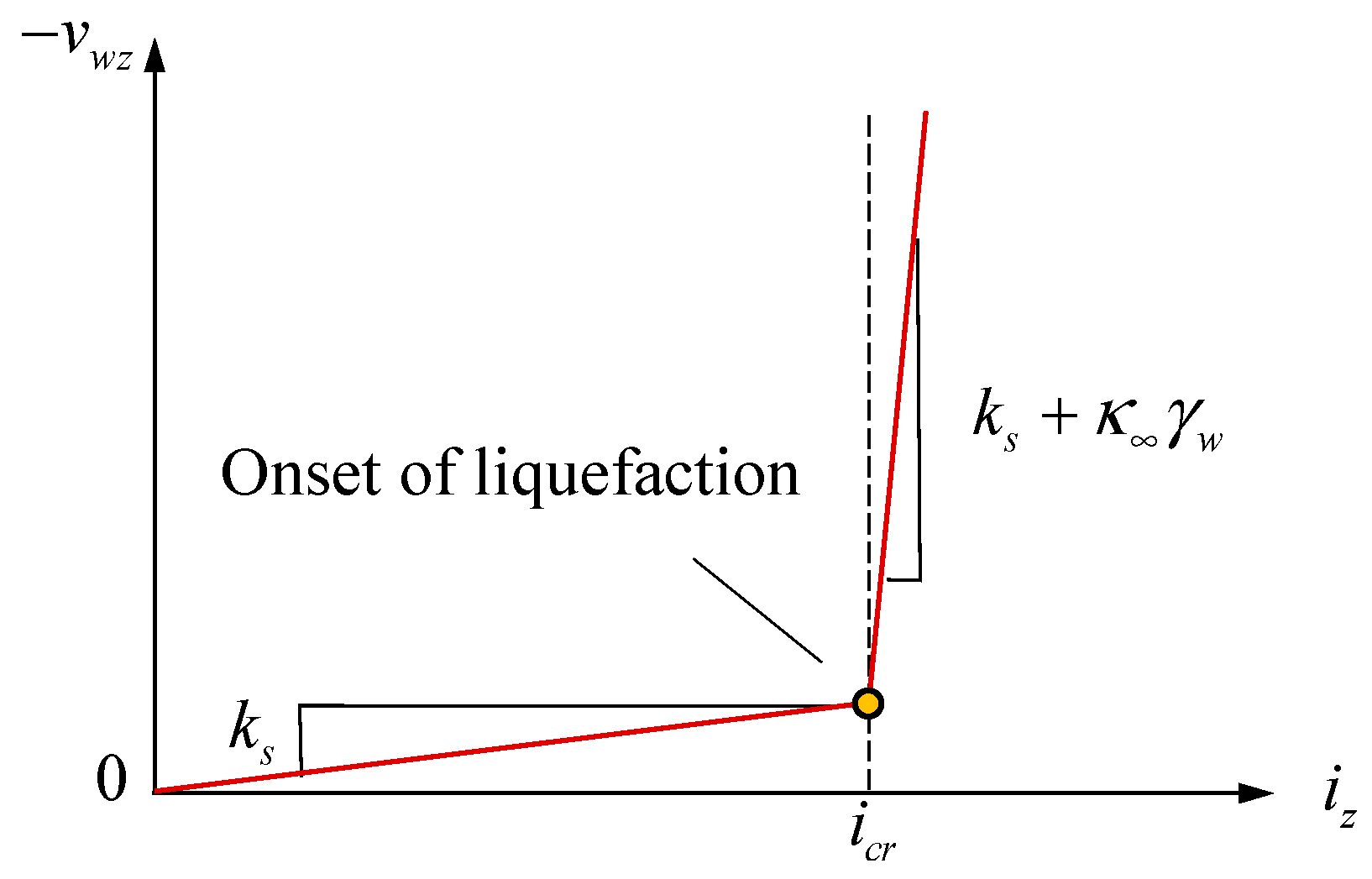
Because the pressure gradient is related to the hydraulic gradient i ( Δ p = γ w i ), v w z can be written as
v w z = k s i z κ i z i c r = k s i z , i f   i z < i c r   k s i c r k s + κ γ w i z i c r ,   i f   i z i c r ,
where i c r equals γ / γ w and represents the critical value that determines the occurrence of liquefaction. i z represents the vertical component of the hydraulic gradient. κ represents the penalty value and is generally taken as a large value, e.g., 1000.
The equations described above are shown in Figure 2 in the v w z i z space, which appears as the non-Darcy flow model.
After discretization, linearization, and other derivation steps (the specific derivation process has been provided by Zhou [63] and is omitted here), the finite element formulation using the non-Darcy flow model is obtained as follows:
K G G T H + L d u t , k d p t , k = F u F p ,
with
K = Ω B u T D B u d Ω ,
G = Ω B u T m N p d Ω ,
H = Ω n β N p T N p d Ω ,
L = τ γ w Ω B p T v w B p d Ω ,
F u = Ω N u T b d Ω Γ σ N u T t ^ d Γ ,
F p = G T d u t τ + H d p t τ + L d p t , k 1 + τ Γ v N p T v w n d Γ τ Ω B p T v w , h t , k 1 d Ω ,
with
B u = N u ,   m = { 1 , 1 , 0 , 0 } T ,   B p = N p
where d u and d p denote the discrete unknown vectors corresponding to the displacement (𝑢) and the excessive pore pressure (𝑝), respectively. The shape function matrices of d u and d p are N u and N p . v w denotes the partial derivative of v w with respect to i , and v w , h t denotes the current discrete velocity, while the subscripts k and k−1 are used to indicate the nonlinear iterations.
Based on the algebraic representations mentioned above, the iterative process for the solution ( d u t , d p t ) can be derived and conveniently applied in conventional finite element codes.

3. Validation of the Wave–Seabed–Structure Model without Seabed Liquefaction

3.1. Computational Model

The model without a structure and our finite element code have been validated by Zhou et al. [52,61,63], including cylinder tests under 1-D wave loading and two-dimensional (2-D) wave–seabed interactions. These validations are therefore not repeated here in this work.
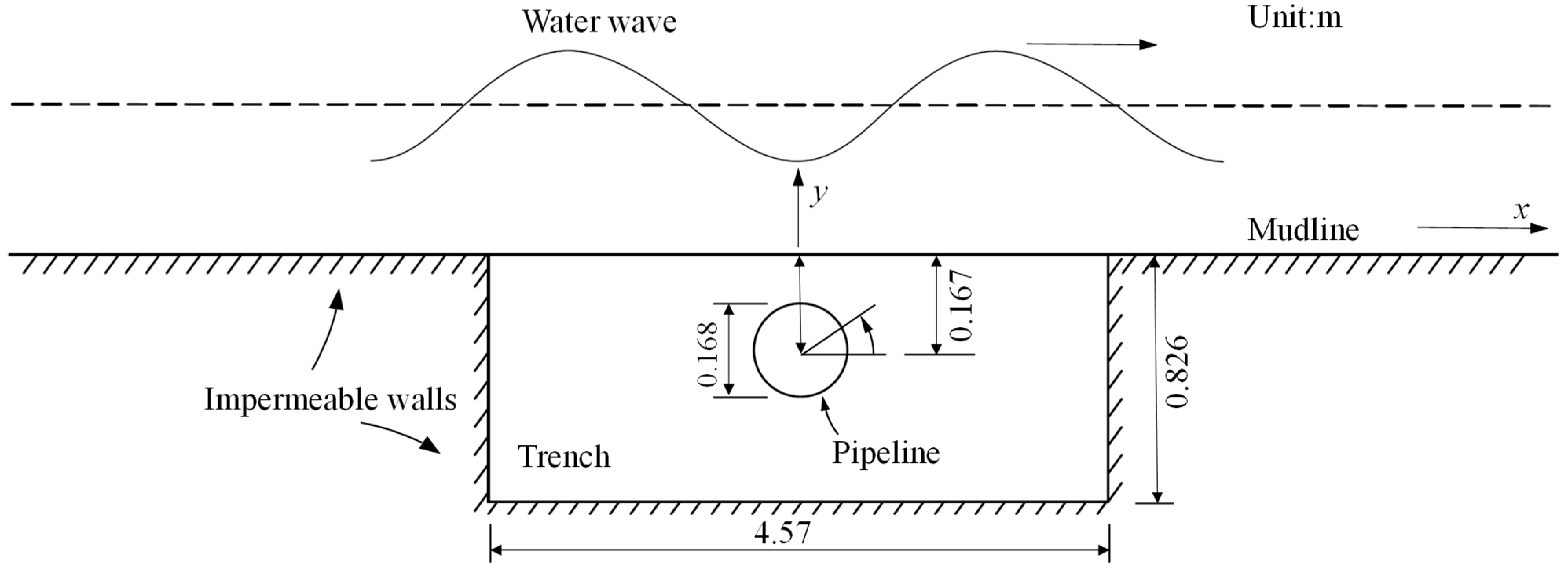
This section focuses on the validation of our finite element code applied to the scenario involving a structure, which is taken as a pipeline fully buried in the non-cohesive seabed. In this scenario, a series of flume tests were conducted by Turcotte [67], wherein seabed liquefaction was not induced. The model of these tests is shown in Figure 3. In the tests, the wave period T was 0.9–2.3 s and the wave height H was 3.02–14.3 cm, while L was 3.53 m, h was 0.533 m, S r was 0.997, n was 0.42, k s was 0.001 m·s−1, E was 3 MPa, and ν was 0.33. The computational model was then built according to the given conditions.

3.2. Pore Pressure Response

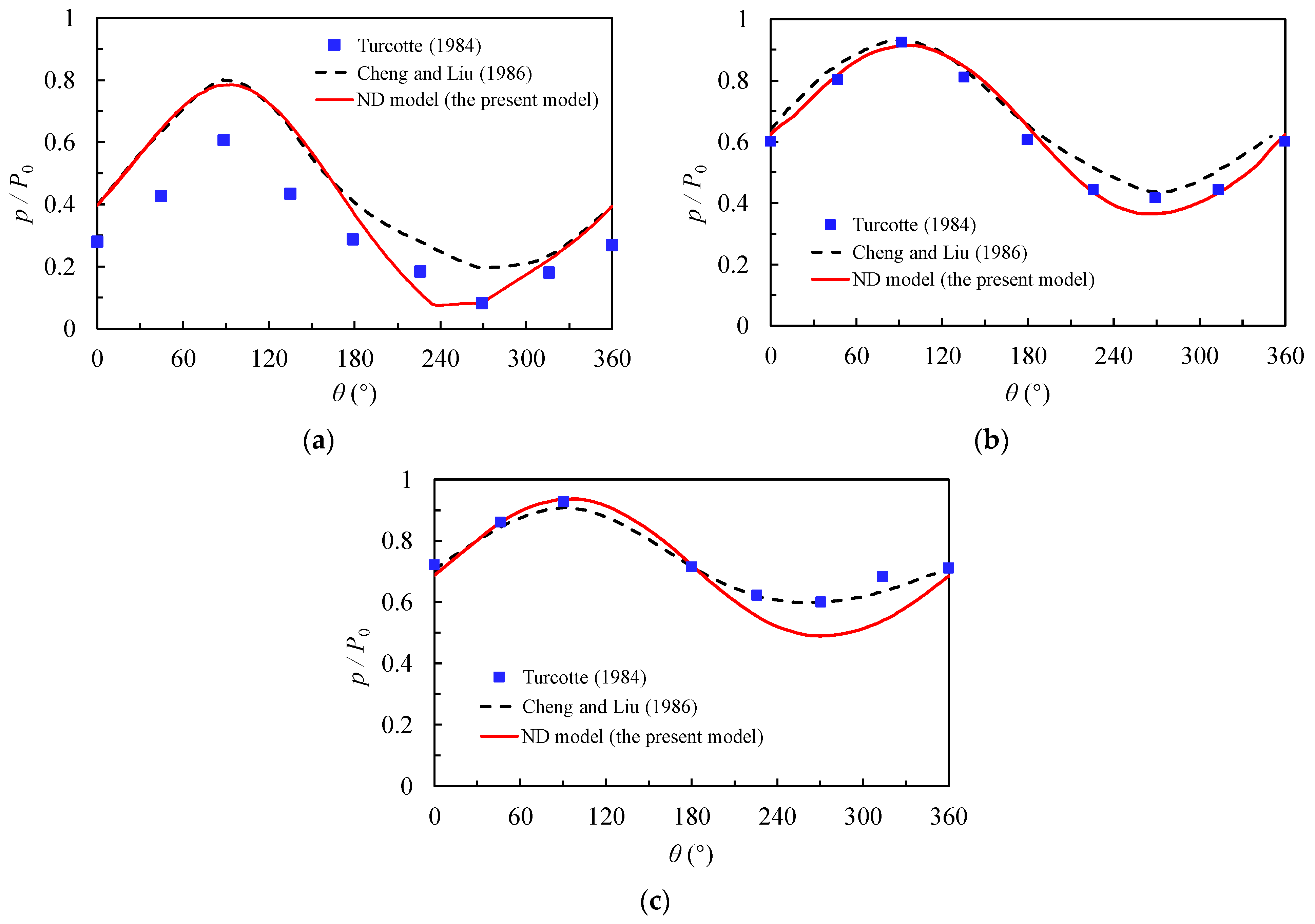
The distribution of pore pressure around the pipeline is shown in Figure 4. The vertical axis represents the normalized pore pressure p / P 0 . Cheng and Liu [72] also conducted numerical studies based on Turcotte’s flume experiments. For a better visual comparison, the numerical results of this study were compared with the flume experimental results of Turcotte [67] and the numerical results of Cheng and Liu [72]. It can be seen that our numerical results are in basic agreement with the experimental results of Turcotte [67] and the numerical results of Cheng and Liu [72].
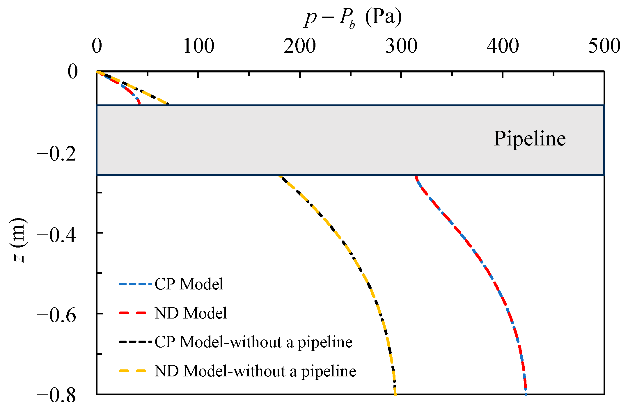
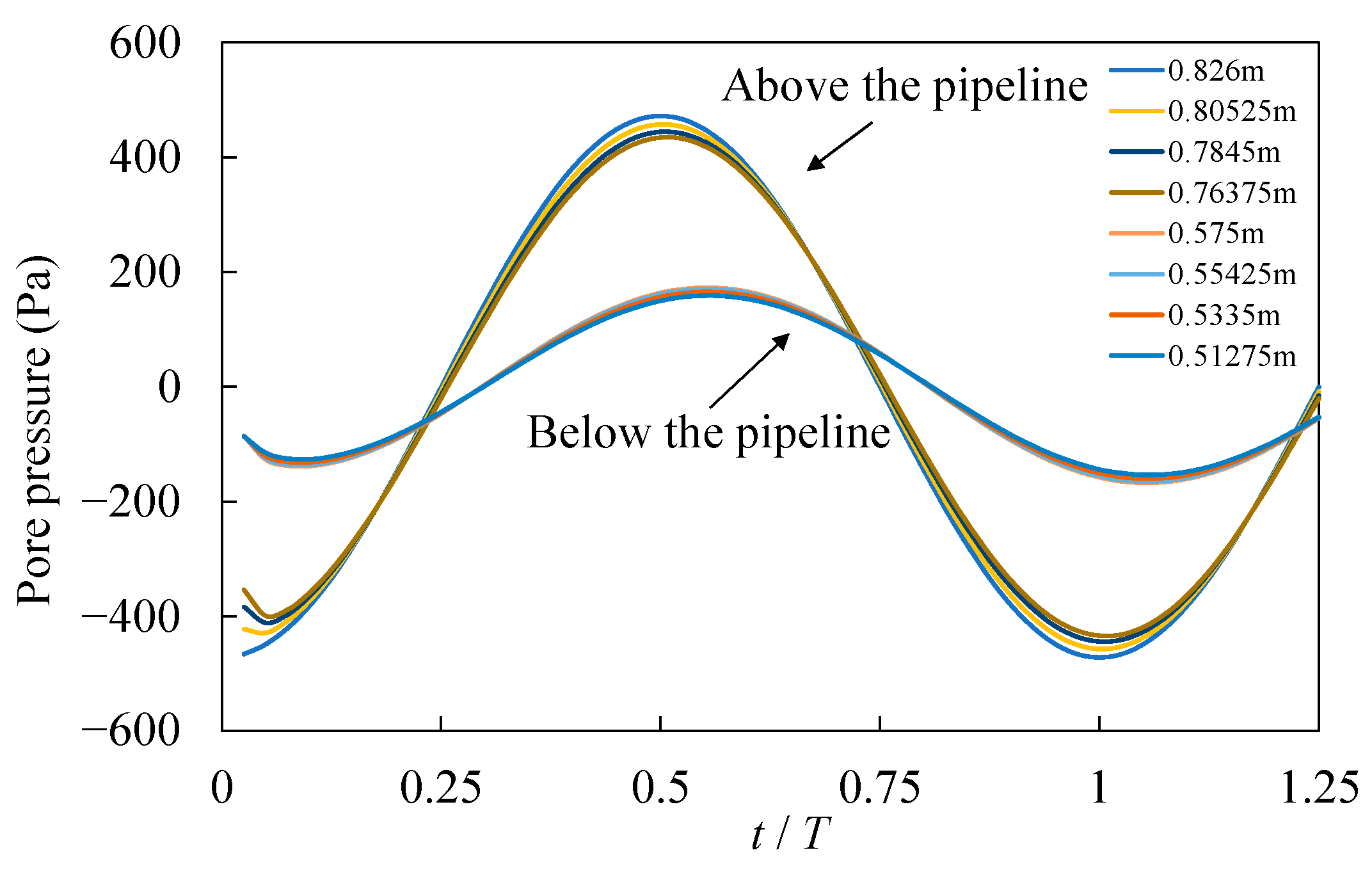
Figure 5 shows the distribution of p / P 0 along the depth direction of the centerline using the constant-permeability model (which is hereafter called the CP model) and the liquefaction-associated non-Darcy model (which is hereafter called the ND model) both with and without a pipeline. Due to the absence of liquefaction in the seabed, the results of the CP and ND models are completely consistent. A comparative analysis reveals that the presence of the pipeline significantly affects the transmission of pore pressure in the seabed. Above the pipeline, the pore pressure attenuation is slower in the seabed with a pipeline, but below the pipeline, the pore pressure decreases significantly. This can also be clearly observed in the pore pressure variations along the centerline of the seabed model (e.g., Figure 6, in which the variation in pore pressure versus time step at different depths is displayed). The specific reasons for this phenomenon will be discussed in Section 5.

4. Numerical Results of the Wave–Seabed–Structure Model with Seabed Liquefaction

4.1. Computational Model

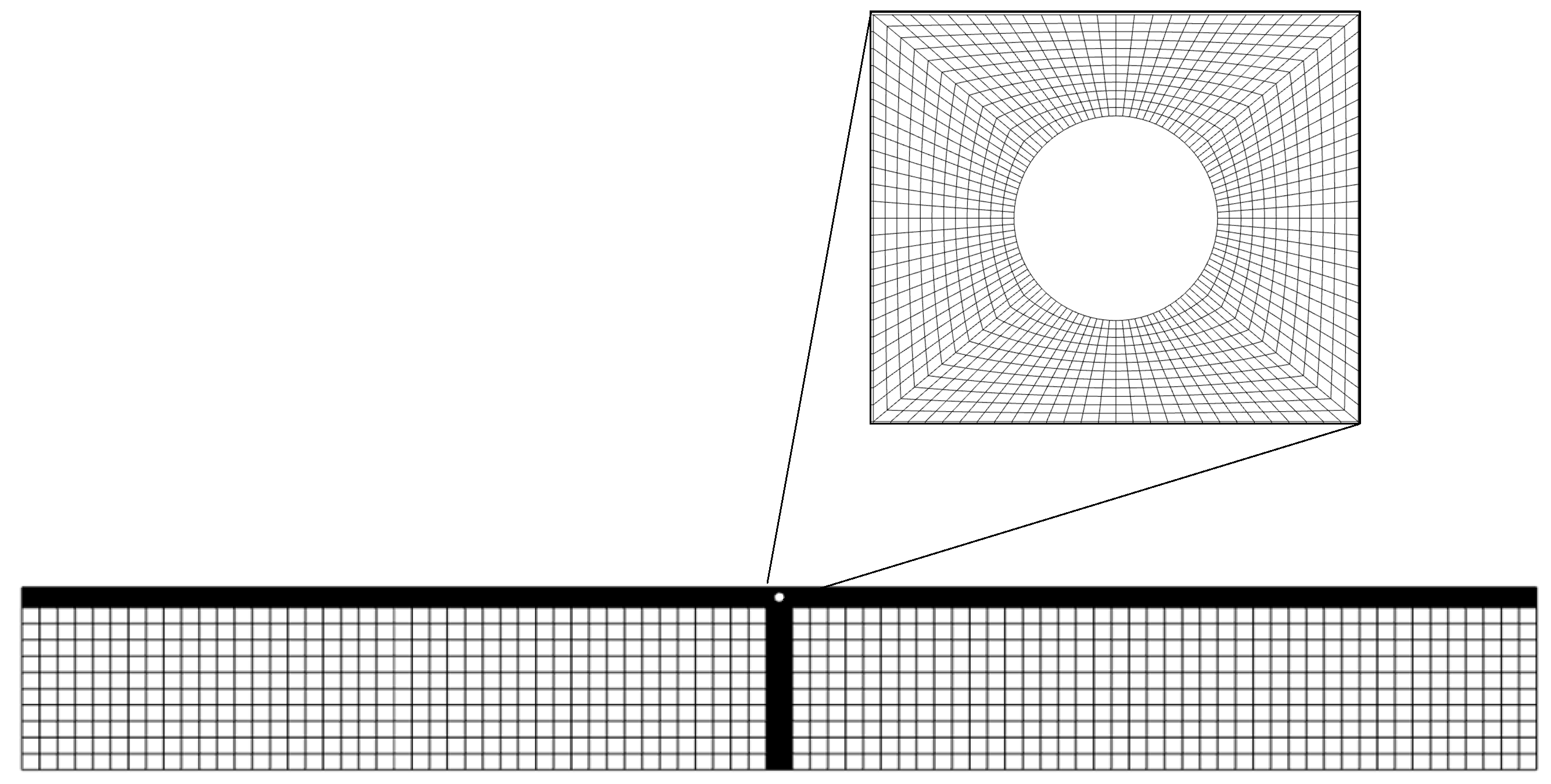
In this subsection, our liquefaction-associated non-Darcy flow model is utilized to analyze the wave–seabed–pipeline interaction under extreme wave loadings, which induce seabed liquefaction. The computational model adopts a two-dimensional approach. The width of the seabed in the computational model is assumed to be 50 m, with a thickness of 20 m. The computational mesh consisting of quadrilateral elements is shown in Figure 7. The seabed mesh surrounding the pipeline is refined in the meshing process, with a minimum mesh size of 0.01 m. The computational parameters are listed in Table 1. The burial depth and diameter are denoted by d and D, respectively, while d is defined as the distance from the top position of the pipeline to the seabed surface.

4.2. Pore Pressure Response

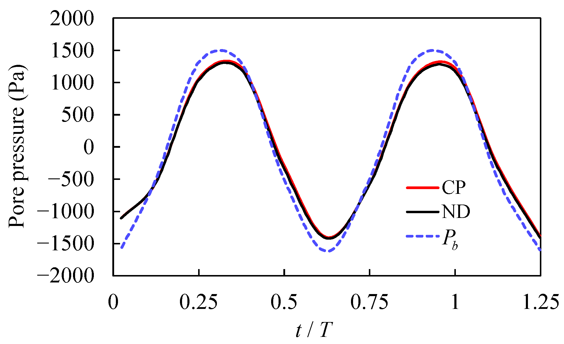
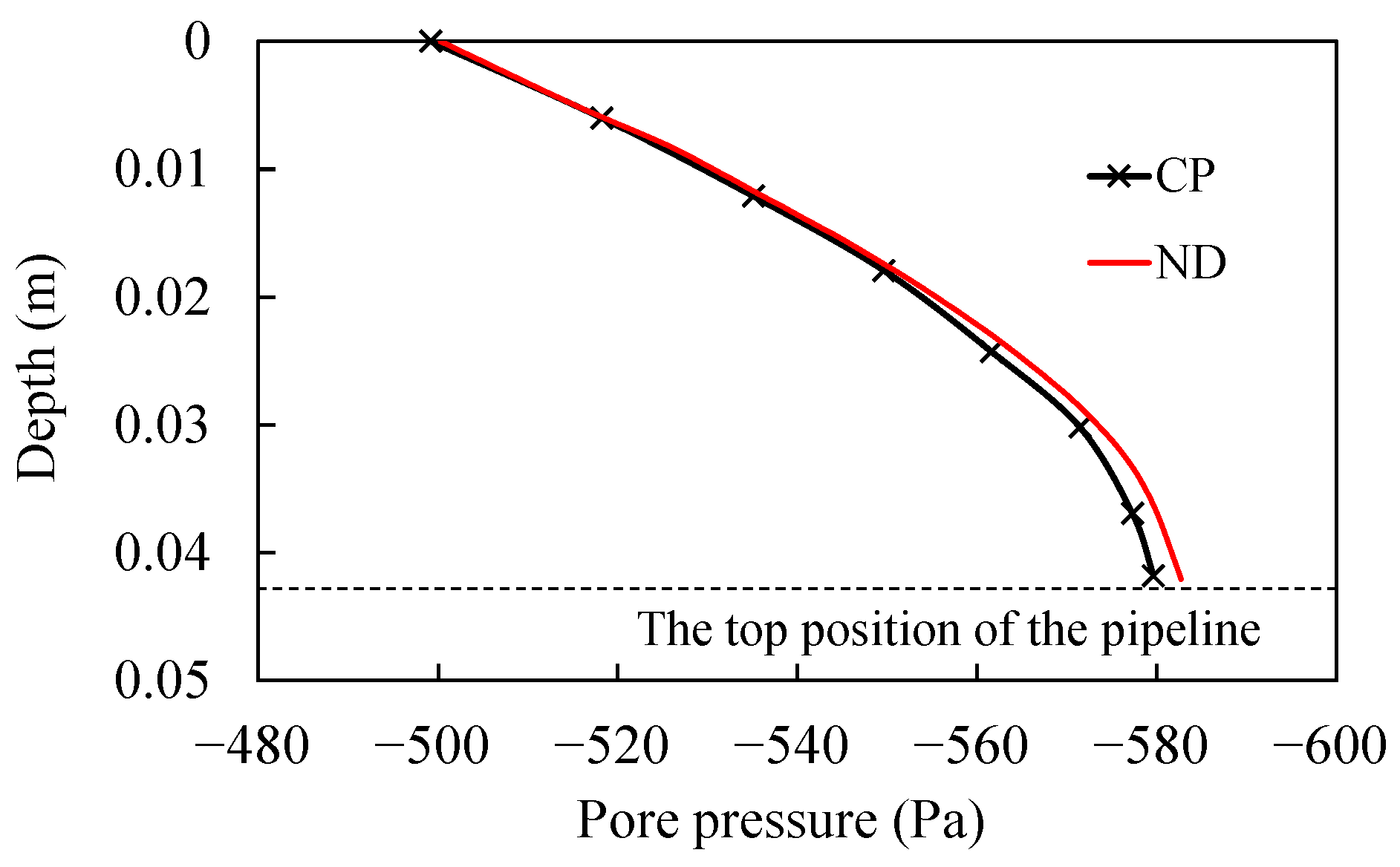
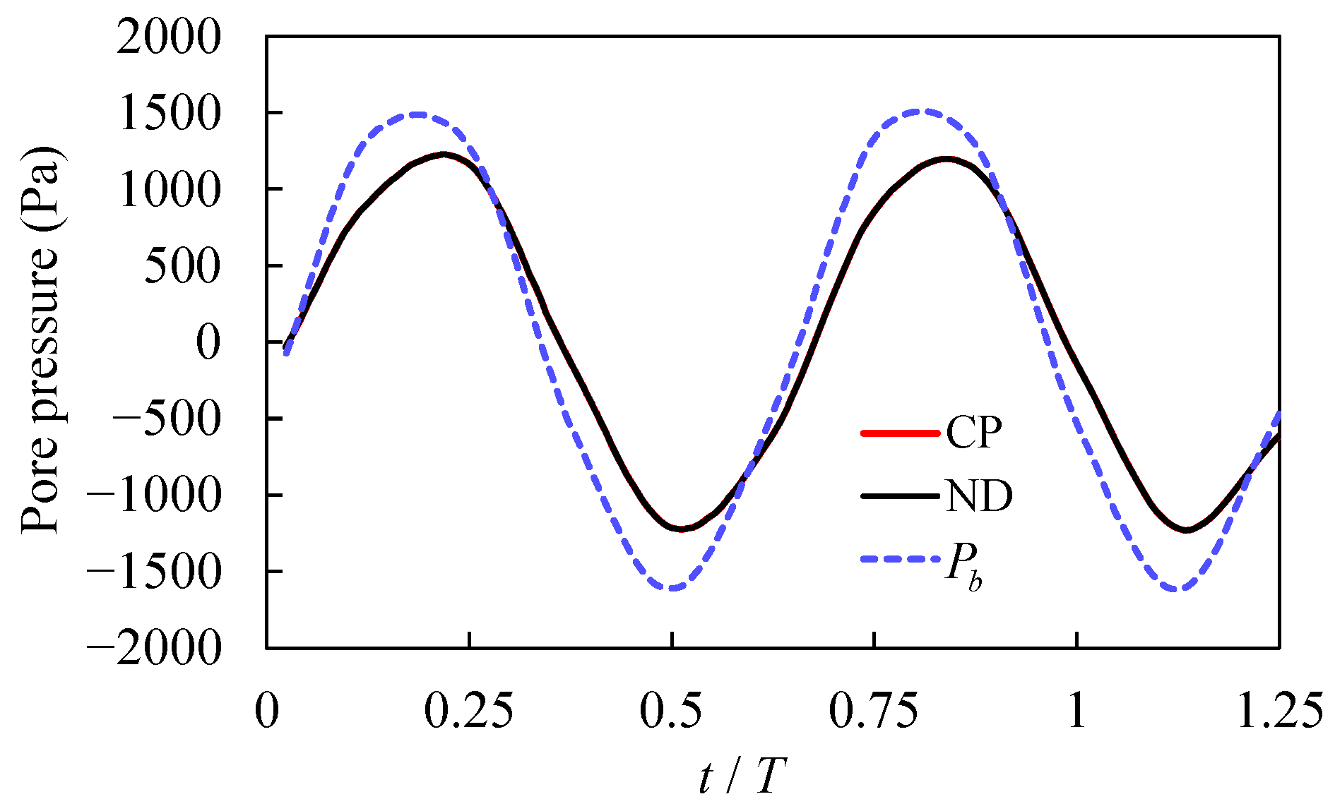
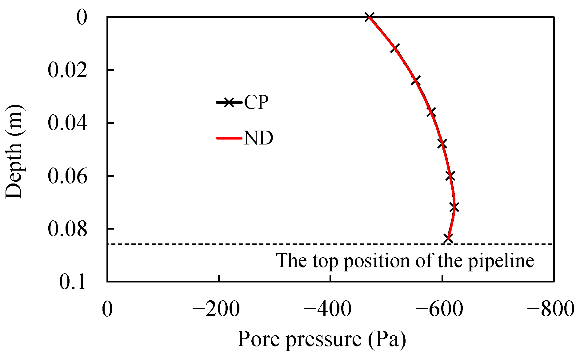
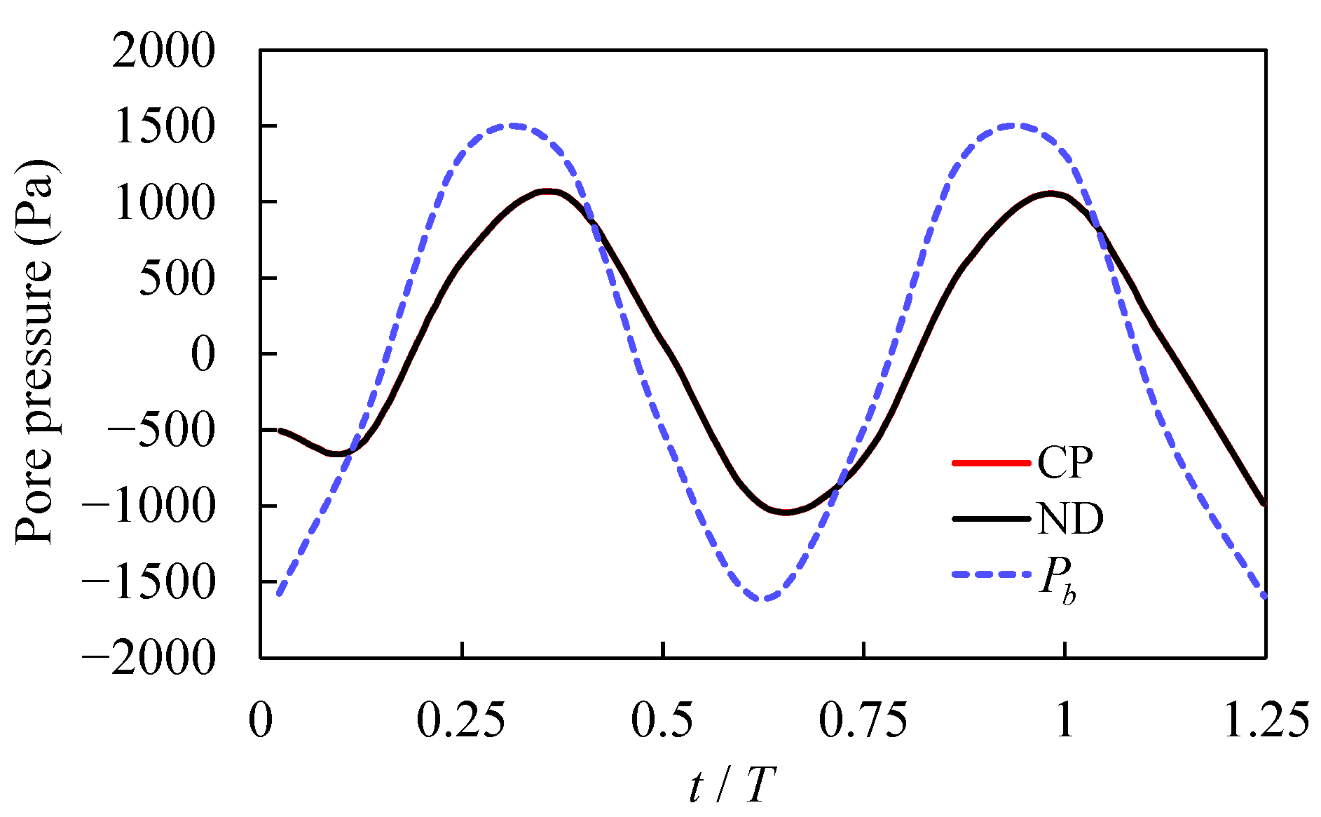
To investigate the influence of a fully buried pipeline on the pore pressure response in a non-cohesive seabed, three values of burial depth d are considered, as presented in Table 2, wherein the pipeline diameters are fixed at the same value of burial depth, i.e., d/D = 1. Figure 8, Figure 9, Figure 10, Figure 11, Figure 12 and Figure 13 give the temporal distributions of pore pressure at the top position of the pipeline and the vertical distributions of pore pressure above the top of the pipeline under three different schemes. In these figures, P b represents the wave pressure applied to the seabed surface.
The wave pressure is instantaneously transmitted from the sea surface to the seabed surface. However, due to the unsaturated nature of the seabed and the compressibility of pore water flow, the wave pressure cannot be promptly transmitted within the seabed, resulting in phase lag over time (e.g., Figure 8, Figure 10 and Figure 12) and amplitude attenuation along the depth direction (e.g., Figure 9, Figure 11 and Figure 13). The amplitude attenuation and phase lag are inherent characteristics of the wave-induced instantaneous pore pressure response.
According to Figure 8, Figure 10 and Figure 12, the results obtained from the CP model and ND models are close to each other. The variation in pore pressure at the top position of the pipeline follows the waveform of the wave motion. Under Scheme I, with a pipeline burial depth of 0.042 m, the wave pressure amplitude p 0 at the seabed surface is 1500 Pa, while the pore pressure amplitude at the top position of the pipeline is 1300 Pa, resulting in an amplitude attenuation of 13.3%. Compared to the amplitude of the wave pressure P b applied to the seabed surface, the pore pressure amplitude at the top position of the pipeline is delayed by about two computational steps, indicating a phase lag time of about 0.05T. Under Scheme II, with a pipeline burial depth of 0.084 m, p 0 at the seabed surface is 1500 Pa, while the pore pressure amplitude at the top position of the pipeline is 1200 Pa, resulting in an amplitude attenuation of 20.0%. Compared to the amplitude of P b applied to the seabed surface, the pore pressure amplitude at the top of the pipeline is delayed by about three computational steps, indicating a phase lag time of about 0.075T. Under Scheme III, with a pipeline burial depth of 0.126 m, P b at the seabed surface is 1500 Pa, while p 0 at the top position of the pipeline is 1100 Pa, resulting in an amplitude attenuation of 26.7%. The pore pressure amplitude at the top position of the pipeline appears at the same time as in Scheme II and is delayed by about three computational steps relative to the amplitude of P b applied to the seabed surface, indicating a phase lag time of about 0.075T. According to the above analysis, it can be concluded that as the burial depth of the pipeline increases, the degree of amplitude attenuation and the phase lag also increase.
According to Figure 9, Figure 11 and Figure 13, the pore pressure attenuation at a depth z = 0.04 m can be analyzed. The attenuation under Schemes I, II, and III is 13%, 25%, and 26.9%, respectively. With an increase in the structural burial depth, the degree of pore pressure attenuation also increases. In other words, a fully buried pipeline can mitigate the amplitude attenuation of pore pressure transmission within the seabed.
It can be seen that pipelines of different sizes and at different burial depths have different effects on the transfer of pore pressure in the seabed. The weakening of the seabed by the fully buried pipeline in the seabed is mainly due to the significant influence of its diameter and burial depth on the pore pressure transfer in the seabed, which is mainly manifested in the pore pressure amplitude attenuation and phase lag. The amplitude attenuation and phase lag are also the main reasons for the instantaneous liquefaction of the seabed.
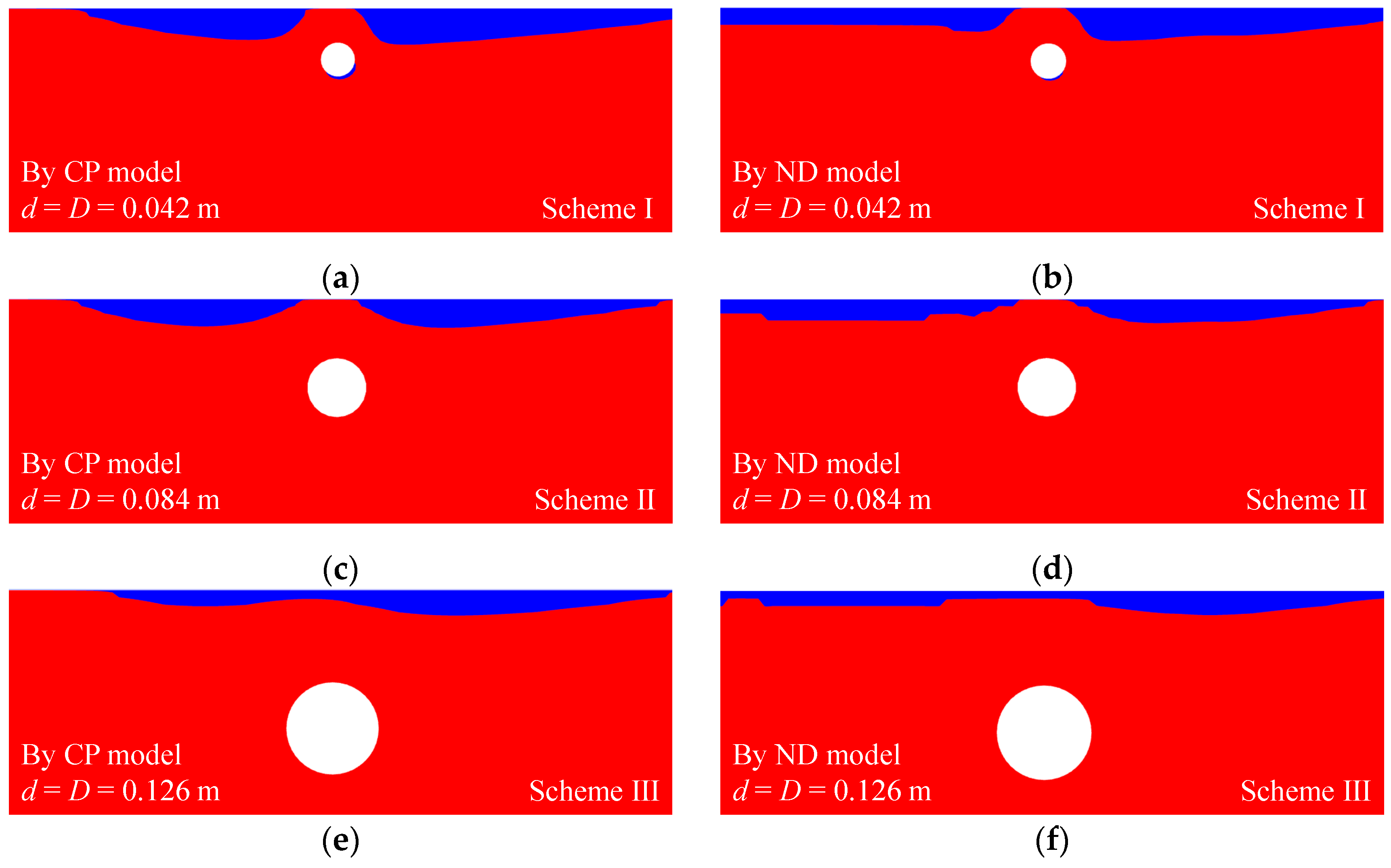
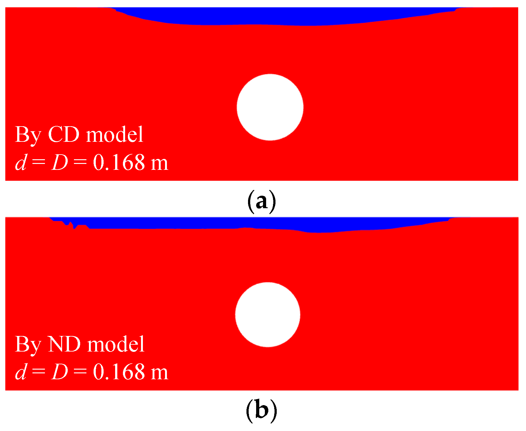
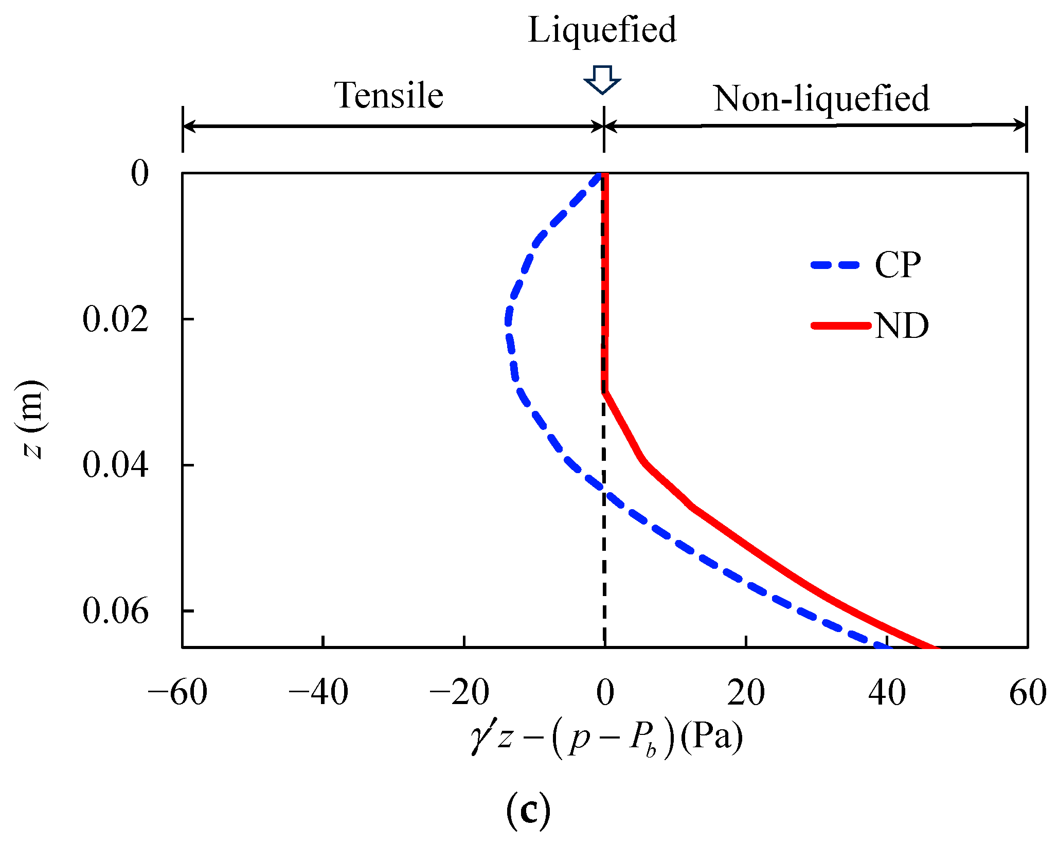
Figure 14 shows the liquefaction zones from the CP and ND models in the above three schemes. It can be seen that the liquefaction depth above the pipeline is nearly close to zero due to the liquefaction shielding effect, which is discussed in Section 5. As a result, the pore pressure distributions above the pipeline from the CP and ND models are close to each other, as shown in Figure 8, Figure 9, Figure 10, Figure 11, Figure 12 and Figure 13. To better illustrate the difference between the CP and ND models, another computational scheme (d = D = 0.168 m) is considered, with the numerical results shown in Figure 15. Figure 15a,b are the liquefaction zones from the CP and ND models, respectively. It can be seen that the liquefaction zone from the ND model is apparently smaller than that from the CP model. Figure 15c is the vertical effective stress above the pipeline centerline, showing that the ND model effectively mitigates the presence of tensile stresses caused by the CP model.

4.3. Parametric Study on the Liquefaction Depth

According to the research conducted by Zhou et al. [52,61,63], when there is no liquefied zone in the non-cohesive seabed, the results obtained by the ND model are consistent with those by the CP model. Once liquefaction occurs in the non-cohesive seabed, the CP model results in unreasonable tensile stresses within the liquefied zone, whereas the ND model does not produce such results. Therefore, Zhou et al. [52,61,63] suggest using the CP model for calculations in practical engineering scenarios first and employing the ND model to eliminate tensile stresses if liquefaction is observed. Through the parametric study by Zhou et al. [52,61,63], it was found that the instantaneous liquefaction depth from the ND model is approximately 0.73 times that from the CP model. This relationship is obtained in the scenario of a pure seabed without structures. Here, in this subsection, we further describe a parametric study conducted for the scenario involving a pipeline fully buried in the seabed.
During the parametric study, a benchmark test was set with the computational parameters listed in Table 1, and we considered seven different parameters (Young’s modulus 𝐸, permeability coefficient k s , saturation degree S r , soil porosity n, wave period T, water depth h, and wave height H). Building upon the model presented in Section 3.1, d and D of the pipeline are taken as 0.083 m and 0.168 m, respectively.
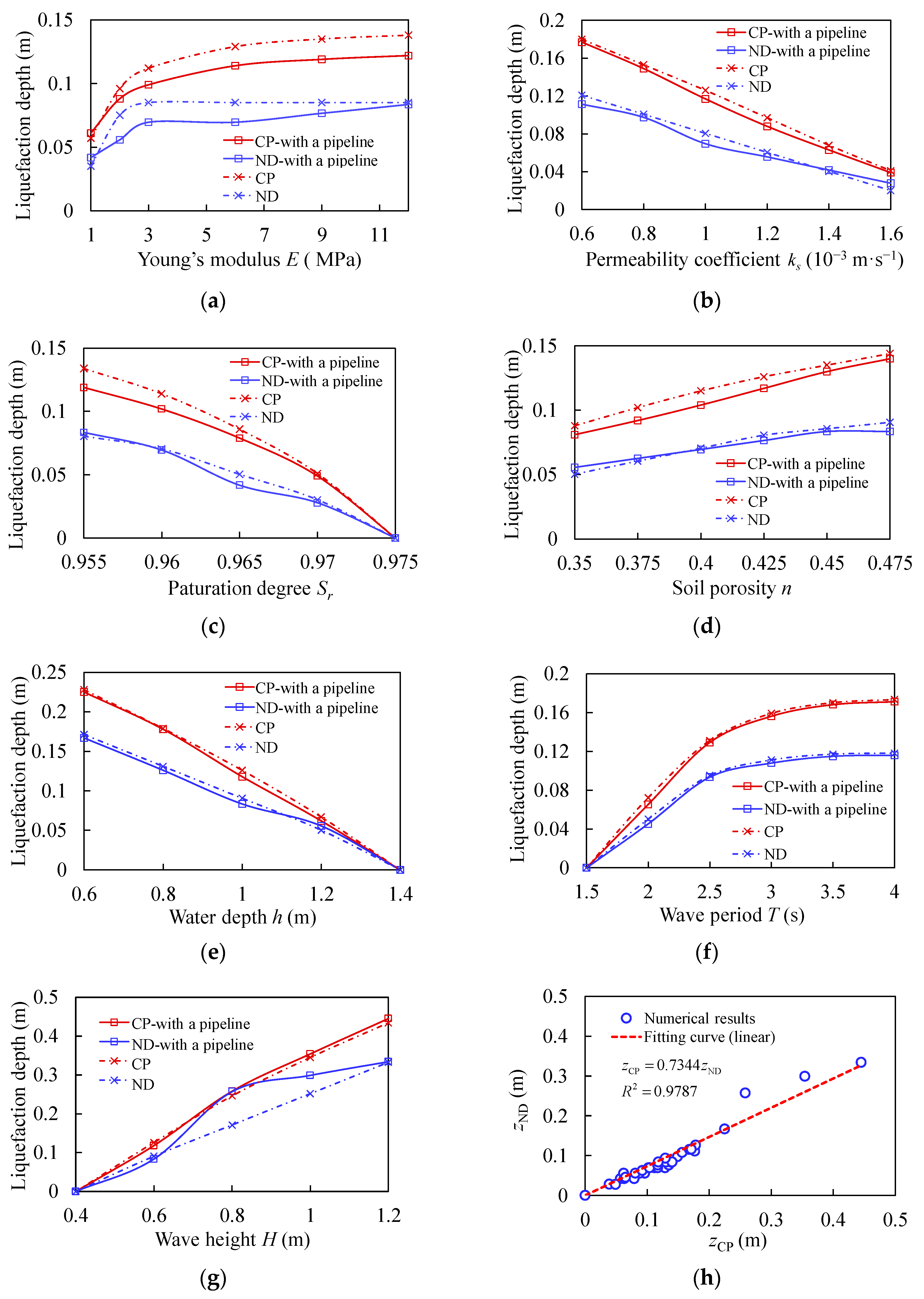
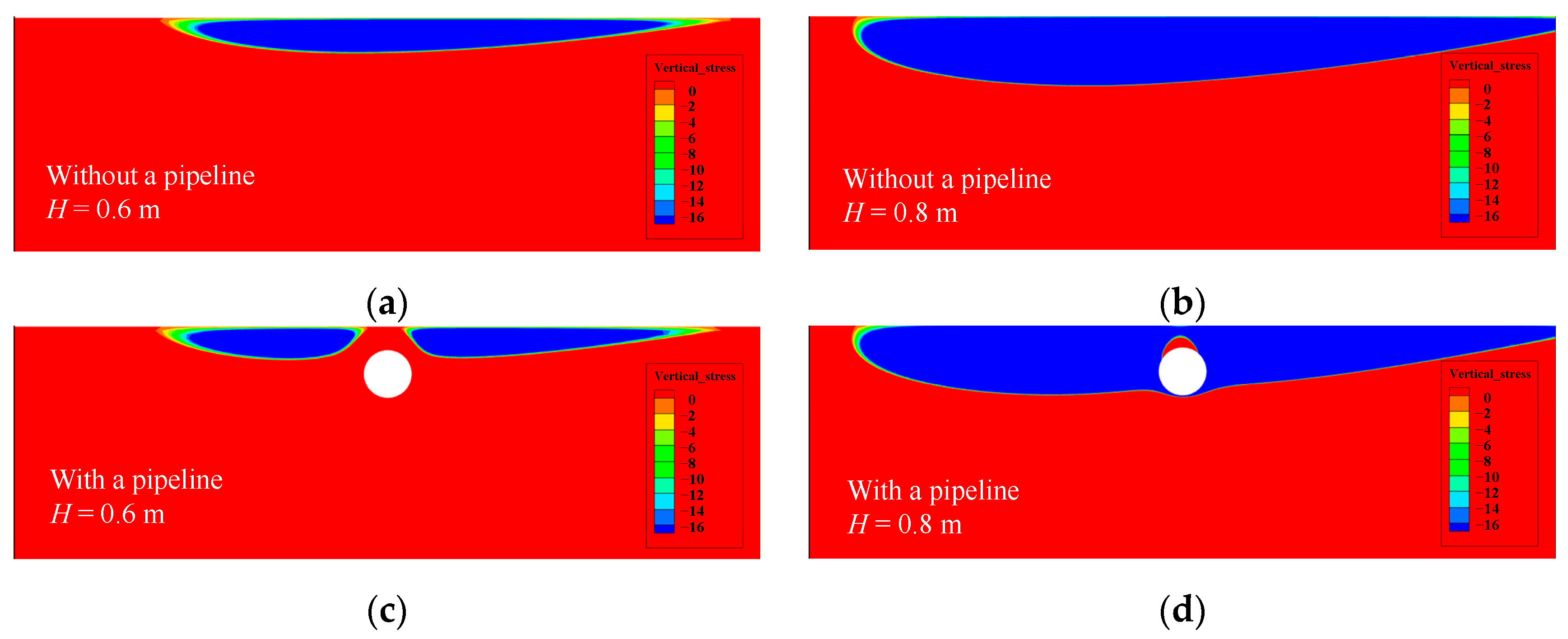
In Figure 16, CP represents the results of the CP model, while ND represents the results of the ND model, and the solid line represents the model with a pipeline, while the dashed line represents the model without a pipeline. Figure 16a shows that the liquefaction depth increases rapidly when the elastic modulus is between 1 and 3 MPa. As the elastic modulus exceeds 3 MPa, the rate of increase in liquefaction depth slows down and gradually approaches a constant value. In Figure 16b, it can be seen that the liquefaction depth decreases with the increase in the permeability coefficient. Figure 16c demonstrates the sensitivity of the liquefaction depth versus soil saturation. The presence of air in unsaturated soils is a key factor causing the amplitude attenuation and phase lag of pore pressure propagation in the seabed, thus directly affecting the liquefaction depth. Figure 16d shows that the liquefaction depth has a nearly linear relationship with the void ratio. In Figure 16e, it is evident that the liquefaction depth decreases linearly with the increase in water depth. Figure 16f reveals that the liquefaction depth increases and gradually approaches a constant value as the wave period increases. In Figure 16g, the change in liquefaction depth exhibits a roughly linear relationship with the wave height. The liquefaction depth increases with the increase in wave height and suddenly increases when the wave height reaches 0.8 m. This is because, during the process of increasing the wave height from 0.6 m to 0.8 m, a small liquefied zone also appears at the bottom of the pipeline, as shown in Figure 17. It can be therefore concluded that E, n, T, and H positively influence the liquefaction depth, while k s , S r , and h have a negative impact on it. Additionally, the liquefaction depth in the scenario with a pipeline is generally smaller than that in the scenario without a pipeline.
According to Figure 16h (where z CP represents the liquefaction depth from the CP model and z ND represents that from the ND model, which are all from Figure 16a–g), it can be observed that there is a significant linear correlation between z CP and z ND (with R 2 = 0.9787 ) in the scenario involving a pipeline. The ratio between the instantaneous liquefaction depth from the ND model and the CP model is approximately 0.73, which is close to that in the scenario of a pure seabed without structures.

4.4. Study on Non-Dimensional Parameters

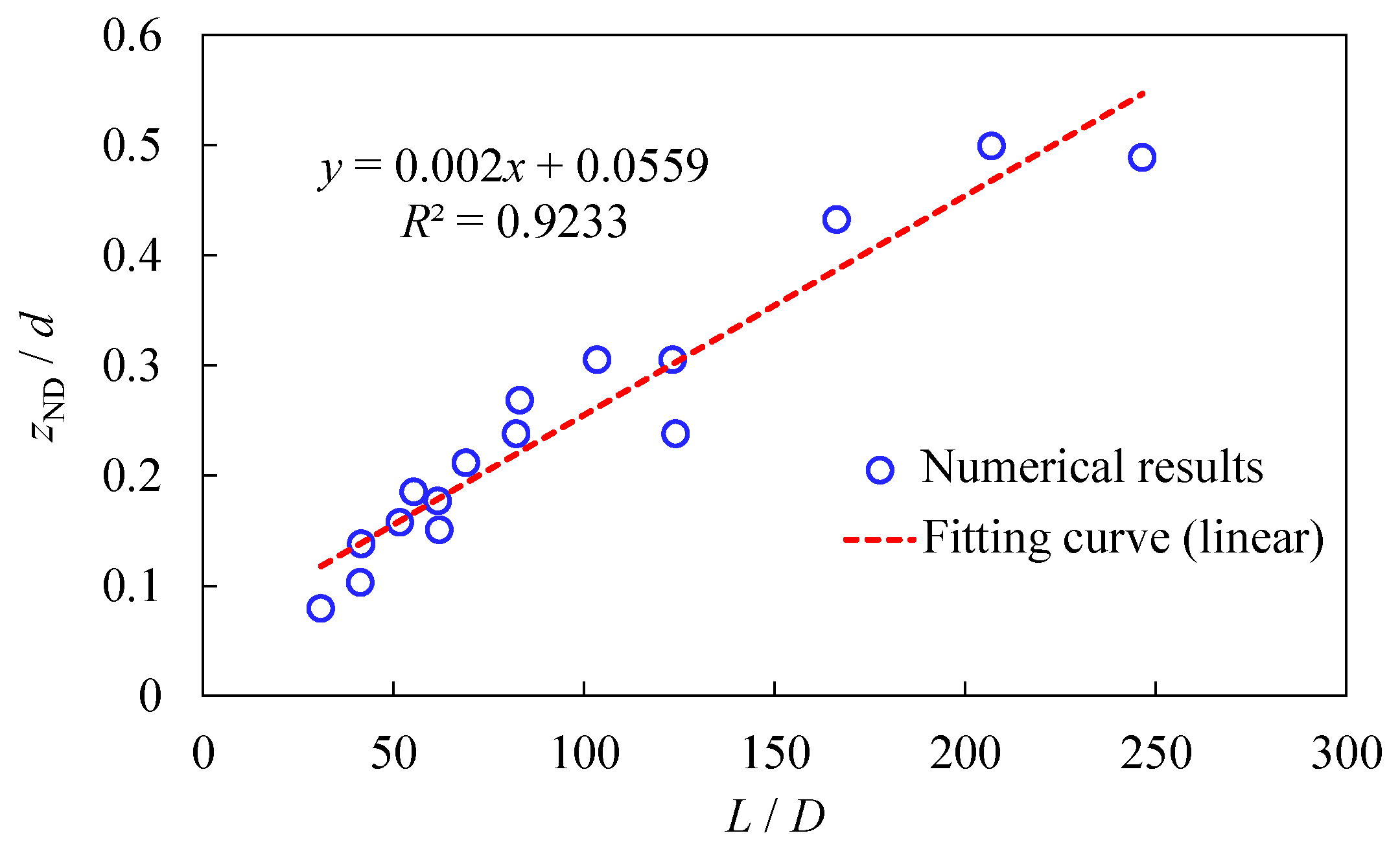
To establish a quantifiable relationship between wave loads and structural responses with good universality, it is necessary to develop an expression based on non-dimensional parameters. To achieve this, adopting schemes with diameters ranging from 0.042 to 0.168 m and burial depths of 1–5 times the diameters (the specific values of burial depths and diameters are given in Table 3, while S r is 0.96, ν is 0.3, and the other parameters are the same as those in Table 1), we conducted a large number of numerical calculations and attempted various combinations of horizontal and vertical parameters. Eventually, we found that when the horizontal coordinate is L / D (wavelength/diameter) and the vertical coordinate is z ND / d (liquefaction depth/burial depth), there is a significant linear relationship between them, as shown in Figure 18. The correlation coefficient ( R 2 ) was as high as 0.9223, indicating a good fitting effect.

5. The Shielding Phenomenon of a Structure in the Seabed under a Liquefaction Condition

5.1. The Shielding Effect of the Pipeline on the Liquefied Zone

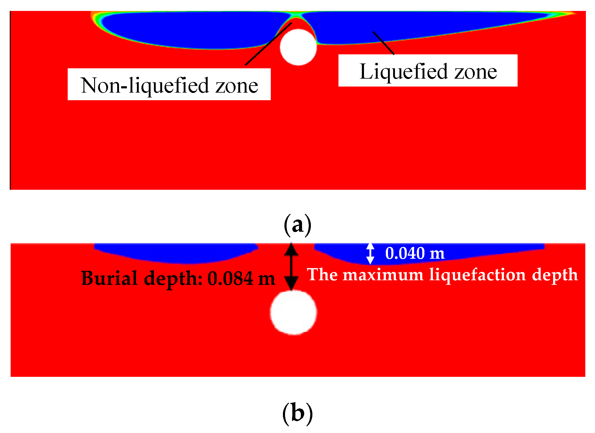
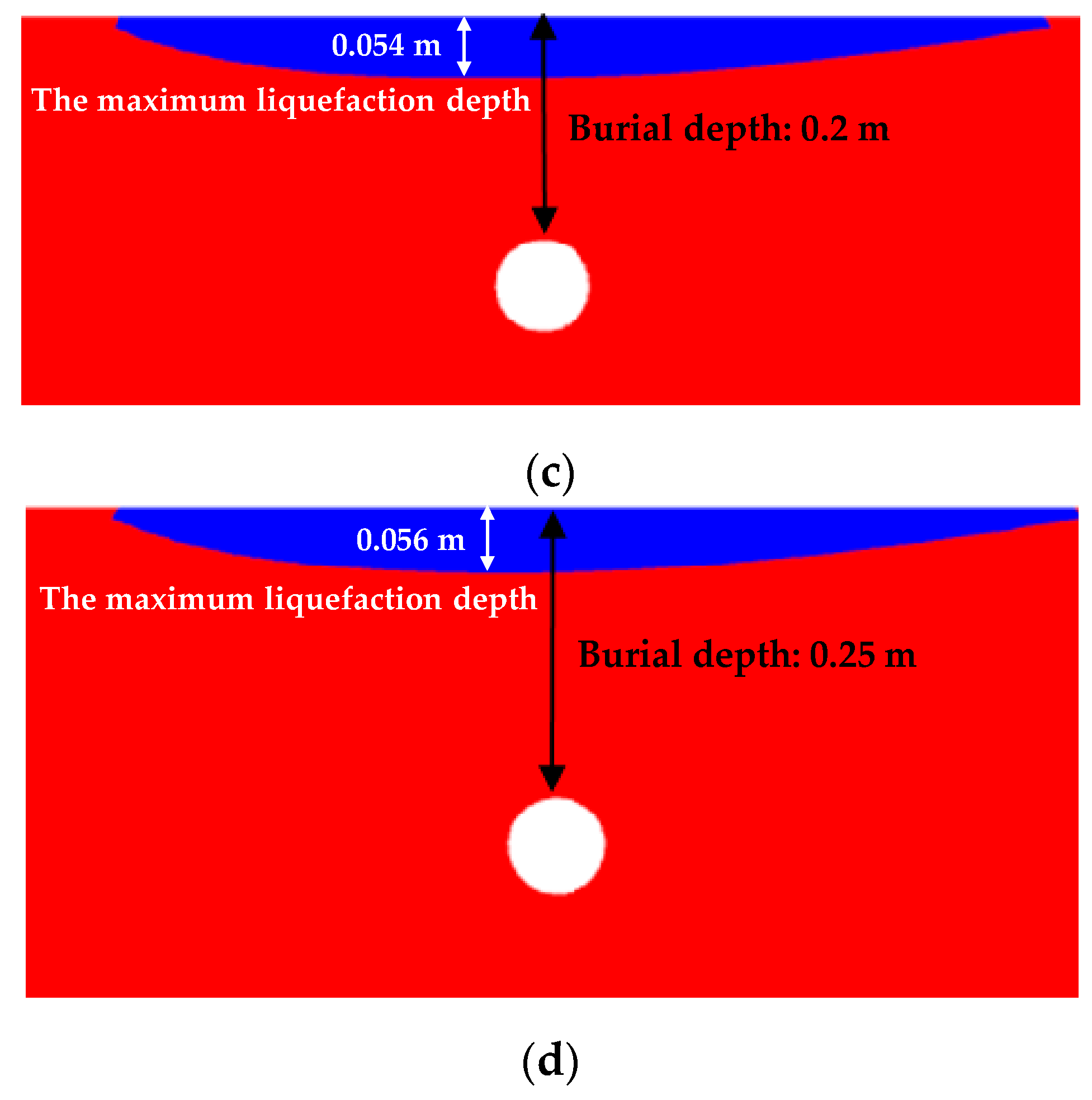
In Section 4.3, it is shown that the presence of a pipeline in the seabed leads to a smaller liquefaction depth compared to the scenario without a pipeline. When a pipeline exists in the seabed, the liquefied zones above the pipeline exhibit a spatial distribution that “bypasses” the pipeline, resulting in a “liquefaction shielding phenomenon”. Even if the liquefaction depth on both sides of the pipeline is below the top position of the pipeline, there will be a layer of non-liquefied soil above the pipeline, e.g., Figure 19a. As shown in Figure 19b–d, as the burial depth of the pipeline increases, keeping the diameter constant, the liquefaction depth also increases. However, when the burial depth is large enough, its further increase will not induce a further increase in the liquefaction depth. The reason is that instantaneous liquefaction generally occurs in a thin layer near the seabed surface. When the pipeline is far away from the seabed surface, the presence of the pipeline will no longer influence the liquefied zone. In contrast, when the buried depth is not large enough, the presence of the pipeline can have a significant influence on the liquefied zone. Below, a tentative explanation is provided for this phenomenon.
During the numerical simulation, the presence of the pipeline acts as an impermeable boundary in the seabed, causing a diversion of the flow field in the surrounding area, as shown in Figure 20. The flow does not reach the soil above the pipeline immediately, resulting in an impact on the phase lag and amplitude attenuation of the wave-induced seabed pore pressure response, and this phenomenon is referred to as the “liquefaction shielding phenomenon”. In other words, when the structure is shallow, the structure will repel the liquefaction zone above it, and the area above the structure where liquefaction does not occur is referred to as the “shielding ring”. It is therefore straightforward to imagine that when the pipeline is shallow enough, the liquefied zone above the pipeline can completely disappear. This prediction is studied in the following subsection.

5.2. Onset Conditions for Liquefaction Occurrence above the Pipeline

According to Section 5.1, the shielding phenomenon of the pipeline on the liquefied zone weakens as the burial depth of the pipeline increases. This subsection will present a computational analysis of various combinations of burial depth d and diameter D to study the onset conditions for liquefaction occurrence above the pipeline.
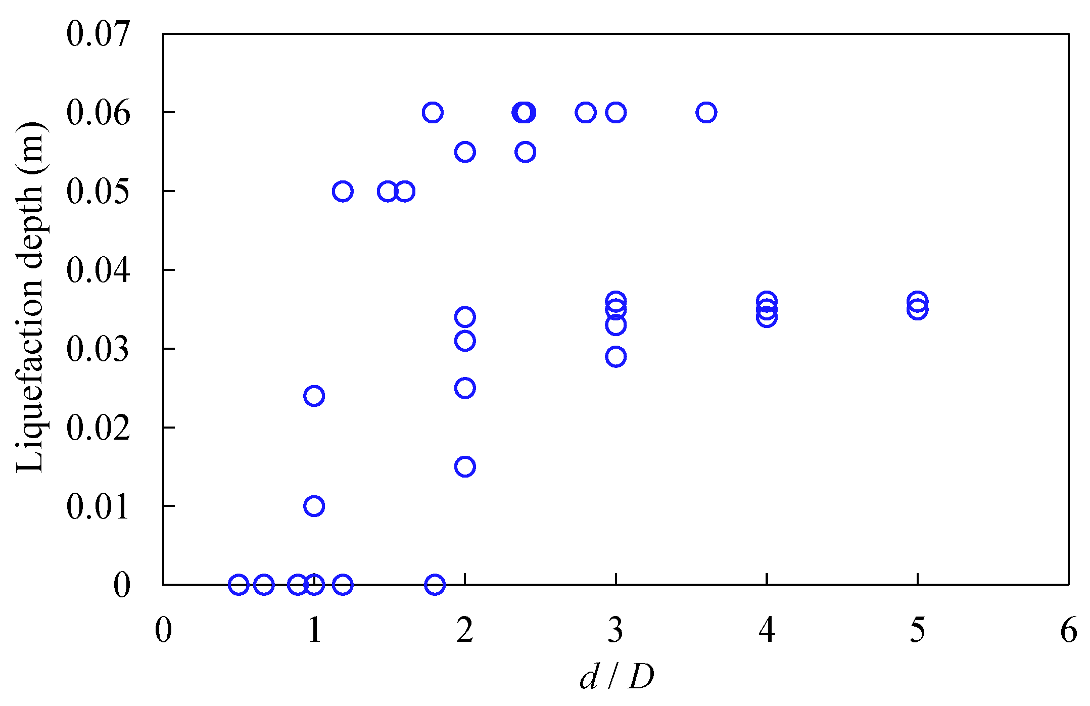
Based on the numerical results in Section 4.4, we continued to calculate the liquefaction depths in the scenario involving a pipeline considering various schemes with diameters of 0.084 m, 0.126 m, and 0.168 m and burial depths ranging from 0.084 m to 0.4 m (please refer to Table 4 for specific parameters and results). The results in Section 4.4 and Table 4 are jointly plotted in Figure 21. When d / D < 2 , although several schemes have liquefaction depths as high as 0.06 m, nearly half of the schemes did not show liquefied zones; i.e., the pipeline is near the seabed surface, and therefore, the aforementioned shielding effect is apparent. However, when d / D 2 , liquefaction zones occur in all the numerical results, with a minimum liquefaction depth of 0.015 m; i.e., the pipeline is far away from the seabed surface and therefore has a slight influence on the liquefied zone.
It seems that a critical value of d / D can be quantitatively determined to distinguish whether liquefaction occurs above the pipeline. From Figure 21, this value can be taken as 2; i.e., when d / D 2 , liquefaction always occurs above the pipeline. It should be noted that this critical value can change if other computational parameters are applied. It is also notable that even if there is no liquefied zone above the pipeline, in the horizontal direction, if a position is far from the pipeline, the shielding effect of the pipeline can also disappear, which means that liquefied zones can also occur in a shallow layer of the seabed within these areas, e.g., Figure 19b.

6. Conclusions

This paper extends the application of our liquefaction-associated non-Darcy flow model from wave–seabed interactions to wave–seabed–pipeline interactions in order to investigate the influence of a fully buried pipeline on the pore pressure response and the instantaneous liquefaction of the non-cohesive seabed. Based on the numerical examples presented, the following conclusions can be drawn.
(1)
Numerical simulations were conducted based on Turcotte’s flume experiment, validating the reliability of our in-house code in modeling wave–seabed–structure interactions.
(2)
A numerical study was conducted by varying the burial depth and diameter of the pipeline, revealing that the existence of a pipeline weakens the degree of amplitude attenuation and the phase lag. Therefore, when the pipeline is shallow, the liquefied zone of the seabed with a pipeline is smaller than that in the pure seabed, which is called the “liquefaction shielding effect” in this work.
(3)
Under some conditions, liquefaction can even completely disappear above the pipeline, while horizontally distant areas still have liquefied zones. The onset conditions for liquefaction occurrence above the pipeline are then discussed.
(4)
As the burial depth of the pipeline increases, the liquefaction shielding effect weakens, resulting in an increase in the liquefaction depth above the pipeline. Once the pipeline is sufficiently far from the seabed surface, it no longer influences the liquefied zone.
(5)
Based on the parametric study, it was observed that the liquefaction depth predicted by the non-Darcy model is approximately 0.73 times the value estimated by the conventional Darcy model, regardless of whether or not a pipeline is involved.
(6)
The quantitative relationship between wave loadings and structural sizes is studied. A highly linear relationship between two sets of non-dimensional parameters, i.e., “liquefaction depth/burial depth” and “wavelength/diameter”, is discovered.

Author Contributions

Conceptualization, M.Z., D.Z., W.Q. and Q.F.; methodology, S.H. and M.Z.; software, M.Z.; validation, S.H. and C.X.; writing—original draft preparation, S.H.; writing—review and editing, M.Z., D.Z., W.Q. and Q.F.; visualization, S.H. and C.X.; supervision, D.Z., W.Q. and Q.F. All authors have read and agreed to the published version of the manuscript.

Funding

This study was financially supported by the Fundamental Research Funds for the Central Universities (Grant No. 2023JBZY027); the National Natural Science Foundation of China (Grant Nos. 52271255, 11972036); and the Youth Innovation Promotion Association CAS (Grant No. 2021018) for financial support.

Data Availability Statement

Data is contained within the article.

Conflicts of Interest

The authors declare no conflict of interest.

References

  1. Du, X.; Sun, Y.; Song, Y.; Zhu, C. In-Situ Observation of Wave-Induced Pore Water Pressure in Seabed Silt in the Yellow River Estuary of China. J. Mar. Environ. Eng. 2021, 10, 305–317. [Google Scholar]
  2. Jia, Y.; Zhang, L.; Zheng, J.; Liu, X.; Jeng, D.-S.; Shan, H. Effects of wave-induced seabed liquefaction on sediment re-suspension in the Yellow River Delta. Ocean Eng. 2014, 89, 146–156. [Google Scholar] [CrossRef]
  3. Mory, M.; Michallet, H.; Bonjean, D.; Piedra-Cueva, I.; Barnoud, J.M.; Foray, P.; Abadie, S.; Breul, P. A Field Study of Momentary Liquefaction Caused by Waves around a Coastal Structure. J. Waterw. Port Coast. Ocean Eng. 2007, 133, 28–38. [Google Scholar] [CrossRef]
  4. Tian, Z.; Chen, T.; Yu, L.; Guo, X.; Jia, Y. Penetration depth of the dynamic response of seabed induced by internal solitary waves. Appl. Ocean Res. 2019, 90, 101867. [Google Scholar] [CrossRef]
  5. Zhang, S.; Jia, Y.; Zhang, Y.; Liu, X.; Shan, H. In situ observations of wave pumping of sediments in the Yellow River Delta with a newly developed benthic chamber. Mar. Geophys. Res. 2018, 39, 463–474. [Google Scholar] [CrossRef]
  6. Jeng, D.-S. Mechanics of Wave-Seabed-Structure Interactions: Modelling, Processes and Applications; Cambridge University Press: Cambridge, UK, 2018. [Google Scholar]
  7. Sumer, T.B.M. Liquefaction around Marine Structures; World Scientific: Singapore, 2014. [Google Scholar]
  8. Jeng, D.-S. Wave-induced sea floor dynamics. Appl. Mech. Rev. 2003, 56, 407–429. [Google Scholar] [CrossRef]
  9. Zen, K.; Yamazaki, H. Mechanism of Wave-Induced Liquefaction and Densification in Seabed. Soils Found. 1990, 30, 90–104. [Google Scholar] [CrossRef] [PubMed]
  10. Miyamoto, J.; Sassa, S.; Sekiguchi, H. Progressive solidification of a liquefied sand layer during continued wave loading. Géotechnique 2004, 54, 617–629. [Google Scholar] [CrossRef]
  11. Mutlu Sumer, B.; Hatipoglu, F.; Fredsøe, J.; Kaan Sumer, S. The sequence of sediment behaviour during wave-induced liquefaction. Sedimentology 2006, 53, 611–629. [Google Scholar] [CrossRef]
  12. Hsu, J.R.C.; Jeng, D.S. Wave-induced soil response in an unsaturated anisotropic seabed of finite thickness. Int. J. Numer. Anal. Methods Geomech. 1994, 18, 785–807. [Google Scholar] [CrossRef]
  13. Madsen, O.S. Wave-Induced Pore Pressures and Effective Stresses in A Porous Bed. Geotechnique 1978, 28, 377–393. [Google Scholar] [CrossRef]
  14. Yamamoto, T.; Koning, H.L.; Sellmeijer, H.; Vanhijum, E.P. Response of A Poro-Elastic Bed to Water-Waves. J. Fluid Mech. 1978, 87, 193–206. [Google Scholar] [CrossRef]
  15. Zhang, Y.; Jeng, D.S.; Gao, F.P.; Zhang, J.S. An analytical solution for response of a porous seabed to combined wave and current loading. Ocean Eng. 2013, 57, 240–247. [Google Scholar] [CrossRef]
  16. Duan, L.; Liao, C.; Jeng, D.; Chen, L. 2D numerical study of wave and current-induced oscillatory non-cohesive soil liquefaction around a partially buried pipeline in a trench. Ocean Eng. 2017, 135, 39–51. [Google Scholar] [CrossRef]
  17. Gao, F.P.; Jeng, D.S.; Sekiguchi, H. Numerical study on the interaction between non-linear wave, buried pipeline and non-homogenous porous seabed. Comput. Geotech. 2003, 30, 535–547. [Google Scholar] [CrossRef]
  18. Jeng, D.S.; Lin, Y.S. Wave–induced pore pressure around a buried pipeline in Gibson soil: Finite element analysis. Int. J. Numer. Anal. Methods Geomech. 1999, 23, 1559–1578. [Google Scholar] [CrossRef]
  19. Li, K.; Guo, Z.; Wang, L.; Jiang, H. Effect of seepage flow on shields number around a fixed and sagging pipeline. Ocean Eng. 2019, 172, 487–500. [Google Scholar] [CrossRef]
  20. Liang, Z.; Jeng, D.-S. PORO-FSSI-FOAM model for seafloor liquefaction around a pipeline under combined random wave and current loading. Appl. Ocean Res. 2021, 107, 102497. [Google Scholar] [CrossRef]
  21. Liang, Z.; Jeng, D.-S.; Liu, J. Combined wave–current induced seabed liquefaction around buried pipelines: Design of a trench layer. Ocean Eng. 2020, 212, 107764. [Google Scholar] [CrossRef]
  22. Lin, Z.; Guo, Y.; Jeng, D.S.; Liao, C.; Rey, N. An integrated numerical model for wave–soil–pipeline interactions. Coast. Eng. 2016, 108, 25–35. [Google Scholar] [CrossRef]
  23. Zhao, H.Y.; Jeng, D.-S. Accumulated Pore Pressures around Submarine Pipeline Buried in Trench Layer with Partial Backfills. J. Eng. Mech. 2016, 142, 04016042. [Google Scholar] [CrossRef]
  24. Zhao, H.Y.; Jeng, D.S.; Guo, Z.; Zhang, J.S. Two-Dimensional Model for Pore Pressure Accumulations in the Vicinity of a Buried Pipeline. J. Offshore Mech. Arct. Eng. 2014, 136, 042001. [Google Scholar] [CrossRef]
  25. Chen, H.; Zhang, J.; Tong, L.; Sun, K.; Guo, Y.; Wei, C. Experimental study of soil responses around a pipeline in a sandy seabed under wave-current load. Appl. Ocean Res. 2023, 130, 103409. [Google Scholar] [CrossRef]
  26. Duan, L.; Zhan, B.; Shen, L.; Fan, M.; Wang, D. Nonlinear Wave-Induced Uplift Force onto Pipelines Buried in Sloping Seabeds. Appl. Sci. 2023, 13, 7519. [Google Scholar] [CrossRef]
  27. Celli, D.; Li, Y.; Ong, M.C.; Di Risio, M. The role of submerged berms on the momentary liquefaction around conventional rubble mound breakwaters. Appl. Ocean Res. 2019, 85, 1–11. [Google Scholar] [CrossRef]
  28. Jeng, D.S.; Ye, J.H.; Zhang, J.S.; Liu, L.F. An integrated model for the wave-induced seabed response around marine structures: Model verifications and applications. Coast. Eng. 2013, 72, 1–19. [Google Scholar] [CrossRef]
  29. Jisheng, Z.; Linlong, T.; Jinhai, Z.; Rui, H.; Yakun, G. Effects of Soil-Resistance Damping on Wave-Induced Pore Pressure Accumulation around a Composite Breakwater. J. Coast. Res. 2018, 34, 573–585. [Google Scholar] [CrossRef]
  30. Young, Y.L.; White, J.A.; Xiao, H.; Borja, R.I. Liquefaction potential of coastal slopes induced by solitary waves. Acta Geotech. 2009, 4, 17–34. [Google Scholar] [CrossRef]
  31. Chang, K.-T.; Jeng, D.-S. Numerical study for wave-induced seabed response around offshore wind turbine foundation in Donghai offshore wind farm, Shanghai, China. Ocean Eng. 2014, 85, 32–43. [Google Scholar] [CrossRef]
  32. Li, Y.; Ong, M.C.; Tang, T. Numerical analysis of wave-induced poro-elastic seabed response around a hexagonal gravity-based offshore foundation. Coast. Eng. 2018, 136, 81–95. [Google Scholar] [CrossRef]
  33. Lin, Z.; Pokrajac, D.; Guo, Y.; Jeng, D.-S.; Tang, T.; Rey, N.; Zheng, J.; Zhang, J. Investigation of nonlinear wave-induced seabed response around mono-pile foundation. Coast. Eng. 2017, 121, 197–211. [Google Scholar] [CrossRef]
  34. Qi, W.-G.; Gao, F.-P. Physical modeling of local scour development around a large-diameter monopile in combined waves and current. Coast. Eng. 2014, 83, 72–81. [Google Scholar] [CrossRef]
  35. Sui, T.; Zhang, C.; Guo, Y.; Zheng, J.; Jeng, D.; Zhang, J.; Zhang, W. Three-dimensional numerical model for wave-induced seabed response around mono-pile. Ships Offshore Struct. 2016, 11, 667–678. [Google Scholar] [CrossRef]
  36. Zhao, H.; Alam, A.; San, C.-Y.; Eguchi, S.; Chen, Q.; Lian, Q.; Ma, D. Molecular mechanisms of brain-derived neurotrophic factor in neuro-protection: Recent developments. Brain Res. 2017, 1665, 1–21. [Google Scholar] [CrossRef]
  37. Sui, T.; Zheng, J.; Zhang, C.; Jeng, D.-S.; Zhang, J.; Guo, Y.; He, R. Consolidation of unsaturated seabed around an inserted pile foundation and its effects on the wave-induced momentary liquefaction. Ocean Eng. 2017, 131, 308–321. [Google Scholar] [CrossRef]
  38. Cui, L.; Jeng, D.-S.; Liu, J. Numerical analysis of the seabed liquefaction around a fixed gravity-based structure (GBS) of an offshore platform and protection. Ocean Eng. 2022, 249, 110844. [Google Scholar] [CrossRef]
  39. Qin, C.; Duan, L.; Wang, D.; Duan, B.; Fan, M.; Wang, H. Three-dimensional numerical simulation of wave-induced seabed response around a dumbbell-shaped cofferdam. Appl. Ocean Res. 2023, 134, 103501. [Google Scholar] [CrossRef]
  40. Chen, W.; Liu, C.; He, R.; Chen, G.; Jeng, D.; Duan, L. Stability of the foundation trench of the immersed tunnel subjected to combined wave and current loading. Appl. Ocean Res. 2021, 110, 102627. [Google Scholar] [CrossRef]
  41. Han, S.; Jeng, D.-S.; Tsai, C.-C. Response of a Porous Seabed around an Immersed Tunnel under Wave Loading: Meshfree Model. J. Mar. Sci. Eng. 2019, 7, 369. [Google Scholar] [CrossRef]
  42. Li, Y.; Ong, M.C.; Tang, T. A numerical toolbox for wave-induced seabed response analysis around marine structures in the OpenFOAM® framework. Ocean Eng. 2020, 195, 106678. [Google Scholar] [CrossRef]
  43. Cuéllar, P.; Mira, P.; Pastor, M.; Fernández Merodo, J.A.; Baeßler, M.; Rücker, W. A numerical model for the transient analysis of offshore foundations under cyclic loading. Comput. Geotech. 2014, 59, 75–86. [Google Scholar] [CrossRef]
  44. Kudella, M.; Oumeraci, H.; de Groot, M.B.; Meijers, P. Large-Scale Experiments on Pore Pressure Generation underneath a Caisson Breakwater. J. Waterw. Port Coast. Ocean Eng. 2006, 132, 310–324. [Google Scholar] [CrossRef]
  45. Liao, C.; Chen, J.; Zhang, Y. Accumulation of pore water pressure in a homogeneous sandy seabed around a rocking mono-pile subjected to wave loads. Ocean Eng. 2019, 173, 810–822. [Google Scholar] [CrossRef]
  46. Sumer, S.K.; Sumer, B.M.; Dixen, F.H.; Fredsøe, J. Pore pressure buildup in the subsoil under a caisson breakwater. In Proceedings of the Eighteenth International Offshore and Polar Engineering Conference, Ottawa, ON, Canada, 6–11 July 2008; pp. 664–671. [Google Scholar]
  47. Wang, Z.; Yang, Y.; Yu, H.-S. Effects of principal stress rotation on the wave–seabed interactions. Acta Geotech. 2017, 12, 97–106. [Google Scholar] [CrossRef]
  48. Zhu, J.F.; Zhao, H.Y.; Jeng, D.S. Effects of principal stress rotation on wave-induced soil response in a poro-elastoplastic sandy seabed. Acta Geotech. 2019, 14, 1717–1739. [Google Scholar] [CrossRef]
  49. Qi, W.-G.; Shi, Y.-M.; Gao, F.-P. Uplift soil resistance to a shallowly-buried pipeline in the sandy seabed under waves: Poro-elastoplastic modeling. Appl. Ocean Res. 2020, 95, 102024. [Google Scholar] [CrossRef]
  50. Qi, W.-G.; Gao, F.-P. A modified criterion for wave-induced momentary liquefaction of sandy seabed. Theor. Appl. Mech. Lett. 2015, 5, 20–23. [Google Scholar] [CrossRef]
  51. Qi, W.-G.; Gao, F.-P. Wave induced instantaneously-liquefied soil depth in a non-cohesive seabed. Ocean Eng. 2018, 153, 412–423. [Google Scholar] [CrossRef]
  52. Zhou, M.-Z.; Jeng, D.-S.; Qi, W.-G. A new model for wave-induced instantaneous liquefaction in a non-cohesive seabed with dynamic permeability. Ocean Eng. 2020, 213, 107597. [Google Scholar] [CrossRef]
  53. Wu, S.; Jeng, D.S. Effects of dynamic soil permeability on the wave-induced seabed response around a buried pipeline. Ocean Eng. 2019, 186, 106132. [Google Scholar] [CrossRef]
  54. Wu, S.; Jeng, D.S.; Seymour, B.R. Numerical Modelling of consolidation-induced solute transport in unsaturated soil with dynamic hydraulic conductivity and degree of saturation. Adv. Water Resour. 2020, 135, 103466. [Google Scholar] [CrossRef]
  55. Arulandan, K.; Sybico, J.; Houlsby, G.T.; Schofield, A.N. Post-liquefaction settlement of sands. Géotechnique 2009, 59, 739–749. [Google Scholar]
  56. Ha, I.S.; Park, Y.H.; Kim, M.M. Dissipation Pattern of Excess Pore Pressure After Liquefaction in Saturated Sand Deposits. Transp. Res. Rec. 2003, 1821, 59–67. [Google Scholar] [CrossRef]
  57. Haigh, S.K.; Eadington, J.; Madabhushi, S.P.G. Permeability and stiffness of sands at very low effective stresses. Géotechnique 2012, 62, 69–75. [Google Scholar] [CrossRef]
  58. Shahir, H.; Mohammadi-Haji, B.; Ghassemi, A. Employing a variable permeability model in numerical simulation of saturated sand behavior under earthquake loading. Comput. Geotech. 2014, 55, 211–223. [Google Scholar] [CrossRef]
  59. Ueng, T.-S.; Wang, Z.-F.; Chu, M.-C.; Ge, L. Laboratory tests for permeability of sand during liquefaction. Soil Dyn. Earthq. Eng. 2017, 100, 249–256. [Google Scholar] [CrossRef]
  60. Wang, B.; Zen, K.; Chen, G.Q.; Zhang, Y.B.; Kasama, K. Excess pore pressure dissipation and solidification after liquefaction of saturated sand deposits. Soil Dyn. Earthq. Eng. 2013, 49, 157–164. [Google Scholar] [CrossRef]
  61. Zhou, M.; Liu, H.; Jeng, D.-S.; Qi, W.; Fang, Q. Modelling the wave-induced instantaneous liquefaction in a non-cohesive seabed as a nonlinear complementarity problem. Comput. Geotech. 2021, 137, 104275. [Google Scholar] [CrossRef]
  62. Kunisch, K.; Rösch, A. Primal-Dual Active Set Strategy for a General Class of Constrained Optimal Control Problems. SIAM J. Optim. 2002, 13, 321–334. [Google Scholar] [CrossRef]
  63. Zhou, M.-Z.; Qi, W.-G.; Jeng, D.-S.; Gao, F.-P. A non-Darcy flow model for a non-cohesive seabed involving wave-induced instantaneous liquefaction. Ocean Eng. 2021, 239, 109807. [Google Scholar] [CrossRef]
  64. Fukumoto, Y.; Ohtsuka, S. 3-D direct numerical model for failure of non-cohesive granular soils with upward seepage flow. Comput. Part. Mech. 2018, 5, 443–454. [Google Scholar] [CrossRef]
  65. Skempton, A.W.; Brogan, J.M. Experiments on piping in sandy gravels. Géotechnique 1994, 44, 449–460. [Google Scholar] [CrossRef]
  66. Scholtès, L.; Chareyre, B.; Michallet, H.; Catalano, E.; Marzougui, D. Modeling wave-induced pore pressure and effective stress in a granular seabed. Contin. Mech. Thermodyn. 2015, 27, 305–323. [Google Scholar] [CrossRef]
  67. Turcotte, B.R. Laboratory Evaluation of Wave Tank Parameters for Wave-Sediment Interaction; Cornell University: Ithaca, NY, USA, 1984. [Google Scholar]
  68. Zhou, X.-L.; Zhang, J.; Wang, J.-H.; Xu, Y.-F.; Jeng, D.-S. Stability and liquefaction analysis of porous seabed subjected to cnoidal wave. Appl. Ocean Res. 2014, 48, 250–265. [Google Scholar] [CrossRef]
  69. Dean, R.; Dalrymple, R.A. Water Wave Mechanics for Engineers and Scientists; World Scientific: Singapore, 1984. [Google Scholar]
  70. Biot, M.A. General Theory of Three-Dimensional Consolidation. J. Appl. Phys. 1941, 12, 155–164. [Google Scholar] [CrossRef]
  71. Verruijt, A. Elastic storage of aquifers. In Flow Through Porous Media; Academic Press: New York, NY, USA, 1969. [Google Scholar]
  72. Cheng, A.H.D.; Liu, P.L.F. Seepage Force on a Pipeline Buried in a Poroelastic Seabed under Wave Loadings. Appl. Ocean Res. 1986, 8, 22–32. [Google Scholar] [CrossRef]
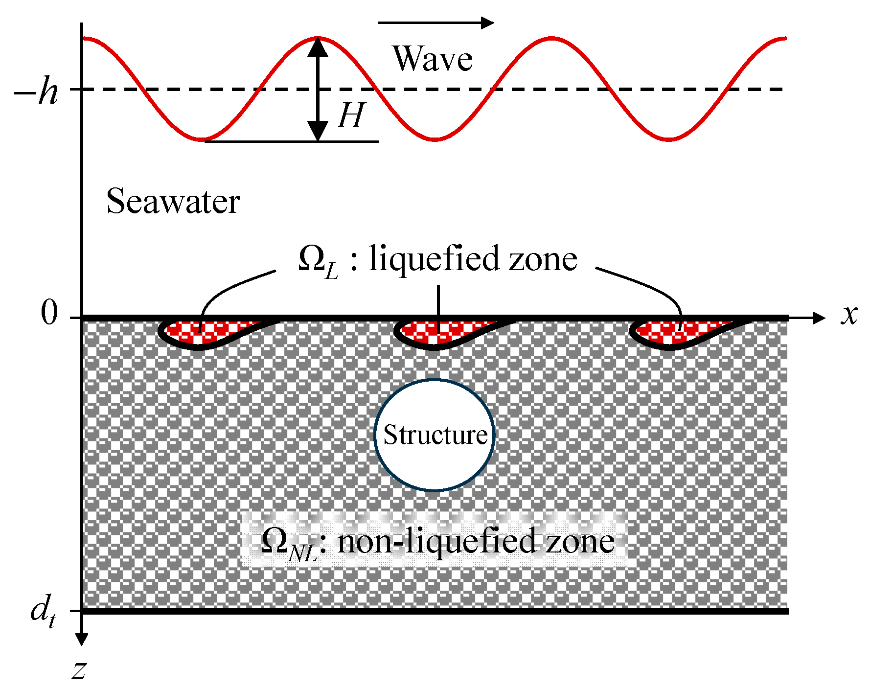
Figure 1. Simplified wave–seabed–structure model with instantaneous liquefaction.
Jmse 12 00373 g001
Figure 2. Schematic diagram of non-Darcy flow model.
Jmse 12 00373 g002
Figure 3. A schematic of the experiment by Turcotte [67].
Jmse 12 00373 g003
Figure 4. A comparison of the wave-induced pore pressure amplitude along the periphery of the fully buried pipeline between laboratory data by Turcotte [67] and numerical simulations by Cheng and Liu [72]: (a) T = 0.9 s, H = 5.24 cm; (b) T = 1.75 s, H = 14.3 cm; (c) T = 2.3 s, H = 3.02 cm.
Jmse 12 00373 g004
Figure 5. p P b versus depth along the x-directional centerline.
Jmse 12 00373 g005
Figure 6. Pore pressure versus time step along the x-directional centerline at different depths.
Jmse 12 00373 g006
Figure 7. Schematic diagram of model grid.
Jmse 12 00373 g007
Figure 8. Pore pressure versus time step at the top position of the pipeline under Scheme I.
Jmse 12 00373 g008
Figure 9. Pore pressure versus depth above the top position of the pipeline under Scheme I.
Jmse 12 00373 g009
Figure 10. Pore pressure versus time step at the top position of the pipeline under Scheme II.
Jmse 12 00373 g010
Figure 11. Pore pressure versus depth above the top position of the pipeline under Scheme II.
Jmse 12 00373 g011
Figure 12. Pore pressure versus time step at the top position of the pipeline under Scheme III.
Jmse 12 00373 g012
Figure 13. Pore pressure versus depth above the top position of the pipeline under Scheme III.
Jmse 12 00373 g013
Figure 14. Liquefaction zones from CP and ND models in Schemes I~III: (a) from CP model in Scheme I; (b) from ND model in Scheme I; (c) from CP model in Scheme II; (d) from ND model in Scheme II; (e) from CP model in Scheme III; (f) from ND model in Scheme III.
Jmse 12 00373 g014
Figure 15. Liquefaction zones obtained by CP and ND models in the scheme of d = D = 0.168 m: (a) CP model; (b) ND model; (c) vertical distribution of γ z p P b .
Jmse 12 00373 g015aJmse 12 00373 g015b
Figure 16. Liquefaction depth versus (a) Young’s modulus 𝐸; (b) permeability coefficient k s ; (c) saturation degree S r ; (d) soil porosity 𝑛; (e) water depth h; (f) wave period 𝑇; (g) wave height 𝐻. (h) z ND versus z CP .
Jmse 12 00373 g016
Figure 17. Liquefaction zones: (a) H = 0.6 m without a pipeline; (b) H = 0.8 m without a pipeline; (c) H = 0.6 m with a pipeline; (d) H = 0.8 m with a pipeline.
Jmse 12 00373 g017
Figure 18. z ND / d versus L/D in ND model.
Jmse 12 00373 g018
Figure 19. (a) Liquefaction shielding phenomenon above the pipeline; liquefied zones when (b) d = 0.084 m; (c) d = 0.2 m; (d) d = 0.25 m.
Jmse 12 00373 g019aJmse 12 00373 g019b
Figure 20. A schematic diagram of flow around the pipeline.
Jmse 12 00373 g020
Figure 21. Liquefaction depth versus d/D.
Jmse 12 00373 g021
Table 1. Computational parameters for the model with seabed liquefaction.
ParameterT (s)L (m)H (m)h (m) S r (-)n (-)γ′ (kN/m3) k s (m·s−1)E (MPa) ν (-)
Value25.210.610.950.4255.30.00130.33
Table 2. Computational schemes with various buried depths and diameters.
Scheme No.Burial Depth d (m)Diameter D (m)
I0.0420.042
II0.0840.084
III0.1260.126
Table 3. The scheme of the burial depth and diameter.
D (m)d = D (m)d = 2D (m)d = 3D (m)d = 4D (m)d = 5D (m)
0.0420.0420.0840.1260.1680.21
0.0840.0840.1680.2520.3360.42
0.1260.1260.2520.3780.5040.63
0.1680.1680.3360.5040.6720.84
Table 4. Liquefaction depth under different working schemes.
D (m)d (m)d/DLiquefaction Depths (m)
0.0840.33.60.06
0.2530.06
0.22.40.055
0.151.80
0.08410
0.1260.352.80.06
0.32.40.06
0.2520.055
0.21.60.05
0.151.1904760
0.0840.6666670
0.1680.42.3809520.06
0.31.7857140.06
0.251.4880950.05
0.21.1904760.05
0.150.8928570
0.0840.50
Disclaimer/Publisher’s Note: The statements, opinions and data contained in all publications are solely those of the individual author(s) and contributor(s) and not of MDPI and/or the editor(s). MDPI and/or the editor(s) disclaim responsibility for any injury to people or property resulting from any ideas, methods, instructions or products referred to in the content.