Article

Analysis of Unsteady Flow Characteristics Near the Cutwater by Cutting Impeller Hub in a High-Speed Centrifugal Pump

Key Laboratory of Fluid Transmission Technology of Zhejiang Province, Zhejiang Sci-Tech University, Hangzhou 310018, China
*
Author to whom correspondence should be addressed.
J. Mar. Sci. Eng. 2024, 12(4), 587; https://doi.org/10.3390/jmse12040587
Submission received: 6 March 2024 / Revised: 25 March 2024 / Accepted: 28 March 2024 / Published: 29 March 2024
(This article belongs to the Section Ocean Engineering)

Abstract

:
Centrifugal pumps are essential fluid transfer devices in marine engineering. As the two most critical components of a centrifugal pump, the dynamic–static interference between the volute and the impeller makes the flow near the cutwater highly unstable, with significant and erratic pressure pulsation, which seriously affects the stability of the operation. The impeller can be improved by cutting the hub, which helps stabilize the flow and reduce pressure pulsation near the cutwater, thus minimizing hydraulic loss. In this study, four different cutting angles were applied to the impeller hub. Computations are conducted using large eddy simulation to analyze the flow and pressure pulsation near the cutwater. Compared to the prototype pump, the modified impeller exhibits a significant reduction in pressure gradient near the blade outlet close to the cutwater. The modified impeller also shows a more uniform flow and lower amplitude of pressure pulsation. Furthermore, under various flow conditions, the centrifugal pump with the modified impeller exhibits lower hydraulic loss compared to the prototype pump, indicating that this method effectively suppresses hydraulic loss.

1. Introduction

Centrifugal pumps are essential fluid transfer equipment in marine engineering, widely utilized in fields such as deep-sea mining and seawater desalination. With the increase in extreme application environments, the performance indicators, design requirements, and operational stability of pumps are becoming increasingly stringent [1,2,3,4]. The dynamic–static interference between the impeller blades and the cutwater can easily lead to complex unsteady flow structures such as secondary flows and vortices [5]. Therefore, optimizing the design of the impeller and studying the relationships between internal flow, pressure pulsation, and hydraulic loss in high-speed centrifugal pumps are of significant importance for ensuring the safe and stable operation of these systems [6,7,8,9,10,11].
Many researchers have optimized the performance of centrifugal pumps by altering the geometric parameters of the impeller and conducting simulations through numerical modeling. Byskov et al. [12]. conducted experimental research on the full-flow conditions of centrifugal pumps and performed numerical calculations using large eddy simulation and multiple turbulence models. They found that the large eddy simulation captured the internal flow details and complex flow phenomena of the pump accurately. Li et al. [13] analyzed the flow characteristics between the blade outlet and the diffuser inlet for impellers with different blade trailing edge shapes. Wang et al. [14] conducted an analysis on the influence of T-shaped blades on the performance of centrifugal pumps. The results showed that using T-shaped blades can reduce hydraulic loss, increase Euler head, and improve external characteristics. Qu et al. [15] proposed an unconventional parabolic impeller trimming method. The results showed that this method can improve the flow at the impeller outlet. Ding et al. [16] studied the influence of five different blade outlet angles on the pump head and efficiency. The results showed that an increase in the blade outlet angle led to increased hydraulic losses, particularly affecting the efficiency at high flow rates. Liu et al. [17] found that reducing the blade outlet angle while increasing the wrap angle improved the flow conditions and pressure distribution in the impeller and volute, resulting in a significant improvement in the efficiency of the centrifugal pump. Gu et al. [18] performed modifications on the shroud of the impeller in a multi-stage centrifugal pump and observed that the modified design resulted in a reduction in axial forces and a decrease in energy loss.
The unsteady interaction between the impeller and the cutwater, along with the disturbances caused by vortex shedding, can result in periodic pressure fluctuations within the centrifugal pump over time [19,20,21]. Yan et al. [22] revealed that the implement of splitter blades was effective in mitigating unstable pressure fluctuations at the cutwater and reducing the formation of trailing vortex structures at the impeller outlet. Luo et al. [23,24] studied the vortex characteristics and unsteady flow behavior near the impeller tongue of a centrifugal pump. Peng et al. [25] optimized the blade parameters using the response surface methodology and found that after the modification, there was a significant reduction in large-scale vortices within the impeller flow passage. Zhang et al. [26] used large eddy simulation (LES) to analyze the interaction between the static and rotating components and the flow structure in a low specific speed centrifugal pump. The results showed that due to the interaction between static and rotating components, the unsteady vortex structures near the cutwater exhibited more significant pressure fluctuations compared to other regions. Jiang et al. [27] investigated the influence of the position between the impeller blades and the cutwater on the unsteady pressure fluctuations in a centrifugal pump. When the blade was close to the cutwater, the fluctuation intensity of the pressure was relatively lower, and the radial forces on the impeller were higher. Lu et al. [28] studied the characteristics of pressure fluctuations at the cutwater, where pressure fluctuations were mainly influenced by the separation vortex and dynamic–static interference. Ding et al. [29] found that blade trimming significantly reduced pressure pulsation and improved internal flow in centrifugal pumps.
Despite extensive research on the impact of impeller optimization on internal flow in centrifugal pumps, there is relatively limited research on different cutting angles of the impeller hub. Considering the significant effect of blade shape on centrifugal pumps, the approach of cutting the impeller hub attempts to reduce unstable flow and hydraulic loss. Although we have analyzed the pressure fluctuations of impellers with hub-cutting angles of 0°, 15°, 30°, and 45° using the SST k-ε model [30], the flow and pressure pulsation near the cutwater at different flow rates have not been thoroughly investigated. In this study, the flow and hydraulic loss near the cutwater are investigated using large eddy simulation. This research provides references for impeller design and is an important approach to improve internal flow and reduce hydraulic loss.

2. Geometric and Mesh Generation

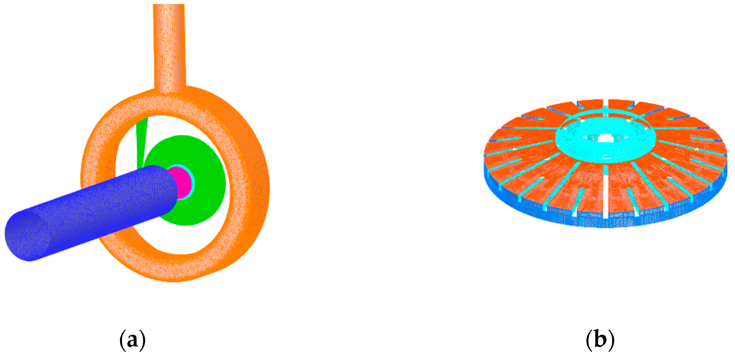
2.1. Geometric Model

The model used in this paper is a high-speed pump with an inducer. The internal flow medium is water. The fluid domain was modeled by using SolidWorks2018, and the flow passage model is shown in Figure 1. The main components include the inlet extension, diffuser section, inducer, impeller, volute, diffuser section, and outlet extension. The main design parameters are Qd = 12 m3/h, Hd = 2153 m, and n = 23,350 rpm. The other design parameters of the centrifugal pump are shown in Table 1. The model of the impeller and the cutting scheme of the impeller hub are shown in Figure 2. The cutting method is to cut at the interface position of the blade and the hub, and the maximum angle is 45° to prevent the impeller strength from being affected by the cutting angle. The prototype impeller in this model is named PB and is a semi-open impeller with 12 main blades as well as 12 splitter blades. The cutting schemes involve cutting the impeller hub at angles of 15°, 30°, and 45°, named BHC15, BHC30, and BHC45, respectively.

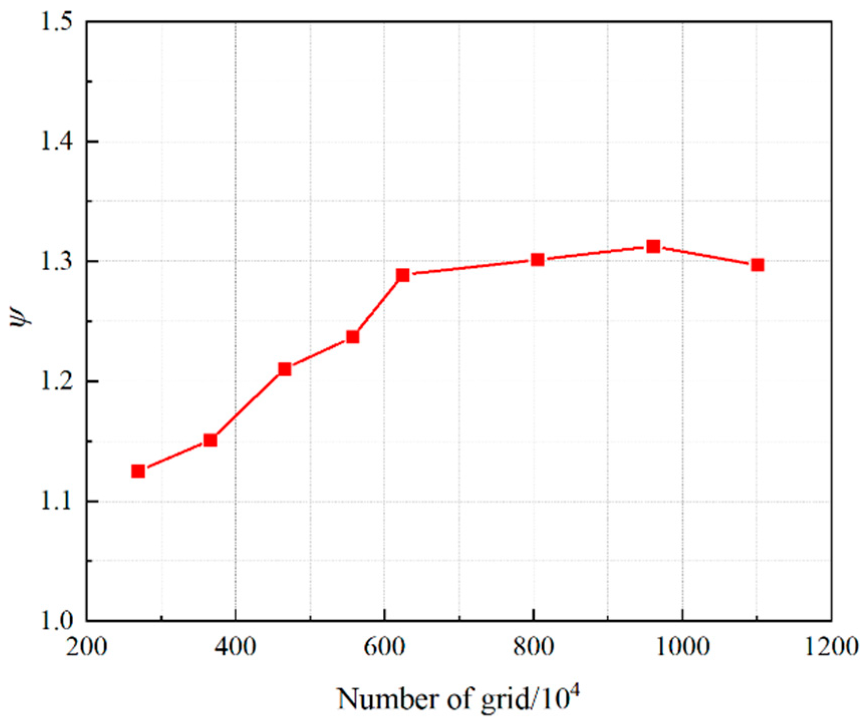
2.2. Mesh Generation and Numerical Simulation Method

This paper uses ICEM18.0 to mesh the fluid domain. The number of mesh elements has a significant impact on computational speed and accuracy. In this article, eight sets of meshes are selected for grid independence verification at the design flow rate. The head coefficient is used as the evaluation criterion, and it is considered satisfactory when its variation is less than 0.5%. The relationship between the quantity of grids and the computed head coefficient curve is shown in Figure 3. Finally, ensuring that the mesh quantity meets the requirements of simulation accuracy and computational demands, a total of 9.6 × 1026 mesh elements is chosen. The impeller is meshed using hexahedral structured grids, while complex computational domains such as the volute casing use unstructured grids. The entire fluid computational domain and the impeller mesh are shown in Figure 4.
The head coefficient refers to the relationship between the head provided by the pump and parameters such as speed, impeller diameter, and suction diameter as the flow rate changes during the operation of the pump. The calculation formula for the head coefficient is as follows [31]:
ψ = 2 g H u 2 2
The LES turbulence model filters the Navier–Stokes equations to obtain the large eddies containing the main scalar quantities and the small eddies smaller than the filter width. The governing equation for the large eddies can be expressed as follows [31]:
ϕ ¯ ( x i ) = ϕ ( ξ i ) H ¯ ( x i ξ i , Δ ) d ξ i
In the equation, H ¯ is the filtering function.
The filtered governing equation after the filtering operation is the following:
u i ¯ t + u j ¯ u i ¯ x j = 1 ρ p ¯ x i ¯ + ν 2 u i ¯ x j x j + τ i j ¯ x j
u i ¯ x i = 0
In this equation, τ i j ¯ represents the momentum exchange between the large and small-scale fluctuations, and its expression is the following:
τ i j ¯ = u i ¯ u j ¯ u i u j ¯
This paper adopts the Smagorinsky–Lilly model, and its expression is as follows:
τ i j 1 3 τ k k δ i j = 2 ( C s Δ ) 2 | S ¯ | S i j
μ sgs = ρ ( C s Δ ) 2 | S ¯ |
In the equation, Cs takes values between 0.1 and 0.2. The eddy viscosity μ eff is given by the following:
μ eff = μ mol + μ sgs
The inlet boundary condition selects the pressure inlet, and the outlet boundary condition selects the mass flow outlet. The turbulence intensity is 5%, and the hydraulic diameter is 82 mm. The impeller and the inducer have rotating wall surfaces, while the remaining walls are stationary. All wall surfaces are assumed to be smooth with no-slip conditions.

2.3. Eternal Characteristic Analysis

The experimental system diagram is shown in Figure 5, and the uncertainty analysis is shown in Table 2. The characteristic curves obtained from numerical simulation and experimental data are shown in Figure 6. Comparing the results, it can be observed that with an increase in flow rate, there is a corresponding decrease in the head as well as an increase in efficiency. The numerical simulation and experimental trends are consistent. The numerically simulated head coefficient is 1.283 with an efficiency of 27.15%, while the experimentally obtained head coefficient is 1.275 with an efficiency of 26.11%. The errors in both cases are within 5%, demonstrating the accuracy of the numerical simulation.
The characteristic curves of the four modified centrifugal pumps are shown in Figure 5. The modified high-speed centrifugal pumps exhibit an increase in head compared to the prototype design. At the design flow rate, the head coefficients for the PB, BHC15, BHC30, and BHC45 pumps are 1.283, 1.288, 1.293, and 1.297, respectively. The efficiencies for the PB, BHC15, BHC30, and BHC45 pumps are 26.4%, 26.9%, 27.0%, and 27.1%, respectively.
Due to the presence of uncontrollable external factors that can introduce errors into experimental results, this study conducted five sets of experiments under standard operating conditions and performed uncertainty analysis. The head coefficients obtained in five groups of experiments are shown in Table 2. The uncertainty σ is not higher than 0.5, which shows that the experiment is of high quality. The standard uncertainty σ is calculated by Bessel’s formula [31]:
σ = i = 1 n ( ψ i ψ ¯ ) 2 n 1 = 0.018 < 0.5
where n is experimental number, ψ is the experimental head coefficient, and ψ ¯ is the average experimental head coefficient.

3. Internal Flow Analysis

3.1. Static Pressure Analysis

The high-speed pump studied in this paper has a high speed and can produce a higher head, and its outlet pressure reaches 107 Pa. In a period, the average outlet pressure obtained in the experiment is 11.478 MPa, and the average outlet pressure obtained in the simulation is 11.542 MPa. In order to study the effect of different cutting angles of the impeller hub on the internal flow characteristics of the centrifugal pump, the static pressure coefficient Cp is introduced for analysis. The static pressure coefficient is used to describe the pressure characteristics and is defined as follows [32]:
C p = P P in 1 2 ρ u 2 2
In the equation, u2 represents the velocity at the impeller outlet, in m/s. P represents the average static pressure at a certain section, in Pa. Pin represents the average static pressure at the impeller inlet section, in Pa. ρ represents the density of the fluid, in kg/m3.
Figure 7 shows the distribution of static pressure coefficients near the cutwater for different cutting angles of the impeller hub at three flow conditions in the centrifugal pump. The fluid flow process inside the high-speed centrifugal pump gradually increases the pressure from the impeller inlet to the outlet. As shown in Figure 6, the small flow area near the cutwater prevents some fluid from entering the volute, resulting in flow separation, vortices, secondary flows, and other flow structures. These are reflected in the static pressure contour plot as localized high- and low-pressure regions near the cutwater, causing large pressure gradients. Compared to the design flow condition, the static pressure coefficients in the inlet region of the volute 1 are higher for low-flow conditions and lower for high-flow conditions, which is consistent with the head characteristics observed in the performance curves. The middle section static pressure coefficients after cutting the impeller hub are slightly higher than those of the original pump for all flow conditions, which is also in line with the corresponding head characteristics of the modified centrifugal pump. This indicates that cutting the impeller hub can improve the internal static pressure distribution and enhance the performance of the centrifugal pump.

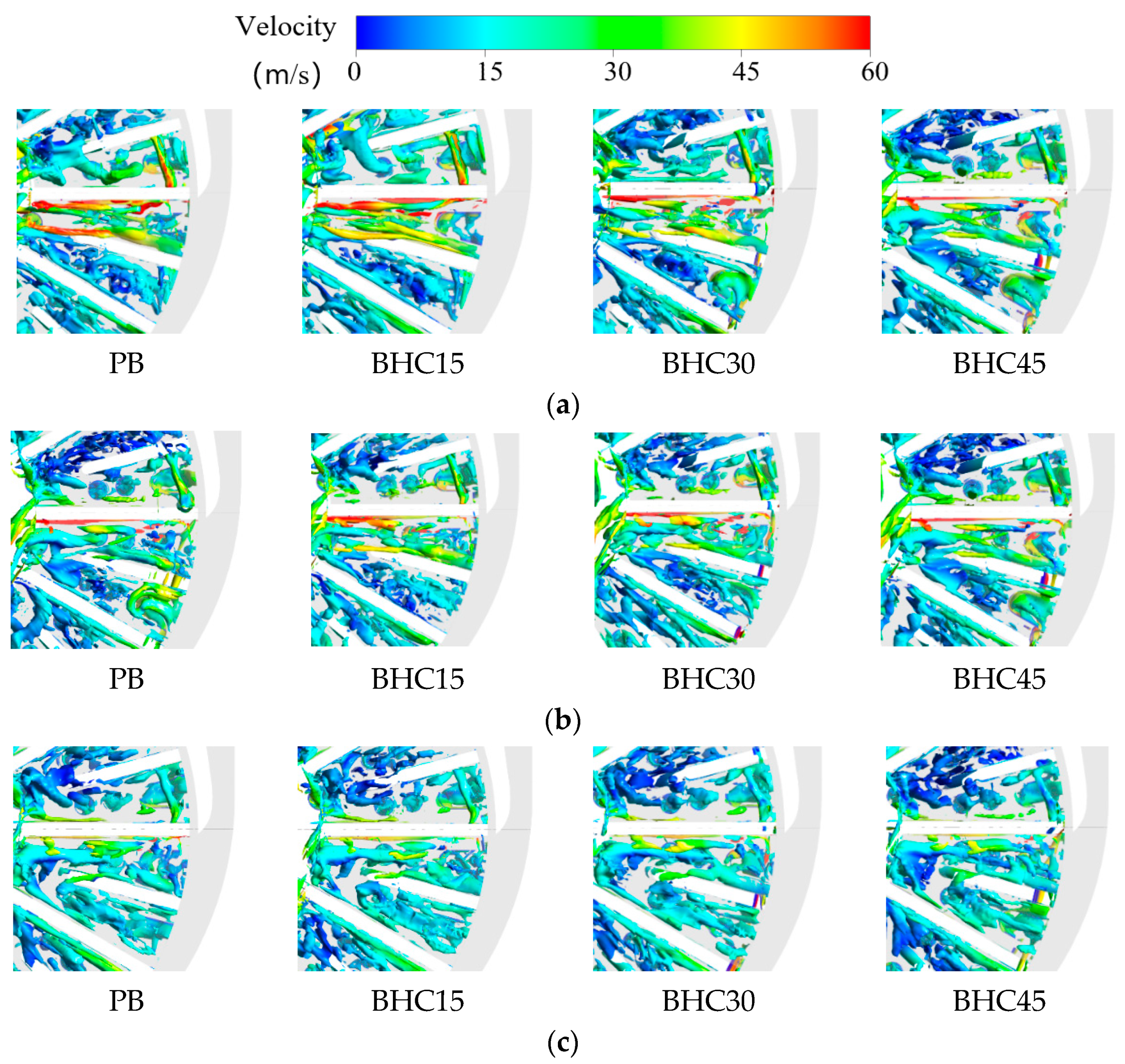
3.2. Vortex Distribution Analysis

The internal vortex morphology and structural evolution within the impeller domain have a certain influence on its pressure and velocity distribution, leading to disturbances in the internal flow field characteristics such as pressure and streamline. During the operation of a high-speed centrifugal pump, vortices will inevitably be generated within the impeller flow passage. The formation of these vortices increases the instability and complexity of the fluid during the flow process. This study captures the location of vortices through the analysis of vorticity. Currently, the main methods for characterizing vortex structures are vorticity, Q-criterion, and Ω-criterion. In this study, the Ω-criterion is used to investigate the spatial evolution of vortices inside the impeller. The definition of the Ω-criterion is as follows [32]:
Ω = ( × V · R ) 2 × V 2 2 R 2 2
In the formula, Omega vortices are characterized by velocity coloring.
From Figure 8, it can be observed that there are numerous vortex structures at the cutwater of the impeller flow passage for each flow condition. This is due to the complex structural design of the pump impeller and the strong turbulence caused by the interaction between the rotating and stationary components. Under low-flow conditions, the modified impeller exhibits a certain reduction in high-speed vortex structures near the cutwater compared to the original pump. For the remaining flow conditions, there is little difference in the pump with four cutting angles of the impeller hub, indicating that the modified impeller has some improvement in the distribution of Omega vortices compared to the original pump under low-flow conditions. As the flow rate increases, there is a decrease in the vortex structures in the impeller flow passage near the cutwater.

3.3. Velocity Streamline Analysis

The distribution of relative velocity flow lines and vorticity in the flow passage near the cutwater of pump impellers with four cutting angles under the design flow rate is shown in Figure 9. The upper part of the CH channel for impellers with different cutting angles is filled with backflow due to cutwater interference. In the upper part of the CH channel, the fluid flows in the opposite direction to the backflow, resulting in a low-speed reverse vortex. In the lower part of the CH channel, vortices are formed due to friction between the fluid and the wall. The BHC45 pump exhibits a significant reduction in vortices compared to the prototype pump, indicating that the BHC45 high-speed pump can improve wake flow and achieve a more uniform outlet flow at the impeller under the design flow condition.
Under low flow conditions, the vorticity in the CH channel is larger compared to the design flow condition. The vortex core is closer to the impeller outlet and occupies the lower half of the entire CH channel, resulting in a more complex and unstable internal flow. The modified centrifugal pump shows a reduction in vorticity compared to the prototype pump. This is because the flow field in the lower part of the CH channel is more uniform, allowing the smoother re-entry of backflow from the upper part into the volute through the lower part.
Under high flow conditions, the vorticity in the CH channel is smaller compared to the design flow condition. The flow lines under high flow rates differ significantly from those under low flow rates and the design flow rate. Most of the vortices are concentrated in the upper part of the CH channel. This is because there is more backflow in the upper part of the CH channel, generating vortices with the fluid developed from the inlet itself, while there is less backflow that can reach the lower part of the CH channel, resulting in almost no formed backflow vortices in the lower part.
Compared to the prototype impeller, the modified impeller of the centrifugal pump exhibits a more uniform flow and a smaller area of backflow vortex at the outlet. The high-speed pump BHC45 shows a minimal formation of large backflow vortices throughout the CH channel area, indicating that cutting the impeller back cover significantly improves the impeller flow.

3.4. Pressure Pulsation Analysis

In order to analyze the pressure pulsation near the cutwater of the centrifugal pump, a monitoring point was placed at the cutwater position of the centrifugal pump. The location of this monitoring point is shown in Figure 10.
The time domain of pressure pulsation coefficients near the cutwater of centrifugal pumps with different cutting angles impellers are shown in Figure 11 at various flow rates. The pressure pulsation near the cutwater exhibits poor periodicity, with erratic and fluctuating patterns. Under the design flow condition, 12 large peaks can be observed, with less prominent small peaks between each large peak. This indicates that the pressure pulsation near the cutwater is primarily influenced by the main impeller blades, while the effect of the splitter blades is less significant. Under low-flow conditions, 24 peaks can be observed, indicating that the pressure pulsation near the cutwater is influenced by both the main impeller blades and the splitter blades. Under high-flow conditions, the pattern is similar to the design flow condition, with 12 large peaks present, indicating that the pressure pulsation near the cutwater is similarly influenced by the main impeller blades.
Pressure pulsation coefficients frequency domain near the cutwater of modified centrifugal pumps, obtained through the FFT Algorithm, are shown in Figure 11. Under the design condition, the main frequency of the pressure pulsation near the cutwater is 4669.71 Hz, which is consistent with the main blade frequency. The subharmonic frequency is 1555.90 Hz, which is four times the shaft frequency. In the frequency range above the main frequency, some frequency domain fluctuations can also be observed at the harmonic positions. At the main frequency position, the amplitudes of the high-speed pumps are 0.01627, 0.01322, 0.01491, and 0.01106, respectively. At the main frequency, the high-speed pumps (BHC15, BHC30, BHC45) exhibit decreases in pressure pulsation of 18.7%, 8.3%, and 32.0%, respectively. Under other flow conditions, the main frequency amplitude for the centrifugal pump with a cutting hub is reduced. It shows that the modified impeller has a certain suppressive effect on the pressure fluctuation near the cutwater.

4. Hydraulic Loss Analysis

In practical engineering applications, empirical formulas are commonly used to predict the hydraulic loss inside centrifugal pumps. Hydraulic losses include impeller inlet impact loss, impeller passage friction loss, impeller passage diffusion loss, and impeller outlet dynamic and static interference loss. Based on the aforementioned flow analysis and pressure pulsation analysis, the main causes of hydraulic losses are friction losses from the impeller passage and loss from the impeller outlet dynamic and static interference. Therefore, this study focuses on the calculation and analysis of these two types of hydraulic loss.

4.1. Impeller Passage Friction Loss

In numerical calculations, wall surfaces are typically assumed to be frictionless walls. However, in practical pump operation, wall friction is unavoidable. Especially for centrifugal pumps that have been in operation for a long time, the pump surfaces can become rough due to cavitation and other factors, leading to significant hydraulic losses and affecting the pump’s performance. The calculation formula for these losses is as follows [33]:
Δ h 2 = k 2 × Z × λ × l a D a × W a 2 2 g
Da is the average diameter; ns is the specific speed, which is 82.3; W1 and W2 are the relative velocities at the inlet and outlet of the impeller; la is the length of the passage;  k 2 = ( 4.68 n s 0.0185 4.84 ) 1 = 4.20 is the loss coefficient; Z is the number of impeller blades; λ is the friction resistance coefficient; and Wa is the average relative velocity, calculated as Wa = 0.5(W1 + W2).
Figure 12 shows the distribution of impeller passage friction loss for centrifugal pumps with different cutting angles of the hub under three flow rate conditions. It can be observed that the friction losses in the impeller passages are significant, accounting for approximately 10% of the pump head. This is due to the complex structural design of high-speed centrifugal pump impellers, which leads to intense turbulence within the impeller passages. These passages are filled with numerous vortex structures, resulting in significant friction losses. As the flow rate increases, the friction losses in the impeller passages also increase. The different cutting angles of the hub have varying effects on the friction losses in the impeller passage, with a reduction in friction loss observed for the impeller with a cutting hub compared to the prototype pump PB. Under the design condition, the impeller passage friction losses for the PB, BHC15, BHC30, and BHC45 high-speed pump are 217.13 m, 199.91 m, 199.90 m, and 177.47 m, respectively. The modified centrifugal pumps exhibit a reduction in impeller passage friction losses compared to the prototype pump by 7.93%, 7.93%, and 18.26%, respectively. Among them, the BHC45 high-speed pump has the lowest passage friction loss at all flow rates.

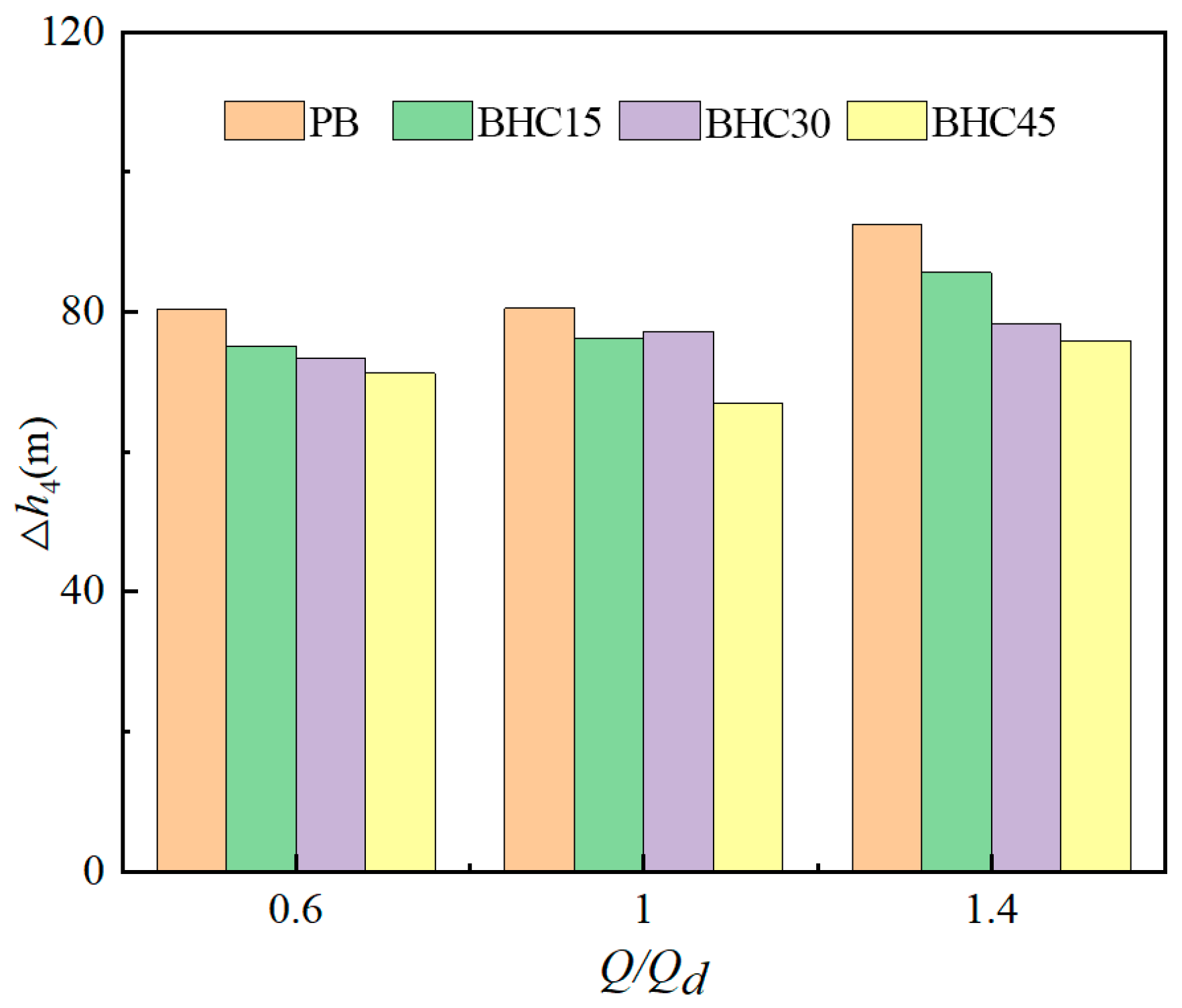
4.2. Dynamic and Static Interference Loss

The dynamic and static interference between the impeller and the volute casing results in significant dynamic and static interference loss. The calculation formula for the loss is as follows [33]:
Δ h 4 = k 4 × V m 2 2 + ( V θ 2 2 V s 2 ) 2 g
k 4 = 0.00025 + 0.87 ( n s 100 ) + 0.5 ( n s 100 ) 2 2.44 ( n s 100 ) 3 = 0.92
Vm2 is the axial velocity at the impeller outlet, and Vs is the average velocity near the cutwater of the volute casing.
Figure 13 shows the distribution of dynamic and static interference loss at the outlet of the impeller for modified centrifugal pumps under varying flow rate conditions. It can be observed that the dynamic and static interference loss at the impeller outlet is significant, accounting for approximately 5% of the total head. This is due to the small clearance near the cutwater, which creates complex three-dimensional flow phenomena such as separation vortices and secondary flows, affecting the fluid flow and causing significant dynamic and static interference loss. As the flow rate increases, the dynamic and static interference loss at the impeller outlet also increases. The different cutting angles of the hub have varying effects on the dynamic and static interference losses at the exit of the impeller, with a reduction in loss observed for the modified impeller. This reduction is attributed to a more uniform backflow near the cutwater of the impeller passage after cutting the hub.

5. Conclusions

This article analyzes flow and pressure pulsation near the cutwater of centrifugal pumps with different cutting angles of the hub under different flow rates. Based on this analysis, empirical formulas are used to analyze the various types of hydraulic loss generated by the impeller of the centrifugal pump. This research can provide guidance for the optimal design of centrifugal pumps at similar specific speeds. The main conclusions are as follows:
  • Cutting the hub of the impeller can improve the static pressure distribution and vortex distribution near the cutwater of the centrifugal pump. It also results in a more uniform velocity streamline distribution near the cutwater. Additionally, the modified centrifugal pump shows certain improvements in the Omega vortex distribution compared to the prototype pump PB.
  • The modified centrifugal pump exhibits a reduced amplitude of pressure pulsation in the frequency domain compared to the prototype pump at various flow conditions. Cutting the hub of the impeller has a certain suppressive effect on the pressure pulsation at the cutwater of the centrifugal pump. In conclusion, cutting the hub of the impeller can enhance the performance of the centrifugal pump.
  • By applying empirical formulas to calculate the hydraulic loss of the centrifugal pump, it was found that the impeller passage friction loss and the dynamic and static interference loss were the main sources of hydraulic loss. Cutting the hub of the impeller had a certain inhibitory effect on the hydraulic loss.

Author Contributions

Methodology and validation, M.S. and B.C.; formal analysis, M.S. and B.C.; writing—review and editing, M.S. and B.C. All authors have read and agreed to the published version of the manuscript.

Funding

The authors would like to acknowledge the financial support from the National Natural Science Foundation of China (Grant No. U22A20209 and No. 52076197) and the Key Research and Development Program of Zhejiang Province (Grant No. 2022C01067).

Institutional Review Board Statement

Not applicable.

Informed Consent Statement

Not applicable.

Data Availability Statement

The data presented in this study are available on request from the corresponding author. Due to the huge amount of data, it is not convenient to save to publicly archived datasets.

Conflicts of Interest

The authors declare no conflicts of interest.

Nomenclature

QdDesign flow rate
HdHead
nRotating speed
nsSpecific speed
Z1Main blade
DsPump inlet diameter
DOPump outlet diameter
D1Impeller inlet diameter
D2Impeller outlet diameter
b1Impeller Inlet width
b2Impeller Exit width
u2The velocity at the impeller outlet
PThe average static pressure at a certain section
PinThe average static pressure at the impeller inlet section
ρThe density of the fluid
DaThe average diameter
W1The relative velocities at the inlet of the impeller
W2The relative velocities at the outlet of the impeller
laThe length of the passage
ZThe number of impeller blades
λThe friction resistance coefficient
Vm2The axial velocity at the impeller outlet
nsThe specific speed
VsThe average velocity near the cutwater of the volute casing

References

  1. Zhang, Y.; Song, D.; Wang, H.; Wang, X.; Jiang, L.; Wang, C.; Fan, M.; Zhao, J. Performance fluctuations and evaluation of a piston type integrated high pressure pump-energy recovery device. NPJ Clean. Water 2022, 5, 19. [Google Scholar] [CrossRef]
  2. Hou, H.; Zhang, Y.; Zhou, X.; Zuo, Z.; Chen, H. Optimal hydraulic design of an ultra-low specific speed centrifugal pump based on the local entropy production theory. Proc. Inst. Mech. Eng. Part A J. Power Energy 2019, 233, 715–726. [Google Scholar] [CrossRef]
  3. Hu, Q.; Chen, J.; Deng, L.; Kang, Y.; Liu, S. CFD-DEM Simulation of Backflow Blockage of Deep-Sea Multistage Pump. J. Mar. Sci. Eng. 2021, 9, 987. [Google Scholar] [CrossRef]
  4. Lu, J.; Yan, W.; Tao, R.; Wang, Z.; Zhu, D. Exploring the Mechanism of Strong-Pressure Fluctuation under Partial Load in the Turbine Mode of Pump Turbines for Hydro and Marine Power Storage. J. Mar. Sci. Eng. 2023, 11, 1089. [Google Scholar] [CrossRef]
  5. Jia, X.; Cui, B.; Zhu, Z.; Yu, X. Numerical investigation of pressure distribution in a low specific speed centrifugal pump. J. Therm. Sci. 2018, 27, 25–33. [Google Scholar] [CrossRef]
  6. Lin, Y.; Li, X.; Zhu, Z. An energy consumption improvement method for centrifugal pump based on bionic optimization of blade trailing edge. Energy 2022, 246, 123323. [Google Scholar] [CrossRef]
  7. Ji, L.; Li, W.; Shi, W. Effect of blade thickness on rotating stall of mixed-flow pump using entropy generation analysis. Energy 2021, 236, 121381. [Google Scholar] [CrossRef]
  8. Zhang, F.; Appiah, D.; Hong, F. Energy loss evaluation in a side channel pump under different wrapping angles using entropy production method. Int. Commun. Heat. Mass. 2020, 113, 104526. [Google Scholar] [CrossRef]
  9. Li, X.; Chen, B.; Luo, X. Effects of flow pattern on hydraulic performance and energy conversion characterization in a centrifugal pump. Renew. Energ. 2020, 151, 475–487. [Google Scholar] [CrossRef]
  10. Yang, Y.; Zhou, L.; Hang, J. Energy characteristics and optimal design of diffuser meridian in an electrical submersible pump. Renew. Energy 2021, 167, 718–727. [Google Scholar] [CrossRef]
  11. Hirano, T.; Guo, Z.; Kirk, R.G. Application of computational fluid dynamics analysis for rotating machinery—Part ii: Labyrinth seal analysis. J. Eng. Gas. Turbines Power 2005, 127, 820–826. [Google Scholar] [CrossRef]
  12. Byskov, R.K.; Jacobsen, C.B.; Pedersen, N. Flow in a centrifugal pump impeller at design and off-design conditions—Part II: Large eddy simulations. J. Fluids Eng. 2003, 125, 73–83. [Google Scholar] [CrossRef]
  13. Li, H.; Chen, Y.; Yang, Y.; Wang, S.; Bai, L.; Zhou, L. CFD Simulation of Centrifugal Pump with Different Impeller Blade Trailing Edges. J. Mar. Sci. Eng. 2023, 11, 402. [Google Scholar] [CrossRef]
  14. Wang, L.-k.; Lu, J.-l.; Liao, W.-l.; Guo, P.-c.; Feng, J.-j.; Luo, X.-q.; Wang, W. Numerical investigation of the effect of T-shaped blade on the energy performance improvement of a semi-open centrifugal pump. J. Hydrodyn. 2021, 33, 736–746. [Google Scholar] [CrossRef]
  15. Qu, X.; Wang, L. Effects of impeller trimming methods on performances of centrifugal pump. J. Energ. Eng. 2016, 142, 04016008. [Google Scholar] [CrossRef]
  16. Ding, H.; Li, Z.; Gong, X. The Influence of Blade Outlet Angle on the Performance of Centrifugal Pump with High Specific Speed. Vacuum 2019, 159, 239–246. [Google Scholar] [CrossRef]
  17. Liu, H.; Jiang, L.; Wang, Y. Optimization and CFD performance analysis of an automotive coolant pump. Adv. Mech. Eng. 2022, 14, 16878132221081602. [Google Scholar] [CrossRef]
  18. Gu, Y.; Sun, H.; Wang, C.; Lu, R.; Liu, B.; Ge, J. Effect of Trimmed Rear Shroud on Performance and Axial Thrust of Multi-Stage Centrifugal Pump with Emphasis on Visualizing Flow Losses. ASME. J. Fluids Eng. 2024, 146, 011204. [Google Scholar] [CrossRef]
  19. Ji, D.; Lu, W.; Lu, L.; Xu, L.; Liu, J.; Shi, W.; Huang, G. Study on the Comparison of the Hydraulic Performance and Pressure Pulsation Characteristics of a Shaft Front-Positioned and a Shaft Rear-Positioned Tubular Pump Devices. J. Mar. Sci. Eng. 2022, 10, 8. [Google Scholar] [CrossRef]
  20. Shang, L.; Cao, J.; Wang, L.; Yu, S.; Ding, S.; Wei, Z.; Wang, Z.; Liu, X. Analysis of Flow and Runner Dynamic Response Characteristics under Pump Conditions of Variable-Speed Pump Turbine. J. Mar. Sci. Eng. 2023, 11, 1493. [Google Scholar] [CrossRef]
  21. Li, Y.; Su, H.; Wang, Y.; Jiang, W.; Zhu, Q. Dynamic Characteristic Analysis of Centrifugal Pump Impeller Based on Fluid-Solid Coupling. J. Mar. Sci. Eng. 2022, 10, 880. [Google Scholar] [CrossRef]
  22. Yan, P.; Chu, N.; Wu, D. Computational fluid dynamics-based pump redesign to improve efficiency and decrease unsteady radial forces. J. Fluid. Eng. 2016, 139, 011101. [Google Scholar] [CrossRef]
  23. Luo, Z.-Y.; Feng, Y.; Sun, X.-Y.; Gong, Y.; Lu, J.-X.; Zhang, X.-W. Research on the Unsteady Flow and Vortex Characteristics of Cavitation at the Tongue in Centrifugal Pump. J. Appl. Fluid. Mech. 2024, 17, 646–657. [Google Scholar] [CrossRef]
  24. Qixiang, H.; Yang, Y.; Weidong, S.; Weidong, C.; Yansheng, S. Cavitating Flow in the Volute of a Centrifugal Pump at Flow Rates Above the Optimal Condition. J. Mar. Sci. Eng. 2021, 9, 446. [Google Scholar] [CrossRef]
  25. Peng, G.; Lou, Y.; Yu, D.; Hong, S.; Ji, G.; Ma, L.; Chang, H. Investigation of Energy Loss Mechanism and Vortical Structures Characteristics of Marine Sediment Pump Based on the Response Surface Optimization Method. J. Mar. Sci. Eng. 2023, 11, 2233. [Google Scholar] [CrossRef]
  26. Zhang, N.; Yang, M.; Gao, B. Experimental and numerical analysis of unsteady pressure pulsation in a centrifugal pump with slope volute. J. Mech. Sci. Technol. 2015, 29, 4231–4238. [Google Scholar] [CrossRef]
  27. Jiang, W.; Li, G.; Liu, P. Numerical investigation of influence of the clocking effect on the unsteady pressure fluctuations and radial forces in the centrifugal pump with vaned diffuser. Int. Commun. Heat. Mass. 2016, 71, 164–171. [Google Scholar] [CrossRef]
  28. Lu, J.; Luo, Z.; Chen, Q.; Liu, X.; Zhu, B. Study on pressure pulsation induced by cavitation at the tongue of the volute in a centrifugal pump. Arab. J. Sci. Eng. 2022, 47, 16033–16048. [Google Scholar] [CrossRef]
  29. Ding, H.; Ge, F.; Wang, K.; Lin, F. Influence of Blade Trailing-Edge Filing on the Transient Characteristics of the Centrifugal Pump during Startup. Processes 2023, 11, 2420. [Google Scholar] [CrossRef]
  30. Cui, B.; Liu, J.-X.; Zhai, L. Analysis of the performance and pressure pulsation in a high-speed centrifugal pump with different hub-cutting angles. Mod. Phys. Lett. B 2023, 37, 2350117. [Google Scholar] [CrossRef]
  31. Cui, B.; Chen, H.; Zhu, Z.; Sun, L.; Sun, L. Optimization of low-temperature multi-stage submersible pump based on blade load. Phys. Fluids 2024, 36, 035157. [Google Scholar] [CrossRef]
  32. Cui, B.; Zhang, C.; Zhang, Y.; Zhu, Z. Influence of Cutting Angle of Blade Trailing Edge on Unsteady Flow in a Centrifugal Pump Under Off-Design Conditions. Appl. Sci. 2020, 10, 580. [Google Scholar] [CrossRef]
  33. Wang, C.; Yao, Y.; Yang, Y.; Chen, X.; Wang, H.; Ge, L.; Cao, W.; Zhang, Q. Automatic optimization of centrifugal pump for energy conservation and efficiency enhancement based on response surface methodology and computational fluid dynamics. Eng. Appl. Comp. Fluid. 2023, 17, 2227686. [Google Scholar] [CrossRef]
Figure 1. Geometry of centrifugal pump.
Jmse 12 00587 g001
Figure 2. Hub-cutting impellers. (a) PB; (b) BHC15; (c) BHC30; and (d) BHC45.
Jmse 12 00587 g002
Figure 3. Grid independence.
Jmse 12 00587 g003
Figure 4. Grid for the flow domain in high-speed centrifugal pump: (a) whole-fluid computational domain; (b) impeller.
Jmse 12 00587 g004
Figure 5. The schematic diagram of the experimental system.
Jmse 12 00587 g005
Figure 6. Performance curves of centrifugal pump: (a) performance curves of pumps with different hub-cutting impellers; (b) numerical simulation and experimental performance curve 3. Numerical method.
Jmse 12 00587 g006
Figure 7. Static pressure coefficient distribution near cutwater: (a) 0.6 Q; (b) 1.0 Q; (c) 1.4 Q.
Jmse 12 00587 g007
Figure 8. Vortex distribution of the impeller near the cutwater: (a) 0.6 Q; (b) 1.0 Q; (c) 1.4 Q.
Jmse 12 00587 g008
Figure 9. Velocity streamline distribution near the cutwater: (a) 0.6 Q; (b) 1.0 Q; (c) 1.4 Q.
Jmse 12 00587 g009
Figure 10. Monitoring point.
Jmse 12 00587 g010
Figure 11. Time domain and frequency domain of pressure pulsation: (a) 0.6 Q; (b) 1.0 Q; (c) 1.4 Q.
Jmse 12 00587 g011
Figure 12. Impeller passage friction loss under different flow rates.
Jmse 12 00587 g012
Figure 13. Dynamic and static interference loss under different flow rates.
Jmse 12 00587 g013
Table 1. Design and main geometrical parameters of the high-speed centrifugal pump.
ParameterValue
Design flow rate (m3/h)12
Head (m)2153
Rotating speed (r/min)23,350
Specific speed82.3
Main blade12
Pump inlet diameter(mm)82
Pump outlet diameter (mm)50
Impeller inlet diameter (mm)54
Impeller outlet diameter (mm)140
Impeller inlet width (mm)10
Impeller exit width (mm)4
Table 2. Experimental head coefficient.
Experimental NumberExperimental Head Coefficient
11.275
21.289
31.265
41.296
51.25
Disclaimer/Publisher’s Note: The statements, opinions and data contained in all publications are solely those of the individual author(s) and contributor(s) and not of MDPI and/or the editor(s). MDPI and/or the editor(s) disclaim responsibility for any injury to people or property resulting from any ideas, methods, instructions or products referred to in the content.

