Abstract
At present, numerous wall-climbing robots have been developed, and applied in ship manufacturing for weld detection to ensure safe navigation. Limited by rigid mechanical structure and complex detection, mostly existing robots are hardly to complete weld detection by using fluorescent magnetic particles. Based on permanent magnet adsorption, a wheeled wall-climbing robot is developed to realize the stable adsorption and flexible movement on ship wall. A detection mechanism is designed using a series and parallel flexible adaptation structure to keep cross yokes and detection area close for effective detection. A unified mechanical model is established by analyzing the angle between robot attitude and gravity, to solve safe adsorption and flexible movement for different detection conditions. Integrated the multisensor information and collaboration between control component, an automatic detection control workflow conforms to the standard process is proposed. Experiments show that the robot can move on curvature wall flexibly and stably, complete the weld detection with the standard process, and clearly display the shape and depth of the small defects (groove depth ≥ 30 μm) in standard specimen.
1. Introduction
The rapid development of the maritime shipping trade has led to a surge in the demand for ships, which has greatly stimulated the upgradation of the shipbuilding industry [1,2,3]. Many welds are used in segmental construction and hull closing, and rapid, ac-curate weld detection directly affects construction quality and maritime safety. At present, a common method is to rely on manual handheld detection devices, which has problems such as low efficiency and high danger, and the detection results cannot be digitally saved [4,5,6]. Therefore, developing a wall-climbing detection robot, which can stably move on a ship, complete weld detection conforming to standard process, and save the detection results digitally, has become an urgent demand for shipyards to improve production efficiency and ship quality [7,8,9].
Magnetic particle detection has become the most common method for weld detection because of high efficiency and sensitivity [10]. During fluorescent magnetic detection using a handheld cross yoke, the detectors need to reach the designated position, actively adjust the yoke to the adapt and close fit to detection area to meet the effective field strength of accurate detection through flexible hand actions, spray magnetic suspension and observe magnetic powder surge state, then judge the quality of weld, and finally push the yoke to next position and start cycle detection. Therefore, a climbing mechanism that can achieve precise and stable movement on ships, a flexible detection mechanism that can adapt to complex facades passively, and a detection workflow that conforms to the standard process are the foundations for efficient accurate weld detection by robots. So lots of research has been conducted, mainly in three areas: moving mechanisms with safe adsorption and flexible movement, detection mechanisms that can flexibly adapt and closely fit the wall, and a human-like workflow that incorporates a standard work process.
The moving mechanism, the carrier of the detection device, is the basis for completing weld detection, and it needs to fit the ship wall passively for reliable adsorption to achieve stable movement. Many studies have focused on moving mechanisms. Liu et al. [11] developed a wall-climbing robot using vacuum adsorption and adhesive tape, which realized climbing on a smooth wall. To improve the adaptability of adsorption devices, Zhou et al. [12] proposed a wall-climbing robot using negative pressure to climb on a rough wall. Ishihara et al. [13] fixed an arc magnet outside the wheel, which could realize stable movement on a steel wall, but the effective utilization of magnetic energy could be improved. Yan et al. [14] optimized the magnetic circuit of PMAD and proposed a new permanent adsorption device to improve the utilization rate. Fan et al. [15] designed an adsorption device with adjustable magnetic force by combining electromagnetic and permanent magnets, which can meet the adsorption requirements of different working states. Many kinds of moving mechanisms have been developed to realize stable movement. Tracked wall-climbing robots have been widely used on flat walls because of their satisfactory adsorption and weld-crossing ability. However, some problems, such as low mobility and difficulty adapting to curvature walls, have been observed [16,17,18,19]. Wang et al. [20] developed a wall-climbing robot with four wheels, which improved movement flexibility, but it had difficulty adapting to a curvature wall. Three-wheel wall-climbing robots have been widely developed to adapt to curvature walls, but the movement accuracy and stability was generally insufficient [21]. Kawamura et al. [22] developed a wall-climbing robot for ship detection by integrating flexible suspension and magnetic wheels, which demonstrated satisfactory movement performance and wall adaptability.
The detection and the ability to adapt and closely fit the detection area is important to guarantee effectiveness and accuracy. For weld detection in critical parts of a ship, Tang et al. [23] compared three detection methods, namely, UT, RT, and PAUT, which provided a reference for automatic weld detection. For the nondestructive testing of welds, Kolokolnikov et al. [24] designed a simple detection device using the metal magnetic memory technique, which can be used to achieve weld detection by hand. Some scholars carried monocular (binocular) cameras on wall-climbing robots for the identification and detection of visible defects [25,26]. Jung et al. [27] used the phased-array ultrasound method, which improved the accuracy of ship defect detection. Wang et al. [28] proposed a leakage detection method based on AC–DC compound magnetization for pipe weld detection. Huang et al. [29] used orthogonal axial electromagnetic eddy currents to suppress the effects of wall inhomogeneities effectively and to detect ship welds effectively. To distinguish different characteristic defects in fluorescence imaging, Ma et al. [30] obtained images with high contrast by adjusting the excitation frequency of the cross yoke.
A stable, reliable control system is important for robots to realize flexible, precise detection, which is mainly reflected in movement planning and detection workflow control. For path planning and precision movement, more mature research results are available. Zhang et al. [31] and Vinoth et al. [32] proposed a trajectory planning method based on adaptive sliding mode control algorithm and whale cuckoo search-and-rescue optimization algorithm, respectively, to achieve low-power precision path planning. For the research on the control of the humanoid flexible workflow, Zhang et al. [33] used multisensor information to control the process automatically to achieve fluorescent magnetic particle detection of ship welds. An extended state observer and an integral back stepping controller based on the beetle antennae search algorithm were used to control robot movement [34].
At present, many wall-climbing detection robots have been developed and applied in related fields. However, due to challenges such as stable, flexible movement on curvature walls, harsh weld detection, and complicated workflow, most existing wall-climbing robots for weld detection generally have the following problems: (1) Restricted by multimedia magnetic circuit conduction theory and the form of moving mechanism, most wall-climbing robots have difficulty moving stably and flexibly on a curvature wall. (2) Because ensuring that the cross yoke and detection wall are always in close proximity during the movement is necessary to provide sufficient magnetic field strength, existing detection devices and methods are generally difficult to adapt for automatic detection, and no mature technology integrating weld detection technology with wall-climbing robots is available. (3) The workflow using fluorescent magnetic particles for weld detection is complex and requires close coordination between functional components, and a mature workflow control for efficient, autonomous weld detection is lacking. Therefore, faced with complex ship wall constraints and severe detection requirements, developing a moving mechanism with stable, flexible movement and a flexible detection mechanism meeting weld detection requirements and establishing an autonomous workflow control based on magnetic particle detection have become problems in shipbuilding and maintenance.
To solve those problems, a wall-climbing robot that can use fluorescent magnetic powder to complete weld detection autonomously on a ship is developed. In this paper, a permanent adsorption wheel is designed in the form of a spliced magnet, which can adjust magnetic force and demagnetize quickly. Based on the traditional four-wheel drive form incorporating a flexible hinge mechanism, a wall-climbing mechanism that can move steadily and flexibly on a circular wall is established. A passive flexible detection mechanism is developed based on the series-and-parallel flexible adaptation structure, using its multiple degrees of freedom (DOF) flexible deformation to adjust cross yokes tightly to the wall to meet the required magnetic field strength for weld detection. By introducing the robot spatial attitude angle, a unified mechanical model that can universally adapt to various working conditions is established to analyze the adsorption force required for stable movement. A dynamic model is built to solve the problem of movement stability and flexibility, which can optimize the power distribution. Based on the distributed control idea of multisensor fusion, a set of automatic workflow is developed to complete weld detection.
2. Overall Robot Structure
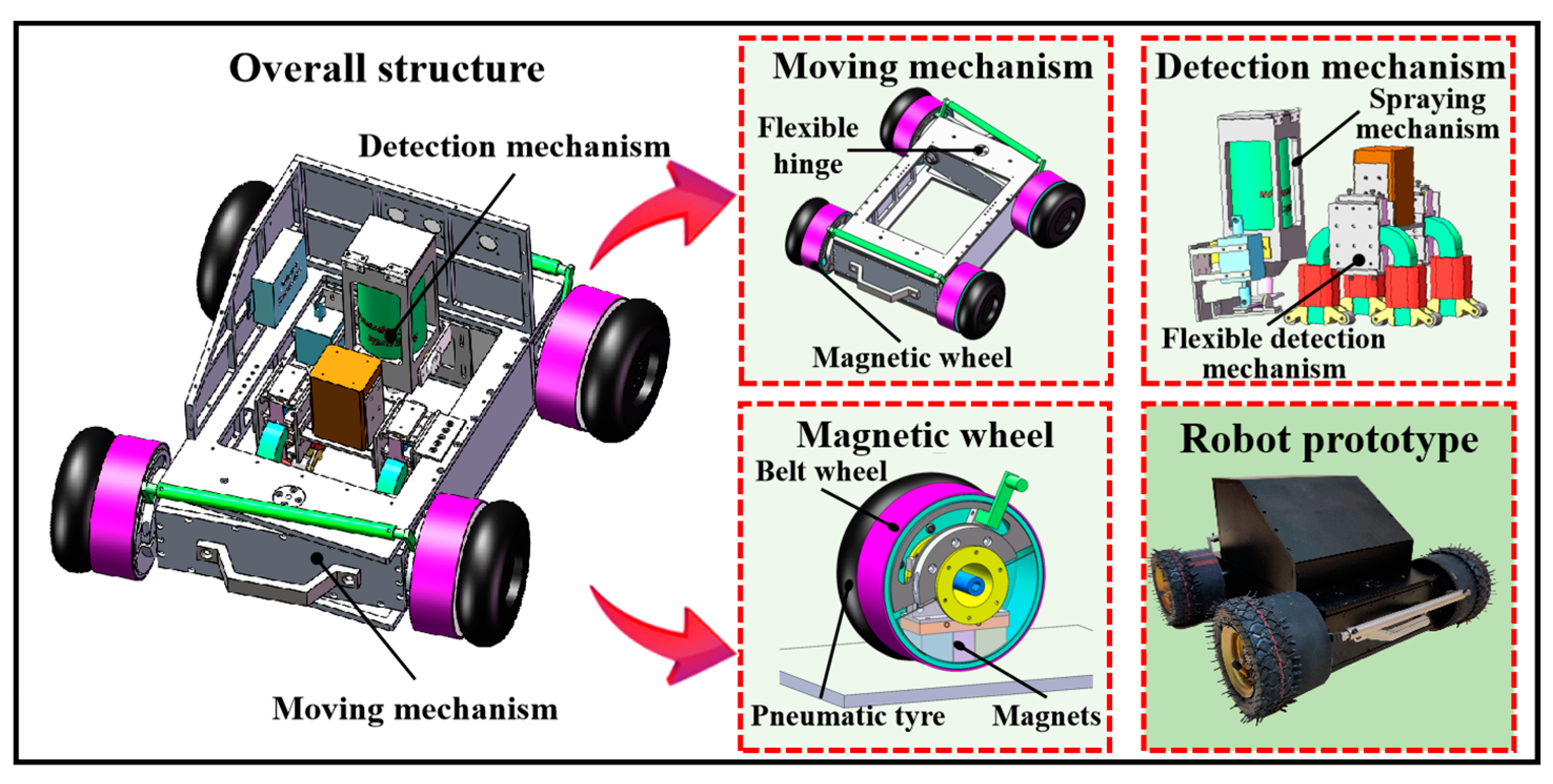
Limited by the form of moving mechanism and harsh detection process, most existing weld detection robots are difficult to meet the demand for efficient and accurate detection in shipbuilding. Therefore, there is an urgent need for a wall-climbing robot that can realize weld detection using fluorescent magnetic particle detection to improve detection efficiency and shipping safety. This paper designs a wall climbing robot that integrates stable adsorption and weld detection, solving the problems such as reliable adsorption and flexible movement of the wall climbing mechanism, dynamic and flexible adaptation of the detection mechanism, and efficient and intelligent workflow control. The overall schematic of the detection robot is shown in Figure 1.
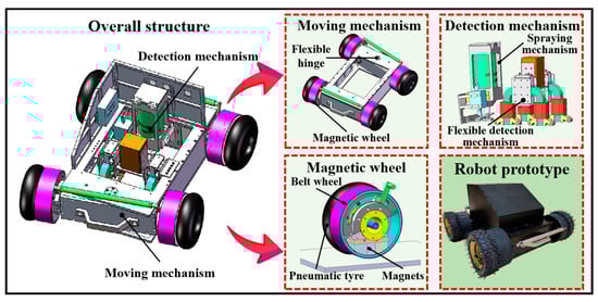
Figure 1.
Schematic diagram of the overall detection robot.
2.1. Stable and Flexible Moving Mechanism
For weld detection, the stable adsorption and flexible movement of the moving mechanism are related to detection safety and efficiency directly. We improve the multi-magnet assembling method based on the magnetic circuit conduction mechanism between multiple media, and design a non-contact, suction, adjustable lightweight permanent wheel. Inspired by the three-wheel moving mechanism, a flexible “pseudo three-wheel” wall climbing mechanism is designed by adding a flexible articulation to the traditional four-wheel mechanism, while its wheels can fit to wall tightly to provide sufficient adsorption.
2.1.1. Magnetic Wheel
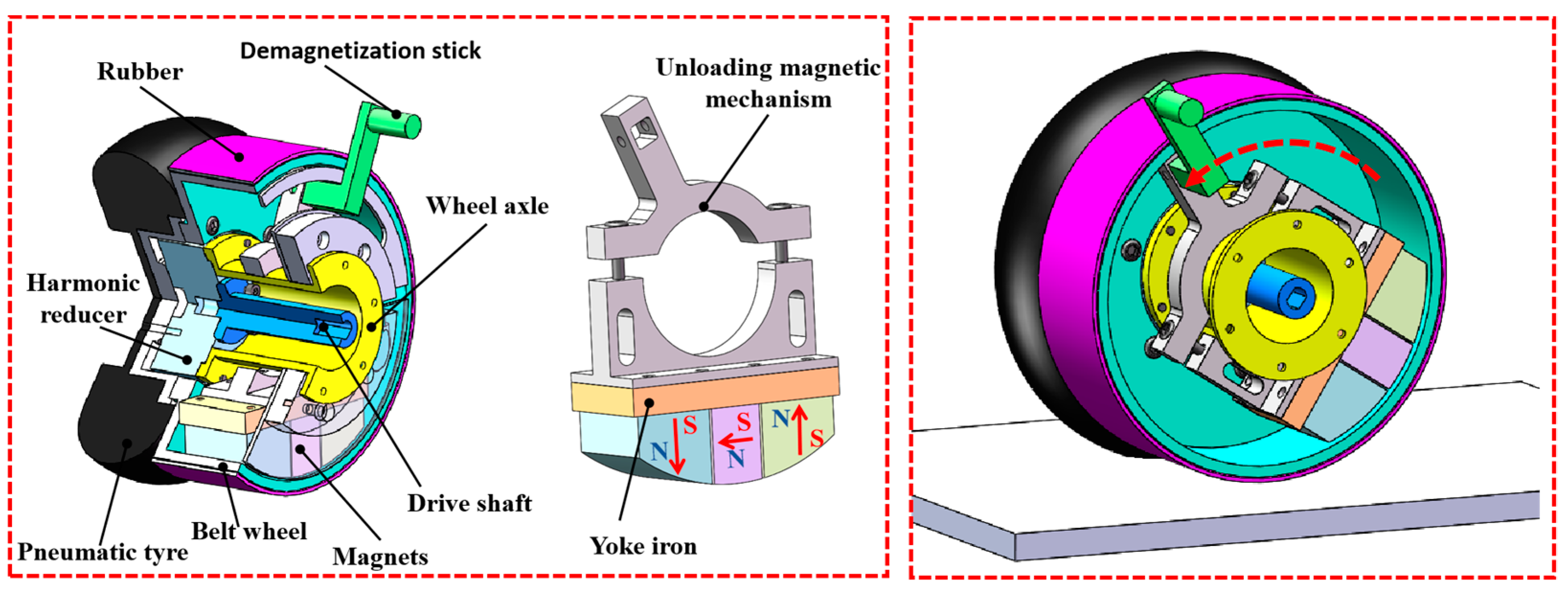
The reliable adsorption mechanism is an important condition for the safety movement on facade. Existing magnetic wheels are generally designed to place magnets to the outside of the wheel, which can contact with the wall in direct to obtain adsorption, but these wheels are easy to scratch the wall, and difficult to remove from the wall after work. Based on the analysis of the magnetic circuit conduction mechanism, an adsorption device consisting of multiple magnets is arranged inside of the wheel, thus protecting the wall. Considering that a small tangential force can rotate the magnets relatively to reduce the adsorption, a rotating magnetic unloading mechanism is designed to facilitate to remove wheel from the wall. The structure of the magnetic wheel is shown in Figure 2.
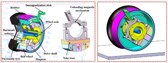
Figure 2.
The structure of the magnetic wheel.
The magnetic wheel is mainly composed of adsorption mechanism, wheel mechanism and rotating magnetic unloading mechanism. The three magnets with different magnetic poles and the yoke iron are stitched together to form a adsorption mechanism. Figure 2 shows that the magnetic poles of the magnets are arranged in a clockwise direction and fixed on the yoke iron. Using the internal conduction mechanism of each magnet, shorten the length of magnetic circuit to provide strong adsorption, while the yoke iron can also collect the surrounding magnetic energy to improve the effective utilization of the magnet. The rotating magnetic unloading mechanism is fixed with the adsorption mechanism, and hung on the wheel axle, so that it does not rotate relative to the wheel and can generate a constant adsorption. The lever principle is used to actively rotate the magnet to reduce the adsorption force, which is convenient for the magnetic wheel to remove from the wall after detection. A wheel module is fixed on the outside of the wheel axle, which can envelop the adsorption mechanism inside the wheel hub and connect with the motor output to provide power for the robot. The wheel module is composed of aluminum wheel hub and pneumatic tire to ensure the adsorption force in the appropriate range, avoid wall scratches, but also improve the friction coefficient between wall and wheels.
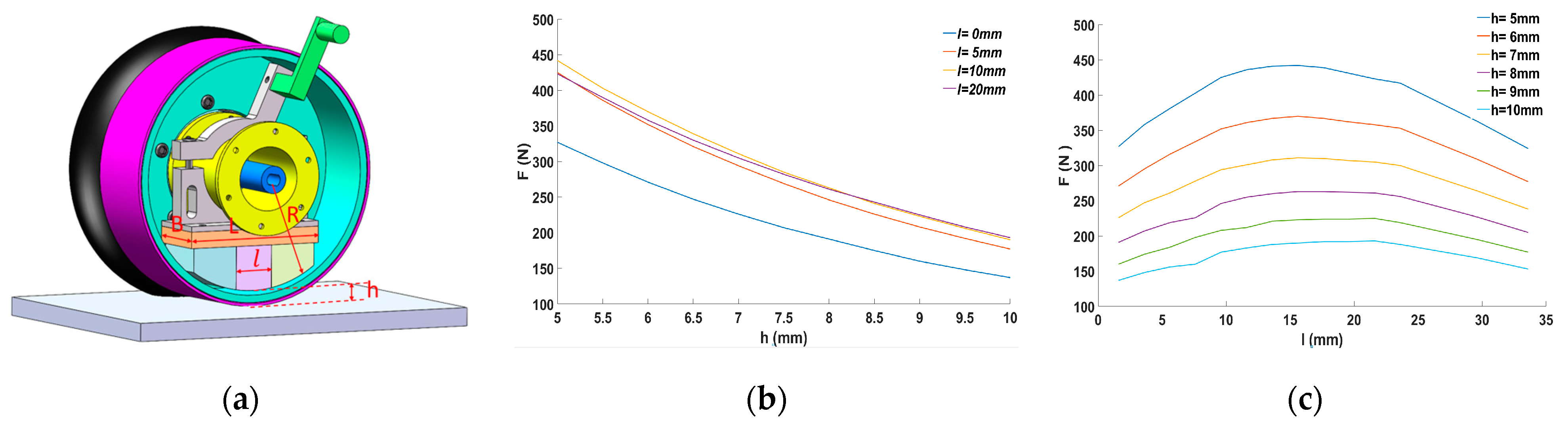
The parameters that affect the performance of the magnetic wheel are optimized to obtain the best magnetic wheel. The shape parameters of the magnet are directly related to the adsorption, and the thickness of the yoke iron is related to the amount of magnetic energy in the magnetic circuit. The width and outer diameter of the magnet and the width and thickness of the yoke iron are certainly limited by the wheel, so the length of the middle magnet is optimized. A magnetic simulation software is used to determine the variation between the magnetic wheel’s adsorption (F) and the height (h) of the wall under the influence of various parameters. The details are shown in Figure 3.
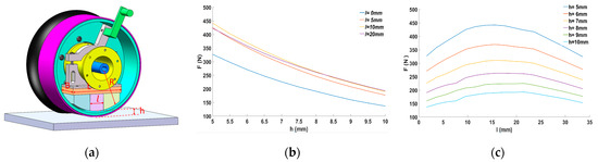
Figure 3.
Optimization of magnetic wheel parameters. (a) Schematic diagram of key structure dimensions of magnetic wheel; (b) Relationship between adsorption force of magnetic wheel and air gap; (c) The relationship between the magnetic wheel and the width of the intermediate magnet.
Figure 3b shows that the adsorption decreases (F drops from 200 N to 100 N) with increasing height (h increases from 5 mm to 10 mm) despite the different intermediate magnet length (l), which indicates that height (h) has a large effect on the adsorption (F). The reason is that the permeability of the air medium is low, which causes the loss of magnetic energy and greatly affects the adsorption; thus, the distance between the magnet and the wall must be adjusted to ensure the effective adsorption of the magnetic wheel. Figure 3c shows that intermediate magnet length (l) also directly affects the performance of the magnetic wheel. As the intermediate magnet length (l) increases from 0 mm to 30 mm, the adsorption force displays a variation of increasing and then decreasing. The role of the middle magnet is using its magnetic pole for collecting and conducting the magnetic lines generated by the main magnets on both sides to improve the magnetic field strength around the wheel. Initially, the conductivity of the adsorption mechanism gradually increases with the addition of the intermediate magnet, which also improves the adsorption force. However, with increasing its length, the magnetic conductivity becomes sat-urated relative to the two main magnets; at the same time, the two main magnets become smaller, which also reduces the magnetic performance. For this purpose, the length of the middle magnet needs to be optimized to achieve the best perfor-mance.
To obtain the best adsorption performance and determine the structural parameters, we used the software continuous nonlinear programming to analyze, carry out iterative screening, obtain optimal parameters, and completed the optimal design of magnetic wheel. The magnetic wheel adsorption experiment was conducted on an arc façade. The adsorption force was tested in horizontal, vertical and oblique states. The actual adsorption force was obtained by reading the maximum pull value in the adsorption state through the dynamometer (the pull when the wheel leaves the wall is the maximum adsorption force). Experiments show that the maximum adsorption force of the magnetic wheel is 350 N (h = 5 mm). We can also adjust the adsorption force through the height of the magnet from the wall, so that the magnetic wheel has a wide range of magnetic force variation (150–350 N), which can adapt to different requirements. The specific parameters are as follow in Table 1.

Table 1.
Magnetic wheel parameters table.
2.1.2. Moving Mechanism
The adaptability of the moving mechanism directly affects the reliable adsorption, while its movement flexibility is also related to the weld detection efficiency. When traditional moving mechanisms cross a weld with a single wheel, the other wheels cannot fit the wall tightly to provide sufficient adsorption force, which can lead to instability such as slipping and falling. Due to gravity and irregular welds, the robot needs to move flexibly to track the weld for detection. For a rigidly connected wall-climbing robot, flexible movement is difficult because it needs to overcome a large sliding friction. Therefore, a moving mechanism that can adapt to a curvature wall for flexible, stable movements needs to be designed. Based on the flexible adaptation and three-point coplanarity, the flexible hinge is integrated into the four-wheel moving mechanism, and a “pseudo tricycle mechanism” is designed to achieve curvature adaptation and stable movements. The specific structure is shown in Figure 4.
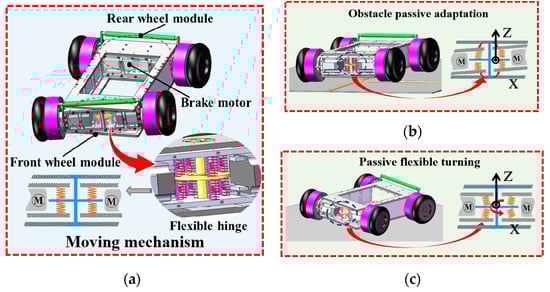
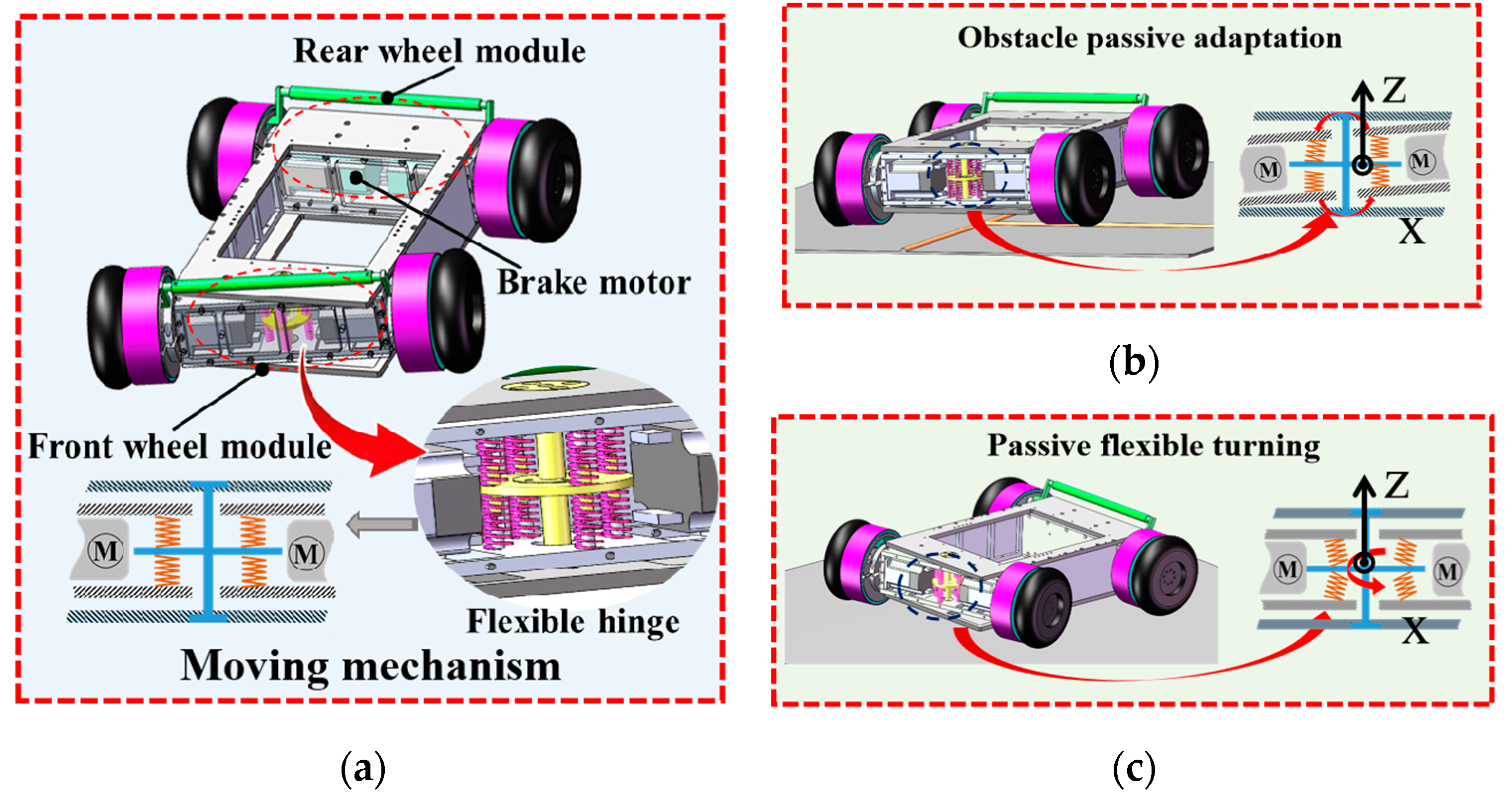
Figure 4.
Schematic diagram of flexible moving mechanism. (a) Detection robot structure diagram; (b) Passive adaptation principle of front body single wheel obstacle crossing process; (c) Passive adaptation principle of turning process.
Figure 4 shows that the moving mechanism is divided into the front and rear wheel modules, each of which can provide driving force. The rear wheel module fixed to the frame has two brake motors to prevent the robot from slipping or falling for a sudden power failure. The front wheel module is connected to the frame by a flexible hinge mechanism, which can produce some flexible deformation to adapt to obstacles and curvature changes.
The moving mechanism can be treated as a tricycle by simplifying the front wheel module to a wheel, which can adapt to a complex wall while increasing movement flexibility. The front wheel module is flexibly connected to the frame, as shown in Figure 4a. The front wheel module is constrained in the frame by two sets of parallel spring compression deformations, which form a flexible hinge mechanism, and the flexible adaptation for the wall is achieved by using the expansion, contraction deformation, and torsional deformation of the spring set. Figure 4b shows that when the wheel of the front body encounters a weld, the wheel lifts and causes the front body to rotate around the direction of the x-axis and tilt, and the upper spring of the flexible mechanism near the weld and the lower spring of the principle weld undergo compression and deformation to adapt to the existence of the weld on the wall. Due to the existence of the flexible mechanism, the front body can adapt to the wall surface by itself to avoid affecting the rear body wheel buckling, which affects the adsorption safety. Figure 4c shows that when the robot uses the differential speed on both sides for attitude adjustment, the front body and the body frame generate an angle, and each spring in the flexible mechanism twists and rotates around the Z direction, which can make the turning center of the front and rear bodies occur at the same point, improve the stability and precision of the robot movement, and reduce the turning radius to improve the flexibility of the movement. Given a variable curvature wall, the spring group in the front wheel module is disturbed by the superposition of the X and Z axes, which makes it adapt to the curvature wall.
Based on the magnetic circuit optimization method, a magnet wheel with good performance is obtained with an adsorption device assembled by multiple magnets. A rotating unmagnetized mechanism is designed by using the lever principle, which can apply a smaller force to greatly reduce the adsorption between the magnetic wheel and the wall, facilitating the robot to remove from the wall after detection. Inspired by the tricycle, the movement performance and adaptability to curvature walls is improved by incorporating a flexible hinge on moving mechanism, because flexible adaptability in multiple directions are added. Through innovative designing of the magnetic wheel and pseudo-tricycle flexible frame, a moving mechanism with stable adsorption and flexible movement is completed, which provides a guarantee for ship weld detection.
2.2. Passive-Adapted Detection Mechanism
The commonly used cross yoke with high operational efficiency is selected as the detection device for the robot to achieve fluorescent magnetic particle detection for ship welds. Restricted by the fluorescent powder detection, each leg of the cross yoke must fit the wall closely to guarantee the magnetic field strength and then display the defects clearly. However, most ships are welded with circular steels, and the existing cross yoke can hardly meet the basic requirement of closely fitting the wall when the robot moves, which affects the effectiveness and accuracy for weld detection seriously. To this end, a series-and-parallel flexible adaptation mechanism is designed for each yoke leg to fit the wall closely. Image acquisition and fluorescence magnetic suspension spraying are integrated to realize automatic weld detection and defect feature collection.
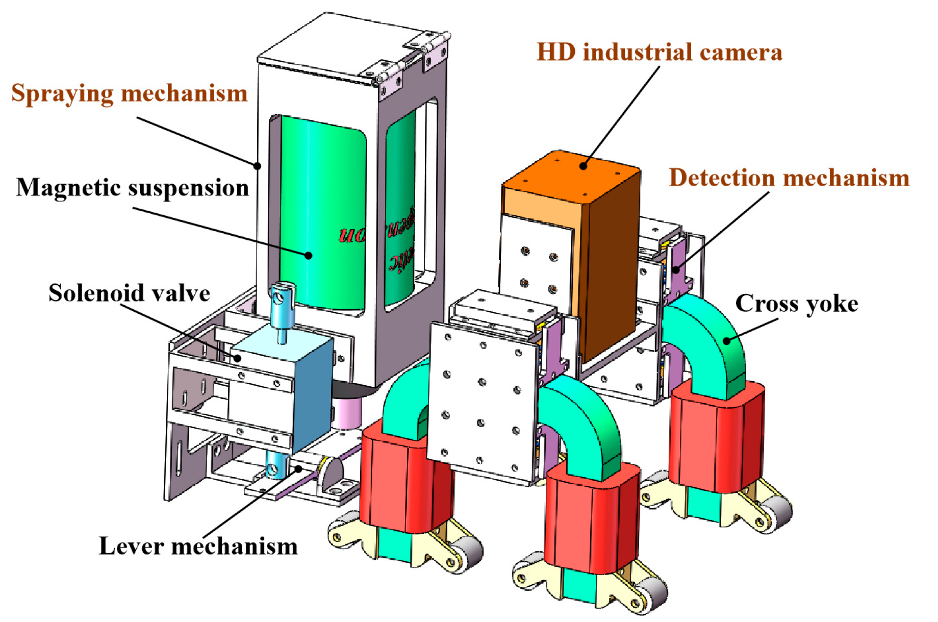
Figure 5 shows that a high-definition industrial camera is mounted above the detection mechanism to capture wall defects, and a solenoid valve is used to control the fluorescent magnetic suspension spraying. The black light is fixed on the frame, and the irradiation angle can be flexibly adjusted to cover the detection area. Thus, the fluorescent magnetic powder can be developed during the excitation, which helps the camera collect the image information of the wall features (such as slight cracks and scratches) clearly. The ability of the detection mechanism to adjust the yoke leg to achieve a tight fit with the wall passively is the key for effectiveness of the fluorescent magnetic particle detection.
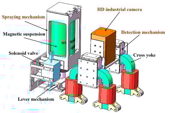
Figure 5.
Schematic diagram of detection mechanism.
The cross yoke is composed of yoke legs and two sets of series coils. The poles of each of the adjacent two legs are opposite, thus generating a toroidal magnetic field, which causes the magnetic powder inside to surge and display the defect eventually. Therefore, each yoke leg must be adjusted to fit the wall effectively to ensure that the magnetic field strength meets the detection requirements. Based on the series-and-parallel flexible adaptation structure, two sets of single yokes are designed to form a flexible detection mechanism together. The multi-DOF flexible deformation of springs is used for the flexible adaptation of the detection mechanism to the wall and a tight fit. Figure 6 shows that the yoke can be restrained by the preload force, which is generated by the compression deformation of the two sets of springs, and the flexible deformation of the spring sets provides the yoke legs a multi-DOF passive adaptation capability.
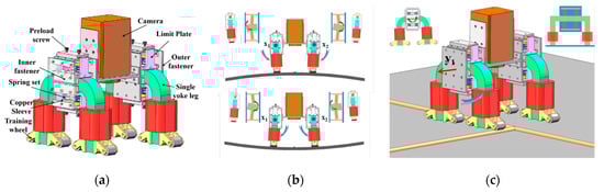
Figure 6.
Principle of flexible adaptation of detection devices. (a) Structure diagram of flexible detection mechanism; (b) Passive adaptation principle of detection mechanism in surface detection process; (c) Passive adaptation principle of detection mechanism during single wheel obstacle crossing process.
When the detection mechanism in different characteristics of the wall is used for detection operations, the yoke legs need to be adjusted according to the wall constraints, composed of series-and-parallel springs of the flexible adaptive mechanism that can be well adapted to the wall characteristics, to ensure that the yoke legs effectively fit the wall, to provide sufficient magnetic field strength to meet the needs of the detection. Figure 6b shows that when the detection area is a circular outer wall, the spring set produces a bending deformation to make the yoke legs produce an angle to fit the circular surface: The single yoke leg 1 is passively rotated counterclockwise around the x1-axis, and the single yoke leg 2 is passively rotated clockwise around the x2-axis, so that the cross yokes can closely fit the wall to maintain sufficient magnetic field strength. Figure 6c shows that when a cross weld is encountered, the yoke leg rotates counterclockwise along its y1-axis to cross the weld and to keep the yoke close to the detection area because the two sets of springs are deformed by different degrees of compression.
A wheeled wall-climbing mechanism with stable adsorption and flexible movement capability is innovated based on magnetic circuit optimization and fusion hinge mechanism. A series-and-parallel flexible adaptation detection mechanism with multi-DOF flexible adaptation is designed to fit the wall tightly to meet the excitation detection requirements. Moreover, image acquisition and automatic spraying mechanism and other auxiliary institutions are integrated to meet the magnetic particle detection and achieve the automatic, accurate, and efficient weld detection on ships.
3. Robot Mechanics Analysis
The robot weight and the adsorption force directly affect the safety and efficiency detection during work on ships. Realizing the adaptation between the adsorption and weight and solving the contradiction between safe adsorption and flexible movement is a difficult problem. A variable, the robot posture angle, is introduced, and a unified systematic analysis is performed by varying the parameter values to find the optimal adsorption force. The influence of the angle between the front wheel and the frame on the movement flexibility is analyzed, and the flexible movement control on the facade is realized by establishing a dynamic model. Through the analysis of mechanical model on ships, the robot can achieve safe adsorption and flexible movement.
The mechanical model of the robot on the space elevation is shown in Figure 7, which is mainly gravity, magnetic wheel adhesion force and wall support force, and friction force. The direction of gravity is constant downward, the wall support force and the magnetic wheel adsorption force are perpendicular to the wall, and the friction force is parallel to the robot’s forward direction.
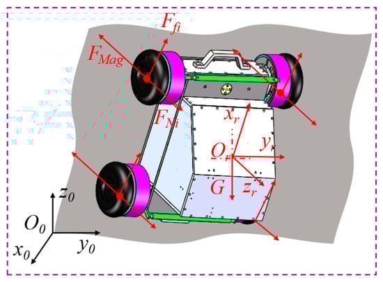
Figure 7.
Force analysis of robot in space facade.
The mechanical model of the robot on the space elevation is shown in Figure 7, which is mainly gravity, magnetic wheel adhesion force, and wall support force, and friction force. The direction of gravity is constant downward, the wall support force and the magnetic wheel adsorption force are perpendicular to the wall, and the friction force is parallel to the robot’s forward direction.
3.1. Static Analysis
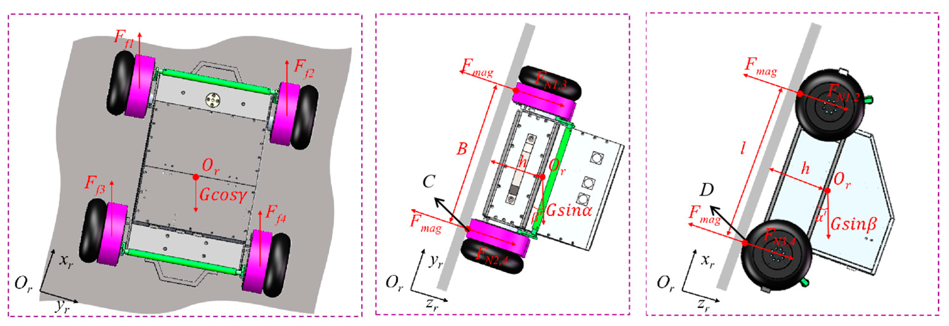
During climbing on facade for wall-climbing robots, if the adsorption is insufficient, instability may occur such as falling, slipping, tipping and overturning. To achieve safe adsorption and stable movement, we perform mechanics analysis for each instability case to obtain the minimum adsorption force. The mechanical model is shown in the Figure 8.
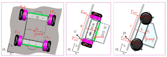
Figure 8.
Mechanical model of robot in space facade.
Each magnetic wheel can achieve the maximum adsorption force that meets the tight wall (each wheel can provide stable adsorption force). The angle of gravity under the robot body coordinate system is . s is the safety factor, which compensates for the adverse effects of cables and harsh environment on the robot. Other parameters are described in Table 2.
Table 2.
Annotation of the Symbols in the diagram.
To ensure that that the robot can adsorb on walls safely and stably and to avoid falling due to gravity, the balance equation is established along the robot’s z-axis direction.
The constraint, , is satisfied for the robot to adsorb stably on the facade without dropping, and thus the adsorption force of the magnetic wheel can be found as follows.
An equation of robot balance is established on the robot plane, to ensure that the robot can adsorb stably on facade without slipping.
The constraint, , is satisfied to adsorb stably without slipping, and the wheel adsorption force can be found as follows.
The mechanical model is simplified under space to the corresponding 2D plane for separate analysis to analyze the rollover and overturning easily and intuitively. The mechanical model is projected onto the plane to analyze the situation when the robot rolls over, which requires moment balance equation with point C as the center of rotation, as shown below.
where, is the angle between G and the Y-axis in the plane.
The constraint, , is satisfied to adsorb stably without rolling, and thus the wheel adsorption force can be found as follows.
Similarly, we analyze the case of robot tipping in the plane, which requires the moment balance equation with point D as the center of rotation, as shown below.
where, is the angle between G and the X-axis on the plane.
The constraint, , is satisfied to adsorb stably without tipping, and thus the wheel adsorption force can be found as follows.
Combining the mechanics analysis of the above four instability cases, the minimum adsorption force of the magnetic wheel can be obtained as:
By establishing robot mechanics model for different conditions and analyzing various instability states, we can obtain the minimum adsorption force for stable movement on facade. The lightweight design is also carried out to complete the optimization. The main parameters of the final obtained wall climbing detection robot are shown as follows.
The mechanical model is simplified under space to the corresponding 2D plane for separate analysis to analyze rollover and overturning easily and intuitively. The mechanical model is projected onto the plane to analyze the situation when the robot rolls over, which requires moment balance equation with point C as the center of rotation, as shown in Table 3.
Table 3.
Detection robot parameters table.
3.2. Kinematic Analysis
In targeting weld detection for ships, deviations in movement trajectory relative to the weld may be observed due to irregular obstacles, gravity, or deviations in the weld. The robot needs to adjust its attitude through flexible movement to achieve accurate tracking of the weld and detection efficiency. The moving mechanism incorporates a flexible hinge mechanism to obtain a smaller turning radius by actively adjusting the angle between the front wheel module and the body frame and complete a fast, flexible adjustment so that the robot can actively track the weld and achieve effective detection.
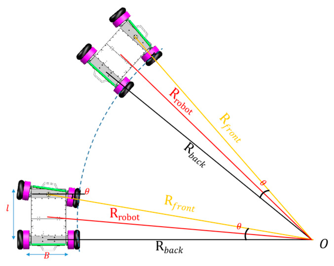
Figure 9 shows the robot climbing vertically on a wall; θ is the angle between the front wheel module and the body frame, which is achieved by actively adjusting the motor speed and direction; and the range of θ is (−30°, 30°) due to the structural limitation. Because θ exists, the turning radii of the front and rear wheel modules are different, so the turning radius of the center point P is taken as the overall turning radius. The movement model is built as shown below.

Figure 9.
Turning process on facade.
The relationship between the turning radius of the front and rear wheel modules can be obtained from the robot structural dimensions as follows.
The relationship between the turning radius and each wheel speed for the existence of the angle θ can be obtained as follows:
3.3. Dynamical Analysis
After completing the structural optimization and solving the safety and stability adsorption, the dynamics to realize flexible movement control must be analyzed.
The vertical upward movement, the most severe force condition, is selected for mechanical modeling and analysis to establish the dynamic model, as shown in Figure 10.
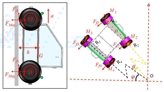
Figure 10.
Dynamics analysis of robot.
According to the force balance and Newton’s second law, the dynamic model of vertical upward movement can be obtained as follows:
By solving the above model, the minimum torque required for the motor can be obtained as follows:
To analyze the robot’s mechanical model in the turning state on the facade, θ is introduced again to establish the moment balance equation with O as the center of rotation.
where is the torque provided by wheel ; is the frictional force applied to wheel ; is the turning radius corresponding to wheel during turning; are the body weights shared by the front and back wheel modules, respectively; and is the angle turned by the robot. Assuming that the front and back wheel modules share half of the weight, while the frictional forces applied to each wheel are equal, the following simplification is made for the convenience of calculation.
The following equation can be derived by jointly calculating Equations (15)–(17):
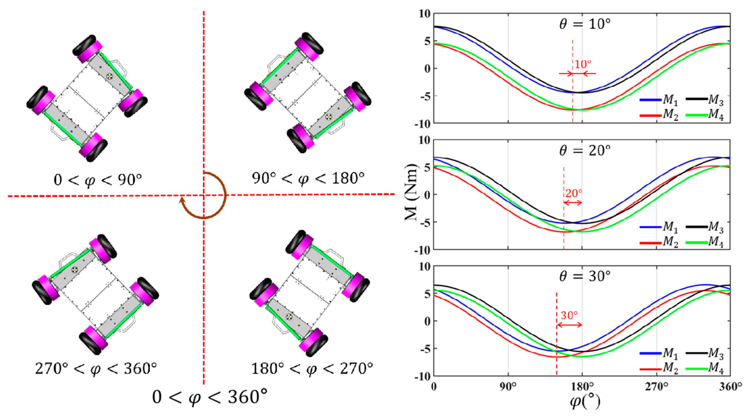
The motor’s torque for the turning state can be calculated by changing the angle (). Figure 11 shows the curve of the required torque with angle for different θ angle.
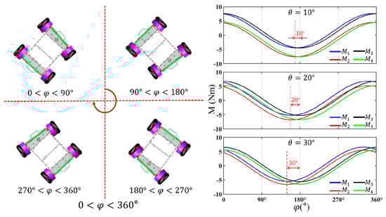
Figure 11.
The torque changes required by each motor during turning process.
Figure 11 shows that the larger the angle θ is, the smaller the turning radius is. With the increase in θ, the difference between the two wheels’ required torque in the wheel module () is greater, but the torques during the turning is similar (), which is only due to the existence of an output phase difference θ. In completing one circle of movement with the same θ, the robot requires the largest torque in the vertical upward state (around ) because gravity is an unfavorable factor that needs to be overcome. Moreover, the motor output torque is negative at , which indicates that gravity plays the main driving role, while the motor generates the braking torque. Through the above analysis, the motor torque can be distributed to improve the robot’s flexible, supple movement and to reduce the energy loss.
Several common instability states have been analyzed by building a static model with positional parameters, and the optimal range of the magnetic wheel is obtained to achieve stable adsorption of the wall-climbing robot. Combining the structural features, a simple kinematic model is established, and the relationship between the wheel speeds and the turning radius is obtained; thus, the fast pursuit of the weld can be realized by actively adjusting the wheel speed. Climbing movement and turning on the facade is analyzed, and the optimal driving torque is obtained, which can realize the flexible, smooth movement.
4. Control System
The stability and reliability of the control system is important for the robot to ensure efficient, automatic detection. Affected by complex detection, the robot needs to realize the collaborative operation of multiple components through remote operation, such as precise movement, excitation detection, magnetic suspension spraying, and image acquisition. The robot also needs to meet the real-time and accuracy requirements. A set of automatic workflows consistent with the standard detection is developed by combining standard detection workflow with the structural characteristics of each component. On this basis, a set of control system using IPC as the main control unit and fusing multisensor information for multicomponent collaboration is established, which can realize the efficient, precise detection on ships.
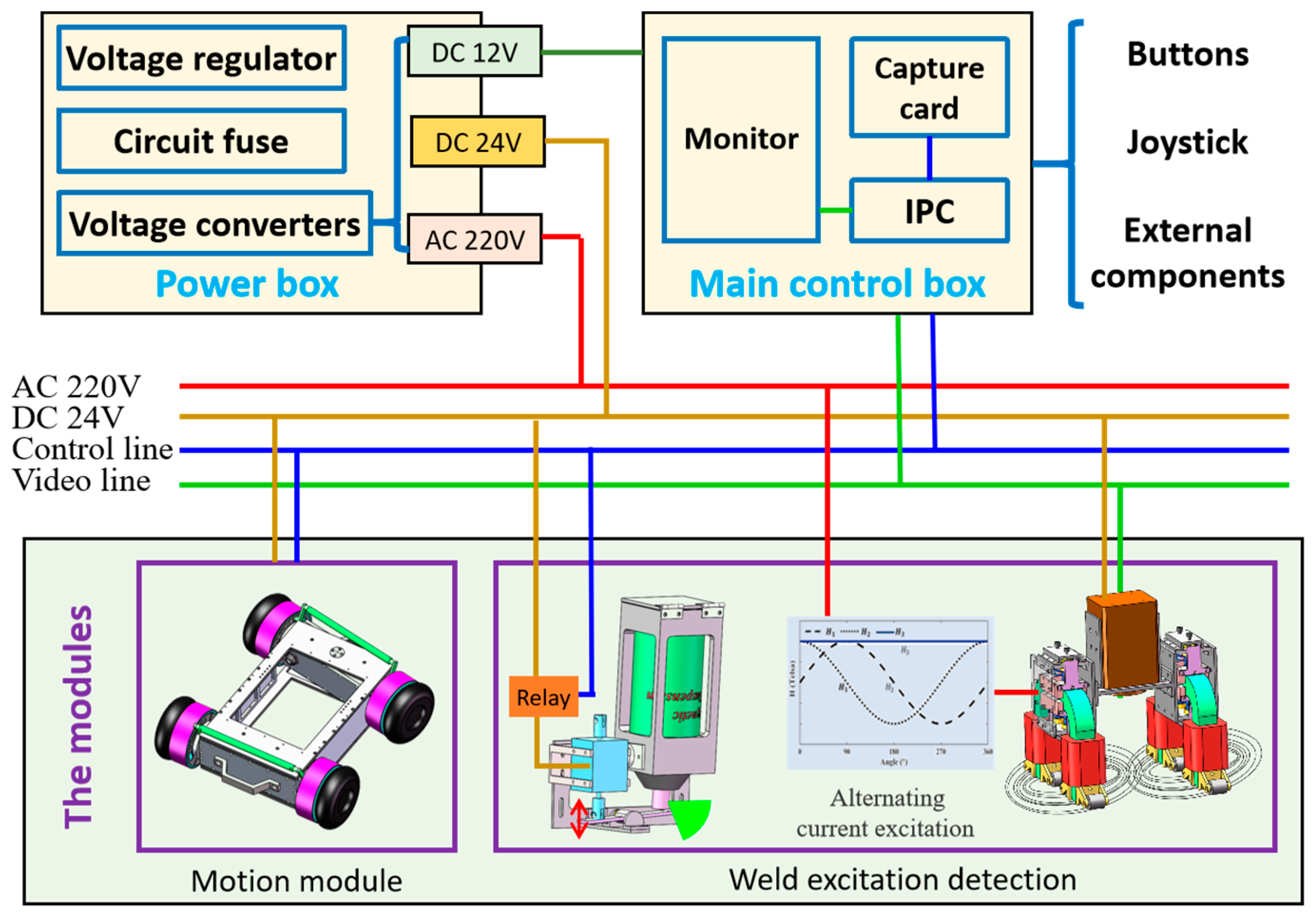
The hardware integration of the control system and the high-precision cooperation between the components are the prerequisites for detection robot to achieve automatic detection. The IPC is set as the main control unit to plan and control the detection, and the communication bus is used to communicate and control the robot movement, magnetic field control and excitation detection, magnetic suspension spraying, image acquisition, and other modules to complete the weld detection. The control system composition is shown in Figure 12.
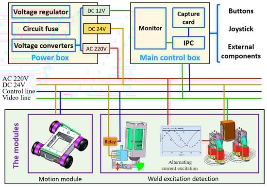
Figure 12.
The control system composition of the detection robot.
After the external AC power supply is processed by circuit protection, voltage stabilization, and filtering modules, it is transformed to obtain various DC power required while avoiding safety hazards. The monitor in the control box can display the image information through the cable while using external components such as button rockers for human–robot interaction to achieve efficient detection. The motors are synchronized in real time to realize the precise movement, and the movement of each motor obtained by using the self-contained encoder can be used for feedback control. The automatic spraying of the magnetic suspension is performed by controlling the solenoid valve in the module and using its lever structure principle to press the nozzle to complete spraying. The on/off state of the cross yoke is managed to control the magnetic field so that it meets the strength requirements for fluorescent magnetic particle detection. During the detection, a high-definition industrial camera is used to collect weld images and transmit the video to the monitor through a network transmitter. The images are captured and saved to a control box, which facilitates information retrieval and digital cycle management. Distributed bus architecture is built to realize real-time, accurate cooperation of multiple modules and lines to complete efficient automatic weld detection.
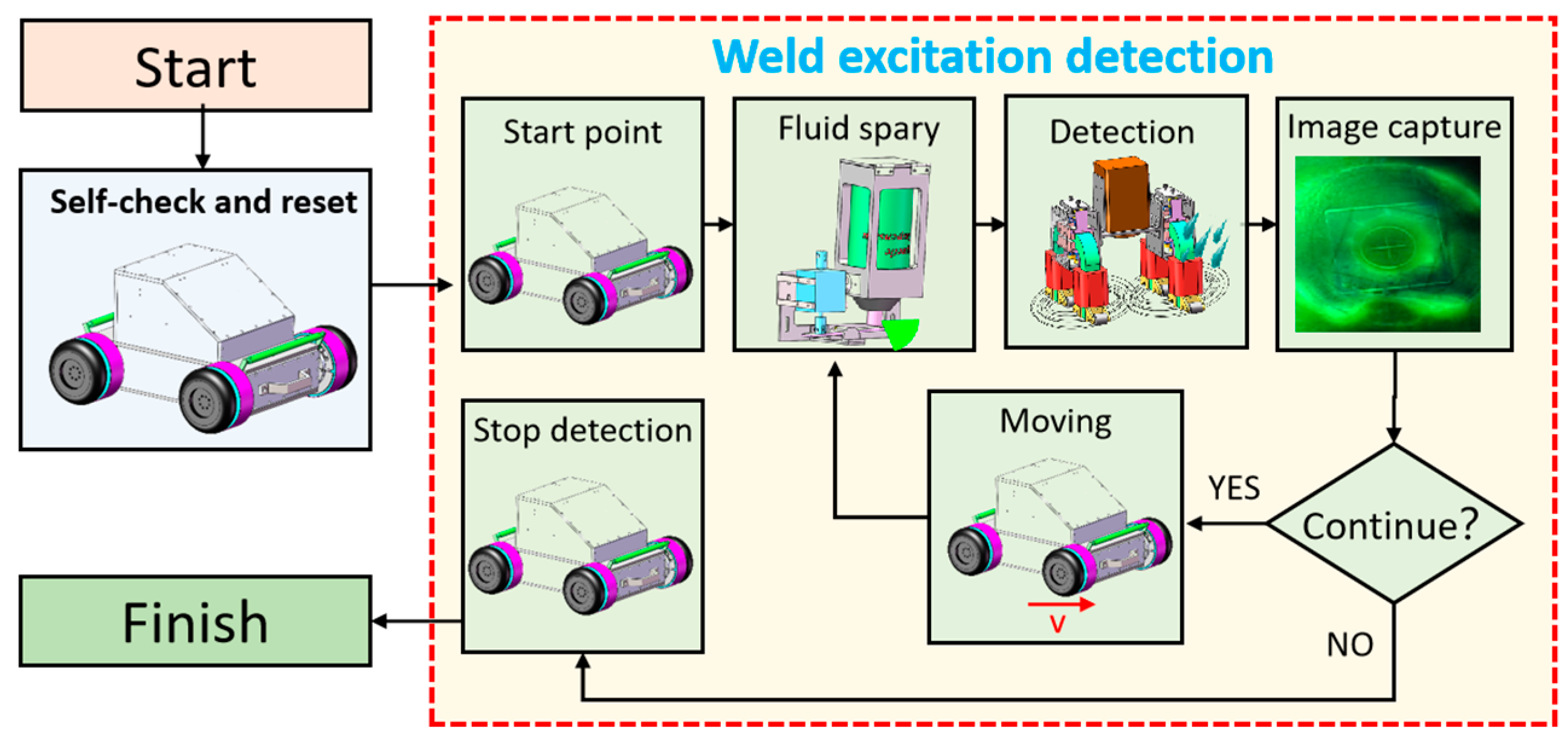
Human-like flexible work and standard-compliant detection processes are important factors that drive efficient, accurate detection. A multimodule collaborative detection is developed by incorporating the fluorescent magnetic particle weld detection and robot structural characteristics to realize weld automatic detection. The specific detection is shown in Figure 13.
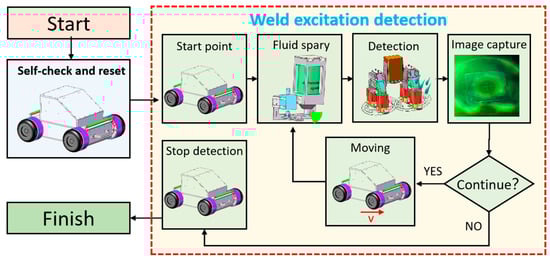
Figure 13.
The workflow of the detection robot.
1. Power on, open the control software, complete the self-test, and reset.
2. Control the motors to move the robot to the initial detection position.
3. Energize the solenoid valve to press the nozzle, which can realize the magnetic suspension spraying.
4. Control cross yoke excitation detection, and magnetize the wall to force the magnetic powder to surge, which can display the defect.
5. Disconnect the power of the solenoid valve, and stop spraying the magnetic suspension after 2 s of excitation.
6. Turn on the black light, control the camera to capture the current image, and transfer the image to control box.
7. Disconnect the power to the cross yoke, and stop the excitation detection after image acquisition.
8. Control the robot to move to the next detection position, and start the cycle of automatic detection.
When the robot detects an abort signal, the robot stops the cycle after completing the current automatic detection and then resets.
The design of the automatic detection with multicomponent cooperative control is realized by analyzing the fluorescent magnetic particle detection technology and the characteristics of the robot modules. An industrial computer is used as the main unit to plan and control the detection, and a communication bus is used to communicate with each functional module remotely and separately to realize high-precision cooperative operation and complete the automatic weld detection.
5. Experiments
An automatic magnetic particle detection robot is developed to realize automatic weld detection for ships. The system mainly consists of detection robot, control box, power supply box, and cables. The detection robot, equipped with a flexible detection mechanism on the magnetic adsorption moving mechanism, is used to achieve stable movement and accurate detection on ships. The control box integrated with the hardware system is mainly used to manipulate the detection remotely through human–computer interaction. The power box is used to provide various stable, safe voltages for the robot. Movement and detection operation experiments are conducted on a circular wall with a thickness of 10 mm and a diameter of 8 m, as shown in Figure 14.
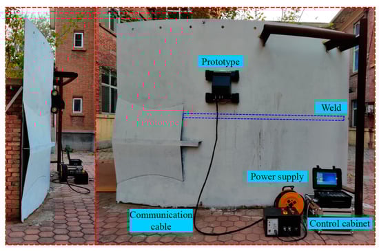
Figure 14.
The experimental environment of the detection robot.
5.1. Movement Experiments
The stable, precise movement on a facade is the prerequisite to ensure safe, efficient detection. The horizontal climbing, vertical climbing, and turning movement experiments are designed to test the robot’s stable adsorption and precise movement ability. The robot movement performance is analyzed by observing the movement state and collecting each motor encoder and inertial navigation information.
Figure 15 shows horizontal wall climbing, vertical climbing, and elevation turning movement tests conducted on a facade. The robot could complete the movement stably, and no instability is observed, which indicates that the robot has satisfactory adsorption performance. Moreover, the robot can still move according to the predetermined path and meet the requirements of accurate movement despite slight fluctuations based on observations and comparison of the actual forward heading angle of the robot with the ideal state.
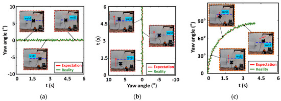
Figure 15.
The elevation movement experiments of the detection robot. (a) Robot horizontal crawling experiment; (b) Robot crawling upright experiment; (c) Robot turning experiment.
During horizontal crawling on the simulated workpiece, the curve of the robot mass center in the horizontal direction over time is shown in Figure 15a. During the horizontal crawling at a speed of 0.15 m/s, the robot slips under the influence of gravity, and the amount of sliding is 3 mm. The calculated sliding rate is 0.003 (3 mm/0.9 m), which is small and can meet the testing requirements. During vertical crawling, the curve of the robot mass center in the vertical direction over time is shown in Figure 15b. The robot climbs upward at 0.15 m/s, and the robot center of mass offset is not offset. Figure 15c shows the curve of robot inclination over time and the robot trajectory on the workpiece during the robot’s turn from vertical to horizontal. Because of the flexible hinge, the angle between the front module and the body changes, and then different speeds are set to realize the robot turning, which greatly reduces the turning radius of the robot (R = 4 m) and improves the flexibility of movement.
The experiments show that the robot can achieve horizontal crawling, vertical crawling, and turning movement on a wall in a stable manner. The robot can weld across without instability, and its movement is flexible and accurate.
5.2. Detection Performance Experiments
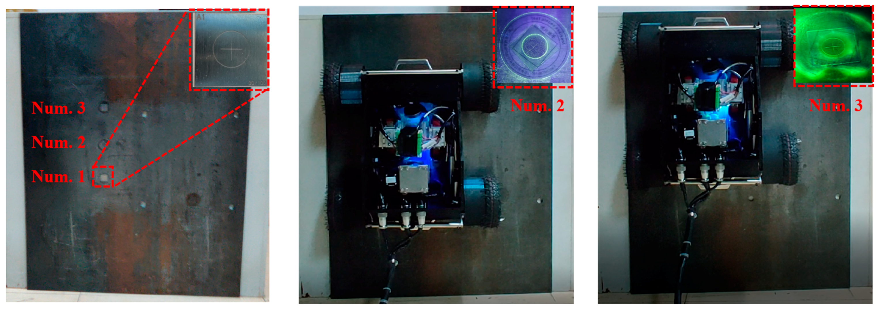
To test the detection accuracy, three standard specimens of medium sensitivity (30/100) are pasted on a 5 mm thick vertical steel plate, as shown in Figure 16. After the robot adjusts its posture, it performs automatic detection with the standard technology through the synergistic cooperation among the various components such as spraying magnetic suspension, excitation detection, image acquisition, and robot movement.
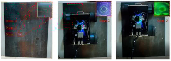
Figure 16.
The detection experiments of the standard specimen.
Figure 16 shows that the robot can complete the detection, which can show the defects in the specimen by cross-excitation to make the magnetic powder in the magnetic suspension surge. The industrial camera can clearly pick up defects. The experiments confirm that the robot can realize the standardized detection and has satisfactory detection capability and high detection accuracy (can detect defects as deep as 30 μm). Subsequently, the weld in the simulated workpiece is examined, as shown in Figure 17. The acquired images confirm that the wall information in the inspection area can be seen with no defects.
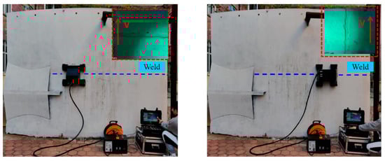
Figure 17.
The weld detection test on simulated tanks.
The experiments show that the detection robot has satisfactory adsorption capability and can move stably and flexibly on facade, while the detection mechanism can passively adapt to the wall to provide the magnetic field strength required to excitation detection. The robot can complete the detection through the collaborative control of multiple components incorporating standard detection, and the tests using medium-sensitivity specimens confirm that the detection accuracy is also sufficient to meet the requirements. Overall, the developed detection robot can achieve efficient, accurate weld detection using fluorescent magnetic particle, which can replace manual labor to achieve intelligent detection.
6. Discussion
Different from the traditional monolithic magnet adsorption mechanism, an assembled magnet adsorption mechanism is designed based on the optimization of magnetic circuit. By integrating the flexible hinge mechanism, a pseudo tricycle moving mechanism with wall adaptability is proposed, which solves the problem of stable adsorption and flexible movement for a wall-climbing robot on facade.
Compared with the rigid connected detection mechanism, a flexible detection mechanism with a series-and-parallel flexible adaptation structure is designed to solve passive adaptation of the detection probe to circular walls by using its multi-DOF deformation, improving the detection accuracy and efficiency.
A unified mechanical modeling method is proposed for different working conditions on a facade, and the force state at each position in space can be expressed by the robot attitude angle. Kinematic and dynamic analyses are conducted to solve the technical contradiction between stable adsorption and flexible movement.
By integrating the standard fluorescent powder weld detection and robot structure characteristics, an automatic fluorescent powder detection workflow based on multicomponent cooperative control is proposed. The robot completes the fluorescent magnetic particle detection using cables to achieve information transmission and process control.
The experimental results show that the developed detection robot can move safely and stably on circular walls, and its flexible detection mechanism can passively adapt to the wall for accurate detection. With the established detection workflow, the detection robot can perform efficient, autonomous excitation detection, while the weld defect information can be accurately and clearly observed and saved.
7. Conclusions
Based on flexible motion and efficient detection, an automatic magnetic particle detection robot is designed for weld detection in ship manufacturing. Considering that gravity varies with the moving direction, a uniform mechanical model is constructed to describe the mechanical state of the robot accurately. Based on the analysis of the corresponding cooperative relationship between the detection and the mechanism components, a set of automatic detection operation control process is established. Finally, the robot can complete nondestructive weld detection on a ship.
Combined with the development of detection robots and experimental testing, the existing robots can complete automated weld detection. However, a few problems remain.
The detection robot now relies on the fluorescent agent in the bottle to spray fluorescent magnetic powder on the wall surface. Considering the volume of the bottle, limitations are imposed on the robot’s operating time and area. In a later stage, the design of a quick-change device to replace the fluorescent agent in the bottle conveniently and swiftly will be considered.
The overall weight of the robot is substantial now, and optimizing the light weight of the robot at a later stage while meeting the structural strength and rigidity can be considered
The detection robot now relies on the fluorescent agent in the bottle to spray fluorescent magnetic powder on the wall surface. Considering the volume of the bottle, there are limitations on the robot’s operating time and area, and in the later stage, we will consider the design of a quick-change device to replace the fluorescent agent in the bottle in a convenient and quick manner;
The overall weight of the robot is heavy now, and we can consider optimizing the light weight of the robot at a later stage while meeting the structural strength and rigidity.
Author Contributions
X.Z.: Methodology, Software, Validation, Investigation, Data curation, Writing—review and editing. M.Z.: Methodology, Investigation, Formal analysis, Software, Visualization, Writing—original draft, Writing—review and editing. S.J.: Methodology, Validation, Resources, Supervision, Project administration, Writing—review and editing. L.S.: Software, Visualization, and Supervision. M.L.: Visualization, and Supervision. All authors have read and agreed to the published version of the manuscript.
Funding
This research is supported by National Natural Science Foundation of China (grant numbers: U1913211, 52275016, and 52275017), the Science and technology development fund project on central government guiding local government (grant number: 226Z1801G and 226Z1811G), the Natural Science Foundation of Hebei Province (grant number: F2021202016, F2021202062 and E2022202130) and State Key Laboratory of Reliability and Intelligence of Electrical Equipment (grant number: EERI_OY2021004).
Data Availability Statement
The data presented in this study is available in the article.
Conflicts of Interest
The authors declare that they have no known competing financial interests or personal relationships that could have appeared to influence the work reported in this paper.
References
- Amiri, N.; Farrahi, G.-H.; Kashyzadeh, K.-R.; Chizari, M. Applications of ultrasonic testing and machine learning methods to predict the static & fatigue behavior of spot-welded joints. J. Manuf. Process. 2020, 52, 26–34. [Google Scholar]
- Hou, W.; Zhang, D.; Wei, Y.; Guo, J.; Zhang, X. Review on Computer Aided Weld Defect Detection from Radiography Images. Appl. Sci. 2020, 10, 1878. [Google Scholar] [CrossRef]
- Hsu, Q.-C.; Ni, R.-H.; Ye, J.-H.; Ngo, N.-V. Automatic Optical Inspection for Magnetic Particle Detection of Forging Defects. In Proceedings of the 2019 ICERA International Conference on Engineering Research and Applications, Thai Nguyen, Vietnam, 1–2 December 2019; pp. 144–154. [Google Scholar]
- Wright, M. Nondestructive Testing Methods. Encycl. Marit. Offshore Eng. 2017, 565, 1–13. [Google Scholar]
- Bonnin-Pascual, F.; Ortiz, A. On the use of robots and vision technologies for the inspection of vessels: A survey on recent advances. Ocean Eng. 2019, 190, 106420. [Google Scholar] [CrossRef]
- Sattar, T.; Corsar, M.; James, R.; Seghier, D. Robotics Transforming the Future-Proceedings of the 21st International Conference on Climbing and Walking Robots and the Support Technologies for Mobile Machines. CLAWAR 2018, 171, 183. [Google Scholar]
- Li, X.; Jiang, H.; Yin, H. Detection of surface crack defects on ferrite magnetic tile. NDTE Int. 2014, 62, 6–13. [Google Scholar] [CrossRef]
- Fan, K.-C.; Chen, S.-H.; Chen, J.-Y.; Liao, W.-B. Development of auto defect classification system on porosity powder metallurgy products. NDTE Int. 2010, 43, 451–460. [Google Scholar] [CrossRef]
- Zolfaghari, A.; Kolahan, F. Reliability and sensitivity of magnetic particle nondestructive testing in detecting the surface cracks of welded components. Nondestruct. Test. Eval. 2018, 33, 290–300. [Google Scholar] [CrossRef]
- Liu, J.; Xu, L.; Xu, J.; Liu, L. Analysis and optimization of the wall-climbing robot with an adsorption system and adhesive belts. Int. J. Adv. Robot. Syst. 2020, 17, 1729881420926409. [Google Scholar] [CrossRef]
- Liu, J.; Xu, L.; Xu, J.; Li, T.; Chen, S.; Ceccarelli, M. Design, Modeling and Experimentation of a Biomimetic Wall-climbing Robot for Multiple Surfaces. J. Bionic Eng. 2020, 17, 523–538. [Google Scholar] [CrossRef]
- Zhou, Q.; Li, X. Experimental investigation on climbing robot using rotation-flow adsorption unit. Robot. Auton. Syst. 2018, 105, 112–120. [Google Scholar] [CrossRef]
- Ishihara, H. Basic study on wall climbing root with magnetic passive wheels. In Proceedings of the 2017 IEEE International Conference on Mechatronics and Automation (ICMA), Takamatsu, Japan, 6–9 August 2017; pp. 1964–1969. [Google Scholar]
- Yan, C.; Sun, Z.; Zhang, W.; Chen, Q. Design of novel multidirectional magnetized permanent magnetic adsorption device for wall-climbing robots. Int. J. Precis. Eng. Manuf. 2016, 17, 871–878. [Google Scholar] [CrossRef]
- Fan, J.; Xu, T.; Fang, Q.; Zhao, J.; Zhu, Y. A Novel Style Design of a Permanent-Magnetic Adsorption Mechanism for a Wall-Climbing Robot. J. Mech. Robot. Trans. Asme 2020, 12, 035001. [Google Scholar] [CrossRef]
- Chen, X.; Wu, Y.; Hao, H.; Shi, H.; Huang, H. Tracked Wall-Climbing Robot for Calibration of Large Vertical Metal Tanks. Appl. Sci. 2019, 9, 2671. [Google Scholar] [CrossRef]
- Huang, H.; Li, D.; Xue, Z.; Chen, X.; Liu, S. Design and performance analysis of a tracked wall-climbing robot for ship inspection in shipbuilding. Ocean. Eng. 2017, 131, 224–230. [Google Scholar] [CrossRef]
- Gao, F.; Fan, J.; Zhang, L.; Jiang, J.; He, S. Magnetic crawler climbing detection robot basing on metal magnetic memory testing technology. Robot. Auton. Syst. 2020, 125, 103439. [Google Scholar] [CrossRef]
- Lee, G.; Kim, H.; Seo, K.; Kim, J.; Sitti, M. Series of Multilinked Caterpillar Track-type Climbing Robots. J. Field Robot. 2014, 33, 737–750. [Google Scholar] [CrossRef]
- Wang, Z.; Zhang, K.; Chen, Y.; Luo, Z.; Zheng, J. A real-time weld line detection for derusting wall-climbing robot using dual cameras. J. Manuf. Process. 2017, 27, 76–86. [Google Scholar] [CrossRef]
- Munasypov, R.-A.; Shakhmamet, T.-R.; Moskvichev, S.-S.; Sletnev, P.-V.; Meshkov, I.-V. High mobility robotic platform for the tasks of diagnosing elements of ship structures. In Proceedings of the International Conference on Extreme Robotics, Hong Kong, China, 24–26 June 2016. [Google Scholar]
- Wang, R.; Kawamura, Y. Development of climbing robot for steel bridge inspection. Ind. Robot Int. J. 2016, 43, 429–447. [Google Scholar] [CrossRef]
- Tang, F.-D.; Yu, Y.-F. Nondestructive testing method for welding quality in key parts of oceangoing ships. J. Coast. Res. 2020, 110, 91–94. [Google Scholar] [CrossRef]
- Kolokolnikov, S.; Dubov, A.; Medvedev, A.; Boriskin, D. Comprehensive inspection of refrigerated ammonia storage tank welded joints by the metal magnetic memory technique and conventional NDT methods. Weld. World 2020, 64, 1659–1670. [Google Scholar] [CrossRef]
- Zhang, Z.; Yang, Z.; Ren, W.; Wen, G. Random forest-based real-time defect detection of Al alloy in robotic arc welding using optical spectrum. J. Manuf. Process. 2019, 42, 51–59. [Google Scholar] [CrossRef]
- Milella, A.; Maglietta, R.; Caccia, M.; Bruzzone, G. Robotic inspection of ship hull surfaces using a magnetic crawler and a monocular camera. Sens. Rev. 2017, 37, 425–435. [Google Scholar] [CrossRef]
- Jung, M.; Park, B.; Bae, J.; Shin, S. PAUT-based defect detection method for submarine pressure hulls. Int. J. Nav. Archit. Ocean Eng. 2018, 10, 153–169. [Google Scholar] [CrossRef]
- Wang, R.; Kang, Y.; Tang, J.; Feng, B.; Deng, Y. A Novel Magnetic Flux Leakage Testing Method Based on AC and DC Composite Magnetization. J. Nondestruct. Eval. 2020, 39, 84. [Google Scholar] [CrossRef]
- Huang, L.; Liao, C.; Song, X.; Chen, T.; Zhang, X.; Deng, Z. Research on Detection Mechanism of Weld Defects of Carbon Steel Plate Based on Orthogonal Axial Eddy Current Probe. Sensors 2020, 20, 5515. [Google Scholar] [CrossRef]
- Ma, N.; Gao, X.; Wang, C.; Zhang, Y.; You, D.; Zhang, N. Influence of Hysteresis Effect on Contrast of Welding Defects Profile in Magneto-optical Image. IEEE Sens. J. 2020, 20, 15034–15042. [Google Scholar] [CrossRef]
- Zhang, M.; Chu, Z. Adaptive sliding mode control based on local recurrent neural networks for underwater robot. Ocean Eng. 2012, 45, 56–62. [Google Scholar] [CrossRef]
- Vinoth Kumar, S.; Jayaparvathy, R.; Priyanka, B.-N. Efficient path planning of AUVs for container ship oil spill detection in coastal areas. Ocean Eng. 2020, 217, 107932. [Google Scholar] [CrossRef]
- Zhang, X.-J.; Zhang, X.; Zhang, M.-L.; Sun, L.-Y.; Li, M.-H. Optimization Design and Flexible Detection Method of Wall-Climbing Robot System with Multiple Sensors Integration for Magnetic Particle Testing. Sensors 2020, 20, 458. [Google Scholar] [CrossRef]
- Hachicha, S.; Zaoui, C.; Dallagi, H.; Nejim, S.; Maalej, A. Innovative design of an underwater cleaning robot with a two arm manipulator for hull cleaning. Ocean Eng. 2019, 181, 303–313. [Google Scholar] [CrossRef]


Disclaimer/Publisher’s Note: The statements, opinions and data contained in all publications are solely those of the individual author(s) and contributor(s) and not of MDPI and/or the editor(s). MDPI and/or the editor(s) disclaim responsibility for any injury to people or property resulting from any ideas, methods, instructions or products referred to in the content. |
© 2024 by the authors. Licensee MDPI, Basel, Switzerland. This article is an open access article distributed under the terms and conditions of the Creative Commons Attribution (CC BY) license (https://creativecommons.org/licenses/by/4.0/).