Article

Catenary Mooring Length Control for Motion Mitigation of Semi-Submersible Floating Wind Turbines

1
Huaneng Clean Energy Research Institute, Beijing 102209, China
2
Huaneng Hainan Clean Energy Co., Ltd., Haikou 570105, China
3
Ocean College, Zhejiang University, Zhoushan 316021, China
4
Hainan Institute, Zhejiang University, Sanya 316021, China
5
Donghai Laboratory, Zhoushan 316021, China
*
Author to whom correspondence should be addressed.
J. Mar. Sci. Eng. 2024, 12(4), 628; https://doi.org/10.3390/jmse12040628
Submission received: 25 February 2024 / Revised: 26 March 2024 / Accepted: 1 April 2024 / Published: 8 April 2024

Abstract

:
Besides improving the generator torque and blade pitch controller, incorporating additional control actuations, such as a vibration absorber and active ballast, into the floating offshore wind turbine (FOWT) system is also promising for the motion mitigation of FOWTs. This work aims to study the catenary mooring length re-configuration effect on the dynamic behaviours of semi-submersible FOWTs. The mooring length re-configuration mentioned here is achieved by altering the mooring length with winches mounted on the floating platform, which is in a period of minutes to hours, so that the mooring tensions could be adjusted to reduce the aerodynamic load induced platform mean pitch. Control designs for both single mooring line and multiple mooring lines have been described and studied comparatively. In order to assess the motion mitigation performance of the proposed mooring line length re-configuration methods, fully coupled numerical simulations under different environmental cases have been conducted. Results indicate that the catenary mooring length re-configuration is able to reduce the platform pitch motion by up to 15.8% under rated condition, while careful attention must be paid to the scenarios where the catenary moorings become taut, which may lead to large load variations.

1. Introduction

With extensive explorations of near-shore wind power resources in the past decade, far-offshore, deep-sea floating offshore wind turbines (FOWTs) have offered a substantial potential for renewable energy generation to meet the ‘net-zero’ goal [1]. Although significant advancements in FOWTs have been seen in the past few years, there remains a long way to go before they are cost-effective for large-scale commercial applications [2,3]. More specifically, the utilisation of large-scale floating support structures and mooring systems has led to a huge rise in construction costs [4]. Moreover, the floating platform will provide increased freedom of motion for the wind turbine mounted on top thus leading to more vibrations in critical components like towers and blades, resulting in higher structural loads and shorter fatigue lives [5,6]. Therefore, motion mitigation and load reduction have been regarded as the primary concerns for design optimisation of FOWTs.
Dynamics of FOWTs are highly complex as the structures are subject to both aerodynamic and hydrodynamic loads, as well as dynamic couplings with structure elasticity, mooring interaction, control mechanisms, etc. [7,8]. Therefore, FOWTs are usually modelled as aero-hydro-servo-elastic systems in numerical dynamic analysis [9]. Thus, in order to improve the dynamic behaviours of FOWTs, contributions have to be made not only to floating structure design optimisation for better hydrodynamic stability [10], but also to control design for more motion damping and stability [11,12,13,14,15].
In the past few years, various control designs for FOWTs have been proposed to both optimise power production and mitigate the motion dynamics of the floating platforms [16]. In [17], a detuned gain-scheduling PI controller was designed to avoid negative damping by reducing the blade pitch control bandwidth, so that the pitch motion of the platform could be suppressed, while the power quality for above-rated conditions might become worse. The authors in [18,19] adopted the linear quadratic regulator (LQR) method to design the collective and individual pitch controllers for FOWTs with barge, TLP, and spar-buoy platforms. The linear parameter-varying (LPV) method is adopted to design the pitch controller, which has achieved satisfactory performance regarding power regulation [20]. A H2/H∞ control was designed in [21] with a disturbance suppression capability for semi-submersible FOWTs, which was supposed to suppress wind and wave disturbances, thereby reducing the fatigue load of the turbine structure while maximizing the ability of power regulation. It should be noted that the above-mentioned methods are all realised by blade pitch control, which will either cause heavier fatigue loads for blades with over-actuated pitch motion or lead to worsened power quality with the sacrifice of aerodynamic damping.
Besides these indirect load mitigation control designs, more straightforward motion reduction control mechanisms by introducing additional actuations have been proposed, such as a structural control [22,23,24], ballast redistribution control [25], mooring control [26,27], or integration with wave energy converters [28,29]. These methods will allow for control operations even when the turbine is parked, e.g., the extreme wind condition, at the expense of extra equipment cost and energy utilisation if necessary. Various types of mass dampers have been proposed to be installed at the turbine nacelle, tower, or the floating platform, for structural vibration dissipation in the designed bandwidth [30,31], while the cost and reliability of these vibration absorbers are still barriers for further promotions. For semi-submersible FOWTs, it is also possible to actively redistribute the water ballast among different columns to reduce the average platform pitch motion [32]. This approach will help alleviate tower structural loads and increase below-rated power absorption due to the smaller platform tilting angle [33]. However, transporting ballast water requires force at the same order of magnitude as the platform weight and buoyancy, which requires careful evaluation in economic analysis. Different from control actuation inside the platform, actively controlling the mooring lines attached for platform motion stabilization has also been proposed. [34]. In this scenario, the mooring system does not only keep the FOWT at its desired location, but also mitigates the platform motion by controlling the mooring line forces. This has been demonstrated through a tensioned-leg platform (TLP) FOWT with a thermally actuated fishing line artificial muscle (FLAM) actuator [35]. However, this type of control actuation for taut mooring lines could not work with catenary mooring systems [36], which have been widely used for semi-submersible FOWTs. In [37], the authors presented a preliminary study on mitigating platform mean pitch by tuning the length of a single mooring line for a light-weight floater, SpiderFLOAT. Results indicated that single mooring actuation could not significantly affect system pitch until the mooring lines were taut. However, only a preliminary study was performed, and coupled numerical analysis with turbulent wind and incident waves have not been conducted. Moreover, the actuation option of altering all three mooring lines have not been investigated.
In view of the abovementioned problems, we aim to evaluate the control design for the catenary mooring system of semi-submersible FOWTs in this work. Here, mooring line control is achieved by altering the mooring length with the winches mounted on the platform, so that the mooring line tensions could be adjusted for a smaller platform mean pitch angle. Control designs for both single mooring line and multiple mooring lines have been described and comparatively studied. Fully coupled aero-hydro-servo-elastic numerical simulations for different environmental load cases have been conducted, where the motion mitigation and load reduction performances of the proposed mooring control methods are evaluated.
The remainder of the paper is organized as follows. Section 2 describes the control strategy of the catenary mooring system for FOWTs. Section 3 presents the results and analysis of numerical simulations. Section 4 draws the conclusions and points out limitations of this work and future research directions.

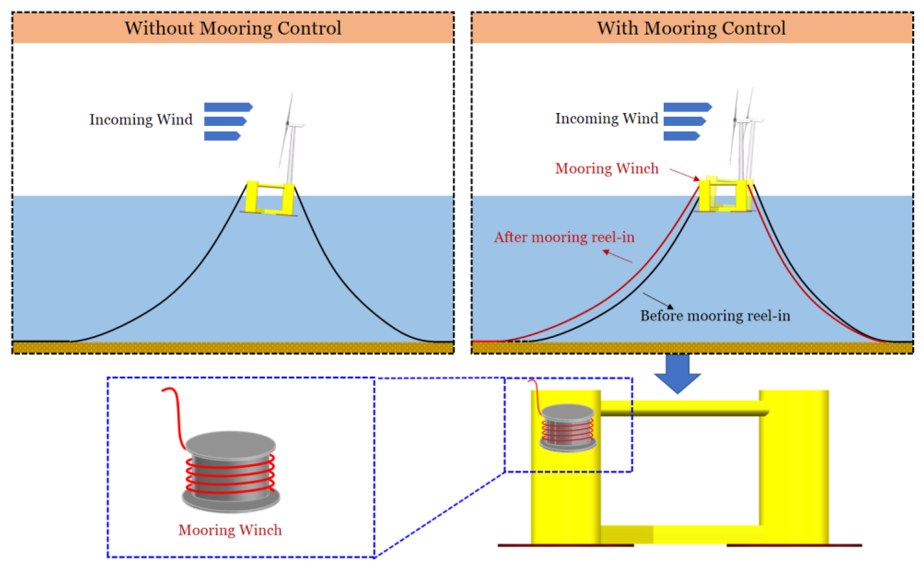
2. Catenary Mooring Length Re-Configuration Control Strategy for FOWTs

The mooring system of FOWTs is used to keep the platform at its desired location avoiding the drift caused by the wind, waves, and currents [38,39]. Furthermore, it also provides restoring forces and moments, as well as a damping effect on the floater motions. Compared with high-cost taut mooring systems, catenary mooring lines made of steel or composite wires are usually favourable for semi-submersible FOWTs. Catenary mooring lines, connecting the fairlead and anchor, will form a catenary curve under their own weight. The platform motion will alter the suspended section of the mooring line, thus leading to the mooring tension variations and providing restoring loads to the floater.
As mentioned above, in this work, the proposed mooring length re-configuration control for the FOWT catenary mooring system is achieved by reeling in or out single or multiple mooring chains with the installed winch systems, as illustrated in Figure 1. Consequently, the suspended mooring length will be altered, leading to an increase or decrease in mooring tensions, so that restoring moments could be enhanced. Notably, the mooring winch usually operates at a low bandwidth compared to the platform motion and turbine dynamics, with a response time in the order of minutes, so the mooring length re-configuration control system in this work aims to reduce the mean downwind platform pitch angle. More specifically, similar to the hull trimming system in [25], the restoring moment produced by properly altering the mooring length is mainly used to compensate the wind-induced static loads, so that the FOWT system could be configured into a more upright position, and thus better structural load behaviours could be anticipated. It should be noted that the heavy-duty mooring winches work in a period of minutes or even hours, and are supposed to be operating at a stationary state. Therefore, the winch dynamics within the mooring reel-in or reel-out processes are not considered in this work, which will be investigated in future works.
Under operating conditions, changes in mean wind speed and direction will lead to variations in aerodynamic thrust, which in turn will cause alterations of the wind load overturning moments. Then, mooring length re-configuration control systems could be enabled to achieve static load balance, so that there will be a smaller downwind tilting of the turbine structures. For instance, as shown in Figure 1, when the aerodynamic overturning moment increases, the front mooring line could be reeled in, providing an additional restoring moment and recovery stiffness to ensure static load balance. In this work, we will quantitatively investigate the relationship between mooring length alternation and the motion mitigation performance. Moreover, it should be noted that the proposed control strategy for catenary mooring system could be achieved either by a single mooring length re-configuration control (SMLC) or multiple mooring length re-configuration control (MMLC), where the lengths of all the three mooring lines are simultaneously changed. In the next section, the influences of mooring length adjustment on FOWT motion dynamics are quantitatively evaluated in fully coupled simulations.

3. Numerical Simulations and Analysis

In this work, fully coupled aero-hydro-servo-elastic FOWT numerical simulations based on OpenFAST [40] have been conducted for both the SMLC and MMLC mooring control configurations with different mooring length alterations, and the control effectiveness on motion mitigation of FOWT are evaluated. The simulation time for each environmental condition is set as 7200 s.

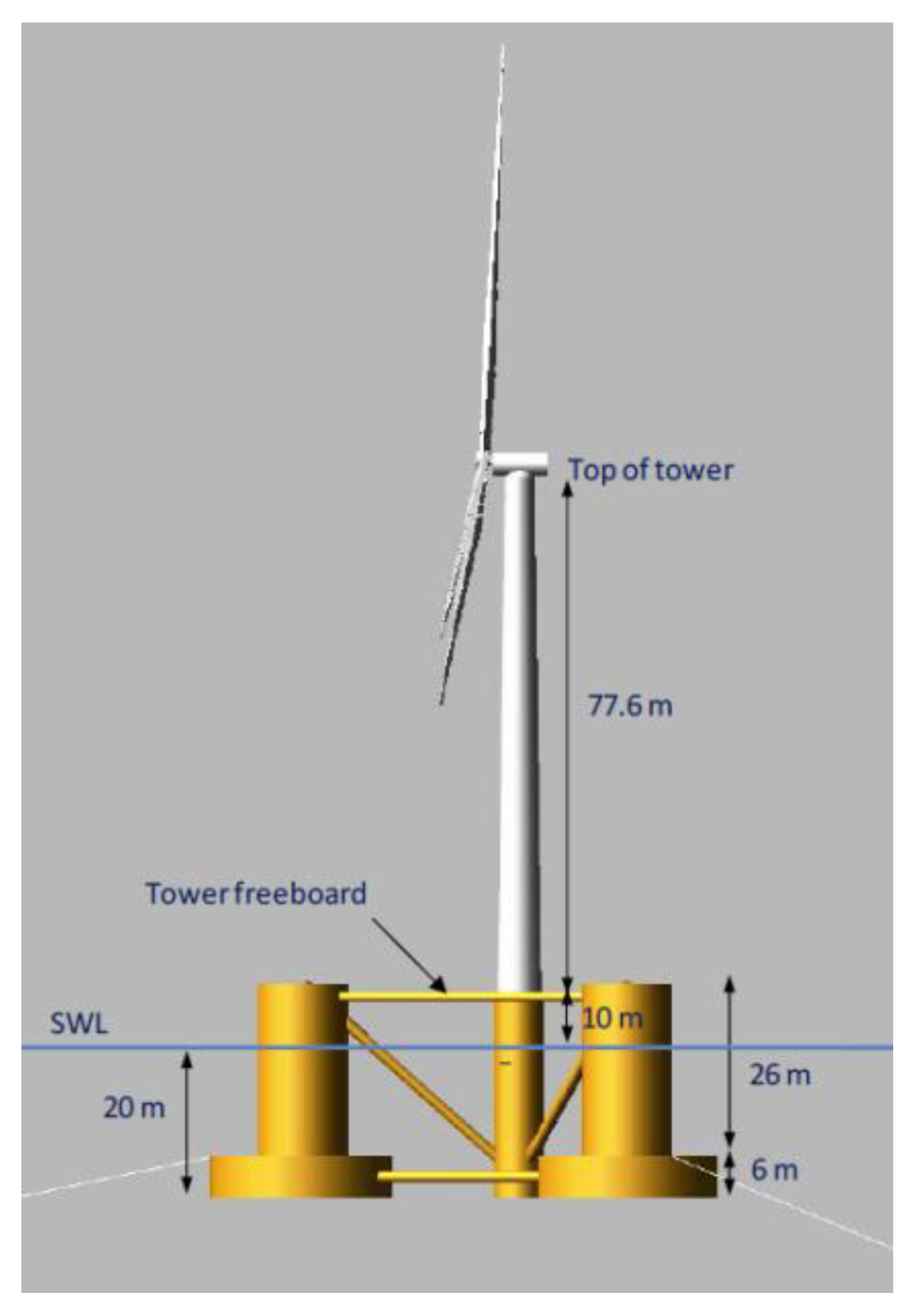
3.1. Semi-Submersible FOWT

The semi-submersible floater of the OC4-DeepCwind developed by National Renewable Energy Laboratory (NREL) is used as the study object in this work [41]. As shown in Figure 2, the platform consists of a main column attached to the tower and three offset columns connected to the main column through a series of pontoons and cross members. The NREL 5 MW baseline wind turbine [42] is supposed to be mounted on the central column.
The water depth for OC4 semi-submersible by default is 200 m. Since the water depth along the eastern and southern coasts of China usually does not exceed 100 m, the mooring system of OC4 is modified as 50 m in this work, as shown in Figure 3. A substantial difference lies in that the fairlead location has been lifted to the top of the column, in order to achieve good mooring performances in waters with medium depth. The primary parameters for the mooring system are listed in Table 1.

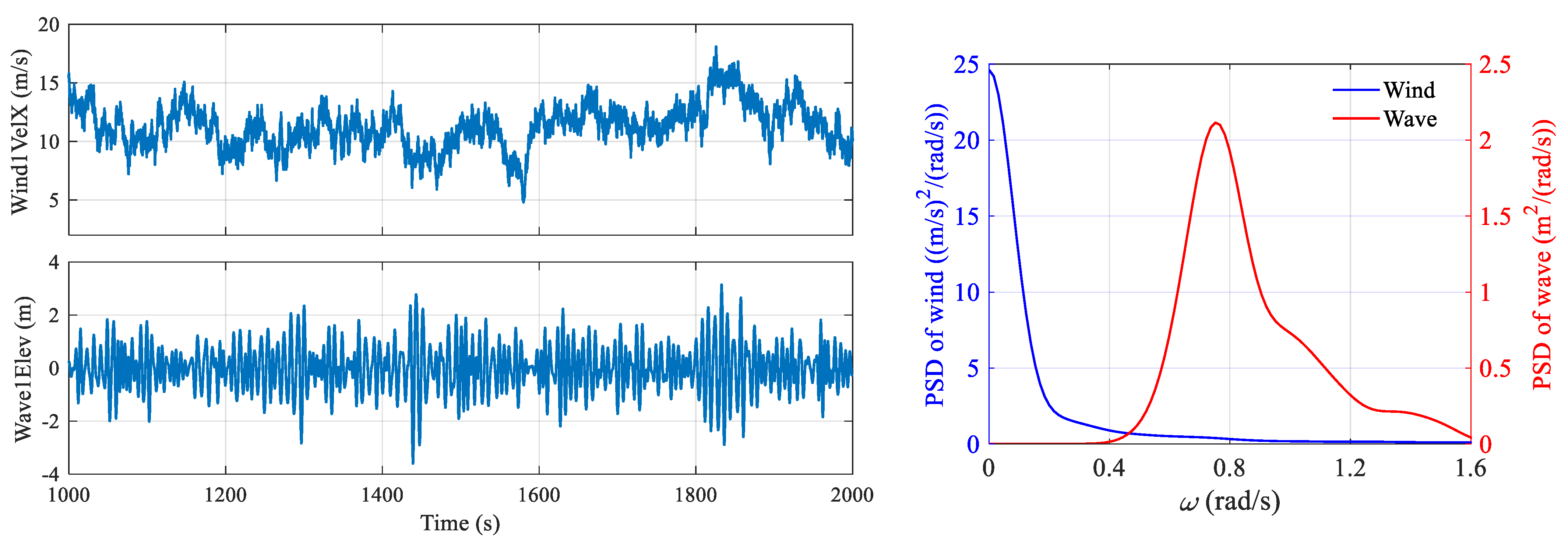
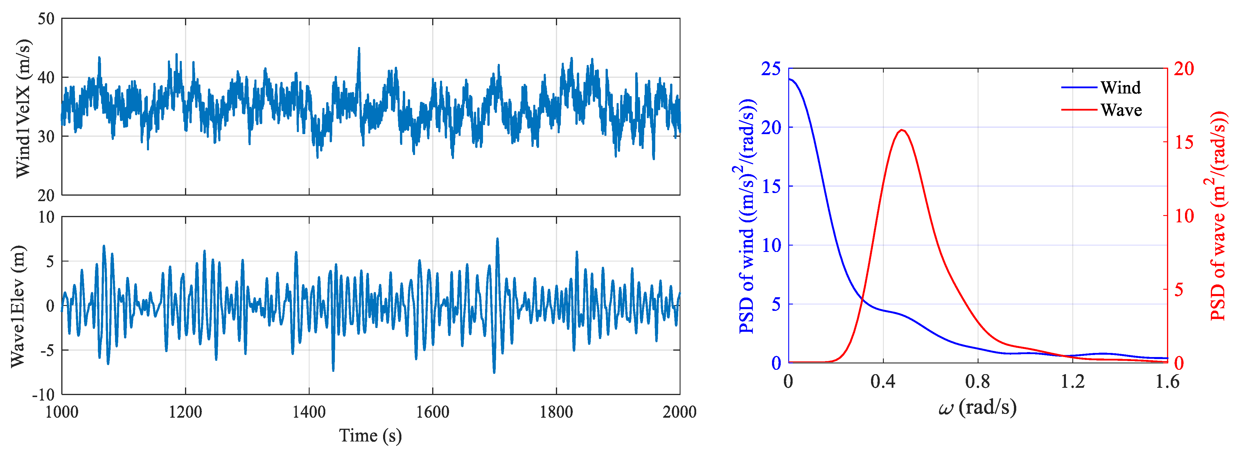
3.2. Environmental Conditions

The following environmental conditions listed in Table 2 are used in the numerical simulations [27]. The rated condition with 11.4 m/s wind speed and 3.8 m significant wave height is used as the wind turbine structures are experiencing the most severe aerodynamic loads in operation. The time-series of the wind speed and wave height are plotted in Figure 4. The wind field is generated by TurbSim [43], where Kaimal spectra and the power law exponent of 0.14 are used according to the IEC61400-3 offshore wind turbine design standard. The normal turbulence intensity is set as level B, i.e., 15%. For wave condition, JONSWAP spectrum is utilized to generate the stochastic wave inputs, the spectrum of which is defined as
S ( f ) = α g 2 16 π 4 f 5 e x p 5 4 f f m 4 γ b ,
where f is frequency, fm denotes the peak frequency, and g is the gravitational acceleration. The shape of the JONSWAP spectrum is mainly dependent on the energy scale parameter α , the peak enhancement factor γ , and the narrowness of the peak b. For the rated condition, the significant wave height is set as 3.8 m, and the peak period is 8.3 s, γ is set as 2.35, according to the wind and wave correlation [26]. Regarding the extreme condition, the parked scenario with 35 m/s wind speed with 8% turbulence intensity, 0.11 power law exponent, and 10.3 m significant wave height with 14.1 s peak wave period, as shown in Figure 5, is also used to verify the mooring control effectiveness. In this parked case, the generator torque and blade pitch controller are turned off, and all the blades are feathered to 90 degrees to minimize the aerodynamic loading. Regarding mooring control configuration in this work, the line length is supposed to be reeled in ranging from 0 to 15 m at an interval of 2.5 m for both the SMLC and MMLC configurations, and then comparative investigations are performed.

3.3. Coupled Numerical Modelling Methodology

In this work, numerical simulations for semi-submersible FOWTs have been conducted using the well-known open-source code OpenFAST [40], which is a multi-physics tool for simulating the coupled dynamic response of wind turbines. It couples computational modules for aerodynamics, hydrodynamics, the control and electrical system (servo) dynamics, and structural dynamics, as well as mooring dynamics, to enable coupled nonlinear aero-hydro-servo-elastic simulation in the time domain.

3.3.1. Multi-Body Dynamics

Regarding the theory used in OpenFAST, Kane’s method is adopted to derive the multi-body equations of motion for a wind turbine system with P generalized coordinates (DOFs), i.e.,
F i + F i * = 0   ( i = 1 ,   2 , . . . P )
where F i and F i * are generalized active forces and generalized inertia forces, respectively.

3.3.2. Aerodynamics

The aerodynamic loads imposed on the wind turbine rotor are affected by many factors, such as wind speed and direction, blade pitch angle, platform motion, and blade elasticity. In OpenFAST, blade element momentum (BEM) theory is used for aerodynamic calculation, in which the blades are divided into a number of independent sections along the length, and sectional lifts and drags are evaluated and integrated into the overall thrust and torque [36]. For a given blade profile, the lift and drag coefficients CL and CD are defined by:
d L = C L ( α ) 1 2 ρ U r e l 2 C λ d r
d D = C D ( α ) 1 2 ρ U r e l 2 C λ d r
where ρ is the mass density of the fluid, dL and dD are the elementary lift and drag forces applying to a blade element of thickness dr and of chord C λ . The parameter α is called angle of attack and defined as the angle between the chord and flow direction.

3.3.3. Hydrodynamics

Hydrodynamic loads on offshore wind systems include contributions from linear hydrostatics, linear excitation from incident waves, linear radiation from outgoing waves (generated by platform motion), and nonlinear effects. Regarding the simulation in this work, hydrodynamics of the OC4-DeepCwind platform is calculated based on linear potential flow theory with viscosity correction, which has been widely used for large-scale offshore structure analysis. It is assumed that flow is inviscid, incompressible, and irrotational. The added mass, radiation damping, and viscous drag effect are included.
Then, the overall motion equation of the FOWT can be represented by:
( M + A ) x ¨ ( t ) + C x ˙ ( t ) + K ( t ) + 0 t R ( t τ ) x ˙ ( τ ) d τ = F a e r o ( t ) + F h y d r o ( t ) + F m o o r i n g ( t )
where M is the platform mass, A is the added mass matrix at infinite frequency, C is the damping matrix, K is the stiffness matrix, and R is the velocity impulse function matrix. x denotes the displacement vector. The external loadings include the aerodynamic loads F a e r o , hydrodynamic loads F h y d r o , and the mooring loads F m o o r i n g .

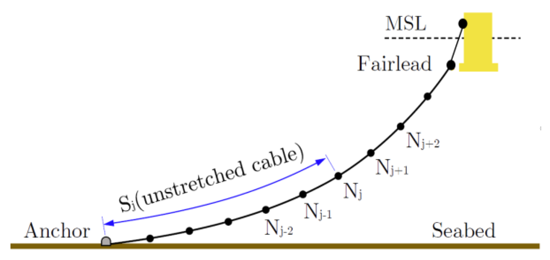
3.3.4. Mooring Dynamics

The lumped-mass approach is adopted for modelling the FOWT mooring system. As a sub-module, MoorDyn in OpenFAST models the mooring dynamics based on a lumped-mass discretisation of a mooring line’s dynamics and adds point-mass and rigid-body objects to enable simulation of a wide variety of mooring and cabling arrangements. The dynamic nonlinear catenary mooring line model is established as multi-segment elastic catenary lines with several sections and clump weight, which is illustrated in Figure 6.

3.4. Numerical Simulation Results and Analysis

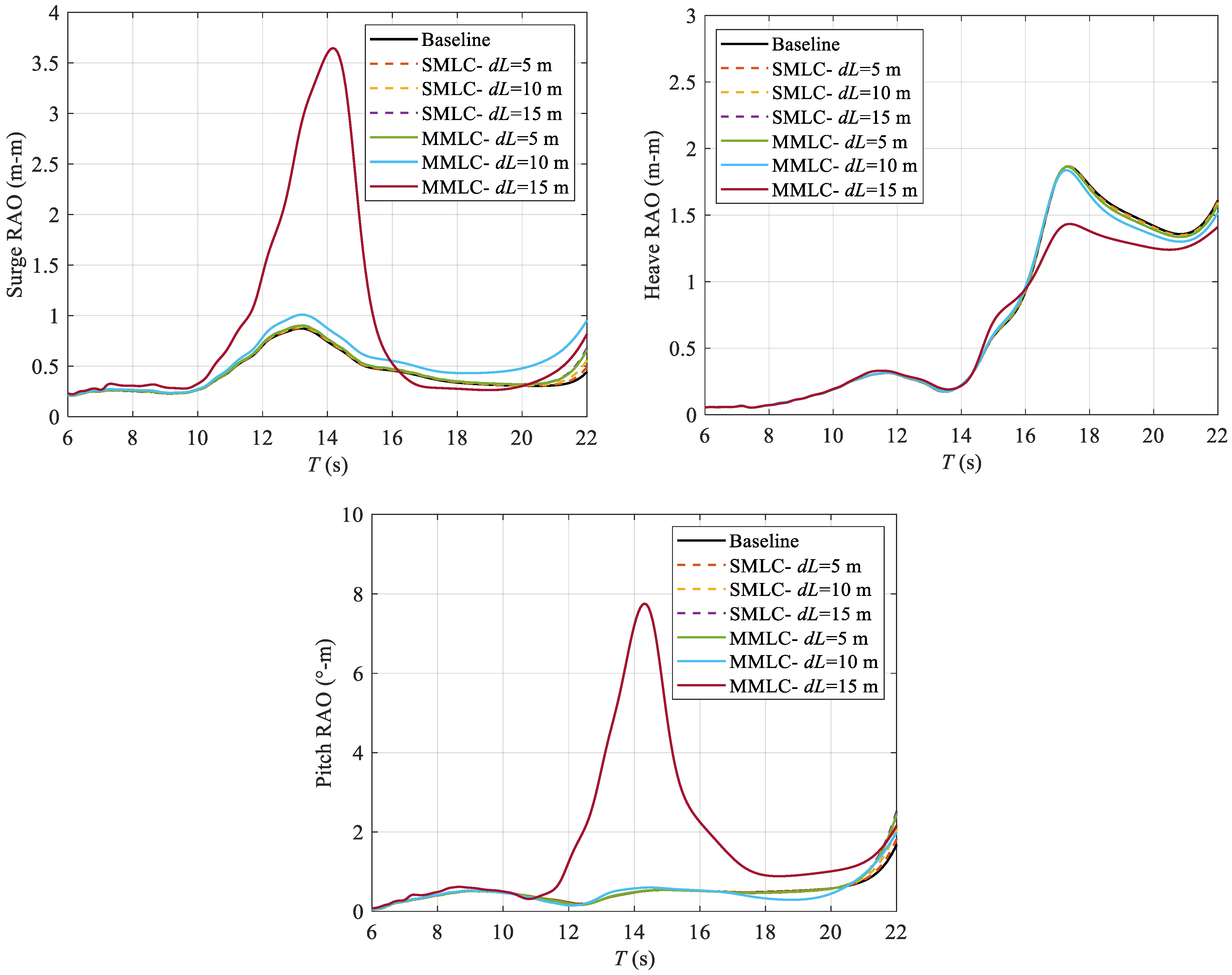
3.4.1. Response Amplitude Operator (RAO)

The RAO results for different mooring length configurations are shown in Figure 7. It can be noted that the MMLC with 15 m has led to large peaks for surge and pitch motion, as the mooring lines have become taut in this scenario. In comparison, there are no significant differences between the baseline system and the re-configured mooring design.

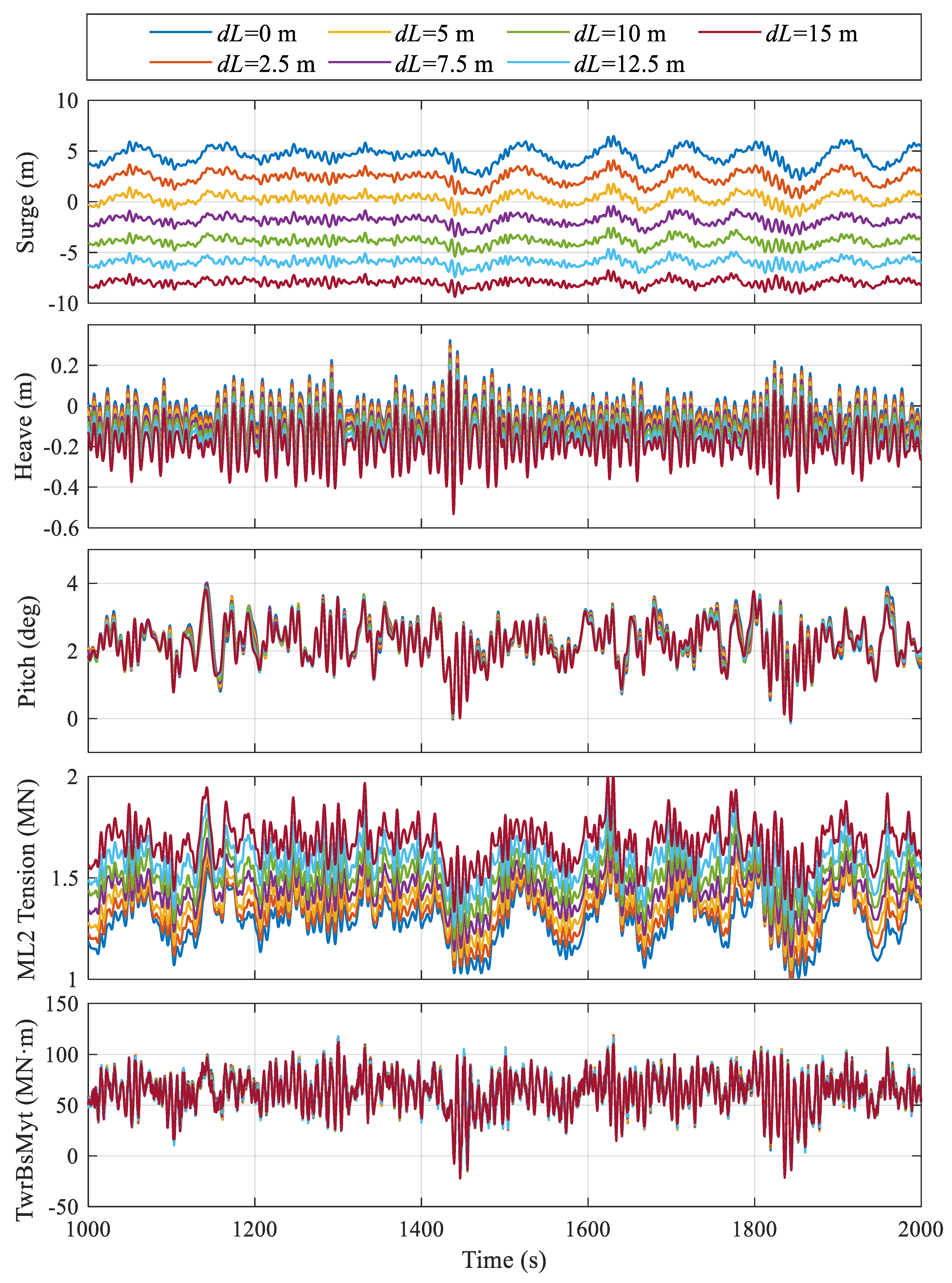
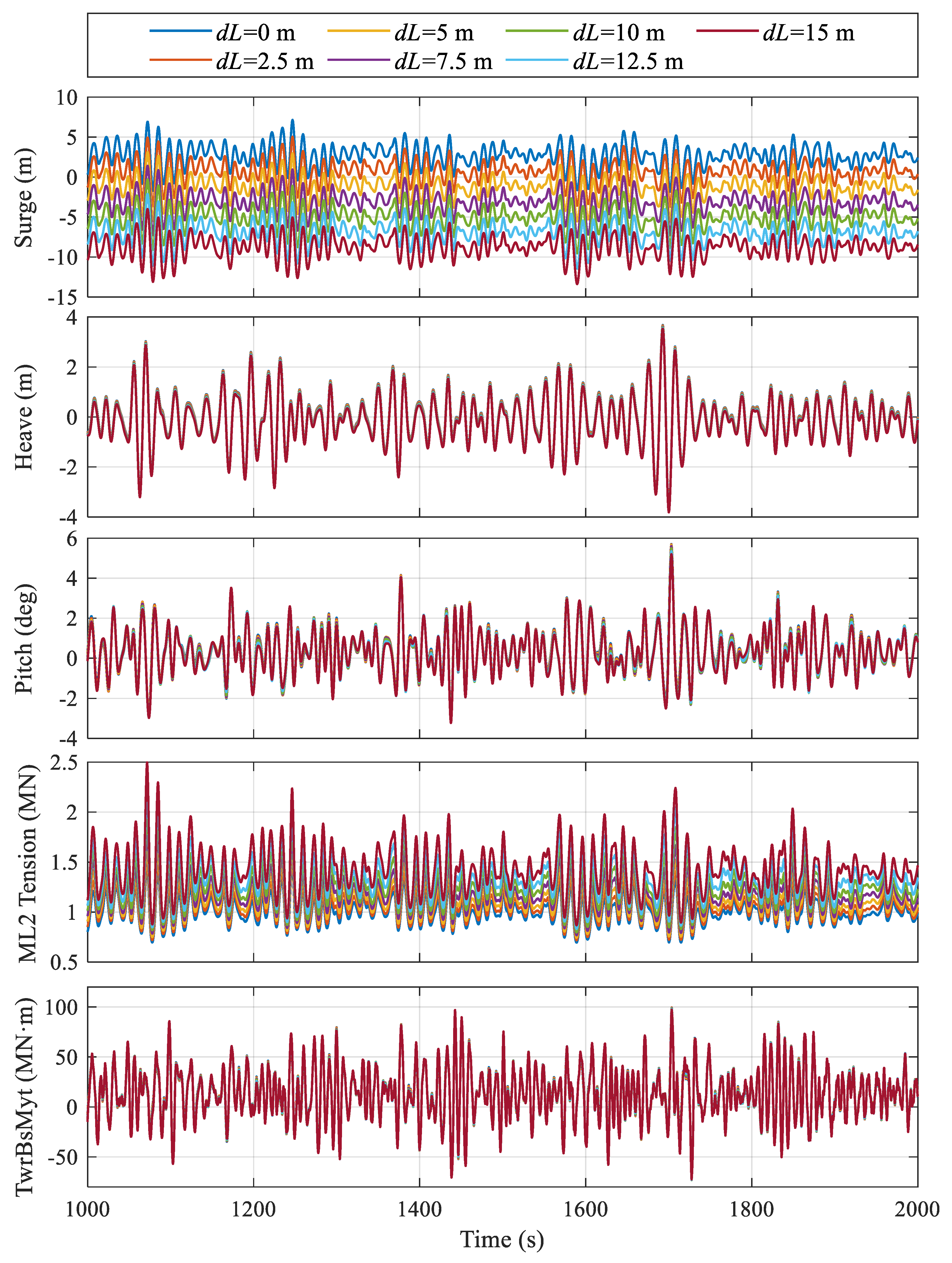
3.4.2. Rated Condition

Regarding the SMLC, the ML2 attached to the upwind column is reeled in. In this paper, dL is defined as the reel-in length, e.g., dL = 5 m means the mooring is reeled in 5 m. It is shown in Figure 8 and Figure 9 that the SMLC has a significant impact on the average surge position, which changes from 4.50 to −7.97 m by retracting the mooring length for 15 m. At the same time, heave and pitch motion does not show any noticeable differences. In contrast, for MMLC, all the three moorings are reeled in at the same length, such that surge motion does not exhibit any large shifting, while the equilibrium heave position is decreased by 1 m.
Statistical results of the above motion time-series are illustrated in Figure 10, Figure 11 and Figure 12. Regarding platform surge motion, the SMLC will lead to a smaller standard deviation as the mooring line keeps shortening, and a maximum of 50% reduction could be achieved, while for the MMLC, the surge standard deviation falls first and then rises. This is because when all the three mooring lines are retracted for 12.5 m, the catenary mooring will be close to taut mooring, which will cause large load variations, posing risks to anchor failures. In addition, the maximum and minimum surges continue to decrease as the mooring lines are shortened. Regarding platform heave motion, both the SMLC and MMLC will lead to a reduced heave equilibrium position, while the MMLC has a much larger influence on the heave motion, which is simply because of the significantly increased vertical mooring tensions. Heave standard deviation is almost not affected, as it is dominated by the column geometries of the floater. Regarding platform pitch motion, it can be clearly seen that the mean pitch angle keeps decreasing for the SMLC, but only a 0.1° pitch reduction is achieved, which is far from the assumed zero tilting. The average pitch for the MMLC shows a slightly different trend, i.e., rising first and then falling, but the mean pitch reduction is still quite small. This means that it is quite difficult to achieve zero mean pitch by catenary mooring control. In comparison, pitch standard deviation could be reduced by 5.1% for the SMLC, and this number could reach 15.8% for the MMLC. This demonstrates that the proposed mooring control strategy is helpful in mitigating the floater pitch oscillations.
Power spectrum analysis is also performed, and the obtained power spectrum densities (PSDs) are plotted in Figure 13. It can be clearly seen that the natural frequency response of the surge motion is heavily suppressed by reducing the mooring line length both for the SMLC and MMLC, which is consistent with the above time-domain results. The heave PSD has almost no variations with mooring control actuated, which shows that active mooring has little effect on heave motions. Regarding pitch motion, the introduction of the SMLC helps reduce the pitch natural frequencies to a certain extent, while the wind and wave frequency responses are almost not affected. This corresponds to the above findings that the platform mean pitch decreases only by a very small amount, but pitch oscillation is noticeably suppressed. In contrast, the MMLC has a much stronger influence on pitch PSDs. In particular, the pitch natural frequency response has been inhibited to a very low level, contributing to the decreased pitch oscillations. However, wind and wave frequency responses may rise when the mooring line is retracted 10 m more, and at this time, the catenary mooring will be close to taut mooring. In particular, there exist a large peak around 0.15–0.2 rad/s, and this will cause large load variations.
Tower-bottom fore-aft bending moments are also evaluated in order to check the mooring control influences on structural fatigue loads, and the statistical results for load reduction with different mooring length configurations are shown in Figure 14. Here, a positive number means load increment, while a negative number signifies a load reduction. It is seen that with the SMLC, the average bending moments increase negatively when the mooring lines are reeled in, while the load is increased first and then decreased for the MMLC. This phenomenon agrees well with the above statistical results for pitch motion. Regarding standard deviation, both the SMLC and MMLC will worsen the results, which may be harmful to the tower-bottom fatigue.
Statistical results of ML2 tensions are shown in Figure 15. It can be observed that the SMLC will not heavily affect the mooring loads, but the MMLC will cause a substantial increase in the mean values of mooring tensions. Regarding standard deviations, both SMLC and MMLC will lead to decreased oscillation first and rise again by increasing the retracted mooring length.

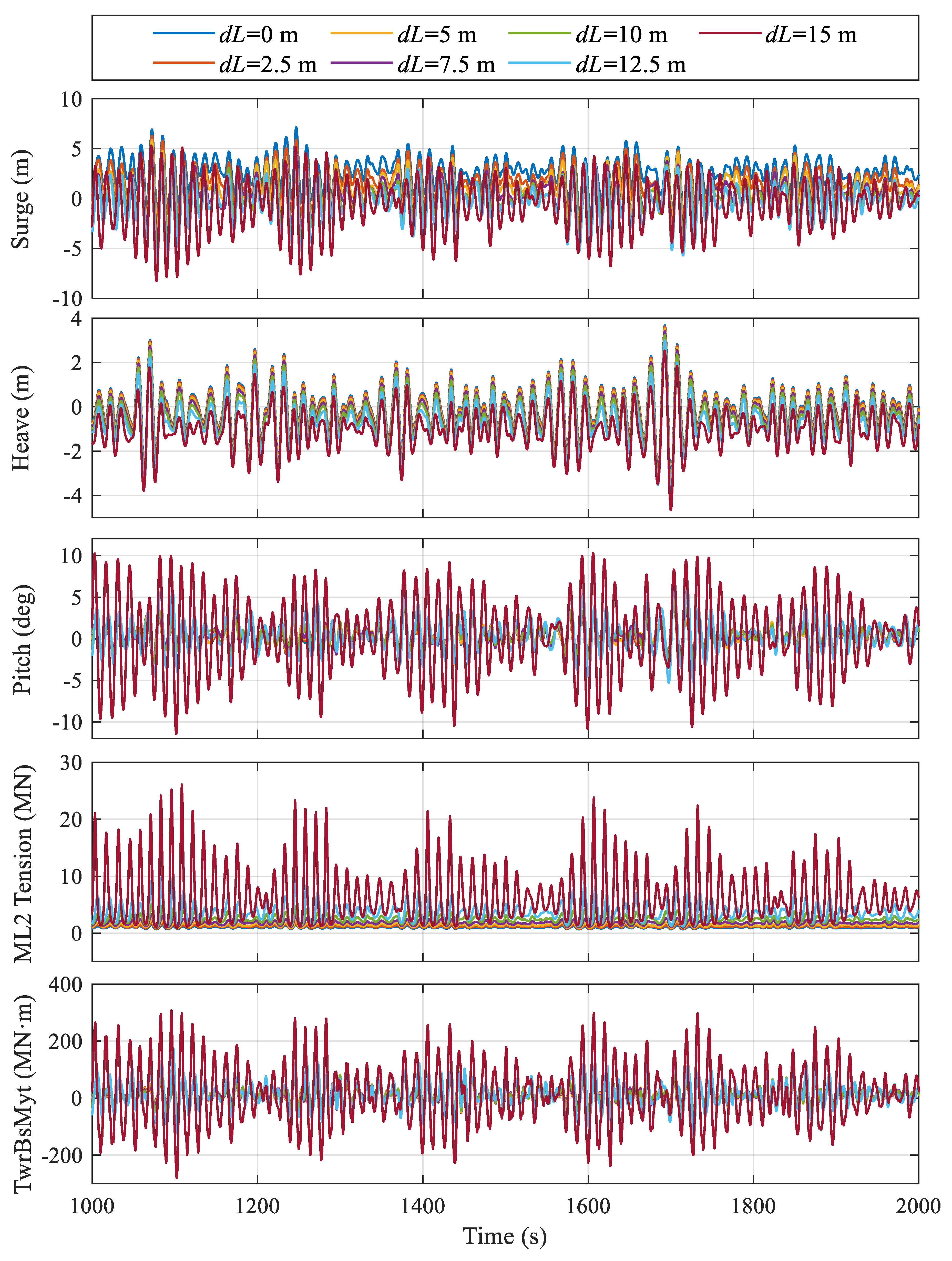
3.4.3. Parked Condition

Regarding the extreme condition with 35 m/s turbulent wind speed, there will be less aerodynamic thrust on the rotor as the blades are all feathered, but the sea state will be much more severe. Similar to the rated condition, it can be seen from Figure 16 that the SMLC has a significant impact on the average surge position, which changes from 2.67 to −8.72 m by retracing the mooring length for 15 m. At the same time, heave and pitch motion does not show noticeable differences. For the MMLC as shown in Figure 17, again the surge motion does not exhibit any large shifting. However, the pitch motion is greatly increased, even reaching the amplitude of 10°. This will pose a risk to the safe operation of FOWT in extreme conditions. It is because the catenary moorings gradually become taut when the length of all mooring lines is reduced over 12.5 m, such that large mooring tension variations will increase platform pitch responses.
Statistical results of the above motion time-series are illustrated in Figure 18, Figure 19 and Figure 20. Regarding the platform surge motion, the standard deviation is almost not affected as the mooring line is shortened, while for MMLC, the surge standard deviation keeps increasing. When all the three mooring lines are retracted for more 12.5 m, the catenary mooring will become almost taut, such that large variations could be seen. Regarding the platform heave motion, both the SMLC and MMLC will lead to a reduced heave equilibrium position, while MMLC has a much larger influence on the heave motion, which is simply because of the significantly increased vertical mooring tensions. Similar to the rated condition, heave standard deviation is almost not affected for the SMLC, while the MMLC will lead to smaller heave oscillations. Regarding the platform pitch motion, it can be seen that the mean pitch angle decreases from 0.4° to 0.3° for the SMLC, and the average pitch for the MMLC shows a different trend but variations are still small. This still means that it is quite difficult to achieve zero mean pitch by catenary mooring control. In comparison, pitch standard deviation is almost not changed for the SMLC, while the pitch standard deviation may be increased by over 100% for the MMLC when the mooring length is shortened over 12.5 m. This is also mentioned in previous time-domain analysis.
Corresponding spectrum analysis results are shown in Figure 21. It can be seen that the surge motion is dominated by wave frequency responses in the parked condition. In this scenario, the SMLC has little influence on surge motion, while in contrast the surge motion is greatly excited when the line length reduction exceeds 12.5 m for the MMLC, which is consistent with the above time-domain results. The heave PSD still has little variation with mooring control. Regarding pitch motion, again the SMLC has almost no noticeable influence on the pitch PSDs. In contrast, the MMLC has led to large platform pitch motions in the wave frequency range. This means the pitch motion would be heavily excited by wave loadings with the mooring becoming taut.
Statistical results for the tower-bottom fore-aft bending moment load reduction with different mooring length configurations are given in Figure 22. It is again observed that with the SMLC, the average bending moments increase negatively when the mooring lines are reeled in, while the load is increased first and then decreased for the MMLC. This phenomenon agrees with the above statistical results for pitch motion. Regarding standard deviation, both the SMLC and MMLC will worsen the results, especially for the MMLC. In terms of the maximum bending moment, the SMLC has over 2% load reduction with 15 m line retraction, while MMLC causes an increase of over 200%, which may violate the design requirements.
Statistical results of ML2 tensions under parked condition are shown in Figure 23. It can be noticed that both the SMLC and MMLC will increase the mean values, standard deviations, maximums, and minimums of the mooring tensions. The excessive usage of mooring tensions is supposed to provide better motion behaviours for the floating platforms, but the magnitude of the mooring tensions should be carefully checked.

4. Conclusions

Control design optimisation is an essential means for FOWT dynamic behaviour improvement. Besides tuning the existing generator torque and blade pitch controller for indirect mitigation, more straightforward motion reduction control mechanisms by introducing additional actuations have been proposed, such as a structural control and active ballasting. In this work, the mooring length re-configuration control for motion mitigation of semi-submersible FOWTs is investigated. Here, the mooring control is supposed to be achieved by altering the mooring length, thus the mooring tensions could be adjusted for better dynamic behaviours. Control designs for both single mooring line and multiple mooring lines have been described and comparatively studied. Aero-hydro-servo-elastic numerical simulations for different environmental load cases have been conducted, where the motion mitigation and load reduction performances of the proposed mooring length control methods are evaluated. The following conclusions can be drawn based on the study:
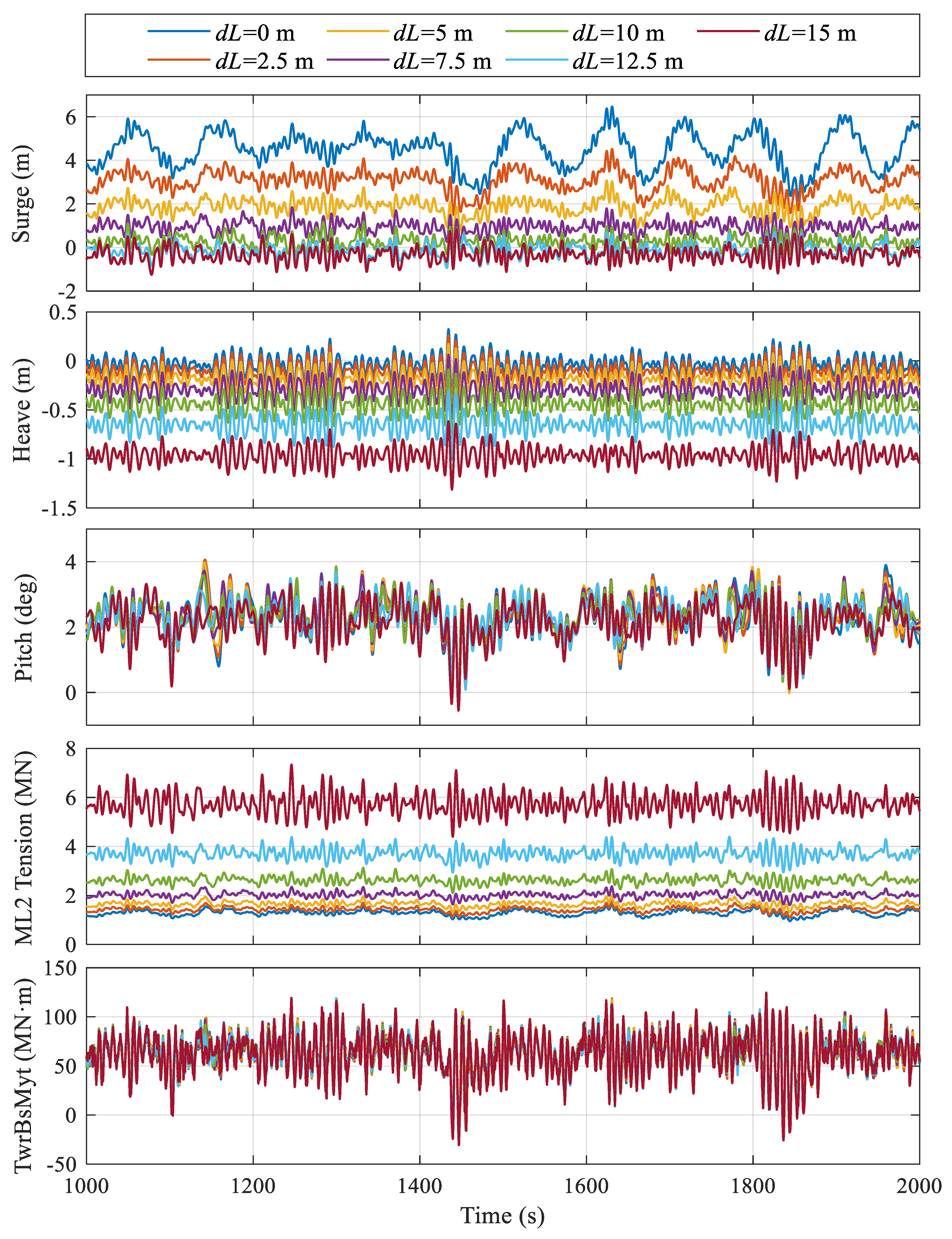
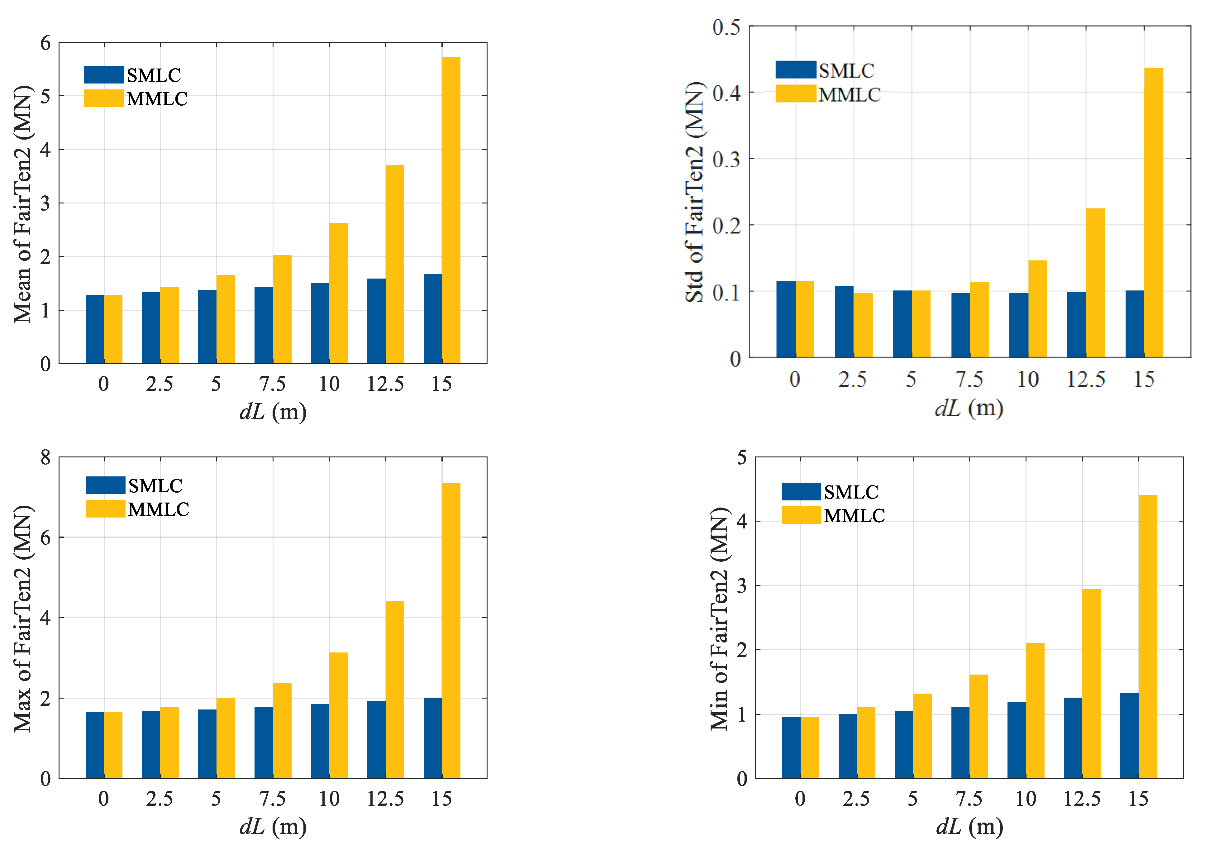
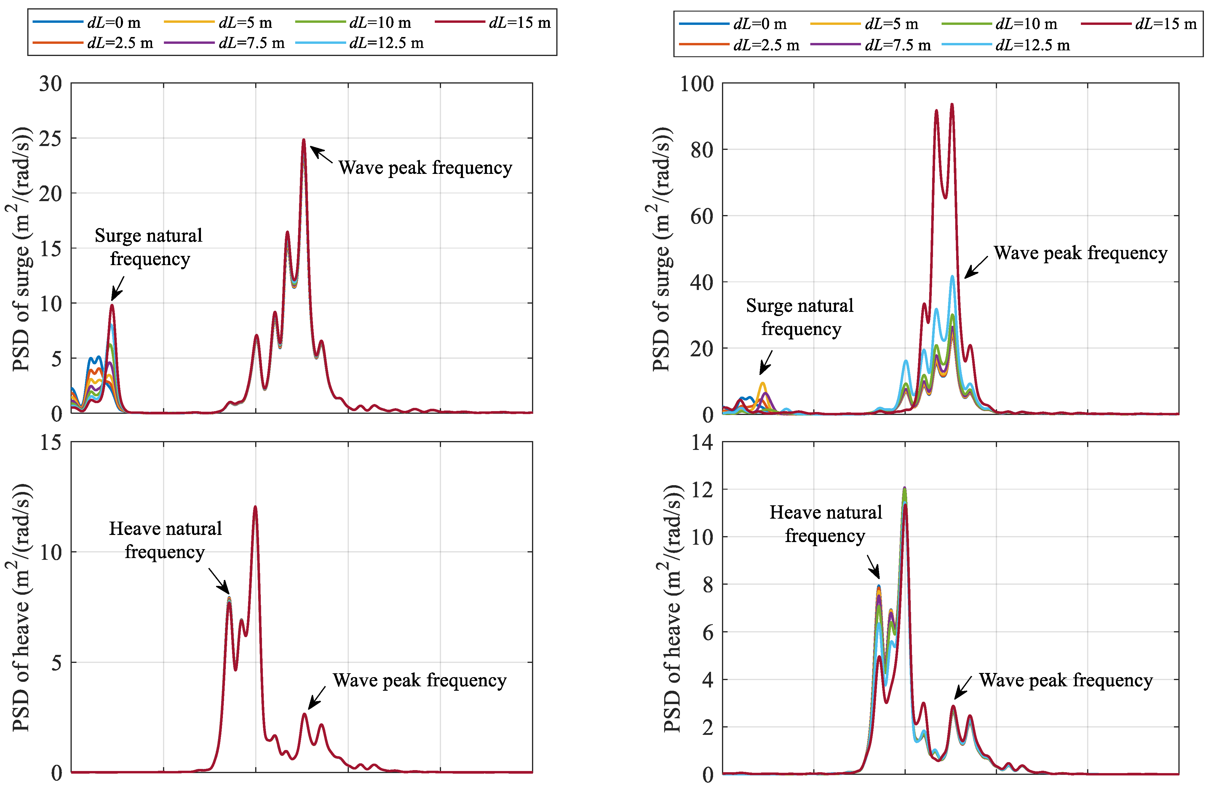
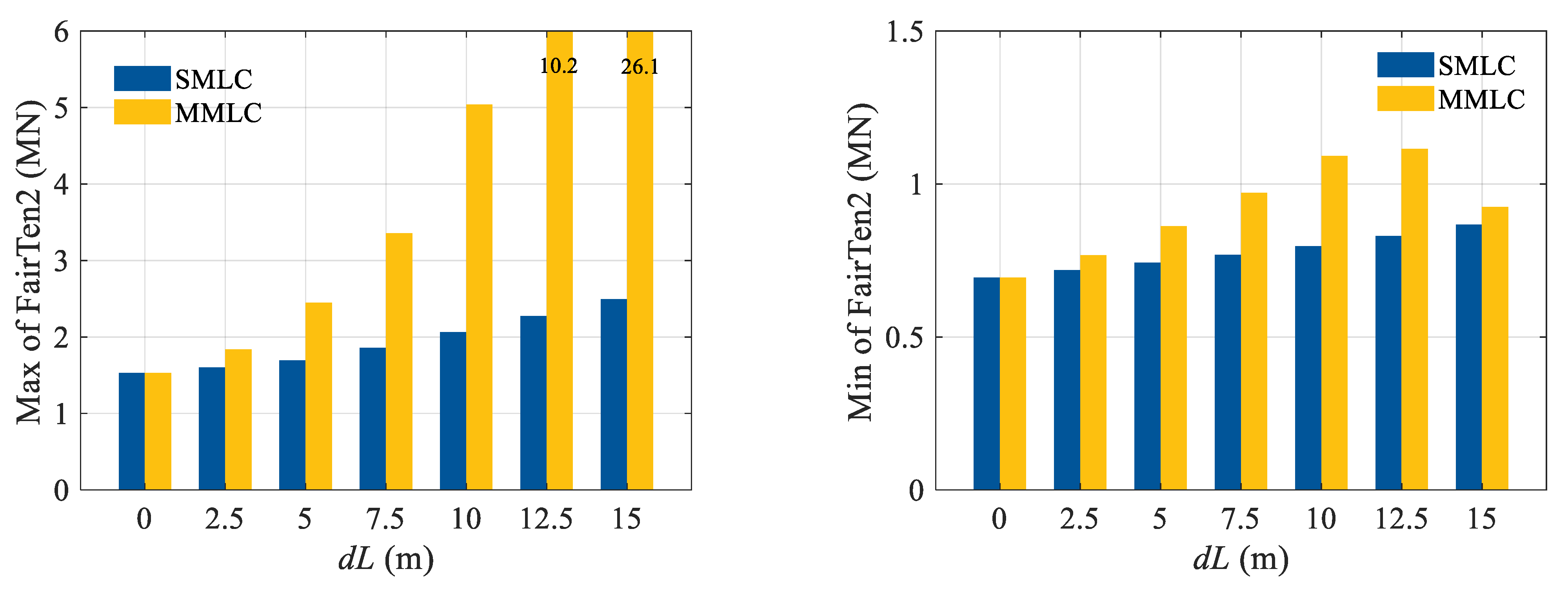
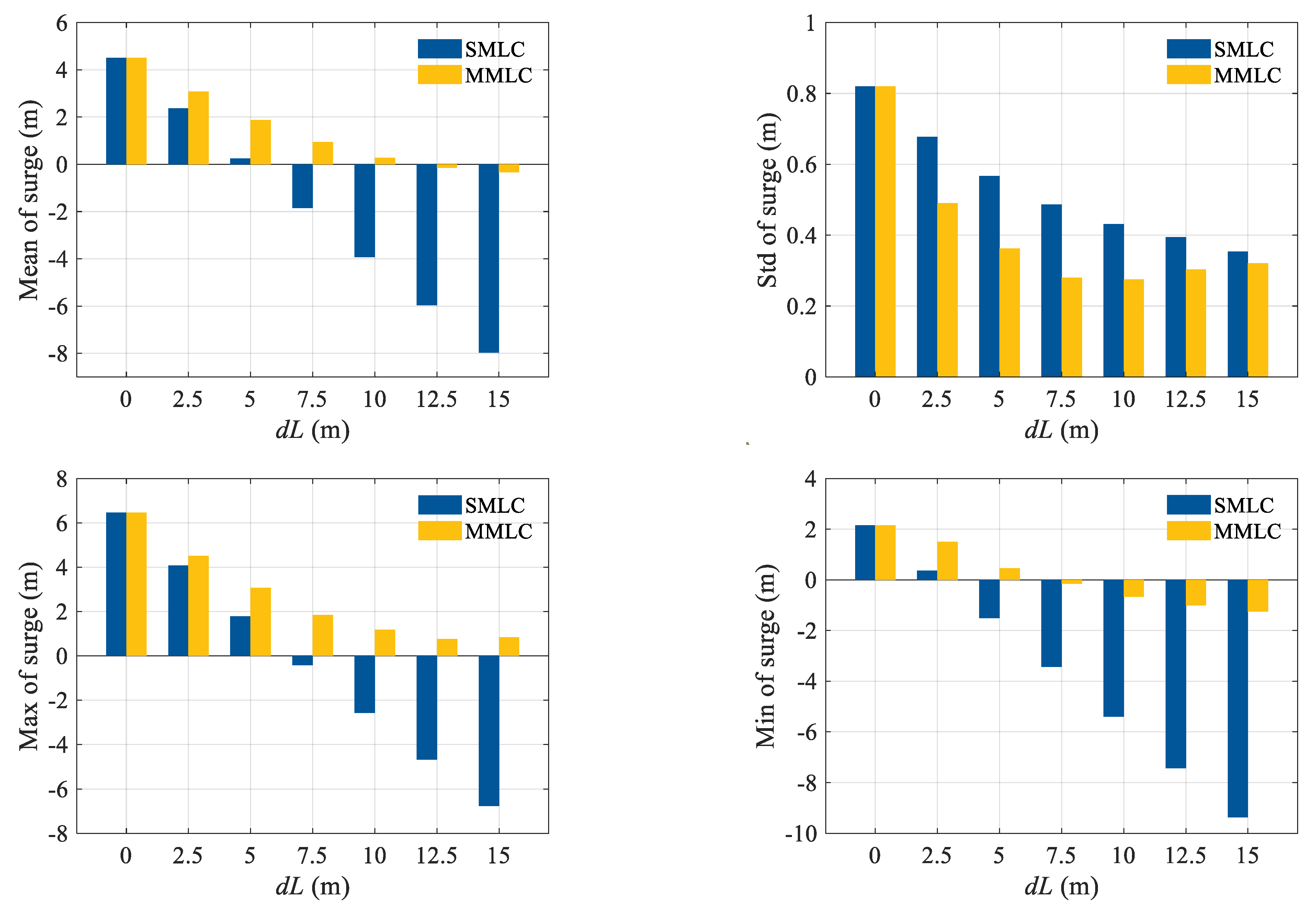
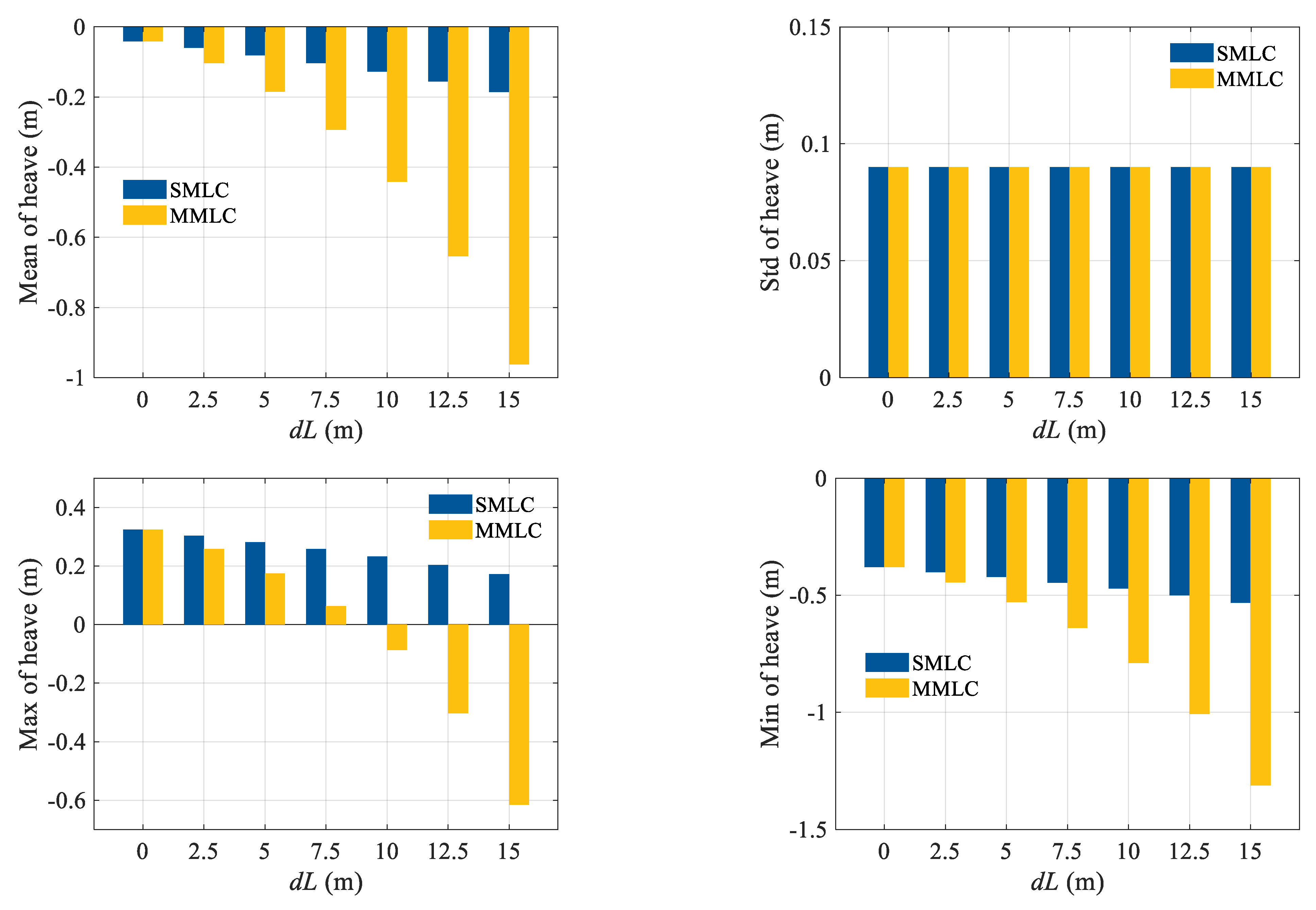
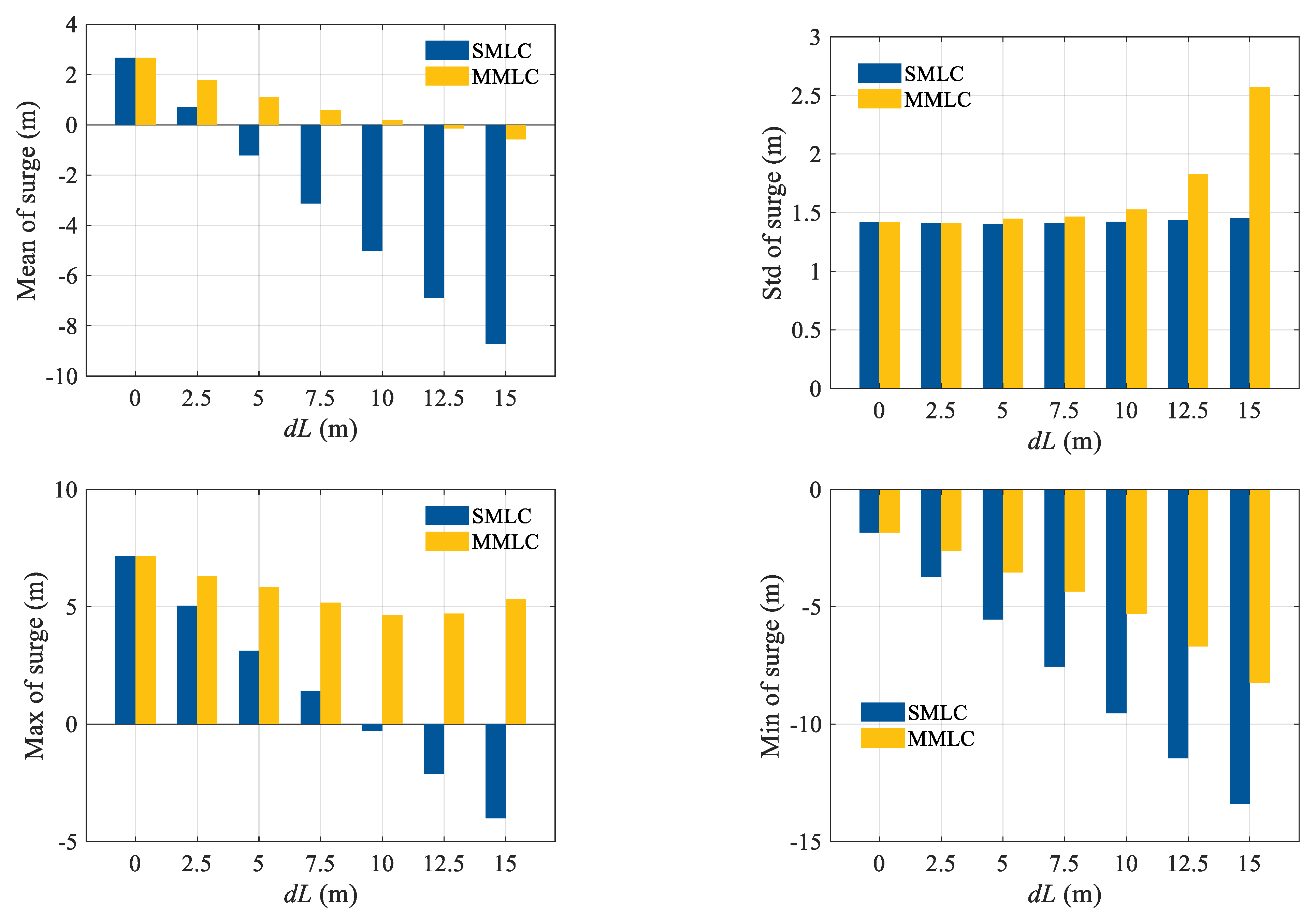
  • The SMLC will result in a substantial change in platform surge motion due to the asymmetric mooring configuration under the rated conditions. For the MMLC, the surge standard deviation will rise when all the three mooring lines are retracted for more 12.5 m.
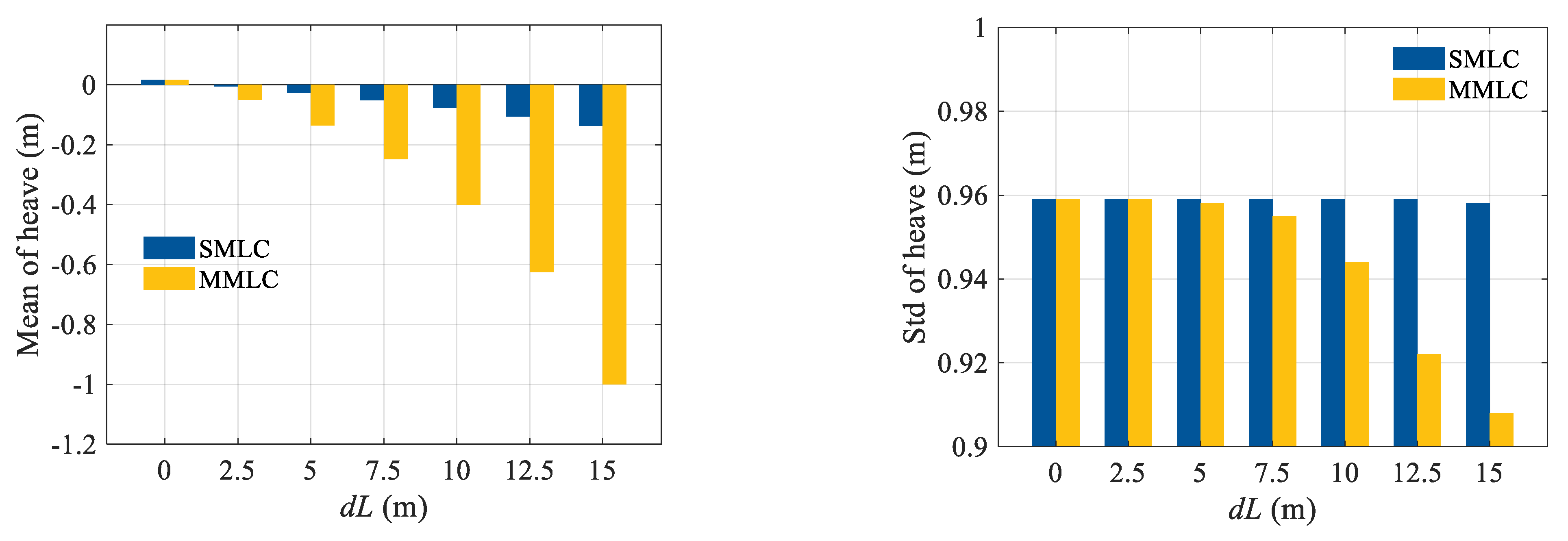
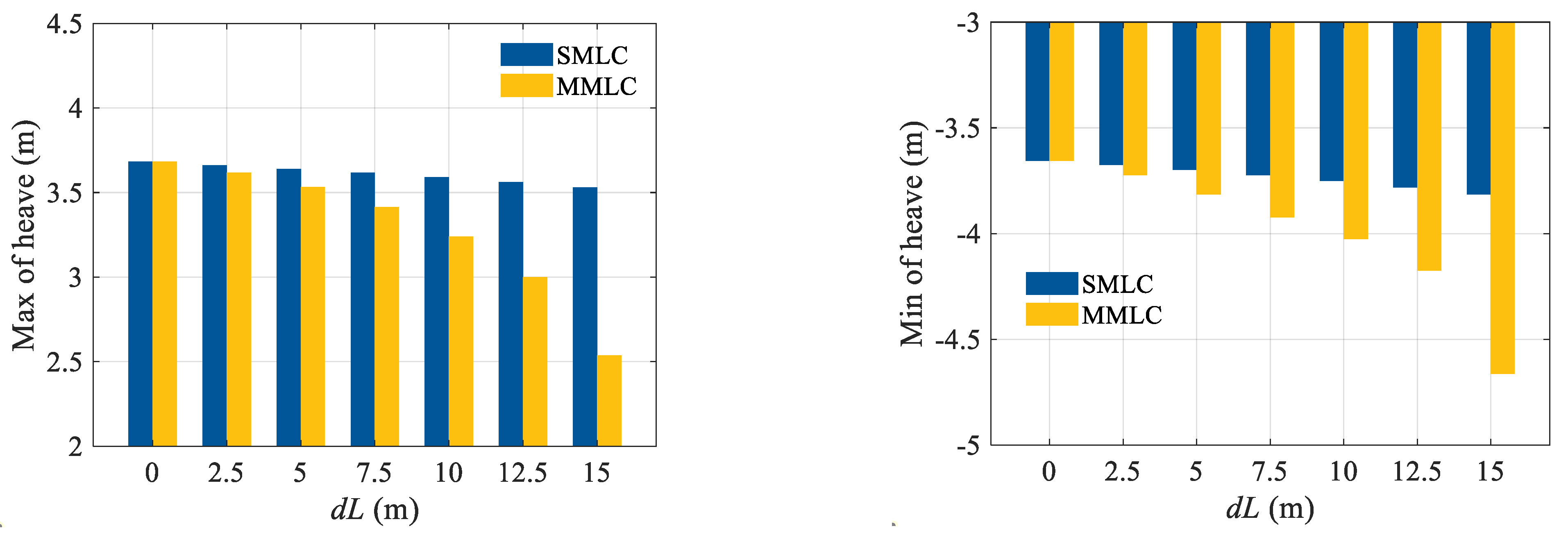
  • Platform heave motion is not affected much by the catenary mooring control, as it is dominated by the column geometries of the floater.
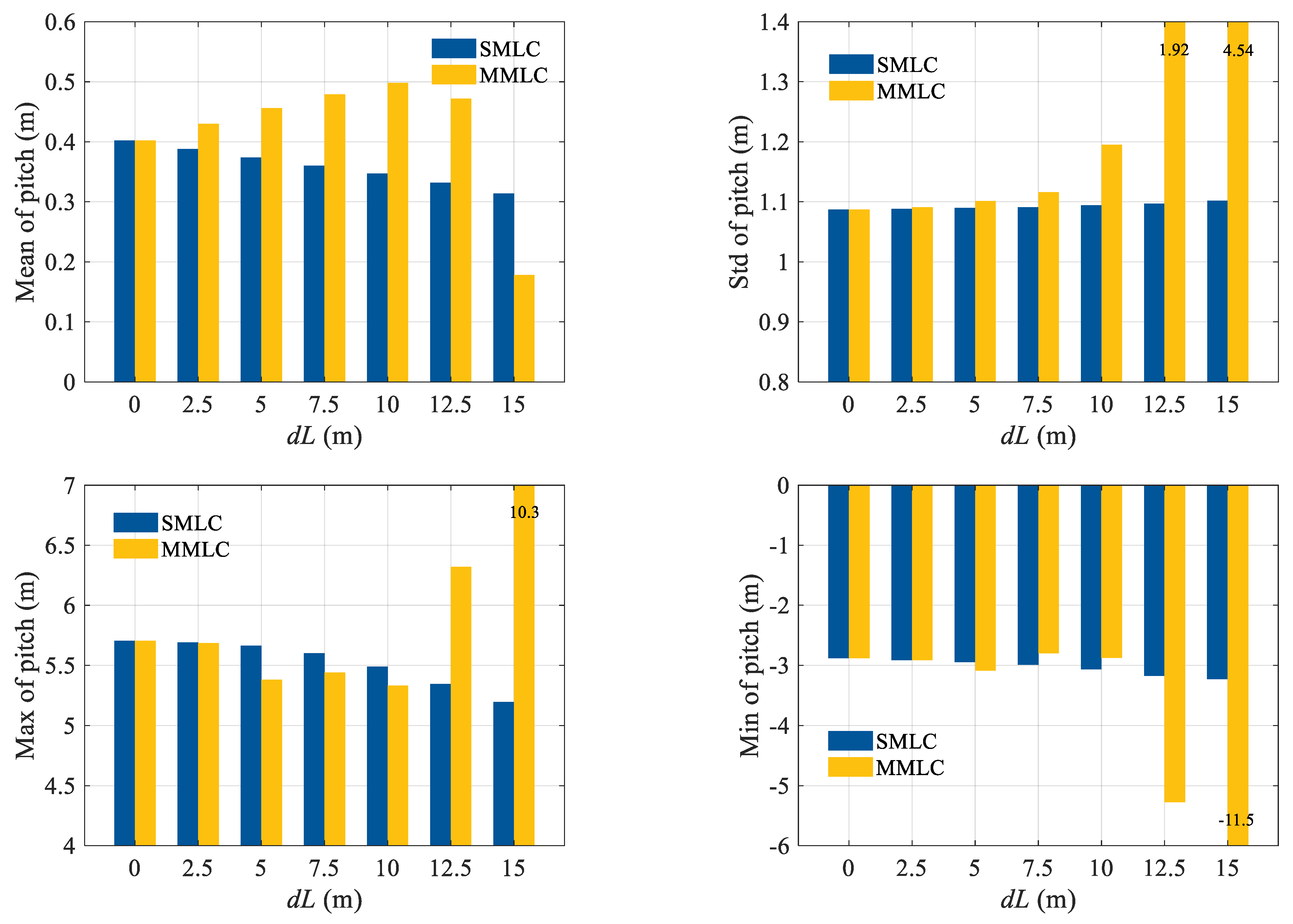
  • Only 0.1° mean pitch angle reduction is achieved, which is a bit far from the assumed zero tilting, meaning it is quite difficult to achieve zero mean pitch by catenary mooring length re-configuration.
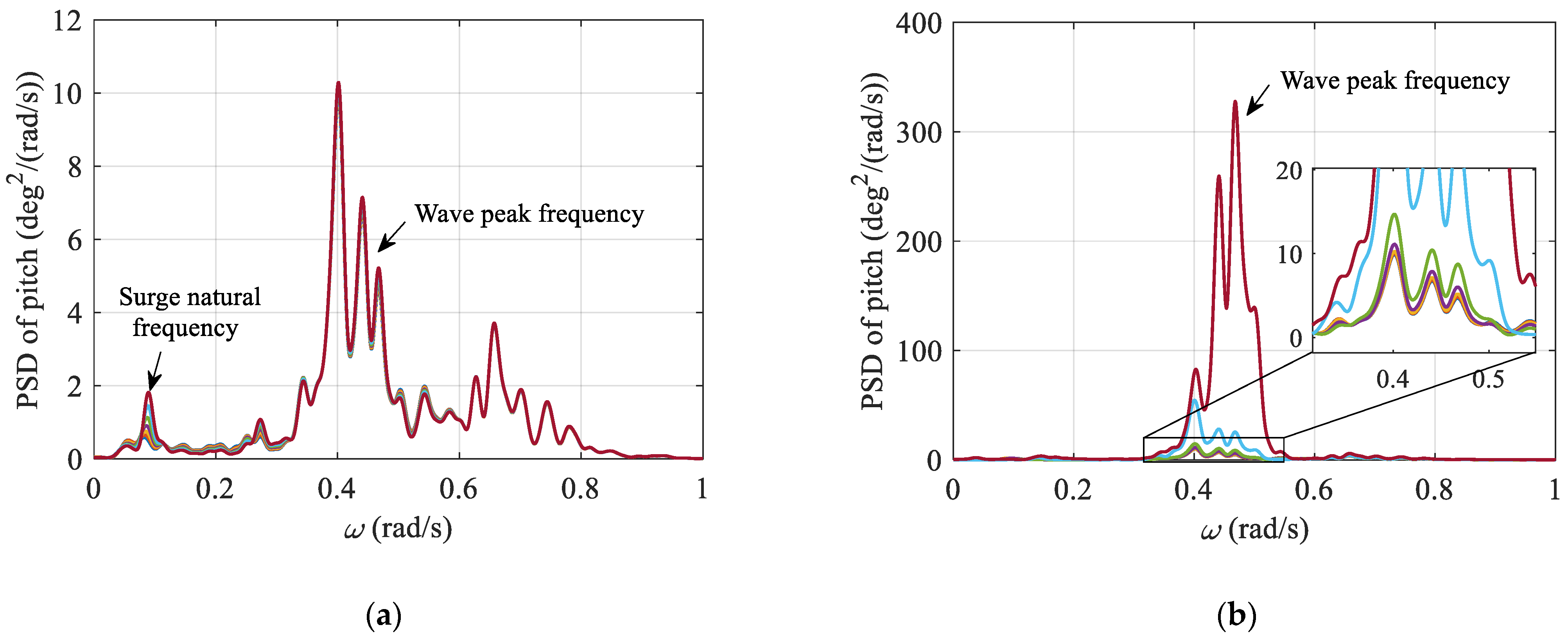
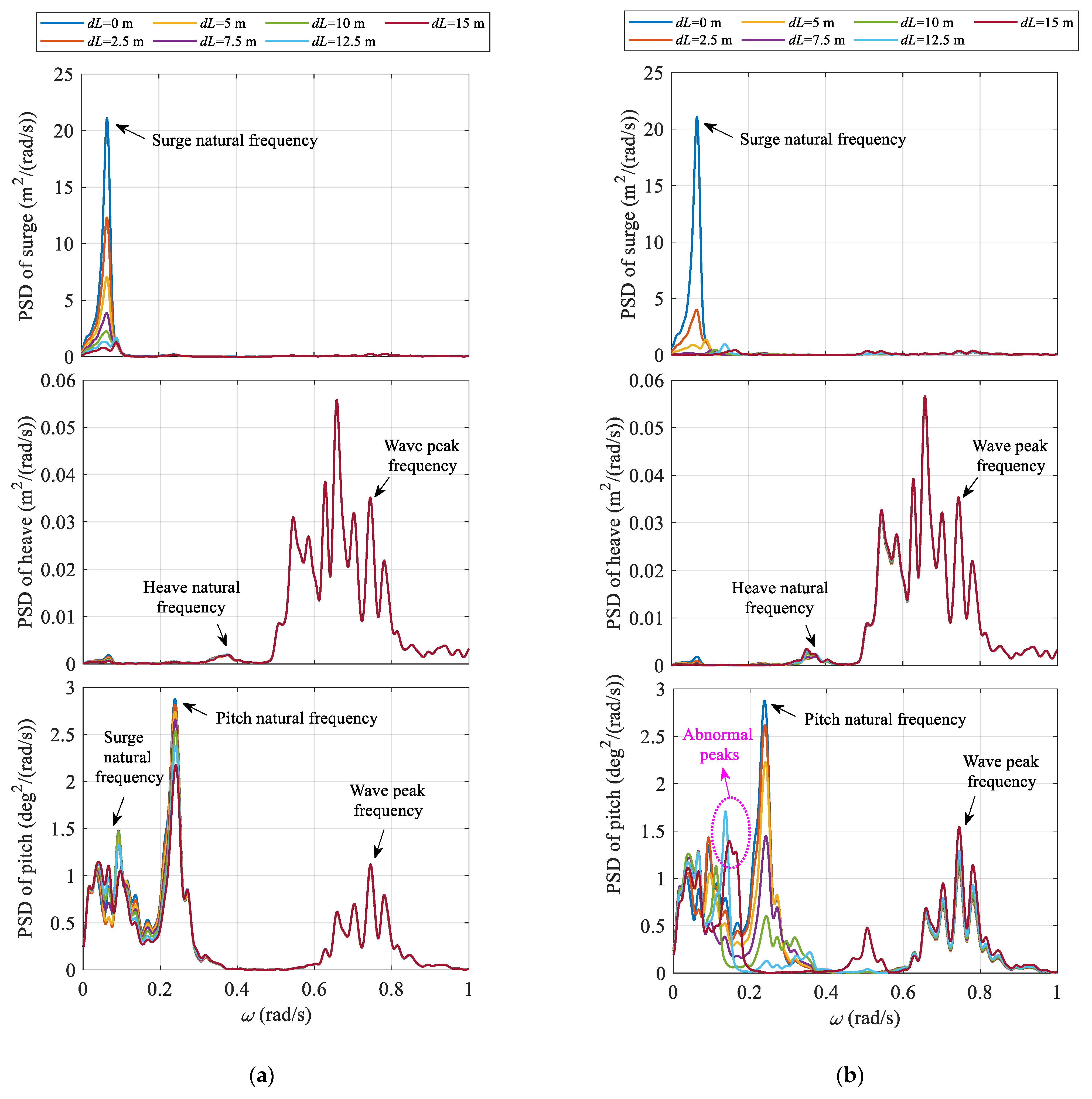
  • Under the rated conditions, pitch standard deviation could be reduced by 5.1% for the SMLC, and this number could reach 15.8% for the MMLC. This demonstrates that the proposed mooring control strategy is helpful to mitigate the floater pitch oscillations.
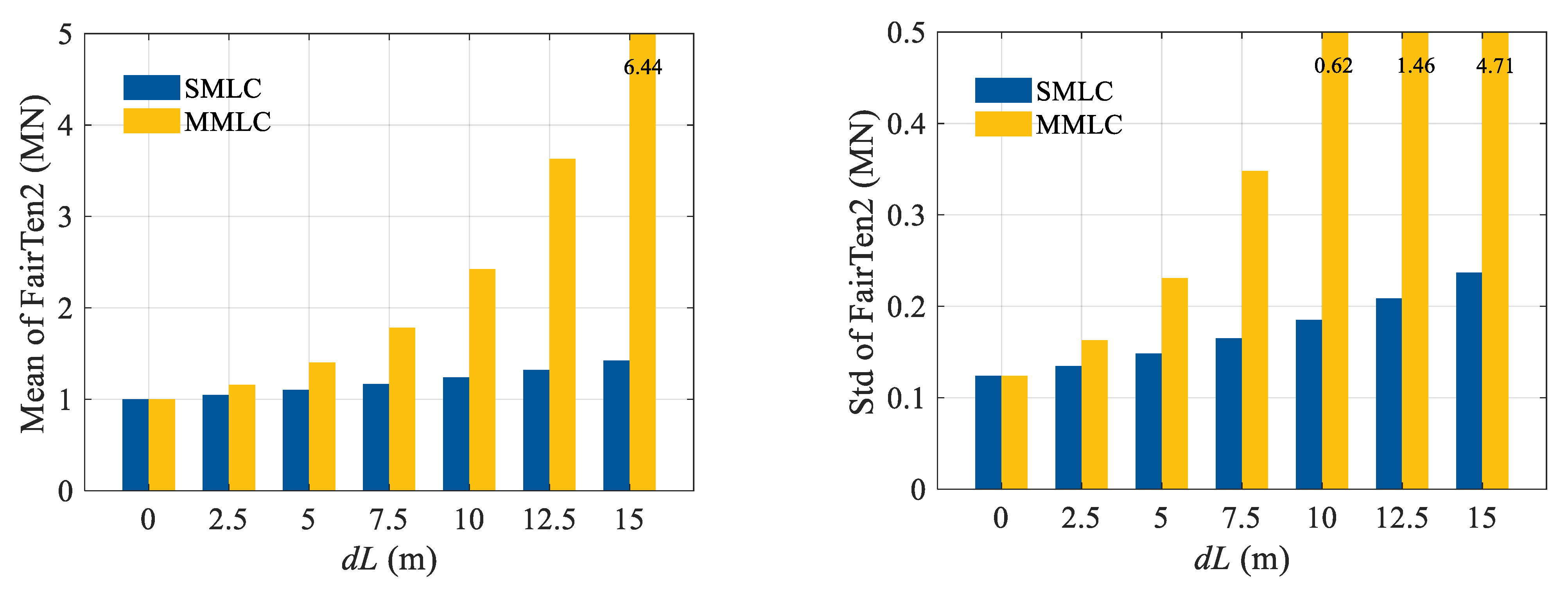
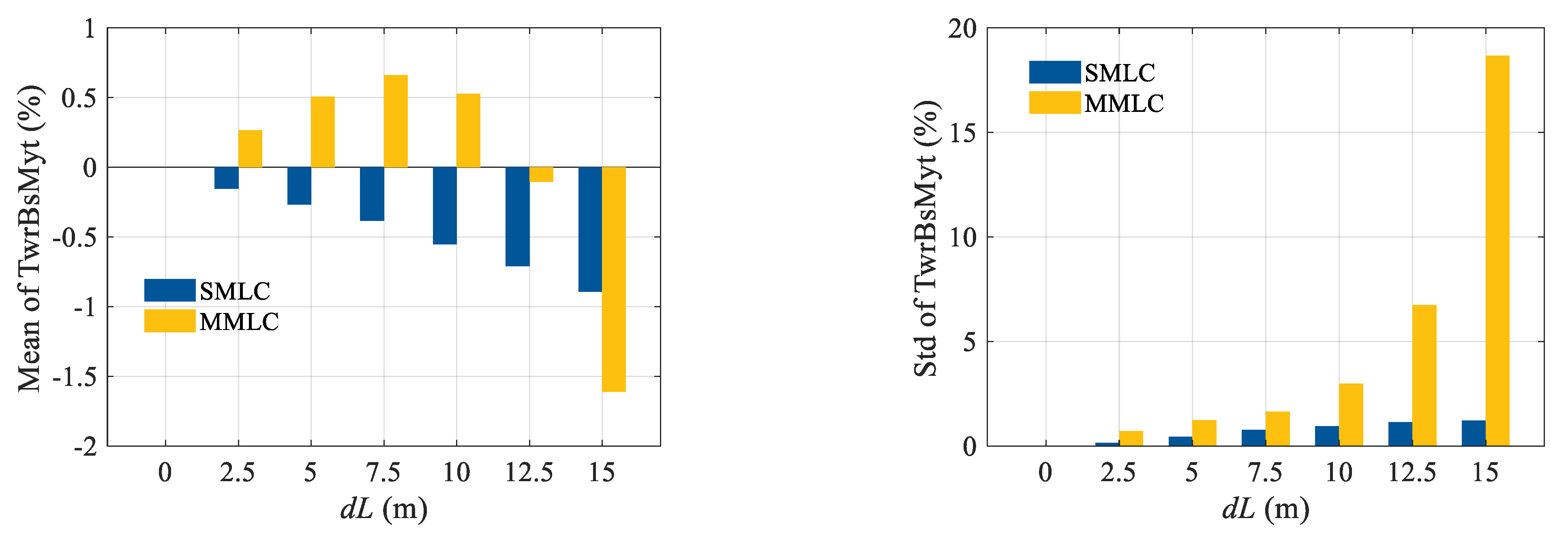
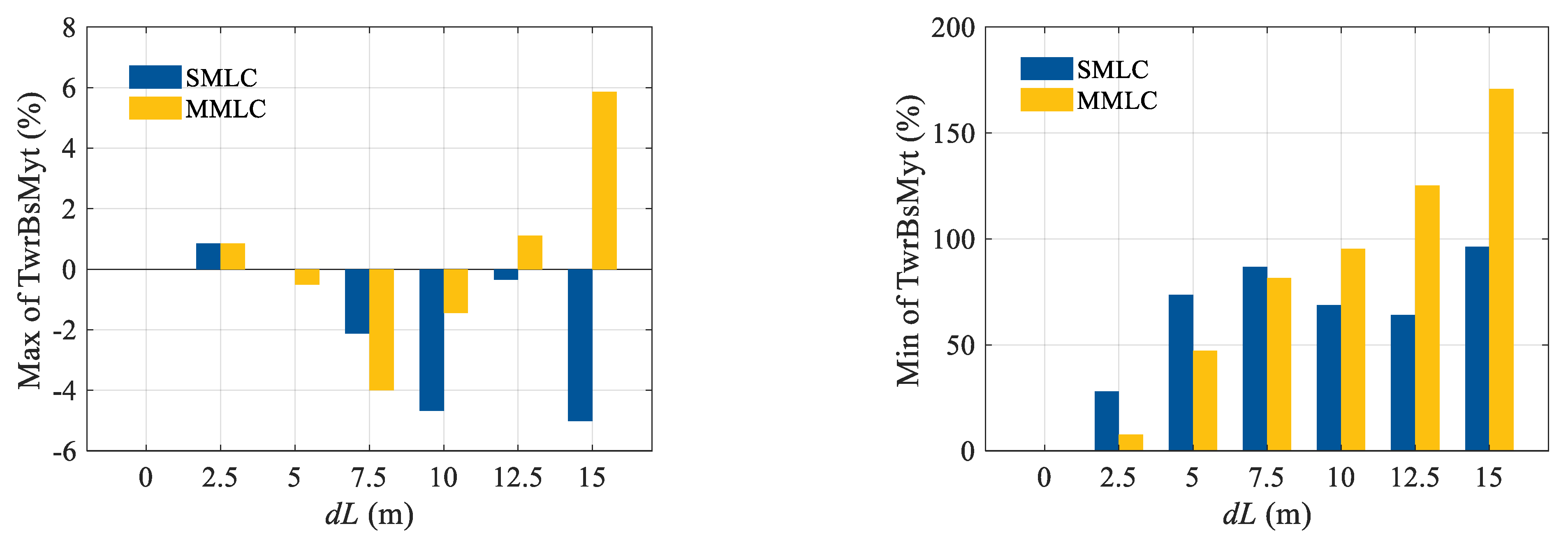
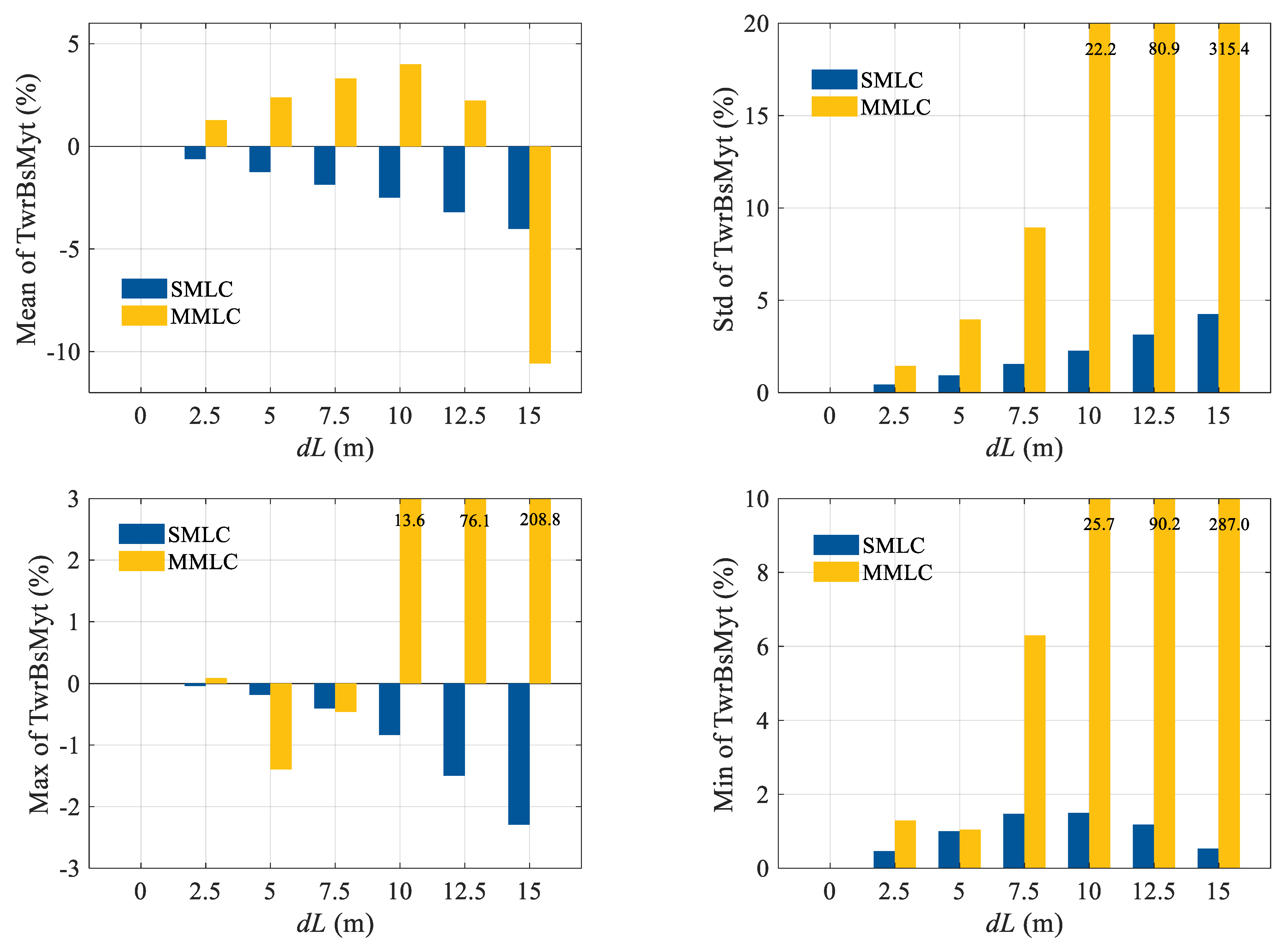
  • Under extreme conditions, pitch standard deviation is almost not changed for the SMLC, while the pitch standard deviation may be increased by over 100% for the MMLC when the mooring length is shortened by over 12.5 m, where the catenary mooring might become taut, which will cause large load variations, posing risks to mooring line breakages and anchor failures.

Author Contributions

Conceptualization, Y.Z. and Y.S.; funding acquisition, Y.Z. and Y.S.; investigation, X.Z.; methodology, J.C. and Y.Z.; writing—original draft, Y.Z.; writing—review and editing, Y.S., J.S. and R.L.; software, X.Z.; formal analysis, R.L. and Y.Z. All authors have read and agreed to the published version of the manuscript.

Funding

This research was funded by National Key Research and Development Program of China (Grant No. 2022YFB4201300), the Hainan Provincial Joint Project of Sanya Yazhou Bay Science and Technology City (Grant No. 2021CXLH0022), Zhejiang Provincial Natural Science Foundation (Grant No. LZ24E090001), and the Science Foundation of Donghai Laboratory (Grant No. DH-2022KF0308).

Institutional Review Board Statement

Not applicable.

Informed Consent Statement

Not applicable.

Data Availability Statement

The data that support the findings of this study are available within the article.

Acknowledgments

We would like to thank the editor and anonymous reviewers for their valuable comments and suggestions that greatly improved the quality of this paper.

Conflicts of Interest

Author Y.Z., J.C., R.L. were employed by the company Huaneng Clean Energy Research Institute, X.Z. was employed by the company Huaneng Hainan Clean Energy Co., Ltd. The remaining authors declare that the research was conducted in the absence of any commercial or financial relationships that could be construed as a potential conflict of interest.

References

  1. GWE Council. Global Offshore Wind Report 2022; GWEC: Brussels, Belgium, 2022. [Google Scholar]
  2. Barooni, M.; Ashuri, T.; Velioglu Sogut, D.; Wood, S.; Ghaderpour Taleghani, S. Floating offshore wind turbines: Current status and future prospects. Energies 2022, 16, 2. [Google Scholar] [CrossRef]
  3. Gu, Y.; Wang, P.; Rong, Z.; Wei, H.; Yang, S.; Zhang, K.; Tang, Z.; Han, T.; Si, Y. Vessel intrusion interception utilising unmanned surface vehicles for offshore wind farm asset protection. Ocean Eng. 2024, 299, 117395. [Google Scholar] [CrossRef]
  4. Barter, G.E.; Robertson, A.; Musial, W. A systems engineering vision for floating offshore wind cost optimization. Renew. Energy Focus 2020, 34, 1–16. [Google Scholar] [CrossRef]
  5. Jonkman, J.M. Dynamics Modeling and Loads Analysis of an Offshore Floating Wind Turbine. Ph.D. Thesis, Department of Aerospace Engineering Sciences, University of Colorado, Boulder, CO, USA, 2007. [Google Scholar]
  6. Jonkman, J.M.; Matha, D. Dynamics of offshore floating wind turbines—Analysis of three concepts. Wind Energy 2011, 14, 557–569. [Google Scholar] [CrossRef]
  7. Shi, W.; Zhang, L.; Karimirad, M.; Michailides, C.; Jiang, Z.; Li, X. Combined effects of aerodynamic and second-order hydrodynamic loads for floating wind turbines at different water depths. Appl. Ocean Res. 2023, 130, 103416. [Google Scholar] [CrossRef]
  8. Tsao, W.H.; Kees, C.E. An arbitrary Lagrangian-Eulerian regularized boundary integral method for nonlinear free-surface flows over complex topography and wave-structure interaction. Eng. Anal. Bound. Elem. 2023, 157, 326–341. [Google Scholar] [CrossRef]
  9. Subbulakshmi, A.; Verma, M.; Keerthana, M.; Sasmal, S.; Harikrishna, P.; Kapuria, S. Recent advances in experimental and numerical methods for dynamic analysis of floating offshore wind turbines—An integrated review. Renew. Sustain. Energy Rev. 2022, 164, 112525. [Google Scholar] [CrossRef]
  10. Patryniak, K.; Collu, M.; Coraddu, A. Multidisciplinary design analysis and optimisation frameworks for floating offshore wind turbines: State of the art. Ocean Eng. 2022, 251, 111002. [Google Scholar] [CrossRef]
  11. Shah, K.A.; Meng, F.; Li, Y.; Nagamune, R.; Zhou, Y.; Ren, Z.; Jiang, Z. A synthesis of feasible control methods for floating offshore wind turbine system dynamics. Renew. Sustain. Energy Rev. 2021, 151, 111525. [Google Scholar] [CrossRef]
  12. Sun, W.; Yuan, Y. Passivity based hierarchical multi-task tracking control for redundant manipulators with uncertainties. Automatica 2023, 155, 111159. [Google Scholar] [CrossRef]
  13. Wang, B.; Ma, Z.; Lai, S.; Zhao, L. Neural moving horizon estimation for robust flight control. IEEE Trans. Robot. 2023, 40, 639–659. [Google Scholar] [CrossRef]
  14. Zhuang, S.; Lei, D.; Yu, X.; Tong, M.; Lin, W.; Rodriguez-Andina, J.J.; Shi, Y.; Gao, H. Microinjection in biomedical applications: An effortless autonomous omnidirectional microinjection system. IEEE Ind. Electron. Mag. 2023. early access. [Google Scholar] [CrossRef]
  15. Sun, W.; Wang, X.; Zhang, C. A model-free control strategy for vehicle lateral stability with adaptive dynamic programming. IEEE Trans. Ind. Electron. 2019, 67, 10693–10701. [Google Scholar] [CrossRef]
  16. López-Queija, J.; Robles, E.; Jugo, J.; Alonso-Quesada, S. Review of control technologies for floating offshore wind turbines. Renew. Sustain. Energy Rev. 2022, 167, 112787. [Google Scholar] [CrossRef]
  17. Jonkman, J. Influence of control on the pitch damping of a floating wind turbine. In Proceedings of the 46th AIAA Aerospace Sciences Meeting and Exhibit, Reno, Nevada, 7–10 January 2008; p. 1306. [Google Scholar]
  18. Christiansen, S.; Knudsen, T.; Bak, T. Optimal control of a ballast-stabilized floating wind turbine. In Proceedings of the 2011 IEEE International Symposium on Computer-Aided Control System Design (CACSD), Denver, CO, USA, 28–30 September 2011; pp. 1214–1219. [Google Scholar]
  19. Namik, H.; Stol, K. Individual blade pitch control of floating offshore wind turbines. Wind Energy 2009, 13, 74–85. [Google Scholar] [CrossRef]
  20. Zhao, P.; Nagamune, R. Switching LPV control of a floating offshore wind turbine on a semi-submersible platform. In Proceedings of the 2019 IEEE 28th International Symposium on Industrial Electronics (ISIE), Vancouver, BC, Canada, 12–14 June 2019; pp. 664–669. [Google Scholar]
  21. Bakka, T.; Karimi, H.R. Mixed H2/H∞ control design for wind turbine system with pole placement constraints. In Proceedings of the 31st Chinese Control Conference, Hefei, China, 25–27 July 2012. [Google Scholar]
  22. Lackner, M.A.; Rotea, M.A. Structural control of floating wind turbines. Mechatronics 2011, 21, 704–719. [Google Scholar] [CrossRef]
  23. Tsao, W.H.; Chen, Y.C.; Kees, C.E.; Manuel, L. Response mitigation of floating platform by porous-media-tuned liquid dampers. J. Offshore Mech. Arct. Eng. 2023, 145, 051203. [Google Scholar] [CrossRef]
  24. Tong, X.; Zhao, X.; Karcanias, A. Passive vibration control of an offshore floating hydrostatic wind turbine model. Wind Energy 2018, 21, 697–714. [Google Scholar] [CrossRef]
  25. Roddier, D.; Cermelli, C.; Aubault, A.; Weinstein, A. WindFloat: A floating foundation for offshore wind turbines. J. Renew. Sustain. Energy 2010, 2, 033104. [Google Scholar] [CrossRef]
  26. Li, Y.; Wu, Z. Stabilization of floating offshore wind turbines by artificial muscle based active mooring line force control. In Proceedings of the 2016 American Control Conference (ACC), Boston, MA, USA, 6–8 July 2016; pp. 2277–2282. [Google Scholar]
  27. Benassai, G.; Campanile, A.; Piscopo, V.; Scamardella, A. Mooring control of semi-submersible structures for wind turbines. Procedia Eng. 2014, 70, 132–141. [Google Scholar] [CrossRef]
  28. Si, Y.; Chen, Z.; Zeng, W.; Sun, J.; Zhang, D.; Ma, X.; Qian, P. The influence of power-take-off control on the dynamic response and power output of combined semi-submersible floating wind turbine and point-absorber wave energy converters. Ocean Eng. 2021, 227, 108835. [Google Scholar] [CrossRef]
  29. Zhang, D.; Chen, Z.; Liu, X.; Sun, J.; Yu, H.; Zeng, W.; Ying, Y.; Sun, Y.; Cui, L.; Yang, S.; et al. A coupled numerical framework for hybrid floating offshore wind turbine and oscillating water column wave energy converters. Energy Convers. Manag. 2022, 267, 115933. [Google Scholar] [CrossRef]
  30. Si, Y.; Karimi, H.R.; Gao, H. Modelling and optimization of a passive structural control design for a spar-type floating wind turbine. Eng. Struct. 2014, 69, 168–182. [Google Scholar] [CrossRef]
  31. Zuo, H.; Bi, K.; Hao, H. A state-of-the-art review on the vibration mitigation of wind turbines. Renew. Sustain. Energy Rev. 2020, 121, 109710. [Google Scholar] [CrossRef]
  32. Stockhouse, D.; Phadnis, M.; Grant, E.; Johnson, K.; Damiani, R.; Pao, L. Control of a floating wind turbine on a novel actuated platform. In Proceedings of the 2022 American Control Conference (ACC), Atlanta, GA, USA, 8–10 June 2022; pp. 3532–3537. [Google Scholar]
  33. Grant, E.; Johnson, K.; Damiani, R.; Phadnis, M.; Pao, L. Buoyancy can ballast control for increased power generation of a floating offshore wind turbine with a light-weight semi-submersible platform. Appl. Energy 2023, 330, 120287. [Google Scholar] [CrossRef]
  34. Wu, Z.; Li, Y. Platform stabilization of floating offshore wind turbines by artificial muscle based active mooring line force control. IEEE/ASME Trans. Mechatron. 2020, 25, 2765–2776. [Google Scholar] [CrossRef]
  35. Wu, Z.; Li, Y. Hybrid model predictive control of floating offshore wind turbines with artificial muscle actuated mooring lines. J. Dyn. Syst. Meas. Control 2022, 144, 051003. [Google Scholar] [CrossRef]
  36. Aase, Ø. Modeling and Control of Catenary Mooring Systems for Vessels, Oil Rigs, and Barges. Master’s Thesis, NTNU, Trondheim, Norway, 2018. [Google Scholar]
  37. Dinius, J.D.; Damiani, R.; Johnson, K.; Grant, E.; Pao, L.Y.; Phadnis, M. Control actuation options for the SpiderFLOAT floating offshore wind substructure. In Proceedings of the 2022 AIAA SCITECH Forum, San Diego, CA, USA, 3–7 January 2022; p. 2295. [Google Scholar]
  38. Suzuki, H.; Shiohara, H.; Schnepf, A.; Houtani, H.; Carmo, L.H.; Hirabayashi, S.; Haneda, K.; Chujo, T.; Nihei, Y.; Malta, E.B.; et al. Wave and wind responses of a very-light FOWT with guy-wired-supported tower: Numerical and experimental studies. J. Mar. Sci. Eng. 2020, 8, 841. [Google Scholar] [CrossRef]
  39. Nagumo, T.; Suzuki, H.; Houtani, H.; Takaoka, M.; Gonçalves, R.T. Experimental and numerical studies on regular wave responses of a very-light FOWT with a guy-wired-supported tower: Effects of wave height, wave direction, and mooring line configuration. Ocean Eng. 2024, 295, 116844. [Google Scholar] [CrossRef]
  40. Available online: https://github.com/OpenFAST/openfast (accessed on 1 March 2024).
  41. Robertson, A.; Jonkman, J.; Masciola, M.; Song, H.; Goupee, A.; Coulling, A.; Luan, C. Definition of the Semisubmersible Floating System for Phase II of OC4; NREL/TP-5000-60601; National Renewable Energy Lab (NREL): Golden, CO, USA, 2014. [Google Scholar]
  42. Jonkman, J.; Butterfield, S.; Musial, W.; Scott, G. Definition of a 5-MW Reference Wind Turbine for Offshore System Development; National Renewable Energy Lab (NREL): Golden, CO, USA, 2009. [Google Scholar]
  43. Jonkman, B.; Bhul, M.L. Turbsim Users Guide. Tech Rep. NREL/EL-500-36970; National Renewable Energy Laboratory: Golden, CO, USA, 2005. [Google Scholar]
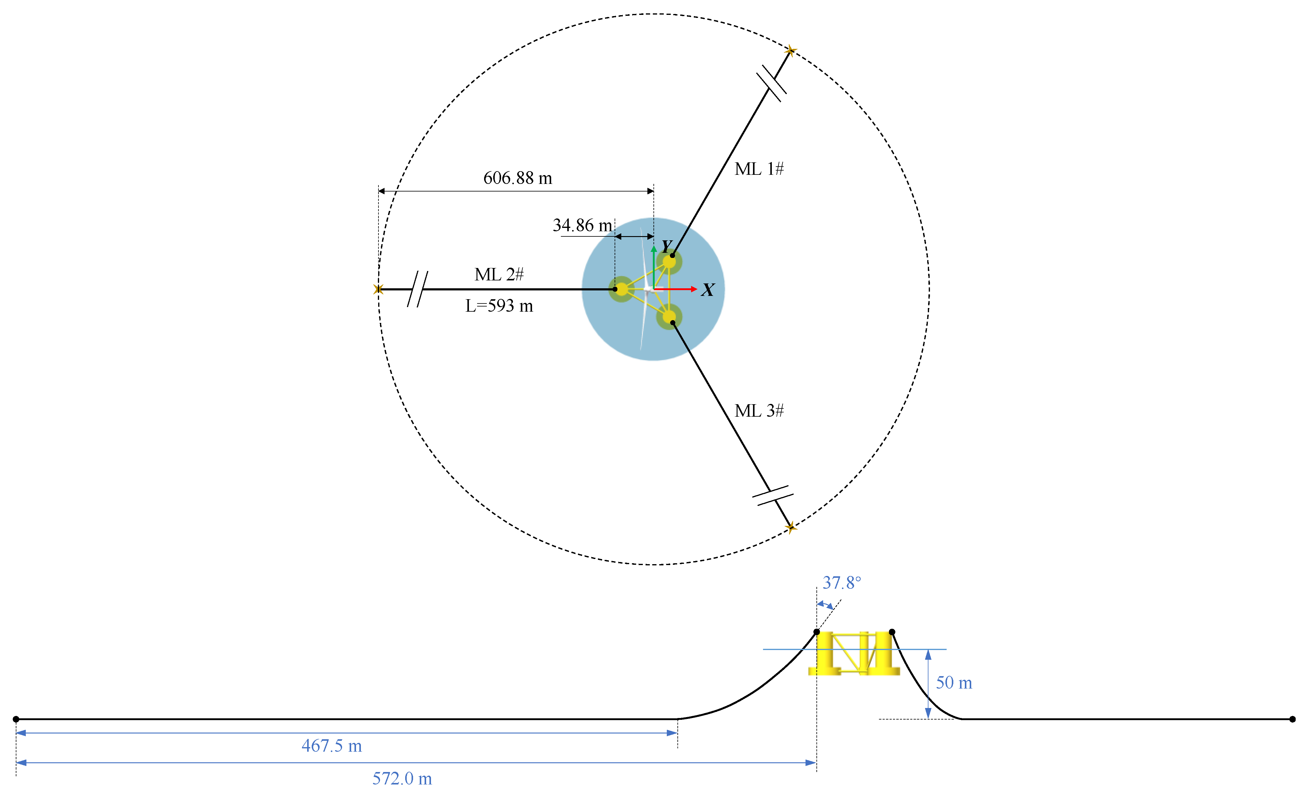
Figure 1. Illustration of the catenary mooring line control process.
Jmse 12 00628 g001
Figure 2. Geometry of the OC4-DeepCwind FOWT.
Jmse 12 00628 g002
Figure 3. Modified mooring system configuration (top and side view) for NREL OC4 DeepCwind FOWT in 50 m water depth.
Jmse 12 00628 g003
Figure 4. Time-series and power spectrum of wind speed and wave height under rated condition.
Jmse 12 00628 g004
Figure 5. Time-series of the wind speed and wave height under extreme conditions.
Jmse 12 00628 g005
Figure 6. Modelling of a dynamic mooring line in OpenFAST.
Jmse 12 00628 g006
Figure 7. RAO results of different mooring control designs.
Jmse 12 00628 g007
Figure 8. Time-series of platform displacement, tower-bottom bending moment, and mooring tensions with different mooring length alterations (SMLC, rated).
Jmse 12 00628 g008
Figure 9. Time-series of platform displacement, tower-bottom bending moment, and mooring tensions with different mooring length alterations (MMLC, rated).
Jmse 12 00628 g009
Figure 10. Statistical results of platform surge with different mooring control configurations (rated).
Jmse 12 00628 g010
Figure 11. Statistical results of platform heave with different mooring control configurations (rated).
Jmse 12 00628 g011
Figure 12. Statistical results of platform pitch with different mooring control configurations (rated).
Jmse 12 00628 g012
Figure 13. Power spectrum densities of platform motion with different mooring control configurations (rated). (a) SMLC (b)MMLC.
Jmse 12 00628 g013
Figure 14. Statistical results of tower-bottom fore-aft bending moments (TwrBsMyt) reduction with different mooring control configurations (rated) (+increment, −decrement).
Jmse 12 00628 g014aJmse 12 00628 g014b
Figure 15. Statistical results of ML2 tensions (FairTen2) with different mooring control configurations (rated).
Jmse 12 00628 g015
Figure 16. Time-series of platform displacement, tower-bottom bending moment, and mooring tensions with different mooring length alterations (SMLC, parked).
Jmse 12 00628 g016
Figure 17. Time-series of platform displacement, tower-bottom bending moment, and mooring tensions with different mooring length alterations (MMLC, parked).
Jmse 12 00628 g017
Figure 18. Statistical results of platform surge with different mooring control configurations (parked).
Jmse 12 00628 g018
Figure 19. Statistical results of platform heave with different mooring control configurations (parked).
Jmse 12 00628 g019aJmse 12 00628 g019b
Figure 20. Statistical results of platform pitch with different mooring control configurations (parked).
Jmse 12 00628 g020
Figure 21. Power spectrum densities of platform motion with different mooring control configurations (parked). (a) SMLC (b)MMLC.
Jmse 12 00628 g021aJmse 12 00628 g021b
Figure 22. Statistical results of tower-bottom fore-aft bending moments (TwrBsMyt) reduction with different mooring control configurations (parked) (+increment, −decrement).
Jmse 12 00628 g022
Figure 23. Statistical results of ML2 tensions (FairTen2) with different mooring control configurations (parked).
Jmse 12 00628 g023aJmse 12 00628 g023b
Table 1. Primary mooring parameters.
Mooring Line No.Anchor Location (m)Fair-Lead Location (m)Length (m)Diameter (m)Fairlead Initial Angle
(deg)
Touchdown Length
(m)
Pretension
(MN)
Mass Density (kg/m)Equivalent Extensional Stiffness (N)
ML 1(303.43, 525.56, −50)(17.43, 30.20, 12)5930.1537.8467.50.791511.73 × 109
ML 2(−606.8676, 0, −50)(−34.8682, 0, 12)5930.1537.8467.50.791511.73 × 109
ML 3(303.43, −525.56, −50)(17.43, 30.20, 12)5930.1537.8467.50.791511.73 × 109
Table 2. Environmental conditions.
Environmental
Condition
Mean Wind Speed (m/s)Turbulence Intensity (%)Significant Wave Height (m)Peak Wave Period (s)Jonswap
γ Factor
SMLC
(m)
MMLC
(m)
Rated condition11.4153.88.32.350:2.5:150:2.5:15
Extreme condition35810.314.12.020:2.5:150:2.5:15
Disclaimer/Publisher’s Note: The statements, opinions and data contained in all publications are solely those of the individual author(s) and contributor(s) and not of MDPI and/or the editor(s). MDPI and/or the editor(s) disclaim responsibility for any injury to people or property resulting from any ideas, methods, instructions or products referred to in the content.

