Article

Study on the Adsorption Performance of a Vortex Suction Cup under Varying Diameters of Underwater Structure Tubes

1
College of Mechanical and Electrical Engineering, Harbin Engineering University, Harbin 150001, China
2
National Key Laboratory of Intelligent Ocean Navigation Technology, Harbin Engineering University, Harbin 150001, China
3
Offshore Oil Engineering Co., Ltd., Tianjin 300461, China
*
Author to whom correspondence should be addressed.
J. Mar. Sci. Eng. 2024, 12(4), 662; https://doi.org/10.3390/jmse12040662
Submission received: 21 March 2024 / Revised: 13 April 2024 / Accepted: 15 April 2024 / Published: 17 April 2024
(This article belongs to the Section Ocean Engineering)

Abstract

:
In certain precision work scenarios, underwater robots require the ability to adhere to surfaces in order to perform tasks effectively. An efficient and stable suction device plays a pivotal role in the functionality of such underwater robots. The vortex suction cup, distinguished by its uncomplicated design, high suction efficiency, and capability for non-contact adhesion, holds significant promise for integration into underwater robotic systems. This paper presents a novel design for a vortex suction cup and investigates its suction force and torque when encountering surfaces with varying curvature radii using Computational Fluid Dynamics (CFD) simulations and experimental testing. These findings offer valuable insights for the development of robots capable of adapting to underwater structures of different dimensions. Results from both experiments and simulations indicate that reducing the curvature radius of the adhered surface results in a decrease in suction force and an increase in torque exerted on the suction cup. As the adhered surface transitions from flat to a curvature radius of 150 mm, the adhesion force of our proposed vortex suction cup decreases by approximately 10%, while the torque increases by approximately 20% to 30%. Consequently, the adhesion efficiency of the suction cup decreases by about 25% to 30%.

1. Introduction

In recent years, the demand for inspecting, cleaning, and maintaining various underwater structures has surged, resulting in the creation of various underwater examination robots [1,2,3,4,5,6,7] designed to undertake hazardous tasks in place of humans. In these applications, tasks have become increasingly intricate, necessitating higher levels of mobility and stability in robots. Often, robots must securely adhere to working surfaces to execute detection tasks effectively. Hence, one of the most challenging aspects of designing such underwater vehicles is devising suitable adhesion mechanisms to ensure reliable wall attachment without compromising mobility.
Various technologies have been employed for underwater adhesion, including magnetic [8,9,10], vacuum [11,12], propeller [13,14,15], and Bernoulli negative pressure adsorption [3,6,16,17]. However, each method has its drawbacks. For example, magnetic adhesion is limited to ferromagnetic materials, which are uncommon in nuclear power pools, predominantly composed of weak magnetic materials. Although most offshore structures are ferromagnetic, their underwater sections are typically encased in thick anti-corrosion layers, reducing adhesion effectiveness. Vacuum suction cups require wall contact to maintain vacuum seals, causing friction that impedes robot movement, particularly on uneven surfaces. Propeller and Bernoulli negative pressure adsorption, while not constrained by surface material or flatness, demand substantial power and yield low adhesion efficiency.
Vortex suction cups have made headway in addressing these challenges. These devices generate negative pressure through high-speed vortex rotation within a chamber. Vortex suction cups retain high-speed fluid within the chamber, limiting energy exchange with external fluid. Compared to thruster reverse thrust and Bernoulli negative pressure adsorption, vortex adhesion requires less power to achieve greater adhesion force. Li et al. [18] concluded through experiments that pneumatic vortex suction cups require less flow and air power loss than pneumatic Bernoulli suction cups. Li et al. [19,20,21] demonstrated that pneumatic vortex suction cups require less airflow and experience lower air power loss than traditional pneumatic suction cups. The authors Zhu et al. [22] designed an underwater vortex suction cup powered by electricity, and studied the correlation between impeller speed, adsorption gap, and adhesion force. Zhao et al. [23] devised a method involving the utilization of a vortex suction cup that introduces high-pressure water tangentially to induce rapid rotation of the chamber, thereby generating adhesion force, successfully deploying it in underwater robots. Fan et al. [24] investigated the impact of various factors, including the number of impeller blades, cup shell configuration, adsorption gap, and impeller velocity, on the adhesion capability of suction cups.
However, previous research on vortex suction cup adhesion surfaces has assumed flat surfaces, neglecting the impact of varying surface curvature. When the adsorption tube diameter is small, the suction cup adhesion gap can vary significantly. Extensive research indicates a strong correlation between vortex suction cup adhesion performance and adhesion gap. Thus, changes in adhesion surface curvature can significantly affect suction cup adhesion performance. This paper aims to explore the influence of adhesion surface curvature on vortex suction cup adhesion performance through CFD dynamic simulation and experimental validation, providing essential insights for underwater robots operating on structures with different pipe diameters.
This paper presents a motor-driven vortex suction cup design, evaluating its adhesion characteristics under diverse conditions using CFD methods. Flow field analysis encompasses velocity and pressure distribution. An experimental platform quantifies adhesion characteristics, including force and torque parameters, under varying curvature radii and speeds in underwater environments. Power consumption under different adhesion surface curvatures is derived through torque, speed, and power mathematical relationships. An efficiency parameter, η = F/P, where 1 W power yields the adhesion force, torque, and other experimental and simulation-derived information, is constructed. Analysis of scroll suction adhesion force, torque, and efficiency under varying adhesion surface curvature quantifies the curvature’s impact on scroll suction.
The following sections are organized in the following manner: Section 2 delineates design considerations for vortex-based suction, focusing on cup curvature radius and adhesion surface influence on the adhesion gap. Section 3 presents Computational Fluid Dynamics (CFD) techniques for analyzing the flow and pressure distribution of vortex suction cups. Section 4 analyzes and compares adhesion properties of surfaces with different curvatures through experimental verification. Section 5 summarizes the main findings and proposes further research avenues.

2. Vortex Suction Cup and Adsorption Gap

2.1. The Proposed Vortex Suction Cup

The proposed device for vortex suction is shown in Figure 1. A motor serves as the driving source, a impeller generates eddy currents, and a cup shell creates negative pressure. An encoder measures the motor speed and provides feedback to the motor driver. The cylindrical cavity cup shell has an upper surface that is sealed and firmly attached to the motor. The impeller, which has twelve blades symmetrically distributed perpendicular to the chamber’s upper surface, is securely connected to the motor shaft. Each blade has an angle φ at its outermost point. Eddy currents are created when the impeller rotates, propelled by the motor, and create negative pressure gradients within the chamber. As a result, there is lower pressure on the inner surface of the cup shell chamber than on its outer surface, leading to suction force acting on top of it. The magnitude of this suction force increases with greater negative pressure.
Figure 2 illustrates the structural size diagram of the scroll suction cup utilized in this investigation. In the frontal perspective, the vertical distance separating the impeller and the surface of the chamber is referred to as H1. The height of the impeller is denoted as H, while a deliberate gap labeled H2 exists between the impeller and the lower surface of the chamber to prevent any potential contact or abrasion between them. In terms of an overhead view, there is a folding angle φ present at the outer end of the impeller, with specified dimensions including the impeller radius r1, inner cavity radius r2, outer cavity radius r3, and shell radius r4. Table 1 provides a detailed list of these specific dimensions.

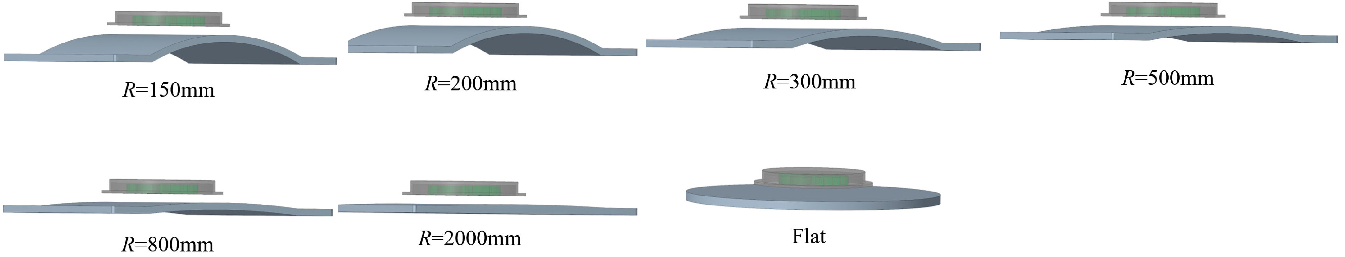
2.2. The Adsorption Gap of Vortex Suction Cup

Fan et al. [22,24] indicate that the adsorption force generated by the vortex suction cup varies with the distance between the wall and the suction cup. Consequently, this section will explore the correlation between the adhesion gap of the suction cup and the curvature radius of the wall.
In practical work, underwater structures often have uneven surfaces due to obstacles such as marine organisms. To ensure adequate maneuverability for underwater robots, the vortex suction cup is positioned at a minimum vertical distance of h = 10 mm from the wall, as depicted in Figure 3. The suction cup adheres to a surface with a curvature radius of R, with the narrowest and widest gaps defined as h and hmax, respectively. This setting establishes the following relationship:
h m a x = R R 2 r 4 2 + h
Based on Equation (1), we investigated the relationship between the curvature radius R of different underwater structures’ surfaces and the maximum adsorption gap hmax. The numerical results are illustrated in Figure 4. It is observed that as the radius of wall curvature decreases, the maximum adsorption gap hmax of the vortex suction cup increases. Specifically, for wall curvature radii less than 1000 mm, hmax exhibits a pronounced variation. In contrast, when the wall curvature radius exceeds 1000 mm, the change in the maximum adsorption gap becomes more gradual, with a variation of less than 2.5 mm. Consequently, for subsequent simulation and verification experiments, it is advisable to design a greater number of experimental groups for radii below 1000 mm, whereas fewer groups suffice for wall radii exceeding 1000 mm.

3. Computational Fluid Dynamics (CFD) Simulation

Through theoretical analysis of the suction mechanism in vortex suction cups, it has been established that adhesion force arises from high-speed rotation within the chamber. To examine the influence of various wall curvature radii on adhesion performance, we used a Computational Fluid Dynamics (CFD) simulation approach to analyze adhesion force and torque when encountering walls with diverse curvature radii. Extensive investigations indicated that numerical simulations conducted with Star CCM+ 2310 (18.06.006-R8) software align more closely with real-world scenarios, justifying our selection for these simulations.

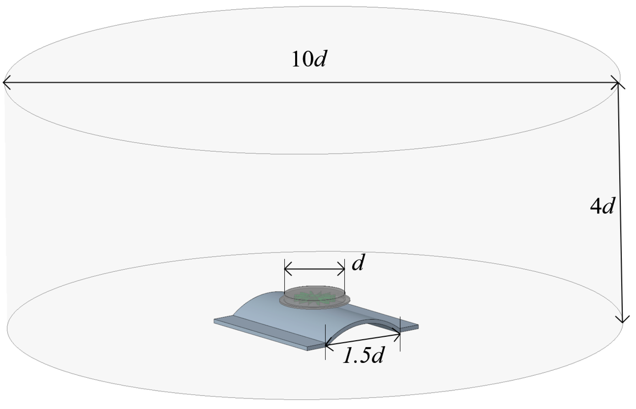
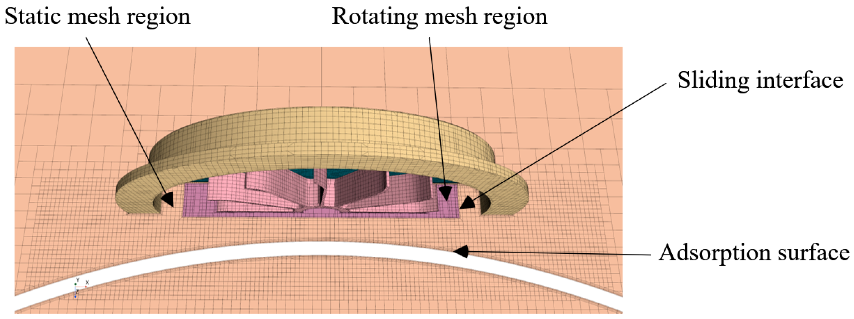
3.1. Simulation Setup

In CFD simulations, the vortex suction cup was simplified as a cup shell and an impeller. Different curvature radii fixed plates were used as adsorption surfaces to generate suction force, with the closest distance between the suction cup and the adsorption surface being h = 10 mm, as shown in Figure 5. A total of six sets of models with different curvature radii and one set of flat models were used for CFD simulations. After importing the models into the computational domain, different rotational speeds (n = 1000, 1500, 2000, 2500 r/min) were set for each model’s impeller to investigate the effect of rotational speed on adsorption performance. In order to reduce cell quantity and save computational resources without compromising accuracy, only a portion of wall surfaces (chord length = 1.5 d) were simulated during the simulation process. The computational domain of the simulation is shown in Figure 6. The entire device was placed in a cylindrical flow field with a cylinder diameter of 10 d and height of 4 d, where d denotes the largest dimension of the suction cup enclosure.
For the simulation of turbulence, the k-ε model was chosen. The k-ε model stands as the most commonly used turbulence model in Computational Fluid Dynamics (CFD). It boasts superior computational efficiency compared to Reynolds Averaged Navier–Stokes (RANS) and Large Eddy Simulation (LES) models, enabling the simulation of large flow fields within shorter time frames. Moreover, this model finds extensive application in engineering, offering calculation results that closely align with real-world scenarios [25,26,27]. Hexahedral mesh was employed for grid division, as depicted in Figure 7. Within the rotating region of the impeller, a rotational domain was defined. The rotational domain was partitioned using a dynamic grid technique to accurately simulate impeller rotation. Other fluid regions were designated as static domains, with an interface established between the rotating and static domains for data transmission and interpolation. In order to improve the accuracy of the solution, an orthogonal prism layer grid was generated at the interface of the rotating domain, with areas featuring complex flow fields refined, such as the blade and suction cup gap. A specific rotational speed was imposed on the impeller as the moving wall boundary condition. The surface of the suction shell, fixed walls, and the side and bottom of the cylinder basin were set as non-slip wall conditions, while the upper surface of the water was defined as the pressure outlet boundary condition.
The simulation time step was calculated according to the following formula:
Δ T = 1 n 60 360
Among them, n represents the rotational speed of the impeller, and at n = 2500 rpm, Δ T = 6.67 × 10 5   (s). In order to verify that grid partitioning has no influence on experimental results, it is necessary to conduct a grid independence verification. Three different sizes of cells were selected for simulation, and the results are shown in Table 2 (R = 150 mm, h = 10 mm, n = 2500 r/min). After conducting simulations, it was found that the medium-sized and fine-sized mesh systems produced nearly identical results. Therefore, to ensure accuracy while conserving computational resources, we have chosen to use the medium-sized mesh system for future simulations.

3.2. Simulation Flow Field Observation

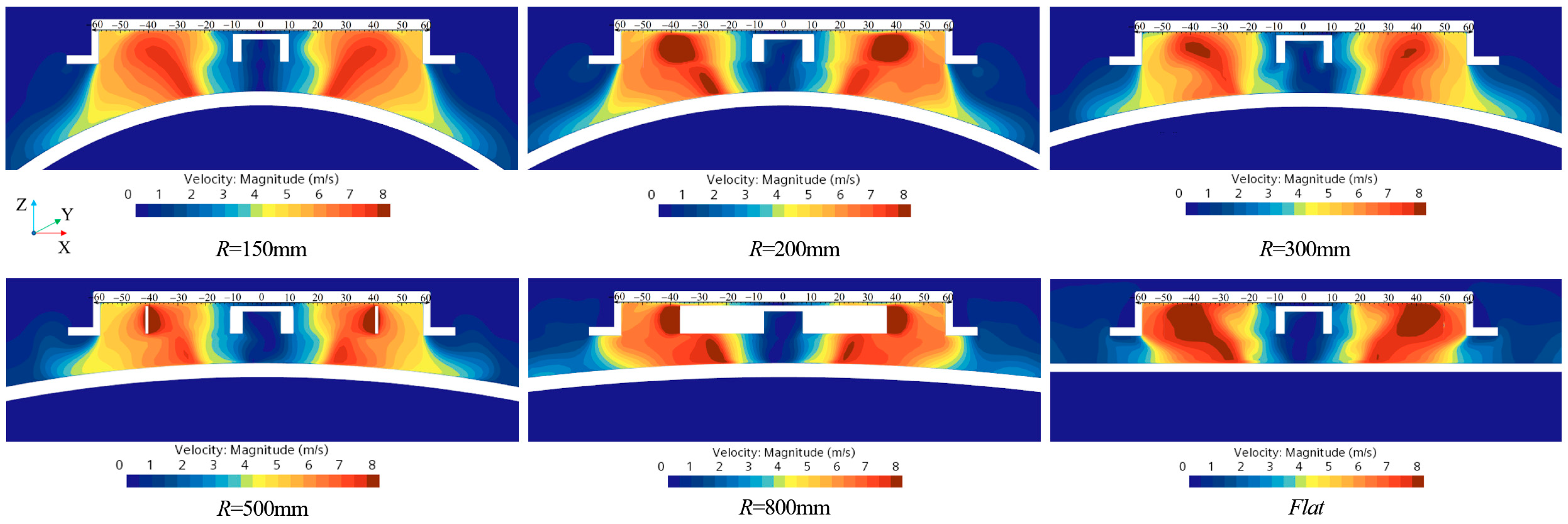
3.2.1. Flow Velocity Distribution

The velocity distribution of the flow in the XZ plane of the suction cup under different adsorption surface curvature radii is shown in Figure 8 (h = 10 mm, n = 2000 r/min). Changes in the adsorption gap resulting from variations in the curvature of the adsorption surface are clearly visible in the XZ plane, along with the distribution of fluid within these gaps. Figure 8 illustrates that the distribution pattern of internal velocities within the suction cup remains essentially consistent for different radii of adsorption surface curvature, with velocities proportional to the impeller’s radius within a certain range. Additionally, it is evident that the high-speed rotating vortices inside the suction cup chamber induce fluid rotation beneath it. As the curvature radius decreases, the maximum adsorption gap, hmax, gradually increases, providing a larger channel for velocity and energy exchange between internal and external fluids. More fluid beneath the suction cup is also driven into rotation.

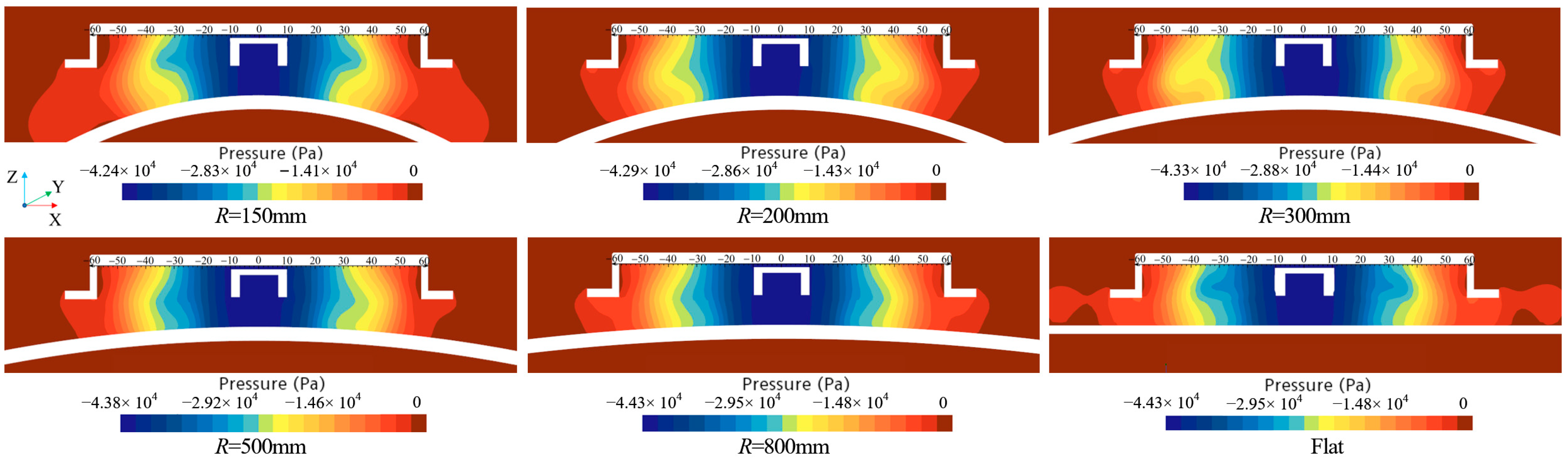
3.2.2. Pressure Distribution

Figure 9 illustrates the pressure distribution in the XZ plane of a suction cup under different adsorption surface curvature radii (h = 10 mm, n = 2000 r/min). It can be observed that the internal pressure distribution within the suction cup remains relatively consistent without any adsorption surface curvature. The high-speed rotating vortex creates a negative pressure region inside the suction cup, with an increasing absolute value of negative pressure as it approaches the center. As the radius of the curvature decreases, both the area and maximum absolute value of this negative pressure region gradually decrease. Since the adhesion force generated by vortex suction cups relies on the difference between external and internal surface pressures on their shell, adhesion force also diminishes with a decreasing radius of curvature.

4. Experimental Validation and Discussion

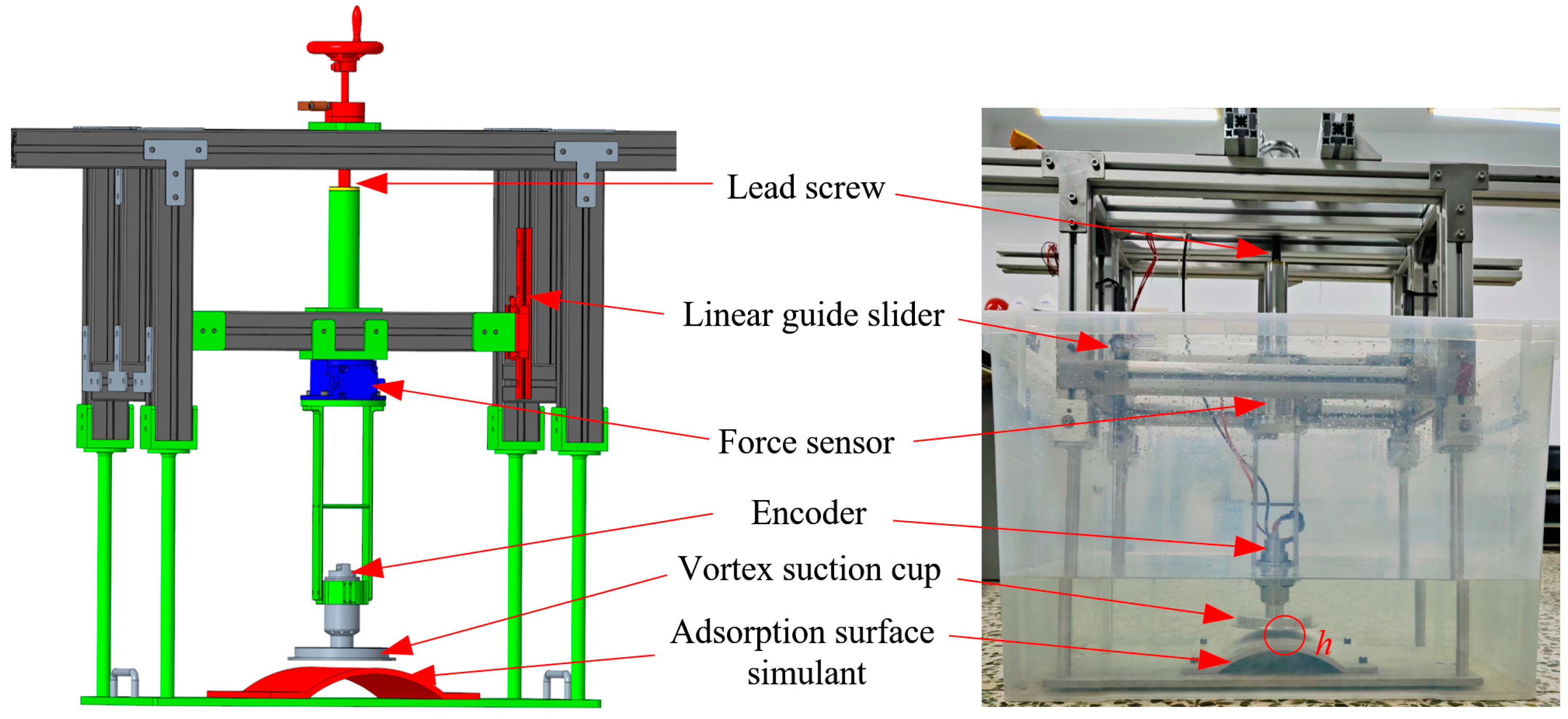
4.1. Setup for the Experiment

The adsorption performance of the suction cup was tested using a specially designed testing platform, as depicted in Figure 10. This platform primarily comprised a framework housing all testing apparatus. A gap adjustment mechanism utilized the combination of a screw nut and linear guide to adjust the distance between the suction cup and the adsorption surface. Rotating the screw enabled the vertical movement of the suction cup, facilitating accurate distance adjustment from the wall. A force sensor (GAMMA IP68 IS-130-10, AIT-IA, Apex, NC, USA) was used to measure the suction force and output torque of the suction cup. The Z-axis force measuring range spanned from 0 to 400 N, with a force resolution of 0.1 N. Additionally, the torque measuring range was 10 Nm, accompanied by a torque resolution of 0.0025 Nm. The simulated adsorption surface body was affixed to the bottom plate of the frame using bolts and then aligned with the suction cup using the gap adjustment mechanism (The simulated physical photographs of objects with different diameters are shown in Supplementary Material Figure S1). Upon completion of adjustments, the locking device was engaged to secure it. At this stage, the connection between the suction cup and the framework became rigid, and the suction force generated became the internal force applied within the testing platform. After adjusting the gap and tightening the screw rod, the entire apparatus could be considered as rigidly connected. At this point, it was equivalent to the force sensor being fixed to the frame, and the suction force generated by the vortex suction cup would cause the strain gauge of the force sensor to experience tensile strain. By measuring the magnitude of this tensile strain, the force sensor could determine the suction force of the vortex suction cup. The measurement principle for the torque of the vortex suction cup is analogous.
Due to limitations imposed by our current experimental apparatus and for operational convenience, we are currently conducting our experiments in a water tank made of PVC plastic with limited dimensions. The tank has measurements of 70 cm length, 45 cm width, and 50 cm height, with the water depth set at 30 cm. During the experiment, it was evident that high rotational speeds induced vortex formation in the water tank. However, their flow velocity remained relatively low compared to the high-speed vortices within the suction cup and can be deemed negligible. Consequently, they exerted minimal influence on the experiment results of the suction cup.

4.2. Results and Discussions

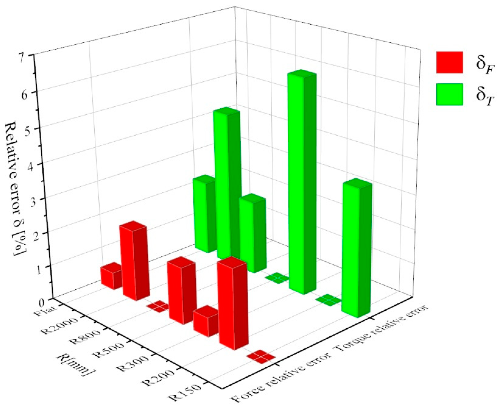
4.2.1. Comparison of Experimental and Simulation Results

The primary objective of this section is to assess the accuracy of Computational Fluid Dynamics (CFD) simulation methods by evaluating the errors between simulated and experimental data. The relative error between simulation and experiment is compared by examining the simulation and experimental data of the vortex suction cup rotating at a speed of n = 2000 r/min as an example. Table 3 provides the data for simulation and experimental comparison.
Assuming the experimental results as accurate, the simulation’s force relative error (δF) can be determined using the following calculation:
δ F = | F sim F exp | F exp × 100 %
In this context, Fsim represents the simulation force and Fexp represents the experimental force. The torque relative error δT can be calculated using Equation (3) by substituting Tsim and Texp, which represent the simulated torque and experimental torque, respectively. The results associated with each data point are depicted in Figure 11. The force and torque exhibit maximum relative errors of 2.29% and 6.25%, respectively, while the adsorption force and torque demonstrate average relative errors of 1.02% and 2.70%. Due to the limitation of the size of the experimental water tank, we observed that the external water flow around the suction cup was affected by high-speed vortices inside the suction cup, resulting in slow movement within the water tank. In simulation, the volume of the simulated domain is much larger than the actual volume of the water tank, which may be one potential reason for discrepancies between experimental and simulated results. Overall, these errors fall within an acceptable range, indicating that the CFD simulation adequately represents this complex problem.

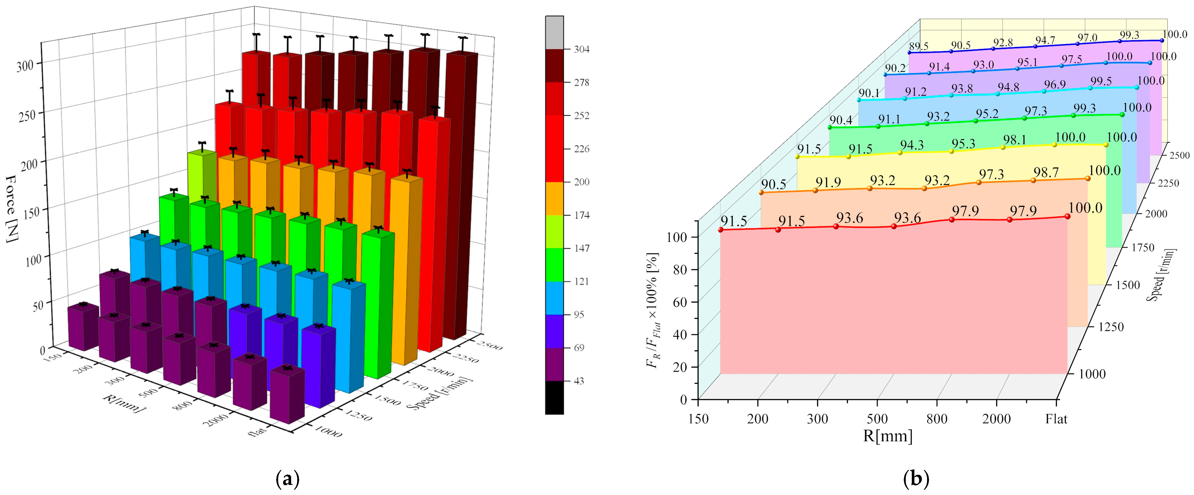
4.2.2. Adsorption Forces

Figure 12 shows the experimental results of the adsorption force of the suction cup under different surfaces and different rotational speeds. As can be seen from Figure 12a, the adsorption force of the suction cup is greatly affected by the speed of the impeller, and the adsorption force is approximately proportional to the square of the speed of the impeller. In order to more clearly quantify the influence of the curvature of the adsorption surface on the adsorption force of the suction cup, we took the adsorption force of the suction cup under the plane as the basis, divided the adsorption force of the suction cup under different curvatures and the adsorption force under the plane, and obtained the adsorption force percentage curve of the suction cup under different curvatures. According to Figure 12b, it can be seen that the adsorption force of the suction cup will indeed be affected by the curvature of the adsorption surface. When the curvature of the adsorption surface is reduced from the plane to R = 150 mm, the adsorption force is reduced by about 10%, and this image is the same at all rotational speeds.

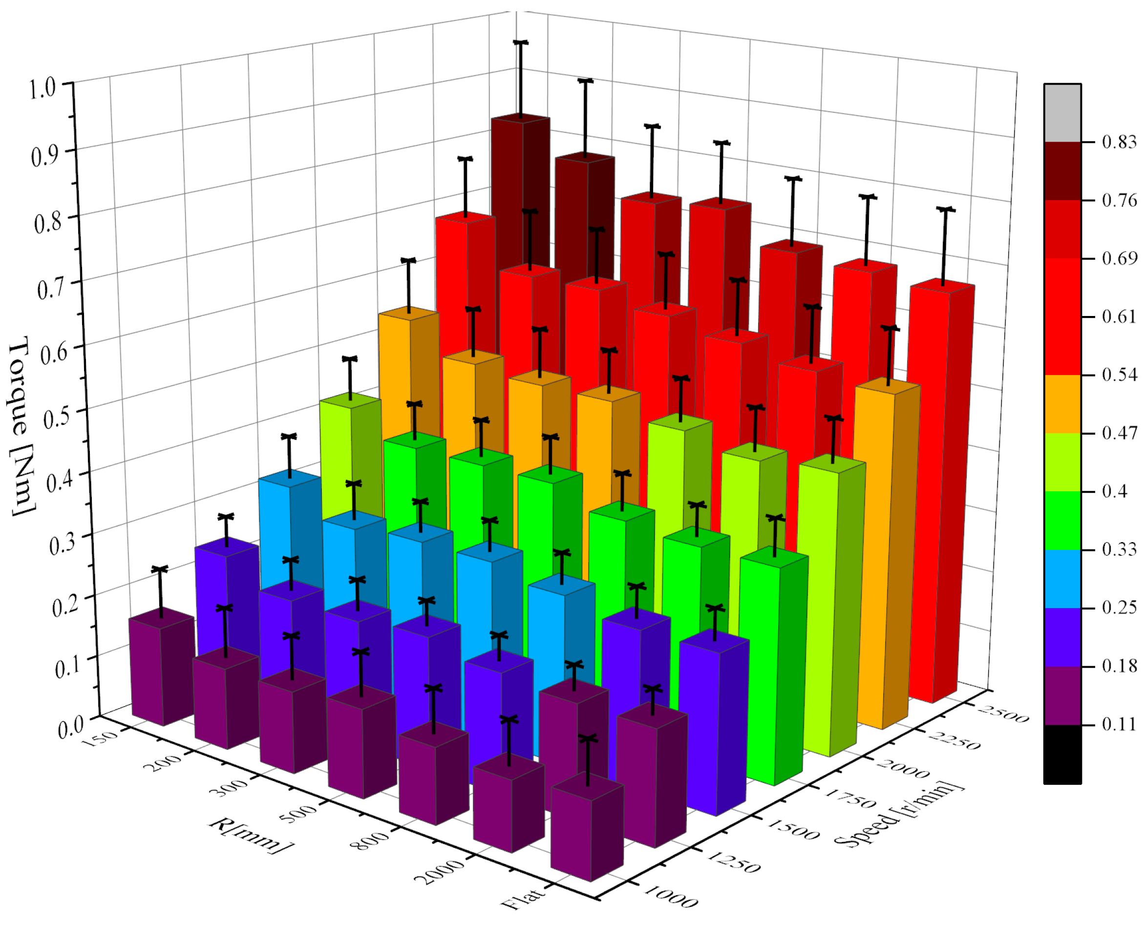
4.2.3. Required Torque

Figure 13 illustrates the experimental results of suction cup torque measured across various curved surfaces and rotational speeds. It is evident from Figure 11 that the torque exerted by the suction cup increases proportionally with the rotational speed. Additionally, diminishing the curvature of the adsorption surface leads to an elevation in the torque requirement for the suction cup. This phenomenon occurs due to the enlargement of the maximum adsorption gap as the curvature radius decreases. Consequently, this intensifies the leakage of high-speed fluid from the suction cup, thereby increasing the fluid speed and energy exchange both within and outside the suction cup. This heightened exchange exacerbates the torque demand of the suction cup.

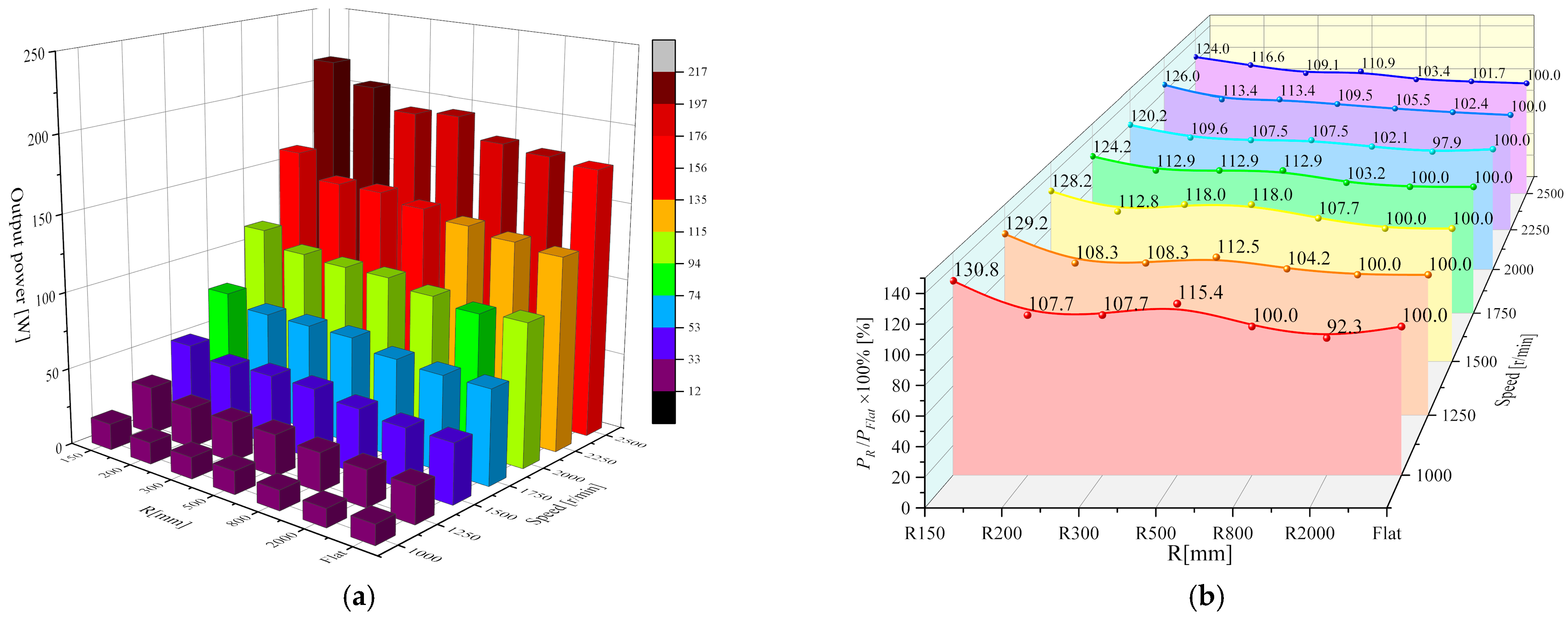
4.2.4. Power Consumption

In some power-sensitive underwater robots, especially those equipped with batteries, strict limitations are imposed on the overall power consumption in order to achieve longer operating times. Therefore, it is imperative to conduct a comprehensive analysis of the power consumption associated with the vortex suction cup subsequent to evaluating its adhesive force and requisite torque.
Different motors exhibit varying levels of efficiency, and the efficiency of a single motor can also fluctuate at different speeds and torques. Consequently, this study uses the motor’s output power as an indicator of the suction cup’s power to minimize the impact of motor efficiency. Based on the relationship between motor rotation and torque, its output power can be calculated as follows:
P = n 60 2 π T
In the equation, P represents the power in watts (W), n denotes the impeller speed measured in revolutions per minute (r/min), and T signifies the suction cup torque expressed in Newton meters (Nm).
The torque data obtained at different speeds were substituted into Equation (4), and the power consumption diagram of the suction cup under various curved surfaces was obtained, resulting in Figure 14. As indicated by Equation (4), the power’s variation trend at constant speed aligns with that of torque. Thus, Figure 14a illustrates a notable increase in suction cup power with rising speed. Simultaneously, as the curvature of the adsorption surface diminishes, the suction cup’s power gradually escalates. To precisely quantify the impact of curvature alteration on suction cup power, we utilized the power when the adsorption surface was flat as a reference point. Comparisons of the percentage increase in power at different curvature radii, while maintaining the same rotational speed, are illustrated in Figure 14b. Transitioning from a flat adsorption surface to a curvature radius of R = 150 mm results in a power surge of approximately 20% to 30%.

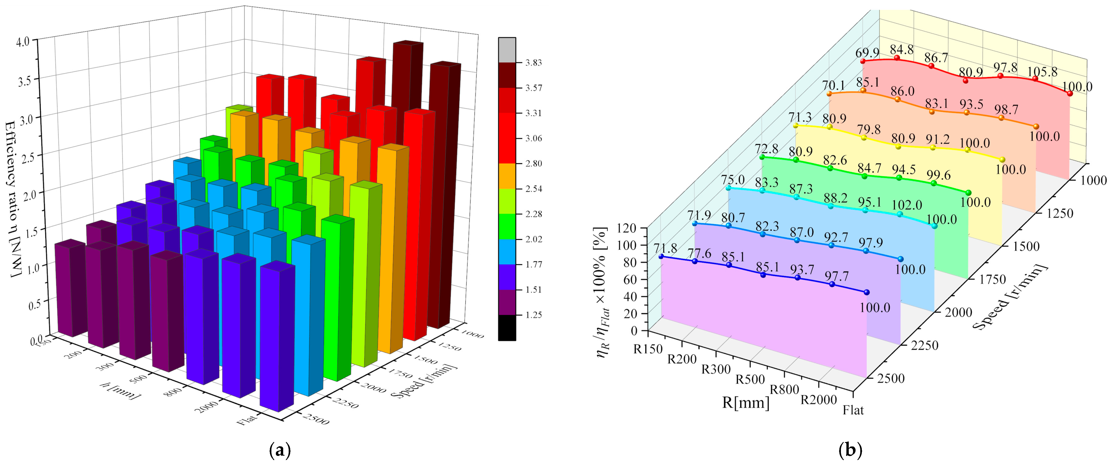
4.2.5. Adsorption Efficiency

In order to comprehensively evaluate the influence of adsorption surface curvature radii on the suction cup, we define the ratio of adhesive force F to power P as the adsorption efficiency η of the suction cup [28]:
η = F P
Equations (4) and (5) can be combined to obtain:
η = 30 F n π T
The physical significance of the adsorption efficiency η can be understood as the adhesive force obtained by the vortex suction cup for every watt of power consumed. The adsorption efficiency of the suction cup was determined by substituting the results of the adsorption force and torque into Equation (6), illustrated in Figure 15a. As depicted in the figure, the efficiency η of the suction cup decreases with increasing suction speed (note the altered direction of the speed axis for clarity). Simultaneously, a decrease in the curvature of the adsorption surface at constant speed also diminishes the suction cup’s adsorption efficiency. To precisely quantify the impact of changes in curvature on adsorption efficiency, we established the efficiency of the suction cup with a flat adsorption surface as the baseline. This allowed us to compare suction cup efficiency at various curvature radii under identical rotational speeds, as depicted in Figure 15b. Notably, the influence of curvature radius on suction cup efficiency remains consistent across speed segments. Transitioning from a flat to a curvature radius of R = 150 mm reduces adsorption efficiency by approximately 25% to 30%.

5. Conclusions

This paper presents the design of a vortex suction cup for use in underwater robots. By inducing high-speed rotating eddy currents within the chamber, negative pressure is generated, resulting in adsorption force. In practical applications, underwater detection robots encounter pipes of varying diameters, thus exposing the vortex suction cup to surfaces of different curvatures. To comprehensively understand the impact of surface curvature on adsorption performance, we conducted studies on the suction force and torque of the vortex suction cup under various curvature radii using CFD simulations and experimental tests. Both experiments and simulations indicate that decreasing the curvature radius of the adsorption surface results in reduced adsorption force and increased torque. As the surface transitions from flat to a curvature radius of R = 150 mm, the adsorption force of our proposed vortex suction cup decreases by approximately 10%, while the torque increases by 20% to 30%. To provide a comprehensive evaluation of curvature changes on suction cup performance, we developed an efficiency formula, unifying adsorption force and torque into a single parameter. Results show that decreasing the curvature radius leads to a decrease in suction efficiency, with a reduction of approximately 25% to 30% observed as the surface transitions to R = 150 mm curvature. These experimental findings offer insights for designing vortex suction cups for underwater vehicles and support their operational effectiveness. Future efforts will focus on optimizing the vortex suction cup’s structural design in order to enhance adsorption performance under small curvature radii. Given the integration of the vortex suction cup into underwater vehicles, particular attention will be given to the impact of robot motion on suction cup performance. Additionally, we will consider the influence of complex flow fields between multiple vortex suction cups on robot adsorption performance.

Supplementary Materials

The following supporting information can be downloaded at: https://www.mdpi.com/article/10.3390/jmse12040662/s1, Figure S1: Photos of simulated bodies with different adsorption surfaces.

Author Contributions

Conceptualization, Q.T., G.W., Y.D. and Z.L.; methodology, Q.T., Q.Z. and S.Z.; software, S.Z.; validation, Q.T. and Y.L.; formal analysis, Q.T.; investigation, Q.T., Y.D., Q.Z. and T.C.; resources, G.W.; data curation, Q.T.; writing—original draft preparation, Q.T.; writing—review and editing, L.W. and G.W.; visualization, Z.L.; supervision, Y.D., Q.Z. and G.W.; project administration, Y.D.; funding acquisition, L.W. and G.W. All authors have read and agreed to the published version of the manuscript.

Funding

This work was funded by The National Key Research and Development Program of China (Grant No. 2023YFB3407702), and the National Natural Science Foundation of Heilongjiang Province (Grant No. YQ2020E028).

Institutional Review Board Statement

Not applicable.

Informed Consent Statement

Not applicable.

Data Availability Statement

The data presented in this study are available on request from the corresponding author.

Conflicts of Interest

Authors Ying Du and Qiang Zhao were employed by Offshore Oil Engineering Co., Ltd. (Tianjin, China). The remaining authors declare that the research was conducted in the absence of any commercial or financial relationships that could be construed as a potential conflict of interest.

References

  1. Bhattacharyya, S.; Asada, H.H. Control of a Compact, Tetherless ROV for In-Contact Inspection of Complex Underwater Structures. In Proceedings of the IEEE/RSJ International Conference on Intelligent Robots and Systems (IROS), Chicago, IL, USA, 14–18 September 2014; pp. 2265–2272. [Google Scholar]
  2. Hirai, H.; Ishii, K. Development of Dam Inspection Underwater Robot. J. Robot. Netw. Artif. Life 2019, 6, 18–22. [Google Scholar] [CrossRef]
  3. Sakagami, N.; Yumoto, Y.; Takebayashi, T.; Kawamura, S. Development of dam inspection robot with negative pressure effect plate. J. Field Robot. 2019, 36, 1422–1435. [Google Scholar] [CrossRef]
  4. Qin, Y.; Dong, S.; Pang, R.; Xia, Z.; Yang, J. Design and Kinematic Analysis of a Wall-climbing Robot for Bridge appearance Inspection. IOP Conf. Ser. Earth Environ. Sci. 2021, 638, 012062. [Google Scholar] [CrossRef]
  5. Iwahori, T.; Takebayashi, T.; Saltagami, N.; Kawainura, S. Computational and Experimental Investigation of a Negative Pressure Effect Plate for Underwater Inspection Robots. In Proceedings of the IEEE/SICE International Symposium on System Integration (SII), Iwaki, Japan, 11–14 January 2021; pp. 239–243. [Google Scholar]
  6. Yamada, D.; Takebayashi, T.; Kato, H.; Sakagami, N.; Kawamura, S. Underwater Robot with Negative Pressure Effect Plates for Maintenance of Underwater Structures. In Proceedings of the IEEE/ASME International Conference on Advanced Intelligent Mechatronics (AIM), Hong Kong, China, 8–12 July 2019; pp. 1092–1097. [Google Scholar]
  7. Souto, D.; Faina, A.; Pea, F.L.; Duro, R.J. Morphologically intelligent underactuated robot for underwater hull cleaning. In Proceedings of the IEEE International Conference on Intelligent Data Acquisition & Advanced Computing Systems: Technology & Applications, Warsaw, Poland, 24–26 September 2015. [Google Scholar]
  8. Tavakoli, M.; Viegas, C.; Marques, L.; Norberto Pires, J.; de Almeida, A.T. OmniClimbers: Omni-directional magnetic wheeled climbing robots for inspection of ferromagnetic structures. Robot. Auton. Syst. 2013, 61, 997–1007. [Google Scholar] [CrossRef]
  9. Fan, J.; Yang, C.; Chen, Y.; Wang, H.; Huang, Z.; Shou, Z.; Jiang, P.; Wei, Q. An underwater robot with self-adaption mechanism for cleaning steel pipes with variable diameters. Ind. Robot-Int. J. Robot. Res. Appl. 2018, 45, 193–205. [Google Scholar] [CrossRef]
  10. Yang, P.; Zhang, M.; Sun, L.; Li, X. Design and Control of a Crawler-Type Wall-Climbing Robot System for Measuring Paint Film Thickness of Offshore Wind Turbine Tower. J. Intell. Robot. Syst. 2022, 106, 50. [Google Scholar] [CrossRef]
  11. Guan, Y.; Zhu, H.; Wu, W.; Zhou, X.; Jiang, L.; Cai, C.; Zhang, L.; Zhang, H. A Modular Biped Wall-Climbing Robot With High Mobility and Manipulating Function. IEEE-ASME Trans. Mechatron. 2013, 18, 1787–1798. [Google Scholar] [CrossRef]
  12. Wang, J.-R.; Xi, Y.-X.; Ji, C.; Zou, J. A biomimetic robot crawling bidirectionally with load inspired by rock-climbing fish. J. Zhejiang Univ. Sci. A 2022, 23, 14–26. [Google Scholar] [CrossRef]
  13. Nassiraei, A.A.F.; Sonoda, T.; Ishii, K. Development of Ship Hull Cleaning Underwater Robot. In Proceedings of the Fifth International Conference on Emerging Trends in Engineering & Technology, Himeji, Japan, 5–7 November 2012. [Google Scholar]
  14. Chen, Y.Z.; Hu, Y.H. Research and Application of Ship Hull Fouling Cleaning Technologies. Surf. Technol. 2017, 46, 60–71. [Google Scholar]
  15. Chen, L.; Cui, R.; Yan, W.; Xu, H.; Zhao, H.; Li, H. Design and climbing control of an underwater robot for ship hull cleaning. Ocean Eng. 2023, 274, 114024. [Google Scholar] [CrossRef]
  16. Brusell, A.; Andrikopoulos, G.; Nikolakopoulos, G. Novel Considerations on the Negative Pressure Adhesion of Electric Ducted Fans: An Experimental Study. In Proceedings of the 25th Mediterranean Conference on Control and Automation (MED), Valletta, Malta, 3–6 July 2017; pp. 1404–1409. [Google Scholar]
  17. Chen, Y.; Liu, S.; Zhang, L.; Zheng, P.; Yang, C. Study on the adsorption performance of underwater propeller-driven Bernoulli adsorption device. Ocean Eng. 2022, 266, 112724. [Google Scholar] [CrossRef]
  18. Li, X.; Li, N.; Tao, G.; Liu, H.; Kagawa, T. Experimental comparison of Bernoulli gripper and vortex gripper. Int. J. Precis. Eng. Manuf. 2015, 16, 2081–2090. [Google Scholar] [CrossRef]
  19. Li, X.; Kagawa, T. Development of a new noncontact gripper using swirl vanes. Robot. Comput. Integr. Manuf. 2013, 29, 63–70. [Google Scholar] [CrossRef]
  20. Zhou, Q.; Li, X. Design of wall-climbing robot using electrically activated rotational-flow adsorption unit. In Proceedings of the 2016 IEEE/RSJ International Conference on Intelligent Robots and Systems (IROS), Daejeon, Republic of Korea, 9–14 October 2016. [Google Scholar]
  21. Dong, L.J.; Li, X.; Liu, H.; Tao, G.L. Development and Analysis of an Electrically Activated Sucker for Handling Workpieces With Rough and Uneven Surfaces. In Proceedings of the IEEE International Conference on Advanced Intelligent Mechatronics, Busan, Republic of Korea, 7–11 July 2015. [Google Scholar]
  22. Zhu, Y.; Zhou, R.; Yang, G.; Zhu, Y.; Hu, D. Experimental and numerical study of the adsorption performance of a vortex suction device using water-swirling flow. Sci. China-Technol. Sci. 2020, 63, 931–942. [Google Scholar] [CrossRef]
  23. Zhao, Y.B.; Yang, C.J.; Chen, Y.H.; Li, J.; Liu, S.Y.; Ye, G.Y. Study on the Optimal Design for Cavitation Reduction in the Vortex Suction Cup for Underwater Climbing Robot. J. Mar. Sci. Eng. 2022, 10, 70. [Google Scholar] [CrossRef]
  24. Fan, S.; Cheng, X.; Qiao, K.; Liu, S.; Xu, W. Optimization design and experimental validation of a vortex-based suction cup for a climbing AUV. Ocean Eng. 2022, 257, 111602. [Google Scholar] [CrossRef]
  25. Guo, T.; Liu, X.; Song, D. Innovative sliding negative pressure adsorptive approach applied to an underwater climbing adsorption robot. Phys. Fluids 2021, 33, 117107. [Google Scholar] [CrossRef]
  26. Darmawan, S.; Tanujaya, H. CFD Investigation of Flow Over a Backward-Facing Step Using AN RNG k-ε Turbulence Model. Int. J. Technol. 2019, 10, 280–289. [Google Scholar] [CrossRef]
  27. Almohammadi, K.M.; Ingham, D.B.; Ma, L.; Pourkashan, M. Computational fluid dynamics (CFD) mesh independency techniques for a straight blade vertical axis wind turbine. Energy 2013, 58, 483–493. [Google Scholar] [CrossRef]
  28. Tang, Q.; Du, Y.; Ding, M.; Zhang, S.; Zhao, Q.; Hu, S.; Tian, C.; Wang, L.; Li, Y.; Wang, G. Study on the performance of vortex suction cup for an underwater inspection robot. Ocean Eng. 2024, 300, 117462. [Google Scholar] [CrossRef]
Figure 1. Schematic diagram of the vortex suction cup.
Jmse 12 00662 g001
Figure 2. Vortex suction cup structure dimension definition diagram.
Jmse 12 00662 g002
Figure 3. Schematic diagram of vortex suction cup adsorbing gaps.
Jmse 12 00662 g003
Figure 4. Adsorption gap variation chart.
Jmse 12 00662 g004
Figure 5. Models for CFD simulations.
Jmse 12 00662 g005
Figure 6. The computational domain of the simulation.
Jmse 12 00662 g006
Figure 7. Schematic diagram of CFD meshing.
Jmse 12 00662 g007
Figure 8. Velocity distribution under different curvature radii.
Jmse 12 00662 g008
Figure 9. Pressure distribution under different curvature radii.
Jmse 12 00662 g009
Figure 10. Testing platform for vortex suction cup.
Jmse 12 00662 g010
Figure 11. Relative error between simulations and experimental.
Jmse 12 00662 g011
Figure 12. Adsorption force of suction cups under different curvature radii. (a) Experimental results of adhesion force of vortex suction cups under different curvatures. (b) Adhesion force percentage curve of vortex suction cups under different curvatures.
Jmse 12 00662 g012
Figure 13. Required torque of suction cups under different curvature radii.
Jmse 12 00662 g013
Figure 14. Power consumption of suction cups under different curvature radii. (a) A calculation of the power consumption of vortex suction cups under different curvatures. (b) Power consumption percentage curve of vortex suction cups under different curvatures.
Jmse 12 00662 g014
Figure 15. Adhesion efficiency of suction cups under different curvature radii. (a) A calculation of the adhesion efficiency of vortex suction cups under different curvatures. (b) Adhesion efficiency percentage curve of vortex suction cups under different curvatures.
Jmse 12 00662 g015
Table 1. Dimensions of vortex suction cup.
HH1H2rr1r2r3r4φ
10 mm1.3 mm0.7 mm10 mm42.3 mm58.5 mm60 mm70 mm150°
Table 2. Grid independence verification results.
CoarseMediumFine
Basic size 0.12 (mm)0.1 (mm)0.08 (mm)
Mesh quantity764,0241,142,6221,989,966
Simulation force270 (N)270 (N)269 (N)
Simulation torque0.88 (Nm)0.91 (Nm)0.91 (Nm)
Table 3. Data for simulation and experimental comparison.
Adsorption Surface
Curvature Radius (mm)
Experimental Force (N)Simulated Force (N)Experimental Torque (Nm)Simulation Torque (Nm)
1501731730.560.54
2001791750.490.49
3001811800.450.48
5001851820.480.48
8001861860.470.46
20001871910.460.44
Flat1911920.460.45
Disclaimer/Publisher’s Note: The statements, opinions and data contained in all publications are solely those of the individual author(s) and contributor(s) and not of MDPI and/or the editor(s). MDPI and/or the editor(s) disclaim responsibility for any injury to people or property resulting from any ideas, methods, instructions or products referred to in the content.

