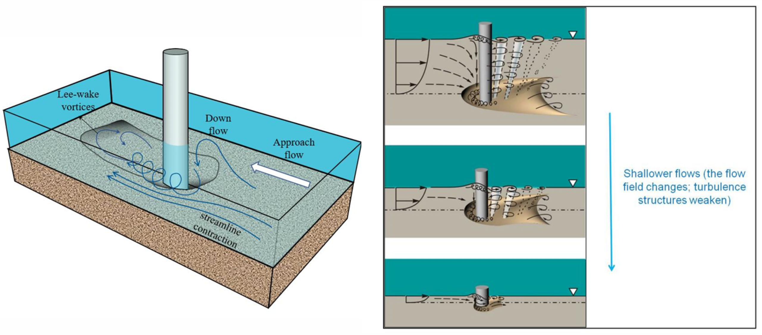
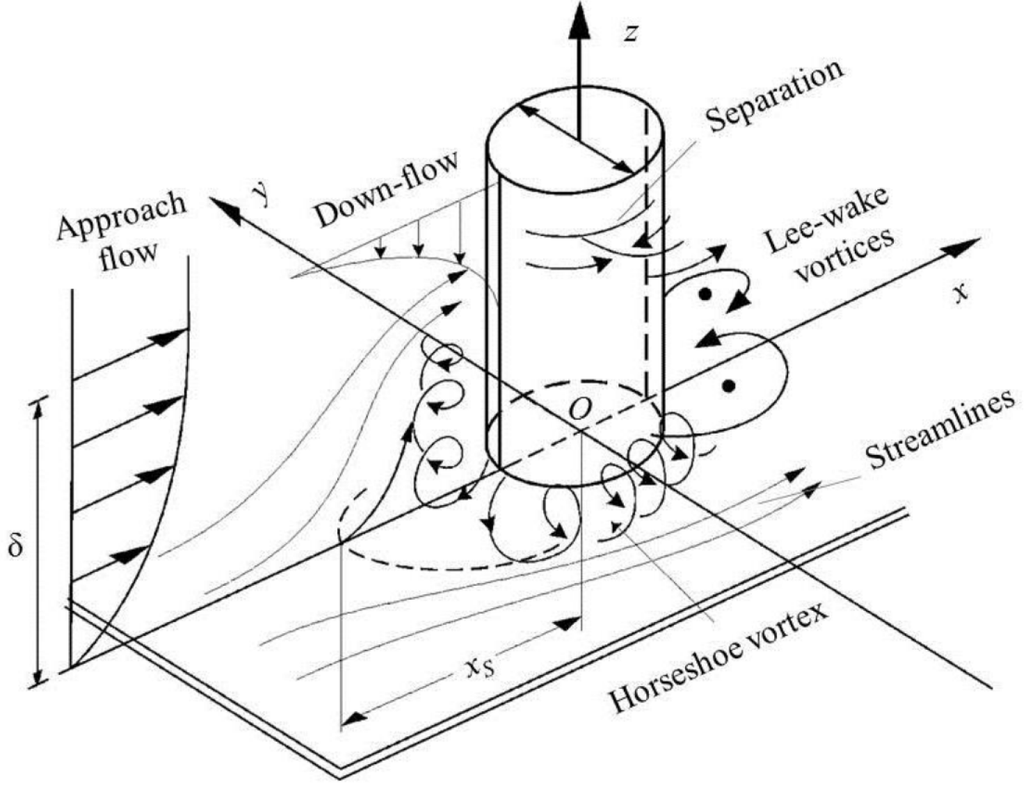
The formation of a horseshoe vortex in front of the pile requires two necessary conditions [
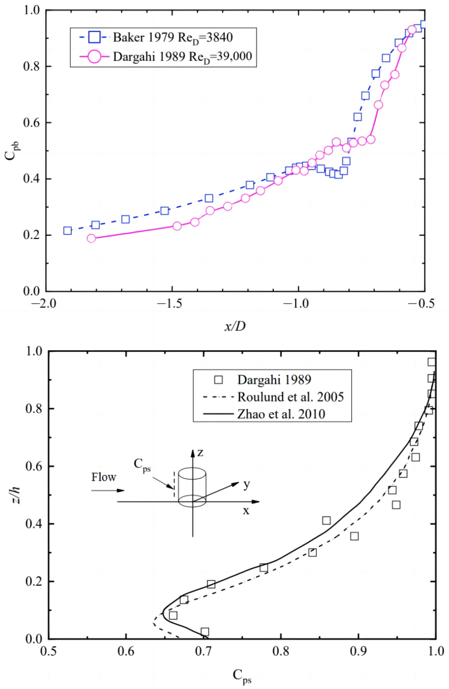
32]: the existence of a boundary layer for the traveling water in front of the pile, and a sufficiently large reverse pressure gradient in front of the pile. On this basis, Du et al. [
34,
35] summarized Baker [
36], Dargahi [
37], Roulund [
33], Zhao [
38], etc., for the study of the pressure in front of the pile, and concluded that the pressure is not uniformly distributed along the water depth near the pile surface. The pressure distribution is shown in
Figure 14, along the height direction of the pile [
34]. This uneven pressure distribution in front of the pile causes the boundary layer separation between the flow and the pile surface, thus creating an initial horseshoe vortex that, once formed, in turn increases the pressure at the bed surface. This is the main hydrodynamic factor for local scour generation. The main function of the flow-altering protection scheme is to reduce the scouring effect by reducing the pressure difference in front of the pile.
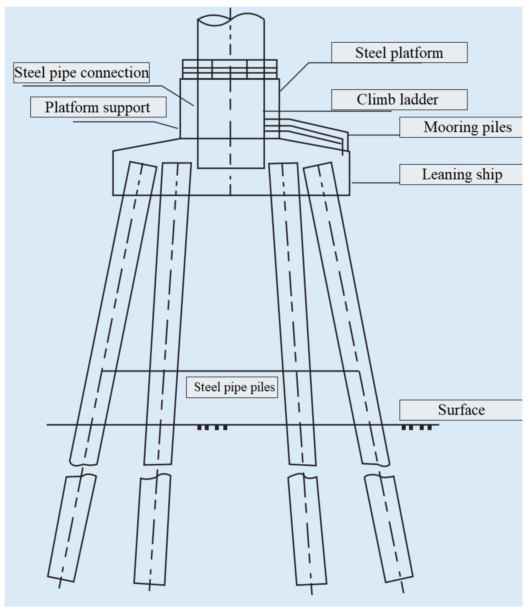
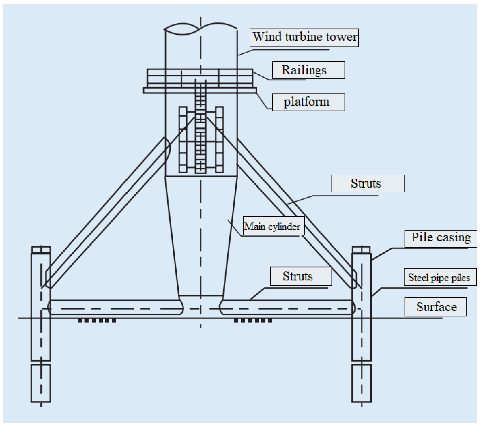
Figure 13.
Monopile foundation pile circumferential field structure (with permission from
Journal of Marine Science and Engineering, 2020, open access) [
33,
35].
4.1. Openings through Piers Scheme
There are three main forms of the openings through a piers scheme: internal flow-guiding tube, pile slots, and equivalent piles (group pile replacement) [
21].
Table 4 shows the maximum and minimum scour reduction rate for openings through a piers scheme.
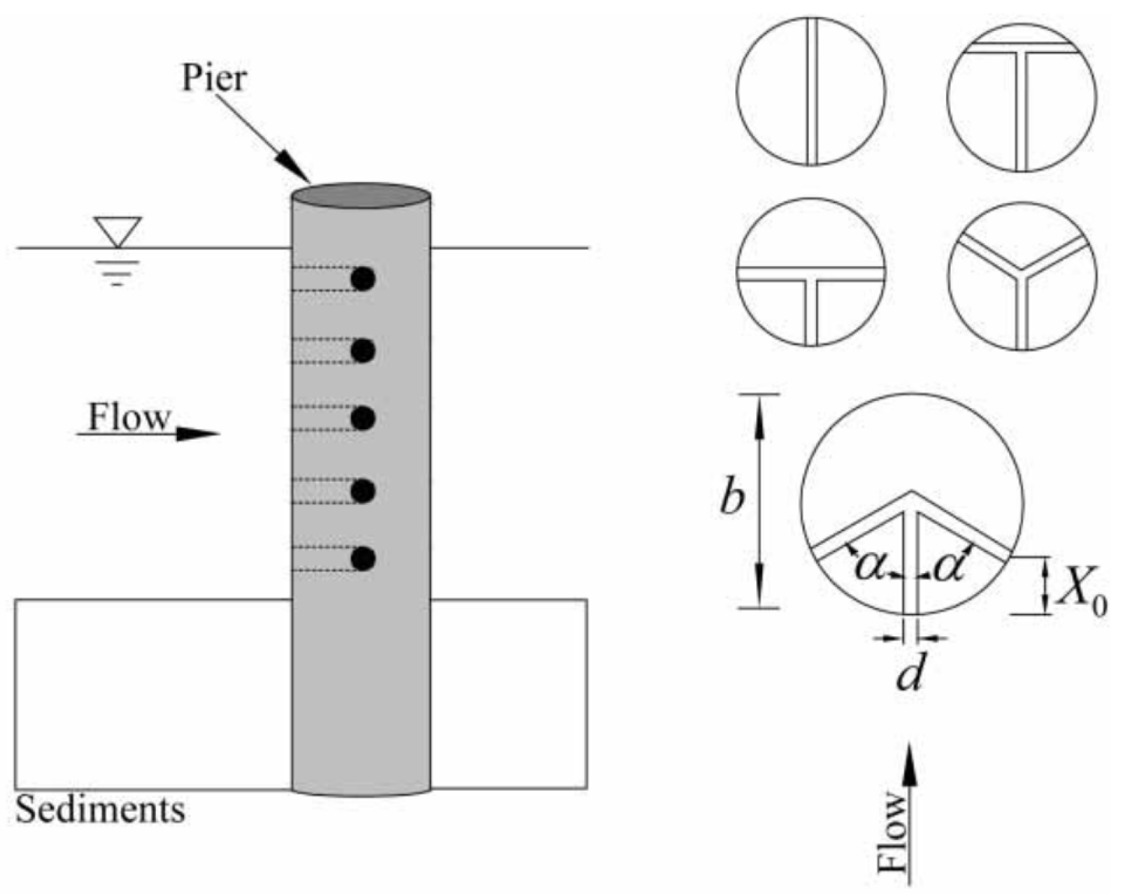
Internal flow-guiding tube scheme reduces the pressure difference generated by the current in front of the pile by cutting several holes in the pile body and guiding the current through the holes to pass through the structure, thus achieving the effect of scour resistance.
Figure 15 shows a deflector structure, for which
and
d represents the angle and diameter of the inner flow-guiding tube. The scour protection ability of this scheme was found to be related to the hole diameter
d and the Froude number
[
21]. El-Razek et al. [
39] found that this protection scheme can reduce the scour depth by a maximum of 39%. Somaye et al. [
40] reduced the maximum scour depth of 37.5% by a similar arrangement. Entesar [
41] found that the maximum scour depth was reduced by 45% and the scour volume was reduced by 68% by arranging the deflector tube in the pile body.
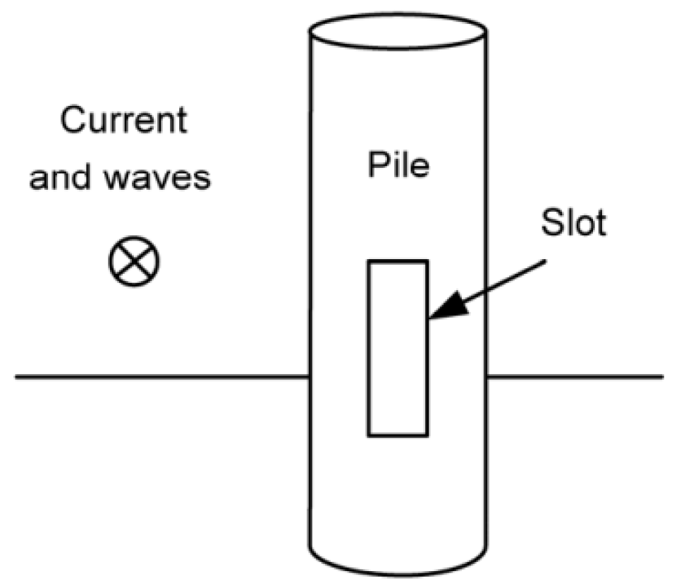
Pile slots are used to reduce the effect of scouring by opening inflow slots on the structure to guide the flow diversion through the structure and reduce the pressure in front of the structure pile, as shown in
Figure 16. It is generally believed that the larger the diameter of the hole, the stronger its scouring protection [
15,
21,
41,
42,
43]. Liang et al. [
44] adjusted the hole size and arrangement position in the experiment, the scour depth reduction rate was always below 26.1% under the unidirectional flow and wave-current coupling conditions, thus the scour protection effect was considered less than ideal. In other experiments, the single slotting scheme only has a scour depth reduction rate less than 35%, such as the experiments of Tafarojnoruz et al. [
45]. It can achieve a scour depth reduction of 35% scour protection effect in the most ideal condition when its opening diameter is maximum. The combination of pile grooving and other protection methods to form a combined protection scheme can achieve a better scour protection effect in some experiments, such as Grimaldi et al. [
46], who combined the grooving method with a sand barrier to have a maximum scour depth reduction of 45%. Gaudio et al. [
47] combined the grooving scheme with a horizontal plate, which could have a maximum scour depth reduction of 81.8%.
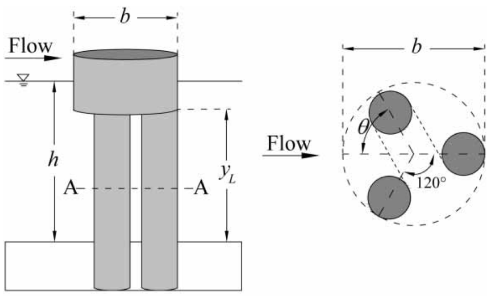
Equivalent piles are used for local scour reduction by replacing a monopile with a group pile structure of equal support capacity, as shown in
Figure 17. The parameter
represents the length of equivalent piles. Vittal et al. [
48] arranged three structures at 120
° instead of a monopile structure and has a scour protection capability of 39% reduction in maximum scour depth.
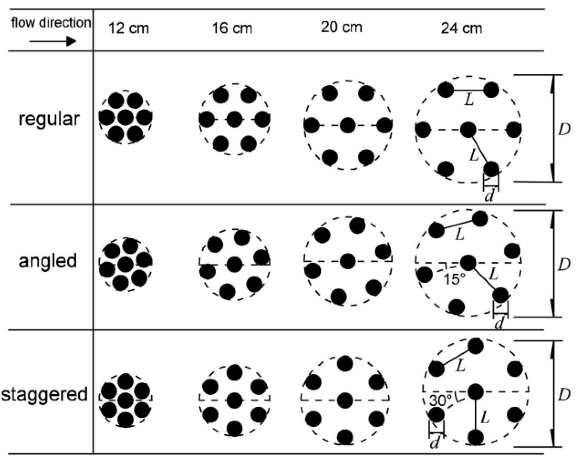
Oral et al. [
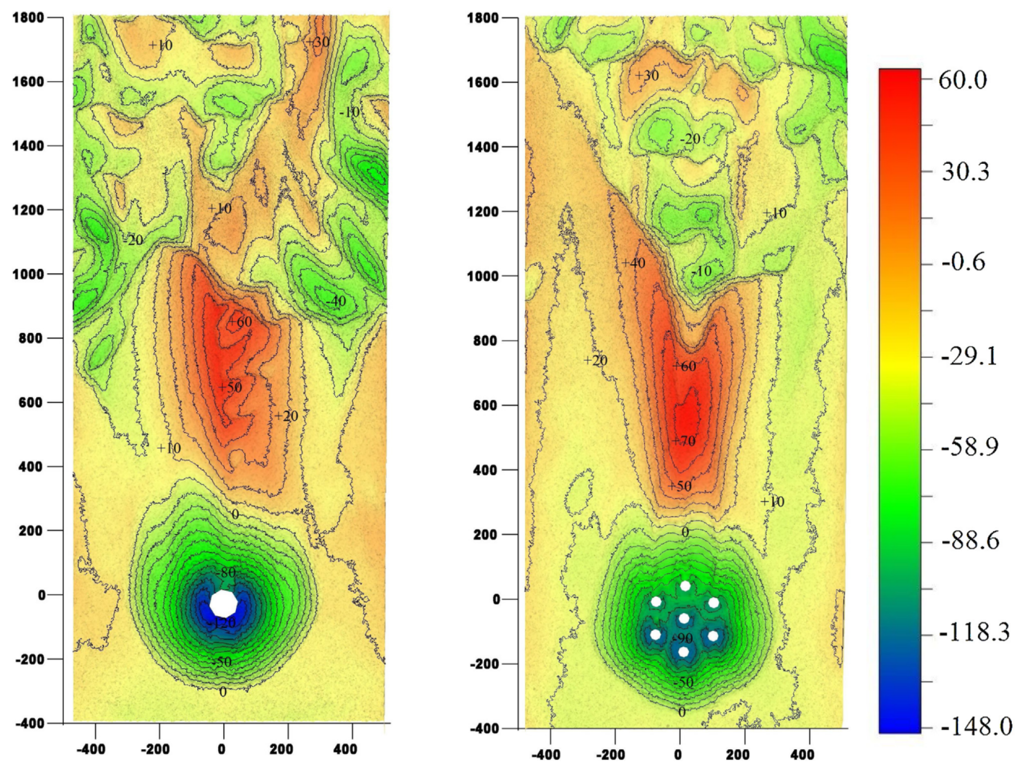
49] investigated the use of cylindrical hexagonal arrays as equivalent pile structures, set four array densities of 0.14, 0.2, 0.32, and 0.56, and compared them with a single circular pile having the same area, as shown in
Figure 18. The experimental results found that for the combination of equivalent piles with higher array densities, the scour characteristics are similar to those of individual solid cylinders, showing more of their overall scour characteristics. When the array density of the equivalent pile combination is smaller, the local scour characteristics of individual cylinders start to become obvious. In addition, the equivalent piles can reduce the maximum scour depth and scour volume compared with the same square of single cylinder. The whole column arrangement with lower density has better scour protection effect, when the array density is 0.14, as shown in
Figure 19. The maximum scour depth can be reduced by 22% and the scour volume can be reduced by 27% [
49]. It can be concluded that the load-bearing capacity of the support structure depends largely on its cross-sectional area, and the experimental results show that the equivalent pile structure of hexagonal array can be used as an alternative to monopile support, −1.0.
4.2. Structure Attachment
The structural attachment method achieves the effect of changing the flow field and thus reducing scour by installing accessory structures around the pile foundation and the pile body. Such protection schemes usually have specific options such as horizontal plates (also known as collars), vertical plates, vanes, pile threads, rough pile bodies, and extended foundations.
Table 5 shows the maximum and minimum scour reduction rate for structural attachments scheme.
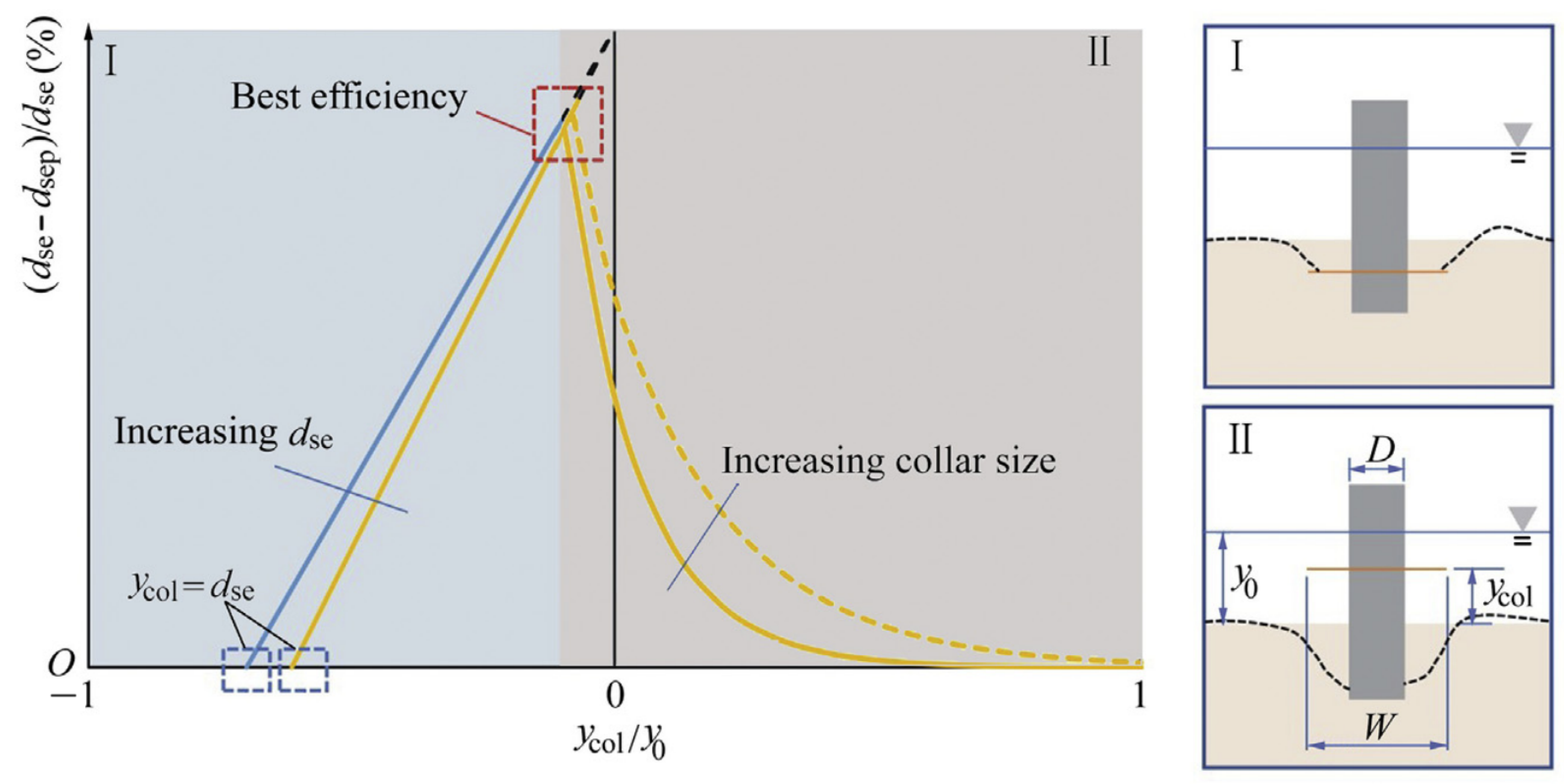
The collar schemes are divided into two main categories. One is placed above the bed surface to reduce the scour by preventing the water from diving in front of the pile. Another type is usually arranged at the bed surface or at the position where the top plate is flush with the bed surface, which generally acts directly on the bed surface to protect it from scour.
The placement height of the horizontal plate is a major factor affecting its scour protection effect. Moncada-M et al. [
50] found that when the horizontal plate was arranged on the bed surface or under the bed surface, its position could effectively reduce scouring, mainly playing the effect of the horizontal plate directly protecting the bed surface. Tafarojnoruz et al. [
45] found through experiments that under certain hydrodynamic environmental conditions the protection effectiveness of horizontal plates arranged above the bed surface is weaker than that of protection schemes such as sacrificial piles and pile trenching; however, horizontal plates can be easily combined with other protection schemes and applied as a supplementary scheme. Pandey et al. [
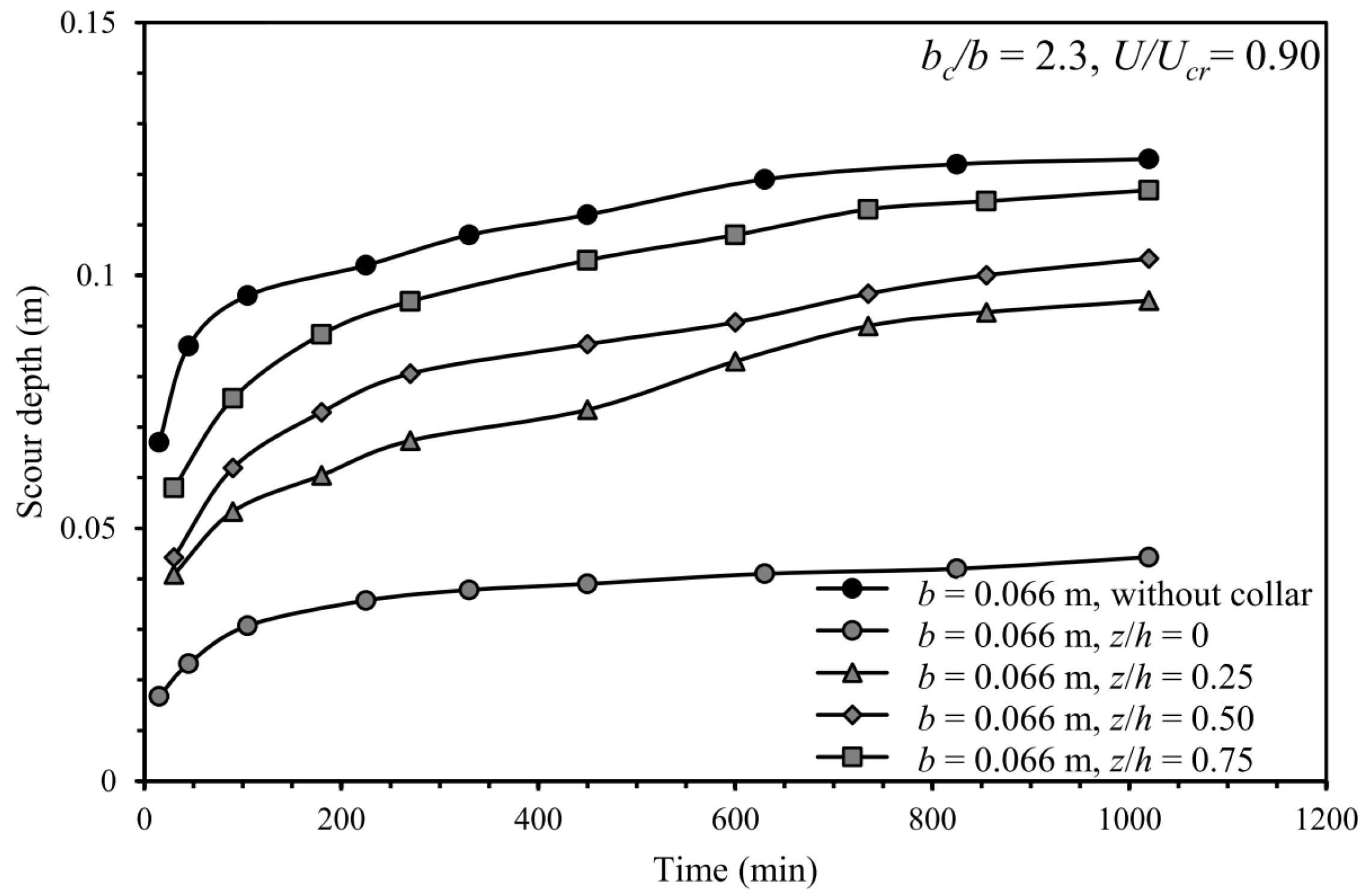
86] found that the horizontal plate scheme can effectively reduce the maximum depth compared with the control group without protection scheme, and the development pattern of maximum scour depth over scouring time is consistent with the unprotected group, as shown in
Figure 20. Mashahir et al. [
87] concluded that, compared with the unprotected control group, the maximum depth of scour under horizontal plate protection is inconsistent with the unprotected group.
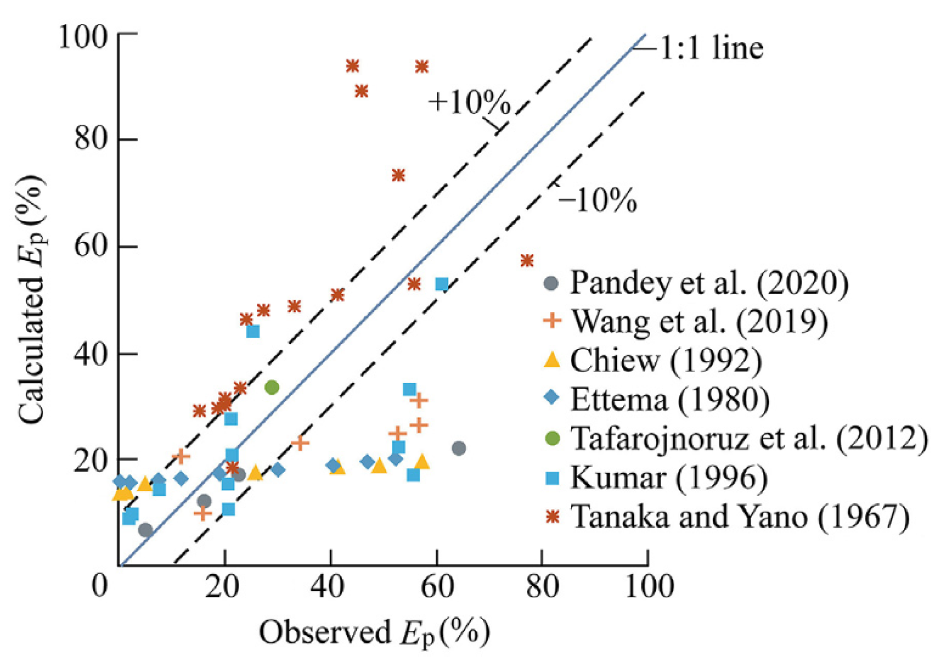
Kumar et al. [
43] gave the following predictive equation for the scour protection capacity of horizontal plates:
where
W is the diameter of the horizontal plate;
D is the diameter of the structure;
is the water depth; and
is the position of the plate from the bed. Tang et al. [
15] compared the experiment results of the physical model with the predicted values of the above equation, and found that the protection effect predicted by the equation had a large deviation from the actual measured values, as shown in
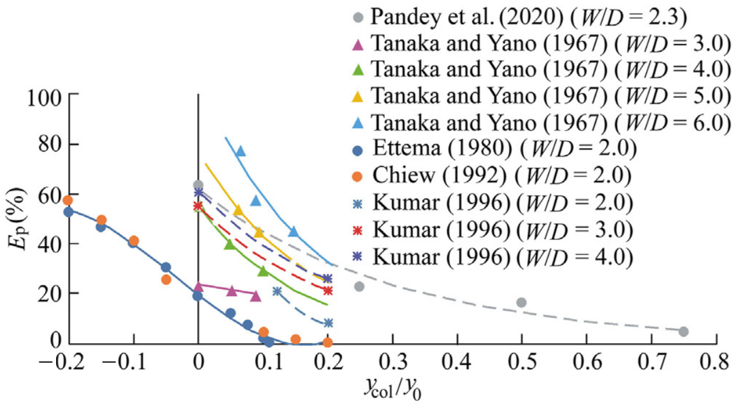
Figure 21. The protection ability of the horizontal plate under different hydrodynamic environments is not consistent, as shown in
Figure 22. This phenomenon may be related to factors such as flow velocity and sediment particle size.
When the horizontal plate is placed below a certain position on the bed, the volume of scour below the horizontal plate is very small [
15,
51]. When it is higher than this position, more scour will be generated below the horizontal plate. The scouring protection ability is weakened with the increase in the height of the placement position, as shown in
Figure 23. Therefore, when considering the horizontal plate protection scheme, we should first consider the layout position in the horizontal plane or the area below it. For the effect of horizontal plate diameter on scour protection ability, Liang et al. [
44] experimentally concluded that diameters of three times the pile diameter have better scour protection ability than those that are two times the pile diameter.
Vertical plates and vanes are another major category of structural attachments. In 1960s, researchers began to conduct research on such scour protection schemes, using flat plates and vanes to reduce the scour depth [
21]. It has been suggested that such protection schemes can separate the flow around the pile structure and thus reduce the strength of the horseshoe vortex [
53]. The vane scheme shown in
Figure 24 can reduce the scour depth by 90% [
21].
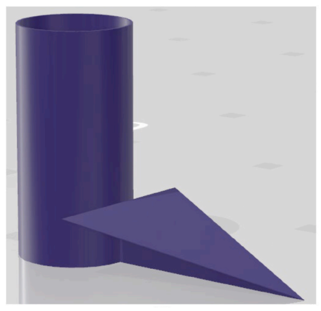
Gupta proposed a triangular vane, which placed at the bottom of the structure as shown in
Figure 25. It can destroy the flow characteristics at the bottom of the structure and reduce the strength of the horseshoe vortex [
54]. The experimental results of this scheme showed that the scour depth was reduced by 32% in unsteady flow and 67% in the experimental clear water velocity condition.
Aly-Mousaad et al. [
11] demonstrated by the computational fluid dynamics (CFD) method that the triangular vane protection scheme can reduce the bed shear stress by about 30% under certain water flow conditions, which in turn reduces the scour volume and scour depth. The vertical plate scheme can be reduced 10–15%. The paper reveals the mechanism of the triangular vane scheme and theoretically demonstrates the feasibility of the scheme.
The structure of the vertical plate scheme is shown in
Figure 26. Dey et al. [
60] found that the vertical plate scheme can reduce the maximum scour depth by 61.6% on average. Khaple et al. [
55] concluded that the ability of scour protection increases with the increase in vertical plate length, and this ability is independent of the sediment particle size. Khaple et al. [
56] found experimentally that the vertical plate length has the best scour protection ability when it is twice the pile diameter, and the maximum scour depth is reduced by 42.4%, and the authors proved that this scheme significantly weakens the pile front vortex structure by observing the flow field. In the experiments of Gaudio et al. [
47], the maximum scour depth was reduced by 25.3% when two symmetrical submerged vertical plates were placed on both sides of the pile front and combined with the sand barrier scheme. Ghorbani et al. [
57] investigated the effect of the placement angle and position of the submerged vertical plate on scouring, and concluded that the best scouring protection effect was achieved when the vertical plate was set directly in front and the opening angle was 18.5
°.
Increasing the pile roughness and threaded piles can be seen as one class of scour protection schemes. Ghodsian et al. [
58] argued that introducing rough structures or attaching rough elements to the surface of existing structures generates minute turbulence on the surface and generates kinetic energy upstream of the jetty, thus delaying the water separation and moving the delay point downstream of the pile. As a result, the intensity of the horseshoe vortex is weakened and moved away from the riverbed. Ghodsian et al. therefore concluded that the method of roughing the surface of structures is effective in reducing the maximum depth of scour and the volume of scour. Fahmy Salah [
59] experimentally evaluated the efficiency of different roughness on the surface of circular piers. The effectiveness of increasing the surface roughness of the structure in reducing the maximum scour depth and influencing the upstream slope angle of the regional scour pit was demonstrated. It was observed experimentally that roughed piers could reduce the maximum scour depth, the impact area and the scour volume reduced by 29.6%, 13.7%, and 42.52%, respectively.
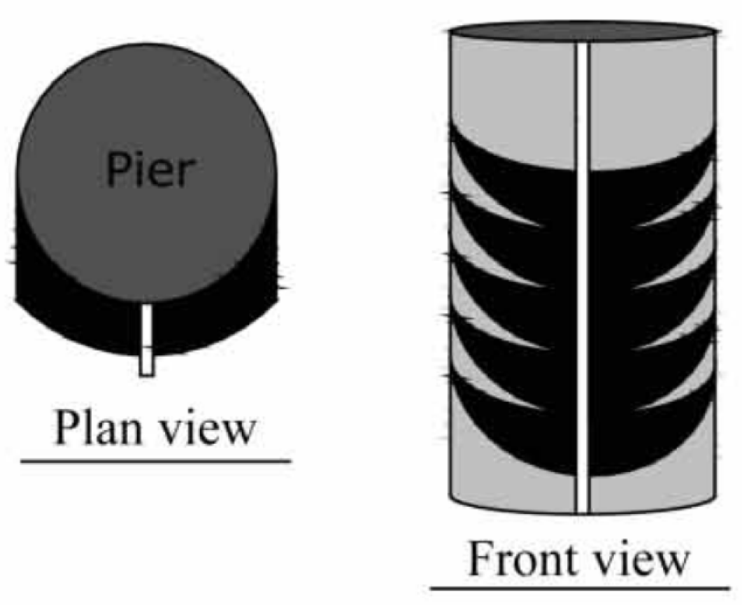
Threaded piles are designed to change the flow field and reduce scour by wrapping cables around the perimeter of the pile. Dey et al. [
60] first proposed this scheme, which controls the flow field around the pile and the scour around structure by using one, two, or three cables wrapped around the body of the structure. The maximum scour depth reduction under wave conditions was 46.3% when the thread diameter to pile diameter ratio was 0.1 and the thread winding angle was 15
°. Izadinia et al. [
61] investigated the effect of the scheme of threaded piles and the combination of threaded piles and horizontal plates on the scour depth reduction. The best protection effect was achieved when the ratio of thread diameter to pile diameter was 0.15 and the thread winding angle was 15
°. The scour reduction was 12.85%. The maximum scour depth reduction was 52.85% when the combination of threaded pile and horizontal plate scheme was used for protection. In the experiment of Valentin et al. [
62], the reduction in scour depth of threaded piles was 32% and 52% for coarse and fine sediments, respectively, and it was found that the scour protection was more effective for the bed of fine sediments as the thread diameter increased. Vahdati et al. [
63] investigated the effect of threaded piles on scouring of group piles and found that the maximum scour depths of the front and rear piles were reduced by 46% and 12%, respectively. Threaded piles scheme had no scouring protection effect in the experiments with three downstream side-by-side piles.
Extended foundations usually extend the diameter range of the foundation. In offshore wind power and other marine projects, the foundations of structures in offshore are vulnerable to scouring. Usually gravity foundations can reduce the impact of scouring [
5,
92]. Chiew [
42] and Coleman [
93] argue that extended foundations not only increase the load-bearing capacity of structures, but also have the effect of reducing scour. Wu et al. [
5] argue that the application of gravity-based foundations is usually in sea area less than 10 m water depth.
Melville et al. [
64] demonstrated the effectiveness of the extended foundation scheme for scour protection by experiments and proposed that the foundation installation location
Y should be below the bed surface and
,
D is the pile diameter of the structure. The maximum scour depth reduction rate of the group with the best effect in their experiments was 50%. Liang et al. [
44] found that the extended foundation with three times the pile diameter has better scour protection effect compared with the extended foundation with two times the pile diameter, and the maximum scour depth is reduced by 89.4% and 61%, respectively. Yao et al. [
65] found that, unlike the scour development pattern under an unprotected foundation, scour development under an extended foundation starts from behind the pile and extends to the front of the pile. The extended foundation can delay the local scour development process, and no significant scour is generated at the beginning of scour initiation compared to the control group without the scour protection scheme.
4.3. Bed Attachment Scheme
The bed attachment scheme refers to the effect of changing the characteristics of the flow field around the structure and thus reducing the scouring volume by influencing the wave and current through the structures placed on the sea bed, and there are mainly the following types: sacrificial piles, deflectors, sand barriers, etc.
Table 6 shows the maximum and minimum scour reduction rate for the bed attachment scheme.
Sacrificial piles are the most common scour protection scheme installed in the sea bed. See
Figure 27. The effect of altering the flow field around the protected structure is achieved by installing one or more flow disturbance piles in front of or around the pile. These sacrificial piles are subject to scour erosion, creating a highly deflected flow around the structure and thus creating a low scour capacity wake behind the sacrificial piles to protect the structure behind from erosion [
66,
67]. Melville et al. [
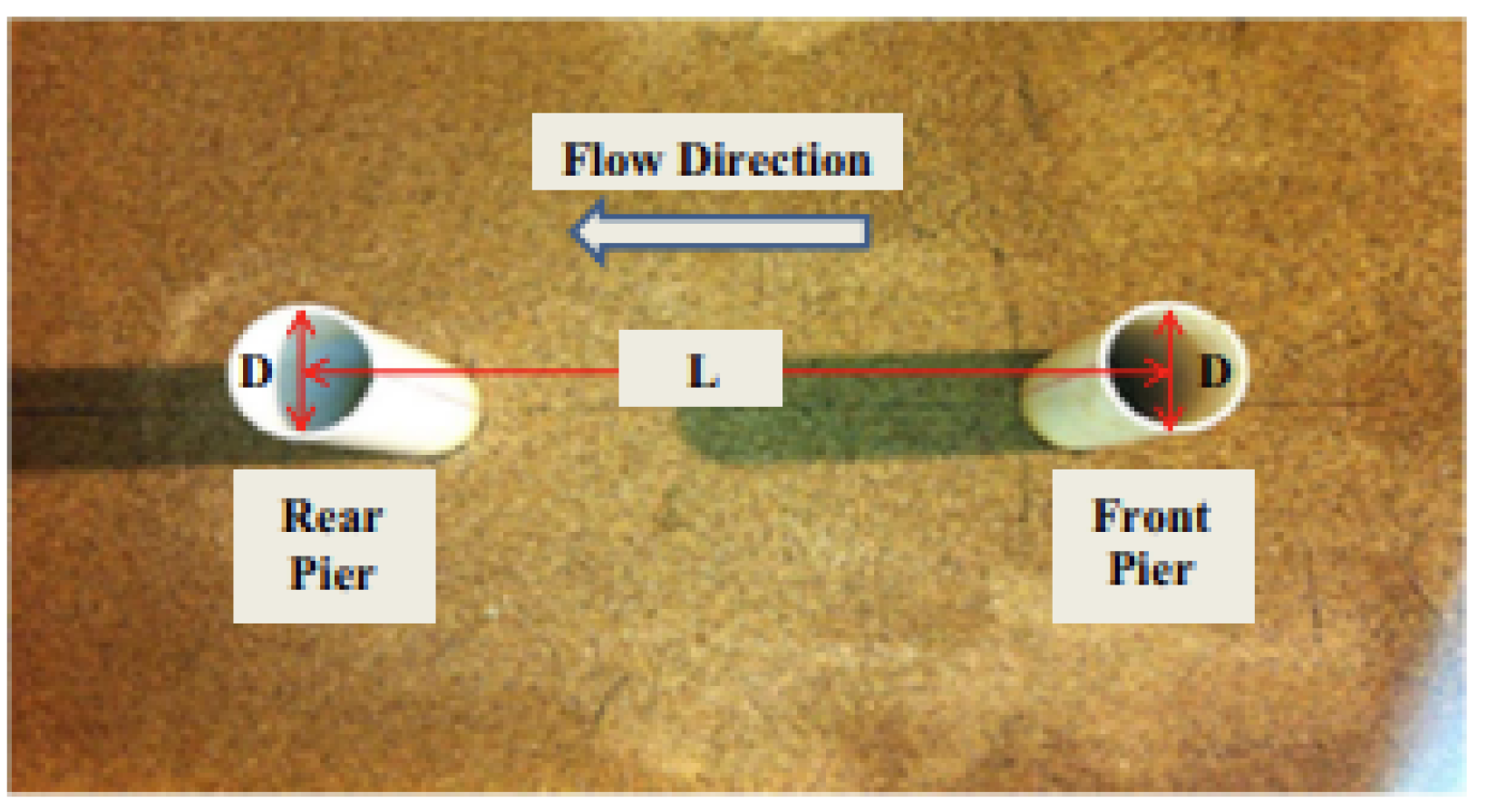
64] argue that the effectiveness of the sacrificial pile scheme depends on factors such as its number, size relative to the protected piles, geometric arrangement order, and characteristics of the flow field. Keshavarzi et al. [
68] experimentally explored the effect of the distance between the front and rear piles on the scour of the pile foundation and found that the scour of the sacrificial piles increased with the spacing when the spacing between the two piles was
, and the maximum scour depth of the front pile was 22% greater than that of the rear pile when
. When
, Garg et al. [
69] found that the protection scheme of placing a sacrificial pile in the headwater direction could reduce the maximum scour depth by 39%. The same phenomenon observed by Keshavarzi et al. [
68], where violent scouring occurs near the front pile and the upstream sacrificial pile protects the downstream main pile from the direct impact of the impinging water flow. Garg et al. [
69] also found in their experiments that the maximum 100% scour protection could be achieved when a horizontal plate of 3 times the pile diameter was combined with the sacrificial pile for protection. Ranjbar-Zahedani et al. [
70] designed a triangular block placed in front of the pile, as shown in
Figure 28, which can reduce the maximum scour depth of the post-pile by 40–60%. Tafarojnoruz et al. [
45] designed a pile-rowing scheme that can reduce the maximum scour depth by 32.2%.
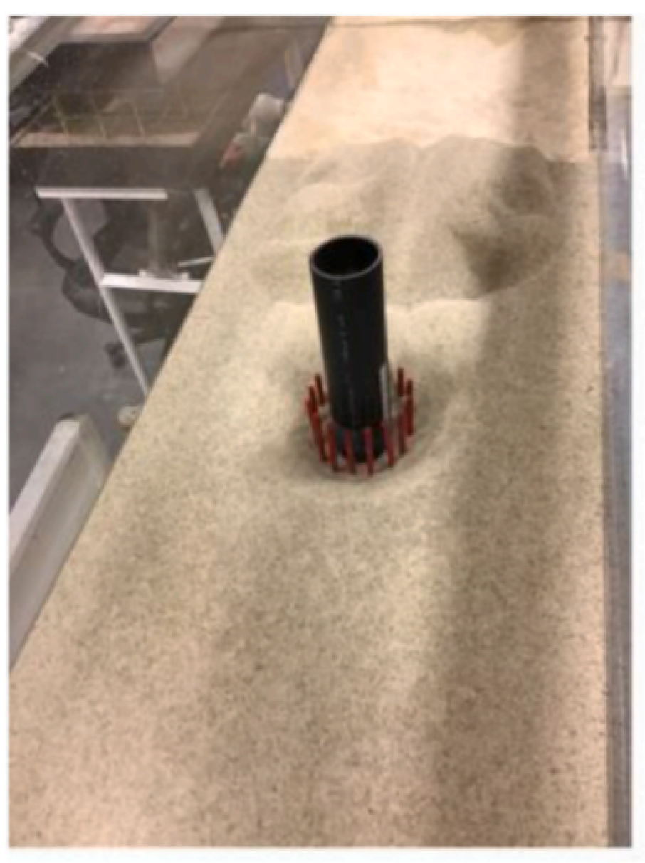
In addition, Li et al. [
72], inspired by mangrove protection of shoreline, proposed a wrap-around skirt pile as a protection measure for monopile scour protection scheme, as shown in
Figure 29. The maximum scour depth reduction rate of this method is 65%, which can reduce the sediment scour volume by 90%.
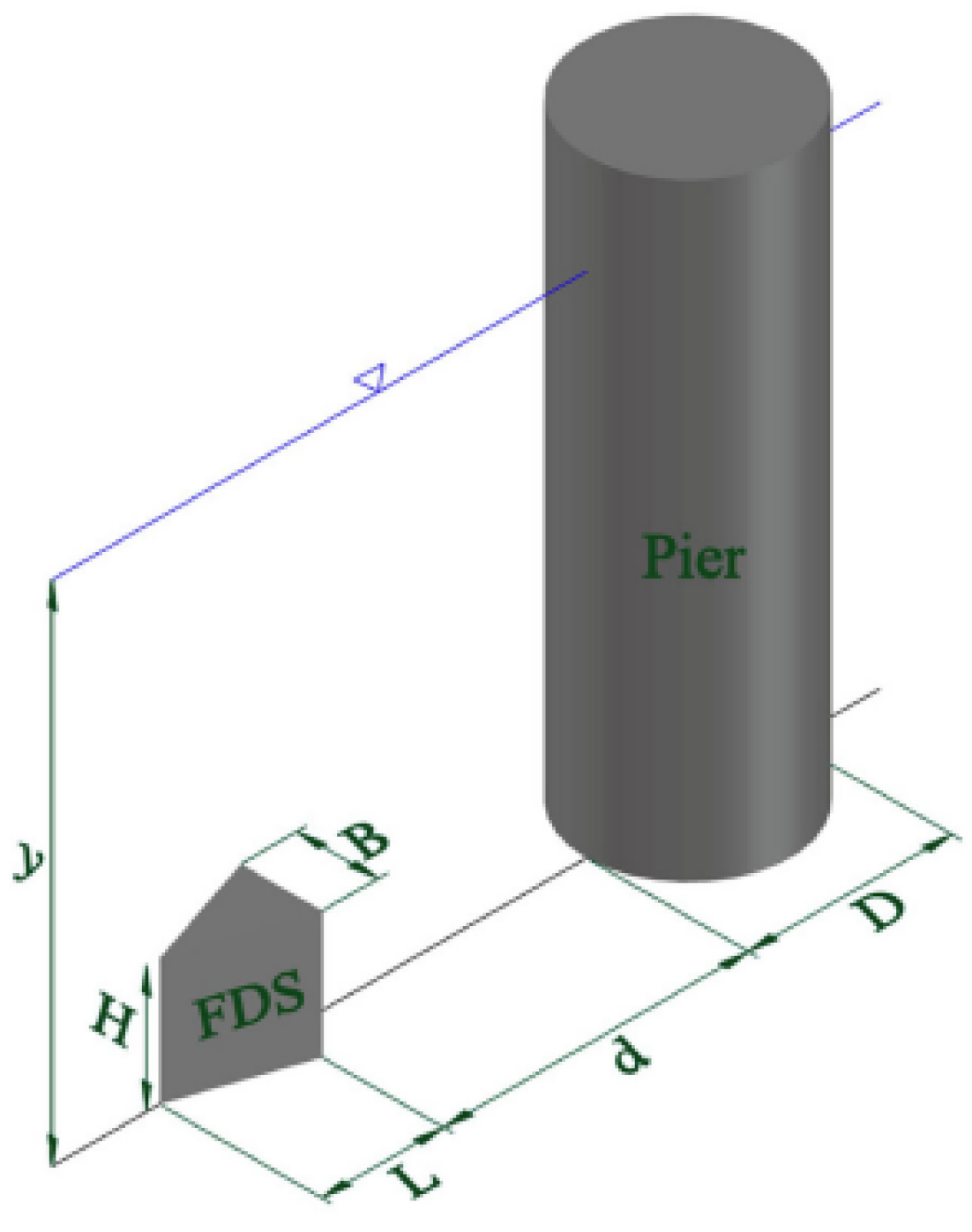
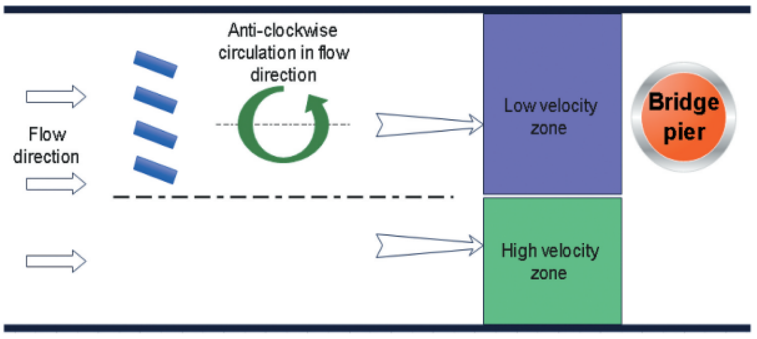
The arrangement of the deflector scheme is presented in
Figure 30. The scheme operates by inducing secondary circulation in the deflector region, thereby altering the magnitude and direction of bed shear stress in the surrounding area. Consequently, the flow velocity distribution and sediment transport rate are modified. Odgaard and Kennedy [
73] introduced the application of deflectors on sand beds to mitigate and control scour. Their investigations revealed that deflectors induced changes in the flow field, leading to alterations in bed shear stress magnitude and direction, subsequently influencing sediment transport patterns. Chauhan et al. [
74] comprehensively elucidated the mechanism underlying deflector implementation for scour protection. They emphasized that during flood periods, bridges are susceptible to severe scour-related issues. Placing deflectors upstream of the structure generates a vortex at the rear, while downstream flow establishes a vertical shear layer. These combined effects reduce flow velocity ahead of the pile by mitigating the pressure gradient, thereby modifying sediment transport and diminishing scour.
Tafarojnoruz [
21] highlighted key control parameters for the deflector scheme, including blade height (
), height-to-length ratio (
, where
denotes blade length), and entry angle (
). Lauchlan et al. [
21,
94] contended that when the aspect ratio
, the deflector’s influence on sediment transport surpasses its impact on the flow field, akin to sacrificial piles. Lauchlan et al. [
94] further observed that the most effective scour protection is achieved with
, resulting in a 34 % reduction in maximum scour depth and a 50% decrease in scour volume. Tafarojnoruz [
21] concluded, based on extensive experiments, that the deflector can reduce maximum scour depth by 50% under both clear water and dynamic bed scour conditions. Ghorbani et al. [
57] demonstrated that flow velocity oscillations and dynamic bed scour diminish the deflector scheme’s scour protection capabilities and overall effectiveness. In their comparative analysis, Ghorbani et al. found that the double-bladed deflector outperformed the single-bladed deflector in reducing scour. Vaghefi et al. [
75,
76] substantiated the scour protection effect of deflectors through experimental investigations in river bend sections. For group pile structures comprising three piles, the maximum scour depth was reduced by 35%. In single pile experiments, the maximum scour depth diminished by 46%, thus illustrating the deflector’s effectiveness in large river bends.
Sand barriers are commonly employed in river management to prevent the undercutting of river beds. By limiting sediment transport, they effectively influence bed dynamics and reduce scour [
77,
78,
79]. Grimaldi et al. [
80] implemented a sand barrier downstream of a pile structure to control scour under constant flow conditions, as illustrated in
Figure 31. The most significant reduction in scour depth, amounting to 26%, was achieved when the sand barrier was placed immediately downstream of the pile structure. However, arranging the sand barrier at a position of 0.5
D downstream of the pile structure resulted in reductions of over 80% in both scouring range and volume of scoured sediment, demonstrating the most comprehensive effectiveness. Liang et al. [
44] conducted experiments involving current and unidirectional wave conditions, yielding scour depth reduction rates (
) of 42.6% and 13.6%, respectively, compared to a control group without any protection scheme. Tafarojnoruz et al. [
45] observed a maximum scour depth reduction rate (
) of 17.2% for a sand barrier scheme under the influence of current. According to the existing literature [
45,
80,
81,
82], it is generally believed that placing the sand barrier in close proximity to the downstream surface of the pile structure effectively reduces scour behind the pile, while the presence of scour behind the sand barrier is not prominent. Aysar [
81] experimentally concluded that the relative position of the sand barrier behind the pile structure plays a crucial role in reducing scour depth and is a significant factor affecting scour protection capacity. The best protection effect is achieved when the relative position (
) is 0 to 0.32 times the pile diameter behind the pile. For relative flow velocities (
) of 0.48, 0.64, 0.8, and 0.96, the scour reduction rates are 16%, 30%, 23%, and 28% when
, and 12%, 28%, 17%, and 25% when
, respectively. The flow rate also influences the scour protection effectiveness of the sand barrier scheme.
The sand barrier can be used in combination with other forms of scour protection schemes [
79]. In the experiments of Gaudio et al. [
47], the best scour reduction rate is 25.3% for the combined scheme of sand barrier and deflector blade and the reduction is 63.3% for the combined scheme with horizontal plate. The authors concluded that there is an improvement compared with the maximum scour depth reduction rate of 17.2% in the Tafarojnoruz et al. [
45] experiment.
4.4. Pile Alteration Scheme
The pile alteration scheme is mainly used to reduce the obstruction of incoming flow by changing the shape of the structure or the foundation of the structure. It can reduce the flow velocity and pressure in the local area of high flow velocity and high pressure, to reduce the bed shear stress, and thus to achieve the effect of reducing scouring.
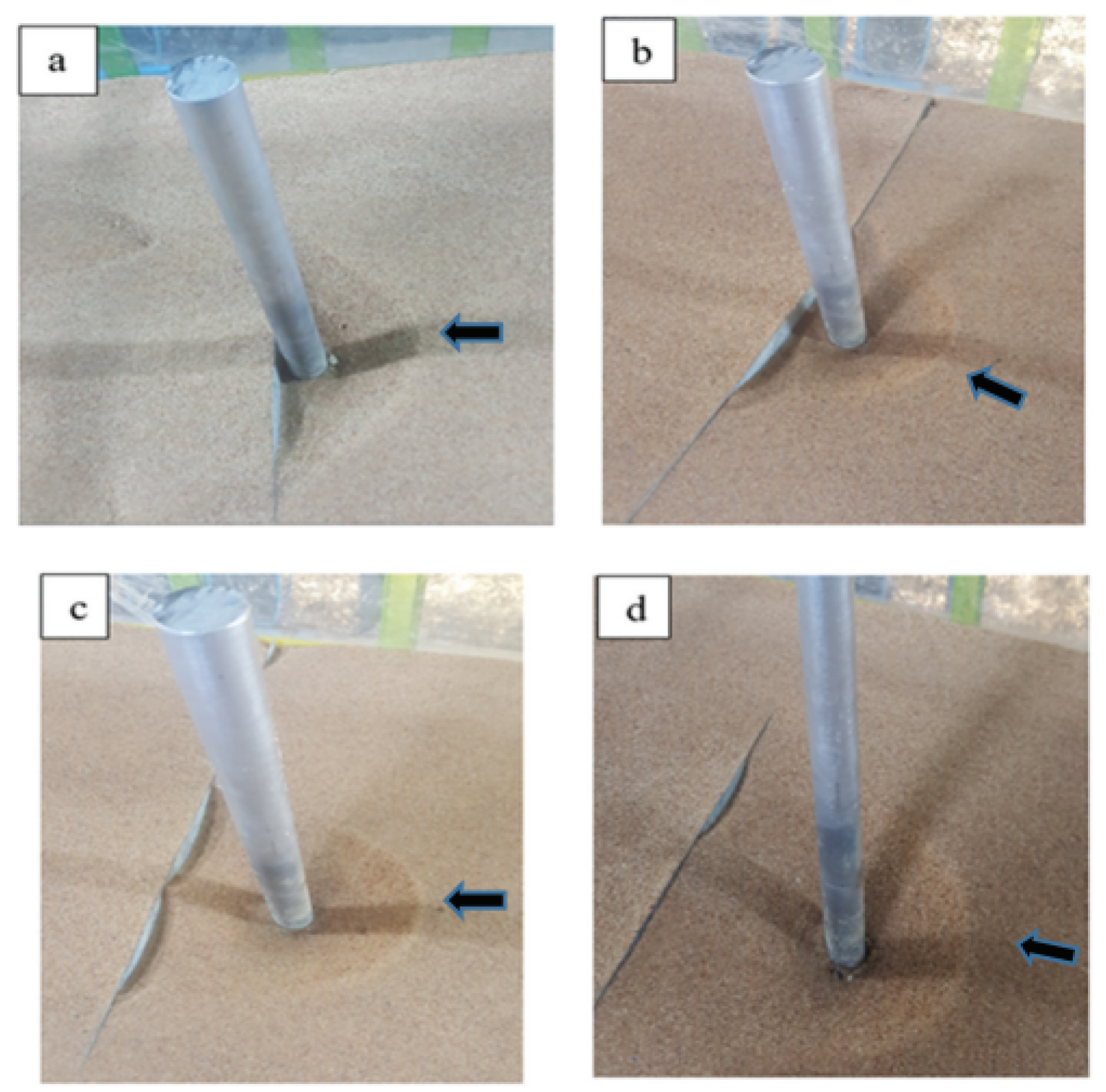
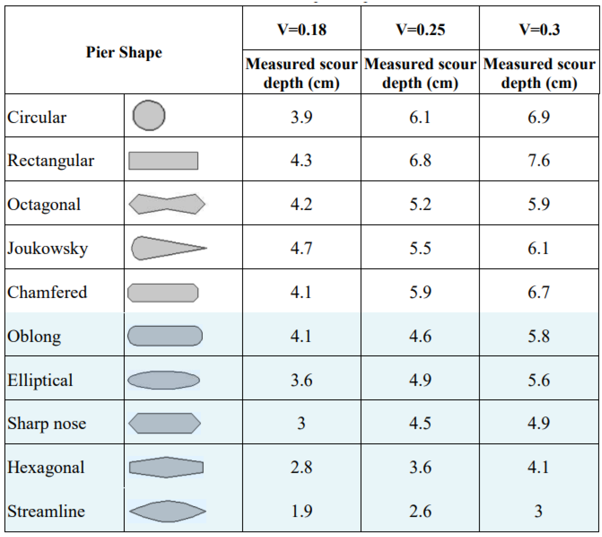
Al-Shukur et al. [
83] illustrated the effect of pile type change on local scouring, as shown in
Figure 32. In the experiment, the structure with rectangular pile type has the largest local scour depth, and the maximum scour depth is larger in comparison with other pile types at three different velocity. The structure with cylindrical pile type also has a larger scour depth, and the structure with streamlined pile type has the smallest maximum scour depth, indicating that pile type change can make the structure with a better scour protection effect. In the experiment of Farooq et al. [
84], the maximum scour depths of six pile-type structures were compared, and it was found that the maximum scour depths of round, diamond, pointed-nose, octagonal, and elliptical structures were reduced by 17.7%, 22.4%, 10.4%, and 15.1%, respectively, compared with those of rectangular pile-type structures. Consistent conclusions were also reached in the experiments of Baranwal et al. [
85].
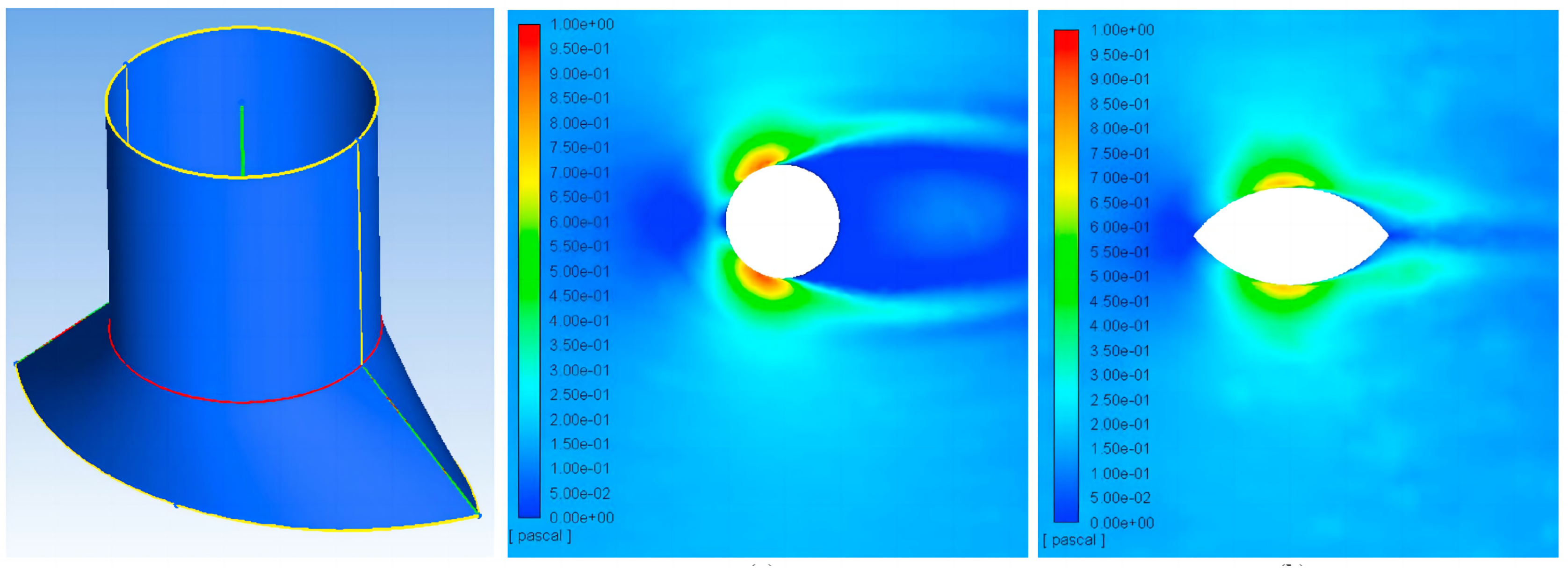
Aly et al. [
11] designed a streamlined extended foundation as shown in
Figure 33. Aly et al. calculated the different hydrodynamic characteristics of the circular and streamlined foundations at the same inlet velocity by means of computational fluid dynamics (CFD). The results show that the near-bottom shear stress around the pile perimeter of the cylindrical structure is about 1 Pa and the flow velocity is 0.5 m/s, while the near-bottom shear stress around the pile perimeter of the streamlined foundation is 0.8 Pa and the flow velocity is 0.45 m/s. Compared with the streamlined foundation, the shear stress of the cylindrical foundation is greater and the flow velocity is smaller. The authors concluded that under the shear stress, the cylindrical structure is more prone to sediment initiation and transport in the 45
° angle direction on both sides, while in contrast for the streamlined foundation, only sediment with smaller particle size can be eroded and transported along the streamlined foundation. Aly et al. [
11] concluded that this can prove that streamlined foundations have better scour protection effect compared to cylindrical foundations.
For multi-pile bearing structures, it has been found that changing the relative position of the bearing can achieve the effect of scour protection. Yang et al. [
95] found that in this type of pile foundation structure, burying the bearing-structure under the bed would have a better scour protection effect. The scour pattern of this form of group pile structure depends strongly on the flow type, with different erosion topography under wave–flow coaction, pure current action and pure wave action, and the scour intensity under wave–flow coaction and current action is greater than that under wave action. Under wave action, the scour of this multi-pile bearing is influenced by the angle of incoming flow, which causes a larger scour range when the incoming flow faces the sharp angle of the bearing.


 ,
, 


