Article

Buckling Behavior of Stainless Wave-Shaped Pressure Hulls

1
School of Mechanical Engineering, Jiangsu University of Science and Technology, Zhenjiang 212003, China
2
China Ship Scientific Research Center, Wuxi 214082, China
*
Authors to whom correspondence should be addressed.
J. Mar. Sci. Eng. 2024, 12(5), 821; https://doi.org/10.3390/jmse12050821
Submission received: 23 April 2024 / Revised: 11 May 2024 / Accepted: 12 May 2024 / Published: 14 May 2024
(This article belongs to the Section Ocean Engineering)

Abstract

:
This study primarily focuses on the buckling behavior of wave-shaped pressure hulls subjected to uniform external pressure. The effect of slant angle on the buckling behavior of hulls was examined. The tested slant angles ranged from 0° to 30° and were increased at 1° increments. The buckling of smooth cylindrical pressure hulls and wave-shaped pressure hulls was investigated using numerical methods. A wave-shaped pressure hull was produced for experimental verification. The nonlinear numerical results aligned with the collected experimental data. The buckling load of the tested wave-shaped pressure hull was approximately 1.87 times that of the equivalent cylindrical pressure hull. Furthermore, a formula was developed to estimate the load-bearing capacity of the wave-shaped pressure hull. This formula, which has been experimentally validated, comprises a correction coefficient (obtained through numerical evaluation and regression analysis) and a classic semi-analytical formula for cylindrical pressure hulls.

1. Introduction

In recent years, cylindrical pressure shells have attracted considerable attention in the fields of marine engineering and deep-sea exploration because of their efficient spatial utilization and straightforward geometric configuration. Such shells are widely used in underwater pressure hulls, such as submarines, submersibles, and torpedoes [1,2,3,4,5]. However, such pressure hulls are prone to buckling under uniform external pressure because of factors such as reduced wall thickness and geometric defects [6,7,8,9].
An effective buckling prevention strategy is to enhance the stiffness of a shell by adding rings [10,11], stringers [12,13], or corrugations [14,15,16,17] (Figure 1). This strategy is applicable not only to pressure shells but also to the seismic protection of walls [18]. Cho et al. examined the stability and failure modes of ring-stiffened steel cylinders under external hydrostatic pressure and identified multiple failure modes to provide novel insights into the structural integrity of such cylinders in the context of marine and naval engineering [19,20]. Do et al. studied the collision responses of steel stringer-stiffened cylinders and performed hydrostatic pressure tests to characterize the ultimate strengths in damaged and intact conditions. Their results revealed that collision damage had a minimal effect on the ultimate strength of stringer-reinforced cylinders [13]. Ghazijahani et al. investigated the buckling behavior of thin cylindrical shells reinforced with circumferential corrugations subjected to uniform external pressure. They compared experimental results with theoretical predictions to demonstrate that corrugation improves the buckling stability of such structures. In another study, the same research group revealed that corrugation considerably enhances buckling strength and failure capacity and that the number of corrugations influences the rigidity and behavior of shells [21,22]. Ross and colleagues conducted an experimental and numerical study on corrugated cylinders and developed design charts for predicting the plastic collapse of such cylinders by applying a semi-empirical method. The collapse pressure of the tested cylinders was calculated by obtaining the theoretical instability pressure of an ideal cylinder on the basis of design charts [14,23]. Among the buckling prevention strategies that have been employed, corrugation appears to be the most promising and effective and does not require additional stiffeners. However, the production of high-precision, large corrugated pressure shells is challenging because of limitations pertaining to materials and molding tools.
The rotational pressure shell comprising several large periodic-wave segments can overcome the aforementioned challenge. When the focus is on a relatively small number of relatively large wave segments, the overall precision and structural integrity of a pressure shell can be maintained. Ross proposed a specialized rotational pressure shell consisting of several large cones. Through the application of numerical tools, one study discovered that the linear buckling load of this type of shell is 2.1 to 2.3 times greater than that of a smooth cylindrical pressure shell [23]. Zhang et al. reported similar results; they fabricated rotational pressure hulls composed of four identical cones and examined the effect of slant angle on the linear and nonlinear buckling loads of cone-segmented pressure hulls [24]. Ultimately, they confirmed that rotational pressure hulls with large periodic-wave segments exhibit excellent load-bearing capacity. However, their cone-segmented pressure hulls could not smoothly transition at junctions, resulting in an inefficient use of internal space. Furthermore, an abrupt geometric change at a connection point resulted in stress concentration. Therefore, this study focused on the buckling behavior of wave-shaped pressure hulls with four cones and three cylinders while they are being subjected to uniform external pressure.

2. Materials and Methods

2.1. Problem Identification

Consider a wave-shaped pressure hull with four cones and three cylinders enclosed by two thick plates. The closed capacity (V) of such a hull is identical to that of the cylindrical pressure hull examined in another study [24]. As displayed in Figure 2, the aforementioned wave-shaped pressure hull features a short base radius (r), a long base radius (R), a slant angle of α = sin−1(R/hr/h), and a wall thickness (t). The plates have a thickness of T and a diameter of D = 2R. A single cone and a cylinder have the same generatrix length (h). The wave-shaped pressure hull has a total length of H = 4hcosα + 3h. Accordingly, the closed capacity (V) of the wave-shaped pressure hull can be mathematically expressed as follows:
V = 4 3 π h ( ( R h sin α ) 2 + R 2 + R ( R h sin α ) ) cos α + π R 2 h + 2 π ( R h sin α ) 2 h .
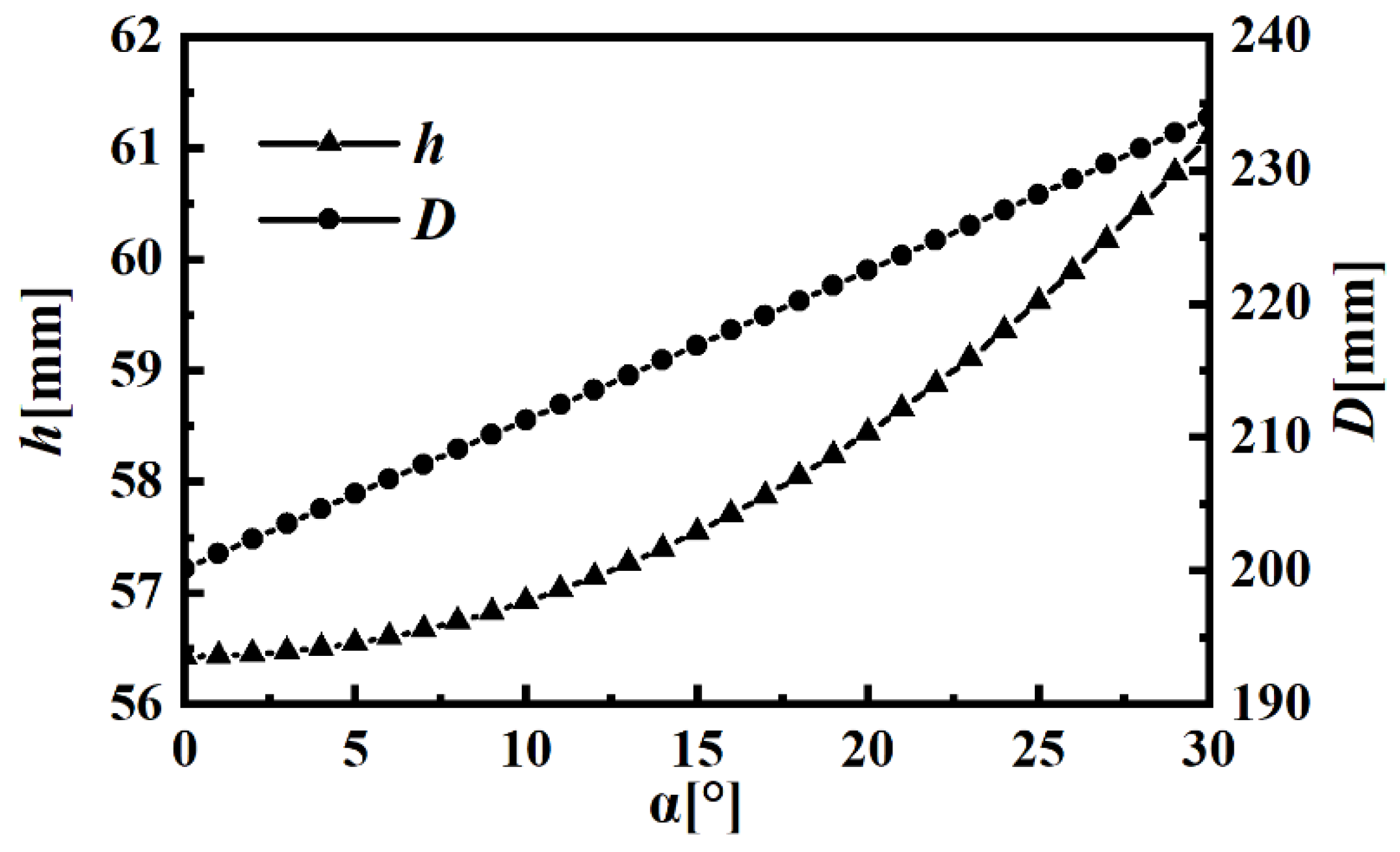
To investigate the influence of the slant angle on the geometrical and mechanical properties of wave-shaped pressure hulls, wave-shaped pressure hulls with slant angles between 0° and 30° were tested at intervals of 1°. In other words, 30 wave-shaped pressure hulls and one cylindrical pressure hull were investigated in this study, given that a cylindrical pressure hull can be regarded as a wave-shaped pressure hull with a slant angle of α = 0°. Table 1 presents the constant parameters characterizing the analyzed pressure hulls. The dimensions H, t, T, and V remained constant across all the wave-shaped pressure hulls. The thickness (T) of the plates was approximately 28 times the thickness (t) of the pressure hull walls, resulting in rigid closure. The generatrix length (h) and diameter (D) for multiple slant angles were determined using Equation (1). Detailed data are shown in Figure 3; the results indicated that the length and diameter increased with the slant angle, suggesting an increase in the material for manufacturing the pressure hull.

2.2. Numerical Methods

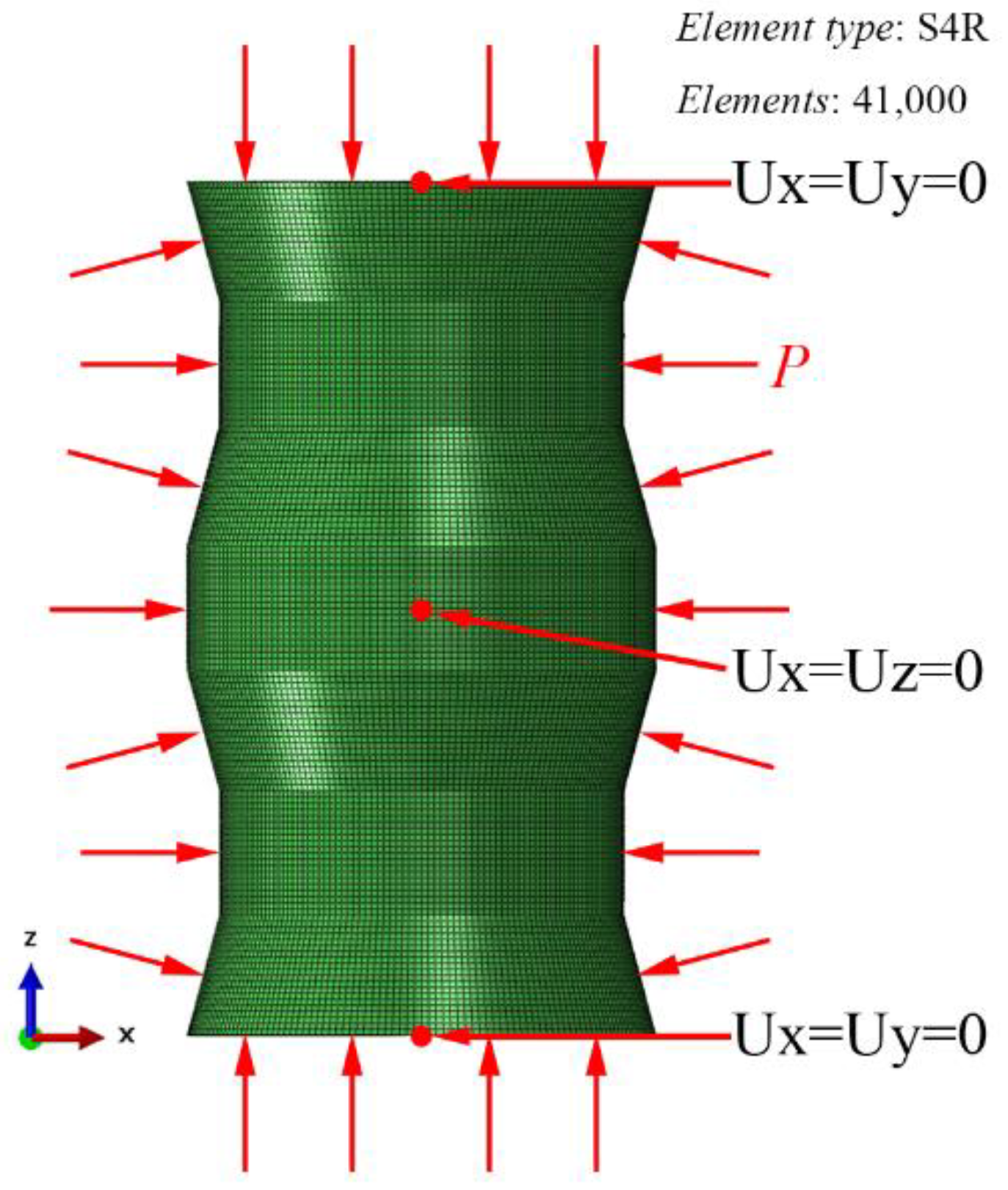
Numerical simulations of 31 pressure hulls were conducted using Abaqus [25]. The representative numerical models applied in this study are depicted in Figure 4. Linear and nonlinear buckling behaviors were extracted from the results of numerical assessments. The considered linear behaviors included the lowest eigenvalues and corresponding eigenmodes, and the nonlinear behaviors included critical buckling loads, equilibrium paths, and post-buckling modes.
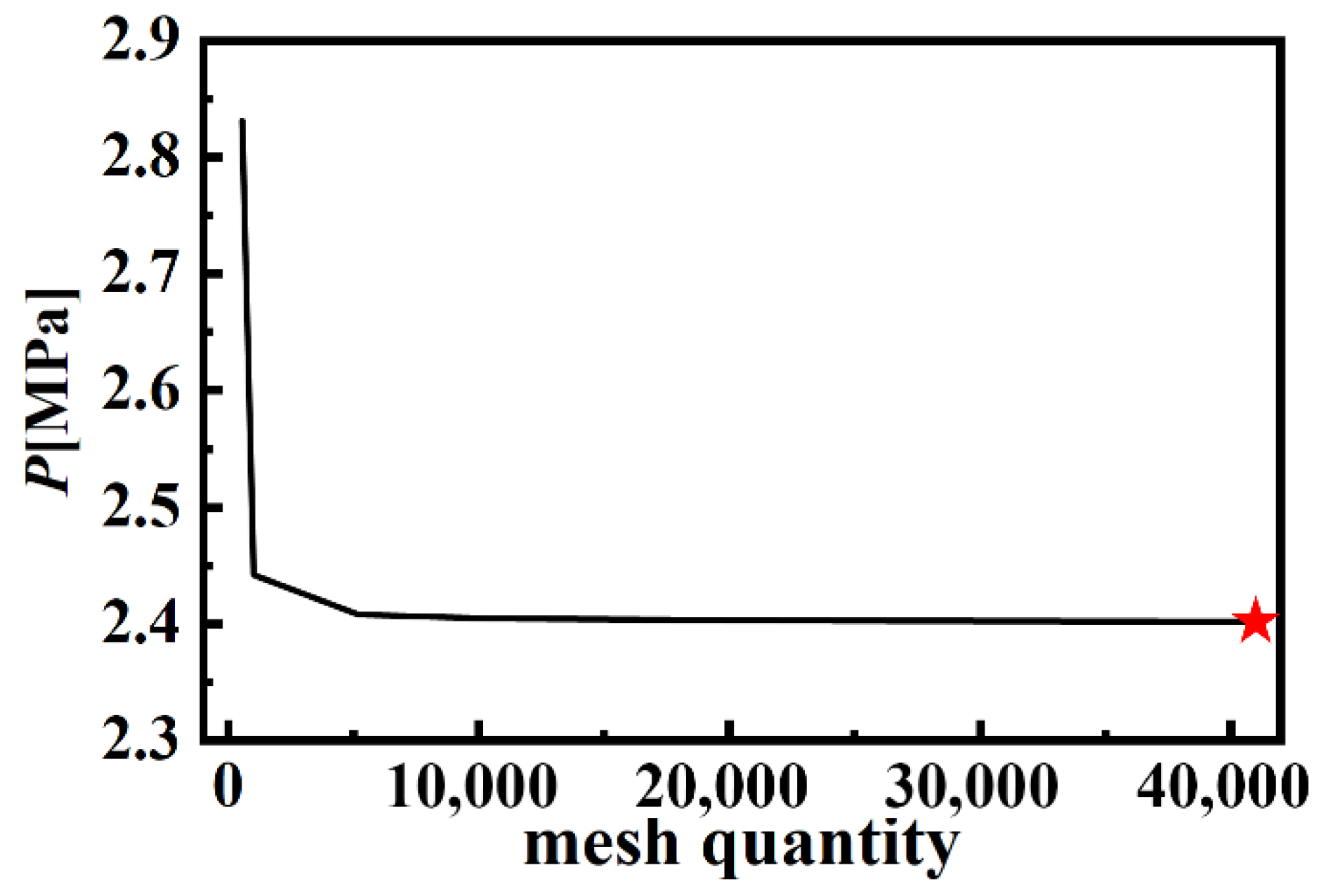
Finite element analysis was conducted using four-node shell elements (S4R) with six degrees of freedom. S4R provides solutions for shell problems that are comprehensively described by the classic Kirchhoff shell theory, with bending strains approximated according to the Koiter–Sanders shell theory [26]. As displayed in Figure 5, convergence studies based on linear analysis revealed that a finite element model comprising 41,000 elements was sufficient. In this study, the nominal section thicknesses (Table 1) of the shells and plates were set inward and outward, respectively. Five points for integration over thickness were selected. The elastic–plastic material modeling performed in this study can be expressed as follows:
σ = E ε   , σ   σ y σ y + K ε , σ >   σ y .
The present material properties are described as follows: Young’s modulus E = 198.4 GPa; Poisson’s ratio ν = 0.3; yield stress σy = 275 MPa; hardening coefficient K = 1140 MPa. The identified bilinear elastic–plastic relationship was consistent with that presented in another study [24].
The three nodes of each finite element model were uniformly constrained to counteract additional reactive forces and to prevent rigid body motion. Specifically, Ux = Uy = 0 for the centers of the top and bottom plates, and Ux = Uz = 0 for the middle node of a shell. This boundary condition, recommended by the China Classification Society (CCS) Rules for the Classification and Construction of Diving Systems and Submersibles, can be applied to numerically evaluate the ultimate strength of spherical and cylindrical pressure hulls [27]. Furthermore, this boundary condition has been applied to effectively evaluate the ultimate strength of egg-shaped pressure hulls [28,29,30], longan-shaped pressure hulls [31], and corrugated pressure hulls [17].
A unit load of 1 MPa was applied to the outer surface of the finite element model. The lowest eigenvalue obtained was multiplied by the unit load that was equal to the linear buckling load, and the highest load factor obtained was multiplied by the unit load that was equal to the nonlinear buckling load. The subspace algorithm was selected for linear buckling analysis; the number of eigenvalues to be estimated was set to 6, with a maximum of 3000 iterations. The modified Riks method was employed for nonlinear buckling analysis, the initial increment of the arc length was set to 0.01 (total arc length scale factor = 1), the minimum arc length increment was 10−50, and the maximum arc length increment was 0.02.

2.3. Experimental Methods

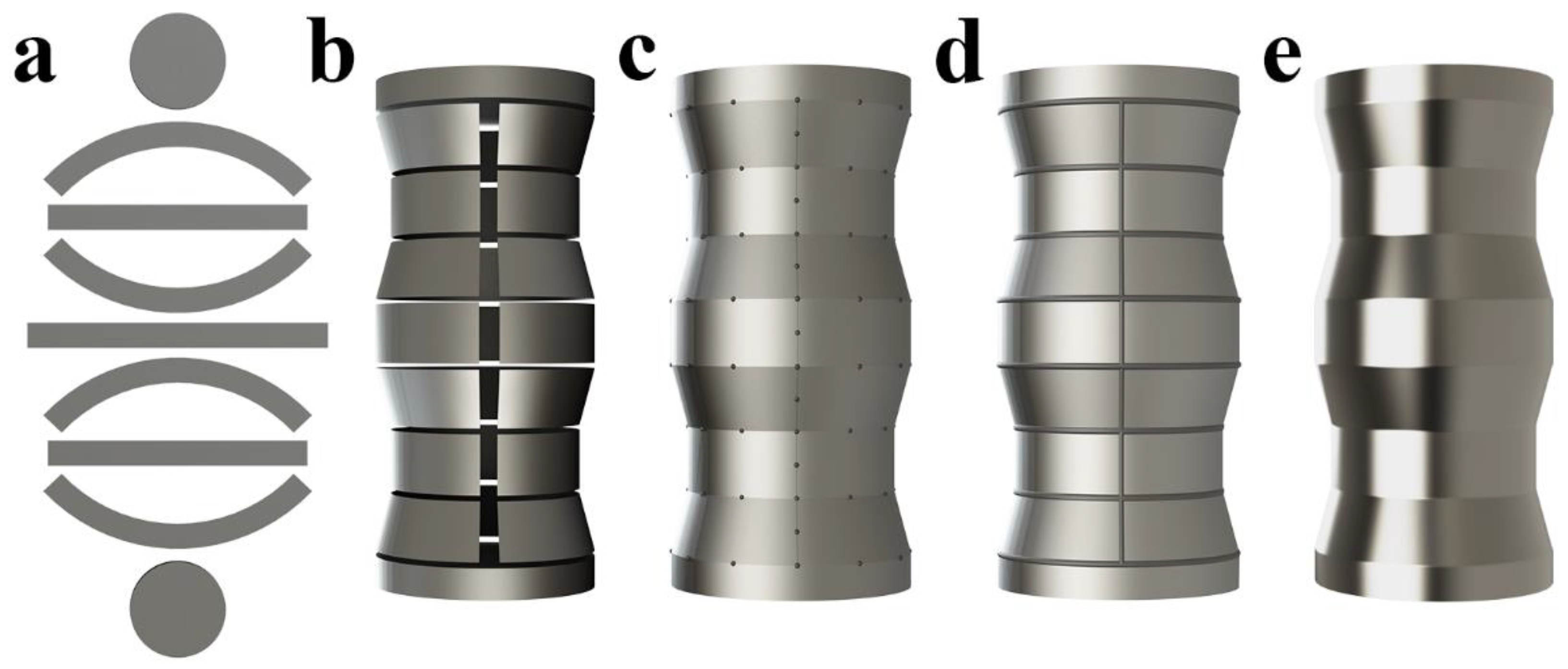
A wave-shaped pressure hull was fabricated from a thin stainless plate. This fabrication process involved laser blanking, manual bending, spot weld assembly, preform welding, and external surface smoothing (Figure 6). First, four arc-shaped plates and three rectangular plates were blanked from a 1.074 mm thick stainless sheet through computer numerical control (CNC) laser cutting. In addition, two circular plates were cut from a 30 mm thick steel plate. The dimensions of these plates were calculated using the data presented in Figure 2 and Figure 3 and Table 1. Second, a numerically controlled roller machine was used to roll-bend each arc-shaped or rectangular plate into a cone or cylinder. Third, four bent cones, three cylinders, and two plates were preliminarily assembled into a preform through spot welding. Fourth, the assembled preform was closed through manual welding. Finally, manual polishing was performed on the closed preform to remove welds and ensure a smooth external surface. Notably, because of the thin-walled structure of the fabricated items, stress relief was not required after fabrication.
After fabrication, the external geometries and wall thicknesses of the fabricated wave-shaped preform were measured to confirm the accuracy of the fabrication process. The external geometry of the fabricated wave-shaped preform was optically measured using an optical three-dimensional scanner (EinScan HX; SHINING 3D, Hangzhou, China) with a measurement accuracy level of approximately 0.04 mm (Figure 7a). Before scanning, marking stickers were evenly and randomly affixed to the shell of the preform. At least three marking stickers were required for stitching in the common areas. During the affixing process, an essential step was ensuring that the marking stickers were visible within the camera’s field of view at a working distance. The optical scanner automatically stores point cloud data to generate the geometric model of a preform surface.
After geometric scanning, all marking stickers were removed, and the surface of the preform was cleaned with ethanol. The measurement points were the intersections of 28 equidistant meridians and 12 equidistant circumferential lines; that is, thickness measurements were taken at 336 points (Figure 7b). The thickness of the fabricated wave-shaped preform was measured using an ultrasonic non-destructive thickness meter (DAKOTA/PX-7; Sonatest Corporation, Milton Keynes, UK). The thickness of the welds was not measured because the randomly distributed geometry could have led to measurement deviations.
After the thickness of the fabricated wave-shaped preform was measured, the preform was subjected to hydrostatic testing within a pressure tank (Figure 7c). The internal radius and height of the pressure tank were 250 and 500 mm, respectively. The pressure tank had a wall thickness of 30 mm and was designed to operate at a maximum operational pressure of 8 MPa. A digital pressure sensor was mounted on the tank cover to record the pressure inside the tank. Pressure data were recorded using a dynamic data acquisition system (DH5902N, DongHua, Jingjiang, China) at a sampling frequency of 50 Hz to ensure accurate and real-time monitoring of pressure variations during the testing process. Pressure was incrementally applied using a hand-operated pressure pump to establish quasi-static loading conditions. Tap water served as the pressure medium. A rapid decrease in pressure and audible noise indicated that the fabricated wave-shaped preform was buckling.

3. Numerical Results

This section describes a numerical investigation of the linear and nonlinear buckling behaviors of 30 wave-shaped pressure hulls and a cylindrical pressure hull. Finite element analyses were performed using Abaqus 2021 [25]. Apart from FEM, many other strong numerical methods can be potentially used, such as the Finite Difference Method [32], Bezier Multi-Step Method [33], and Differential Quadrature Method [34].

3.1. Linear Buckling Analysis

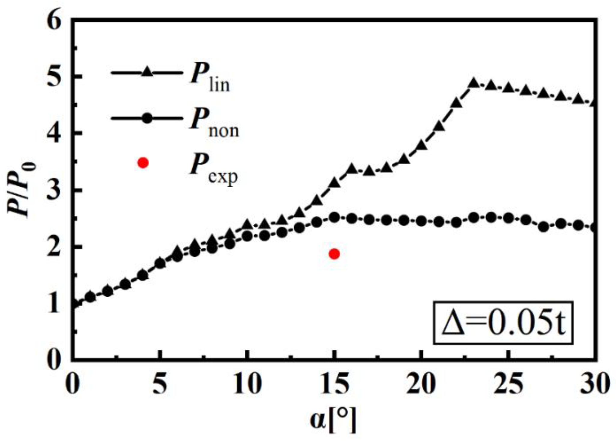
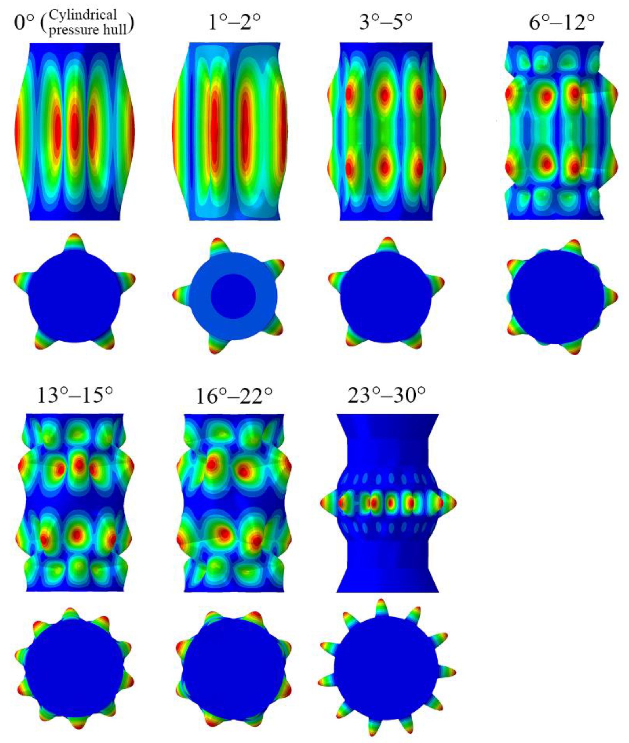
First, linear elastic eigenvalue analysis was conducted at multiple slant angles. The obtained linear buckling load is presented in Figure 8, and the obtained linear buckling mode is presented in Figure 9. When α < 23°, the linear buckling load increased with the slant angle; this increase can be attributed to the increased stiffness. A similar finding for corrugated pressure hulls was reported in another study [17]. At small slant angles, the linear buckling mode took the form of half a meridional wave and several circumferential waves located at the thinnest midpoint of each pressure hull. This buckling mode is a typical buckling mode of cylindrical pressure hulls. When the slant angle increased, the linear buckling location shifted from the midpoint to the two ends. Because of the rigid constraints of the plates, the amplitude of the end waves was substantially lower than that of the middle waves.
When α ≥ 23°, the linear buckling load tended to decrease considerably; this phenomenon was attributed to the reduced axial stiffness caused by excessive slant angles, resulting in a change in the buckling mode. The linear buckling loads of the wave-shaped pressure hull with α = 23° were up to 4.9 times greater than those of the equivalent cylindrical pressure hull, representing a considerable increase compared with the previously reported result for a cone-segmented pressure hull with a slant angle of 7° (i.e., the linear buckling load of the hull was 2.8 times that of the equivalent cylindrical pressure hull) [24]. Regarding α = 23° as an inflection point, after this point, the linear buckling location shifted again from the two ends to the midpoint.

3.2. Nonlinear Buckling Analysis

In the nonlinear modeling experiment conducted in this study, the linear buckling mode obtained through linear elastic eigenvalue analysis was defined as the initial geometric imperfection. This definition was established in accordance with the guidelines of the CCS (2018) and has been effectively applied in other studies [35,36,37,38]. The nonlinear buckling load that was numerically obtained when the imperfection size was 0.05 t is presented in Figure 8, which reveals that the nonlinear buckling load increased substantially when α < 15°. Notably, when α ≥ 15°, the nonlinear buckling load exhibited stability. However, both the linear and nonlinear buckling loads of the wave-shaped pressure hull with non-zero inclination angles were significantly higher than those of the equivalent cylindrical pressure hull, whether linear or nonlinear. Furthermore, because of material nonlinearity, the nonlinear buckling load was considerably lower than the linear buckling load.
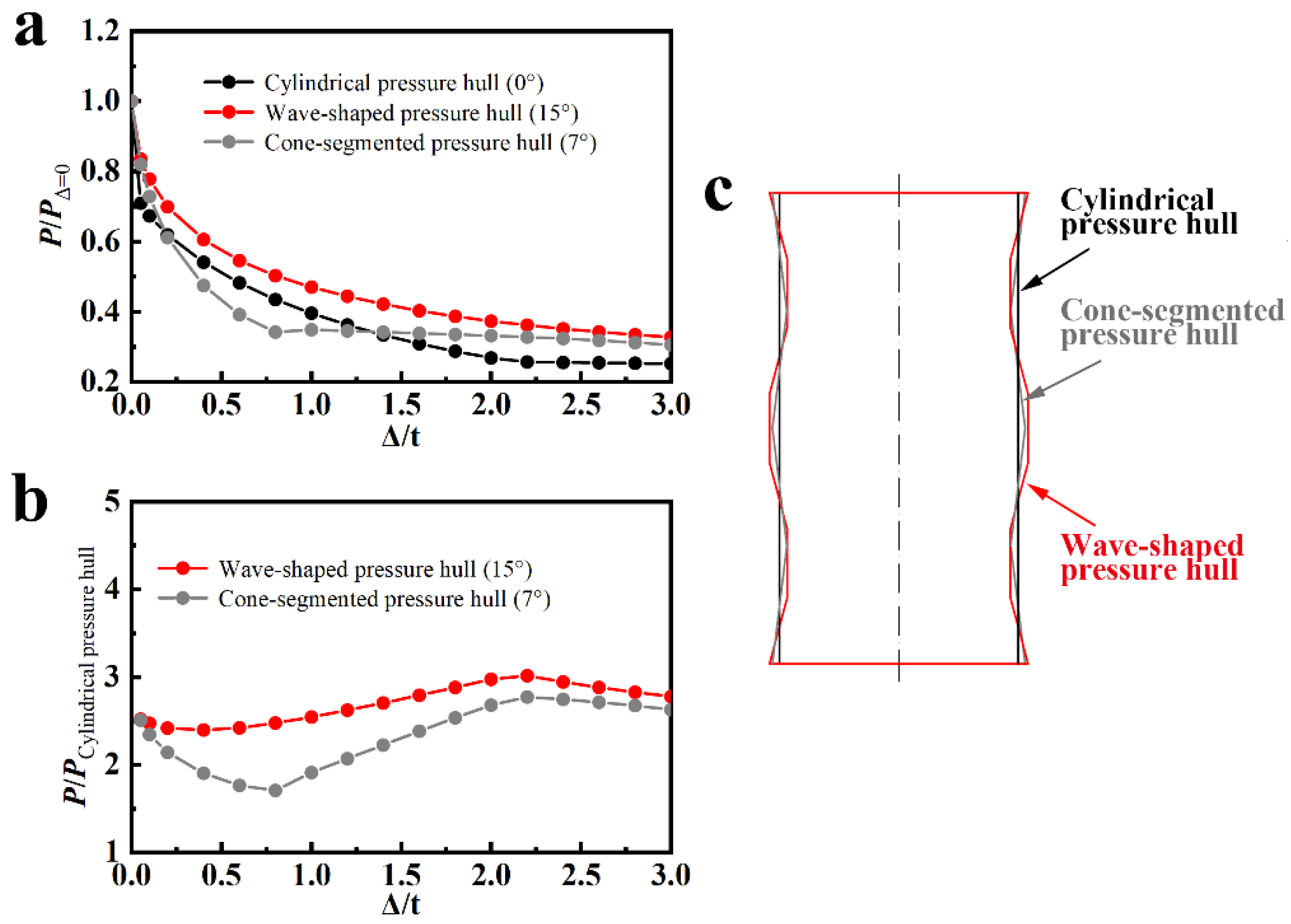
The optimal slant angle range for maximizing the hull’s nonlinear buckling load was determined to be 14° ≤ α ≤ 16°. Notably, slant angles exceeding 23° were nonoptimal because of severe stress concentration and the rapid decrease in axial stiffness resulting from an excessive incline. Therefore, the wave-shaped pressure hull with a slant angle of 15°, the equivalent cylindrical pressure hull, and the cone-segmented pressure hull with a slant angle of 7° [24] were selected to compare their sensitivity to imperfections. The contour profiles of these three pressure hulls are presented in Figure 10c. The obtained knockdown factors for the three pressure hulls, under the assumption that the imperfection amplitude range is 0–3 t, are presented in Figure 10a. The knockdown factor is defined as the ratio of the nonlinear buckling load for an imperfect geometry to the nonlinear buckling load for a perfect geometry [39,40,41]. A smaller knockdown factor was associated with higher sensitivity to imperfections.
In general, the wave-shaped pressure hull exhibited the most favorable performance with respect to imperfection sensitivity. As indicated in Figure 10a, when minor imperfections were present, the imperfection sensitivity levels of the three pressure hulls were similar; with moderate amplitude imperfections, the cone-segmented pressure hull exhibited the highest imperfection sensitivity; when major amplitude imperfections were present, the cylindrical pressure-resistant shell exhibited the highest imperfection sensitivity. Therefore, the wave-shaped pressure hull required lower manufacturing precision compared with the cone-segmented pressure hull. As indicated in Figure 10b, the nonlinear buckling loads of the wave-shaped pressure hull and cone-segmented pressure hull were normalized by the nonlinear buckling loads of the equivalent pressure hull at various imperfection amplitudes. The load-bearing capacity of the wave-shaped pressure hull was greater than that of the cone-segmented pressure hull, exhibiting a clear advantage in the presence of moderate amplitude imperfections.
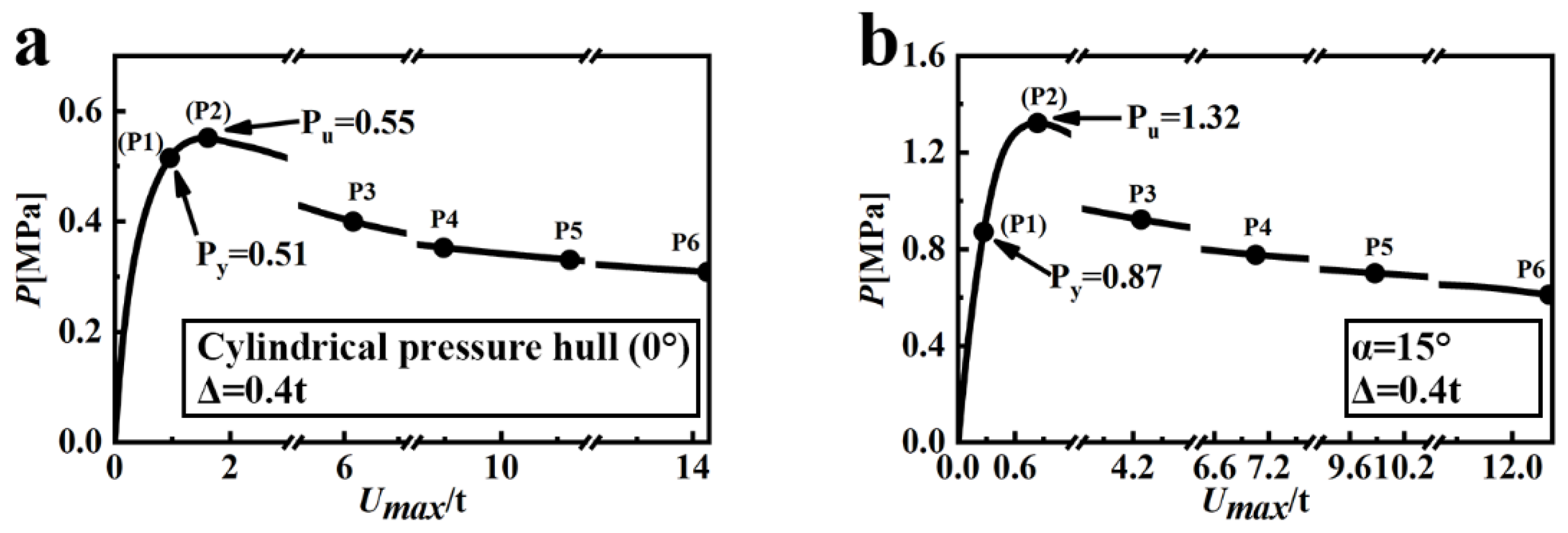
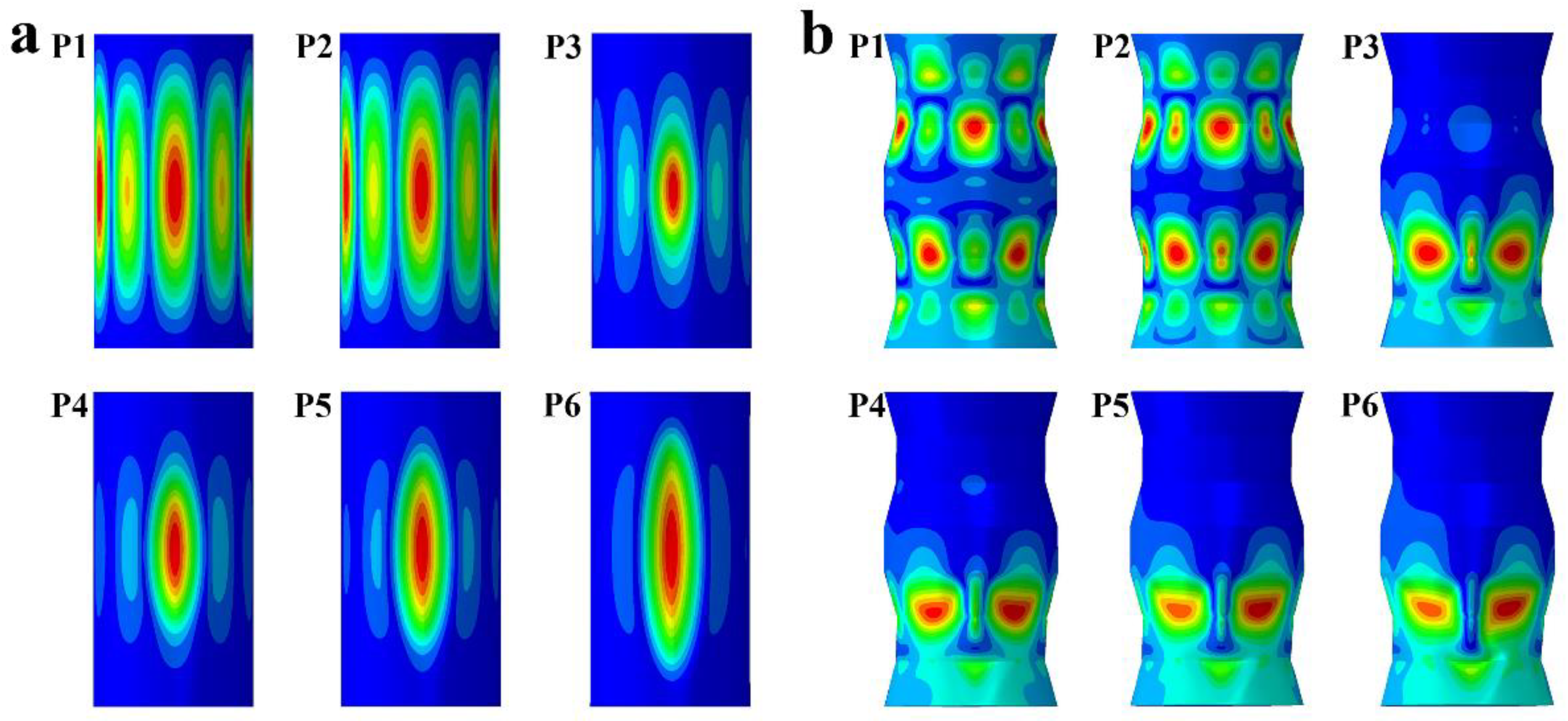
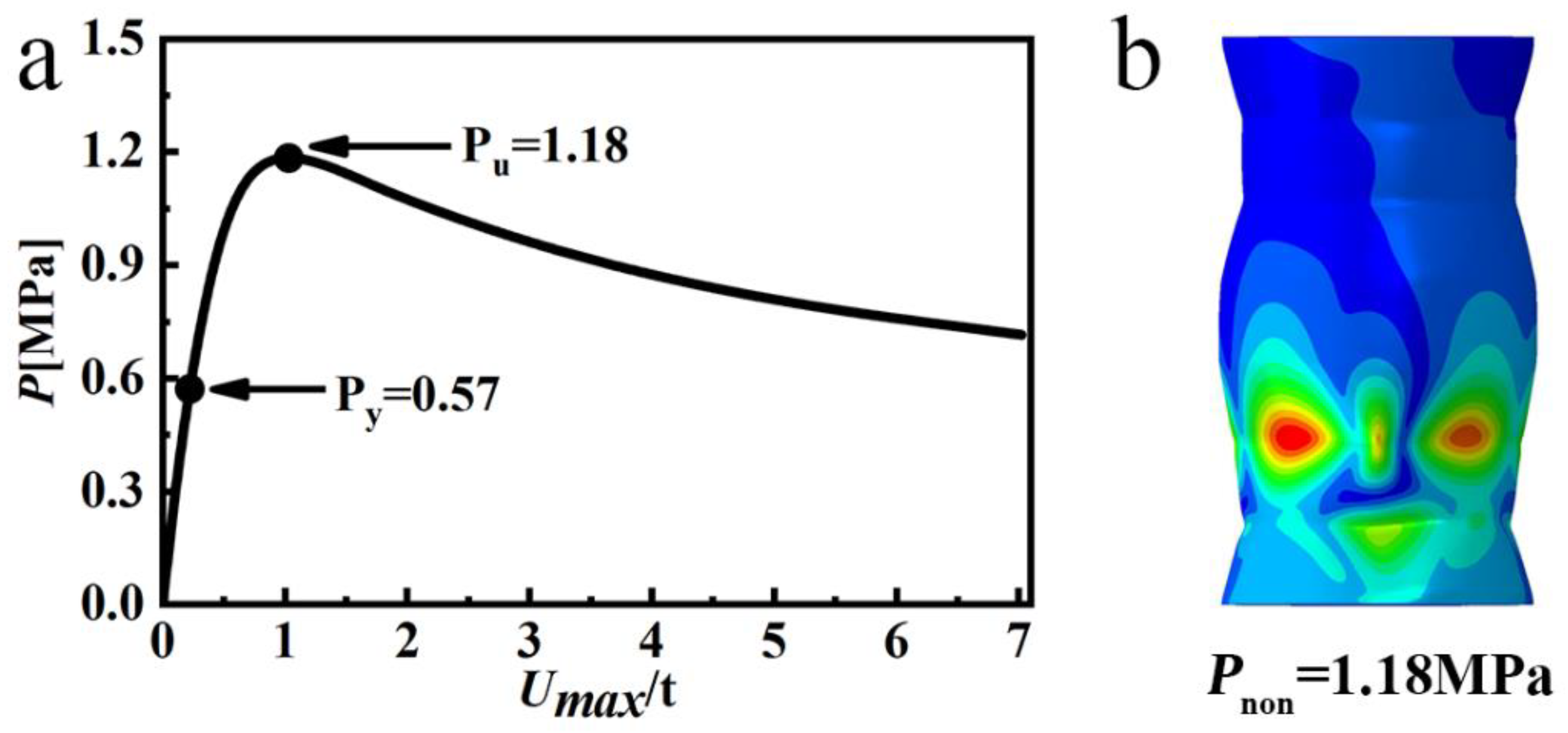
The equilibrium paths of the wave-shaped pressure hull and equivalent cylindrical pressure hull obtained through nonlinear Riks analysis are presented in Figure 11. Because the maximum deformation of the shell increased before its collapse, the applied pressure levels increased monotonically and nonlinearly. This pattern of pre-collapse behavior indicated that the shells underwent a markedly nonlinear collapse. The first yield load (P1) corresponded to the lowest applied pressure where the maximum equivalent stress in the pressure hull was equal to the yield point of the material. The first yield load also corresponded to local yielding and not to local buckling. The critical buckling load (P2) corresponded to the maximum load at which the pressure hulls buckled or lost stability. All yield points were identified in the pre-buckling stage, suggesting that material yielding occurred before buckling and confirming that the pressure hulls exhibited an elastic–plastic buckling regime. After the critical point was reached, the pressure hulls buckled and entered the post-buckling stage, during which the applied load substantially decreased as deformation increased. The final post-buckling mode of the pressure hull was characterized by local dimples. The buckling load of the wave-shaped pressure hull was approximately 2.4 times that of the cylindrical pressure hull. The deformation evolution of the pressure hulls at several typical loading points is presented in Figure 12. The pressure hulls initially exhibited uniform pre-buckling deformation in the circumferential direction because of their axisymmetric geometry, boundary conditions, and pressure loading. After the critical buckling point was reached, the pressure hulls exhibited nonuniform local post-buckling deformation due to instability.

4. Experimental Results

Numerical simulations were validated through experiments, where a wave-shaped pressure hull with an optimal slant angle of 15° was manufactured and underwent geometrical measurements and hydrostatic testing. The experimental, numerical, and semi-analytical results were consistent.

4.1. Analysis of Measurement Results

The geometric measurements of the fabricated wave-shaped preform indicated high fabrication accuracy. As indicated in Table 2, the fabricated wave-shaped preform had wall thicknesses of 1.008–1.098 mm and an average thickness of 1.074 mm, which was slightly lower than the average thickness (1.083 mm) of the cylindrical pressure hull tested in another study [24]. The standard deviation of the thickness of the fabricated wave-shaped preform was 0.016 mm, which was considerably higher than that of the aforementioned cylindrical pressure hull (0.003 mm). This difference was attributed to the cold bending process employed to produce the conical geometry and the necessity for additional welding. The measured surface area of the fabricated wave-shaped preform was 363,845 mm2, which closely approximated the nominal measurement of 360,774 mm2. Similarly, the measured volume of the fabricated wave-shaped preform was 14,581,047 mm3, which closely approximated the nominal measurement of 14,644,516 mm3. The differences between the fabricated and nominal geometries of the wave-shaped preform were only 1% and 0.4% for the external surface area and volume, respectively.
Figure 13 illustrates the contours that represent the geometric differences between the fabricated and nominal geometries of the pressure hull. Positive (negative) values correspond to outward (inward) deviations of the fabricated pressure hull from its nominal geometry, indicating localized convex (concave) imperfections. The geometric deviations in the fabricated wave-shaped pressure hull were primarily influenced by assembly tolerances, residual welding deformations, or weld seam grinding, with most deviations being concentrated at weld seams (Figure 13b). Figure 13 also indicates that the cylindrical pressure hull exhibited minor geometric deviations. These deviations, which were mainly due to bending errors in the cylinder, were primarily concentrated in the middle section of the cylindrical pressure hull. The comparisons presented in Table 2 and Figure 13 reveal that the manufacturing precision for the wave-shaped pressure hull was lower than that for the cylindrical pressure hull because of the additional assembly and welding required to fabricate the wave-shaped pressure hull.
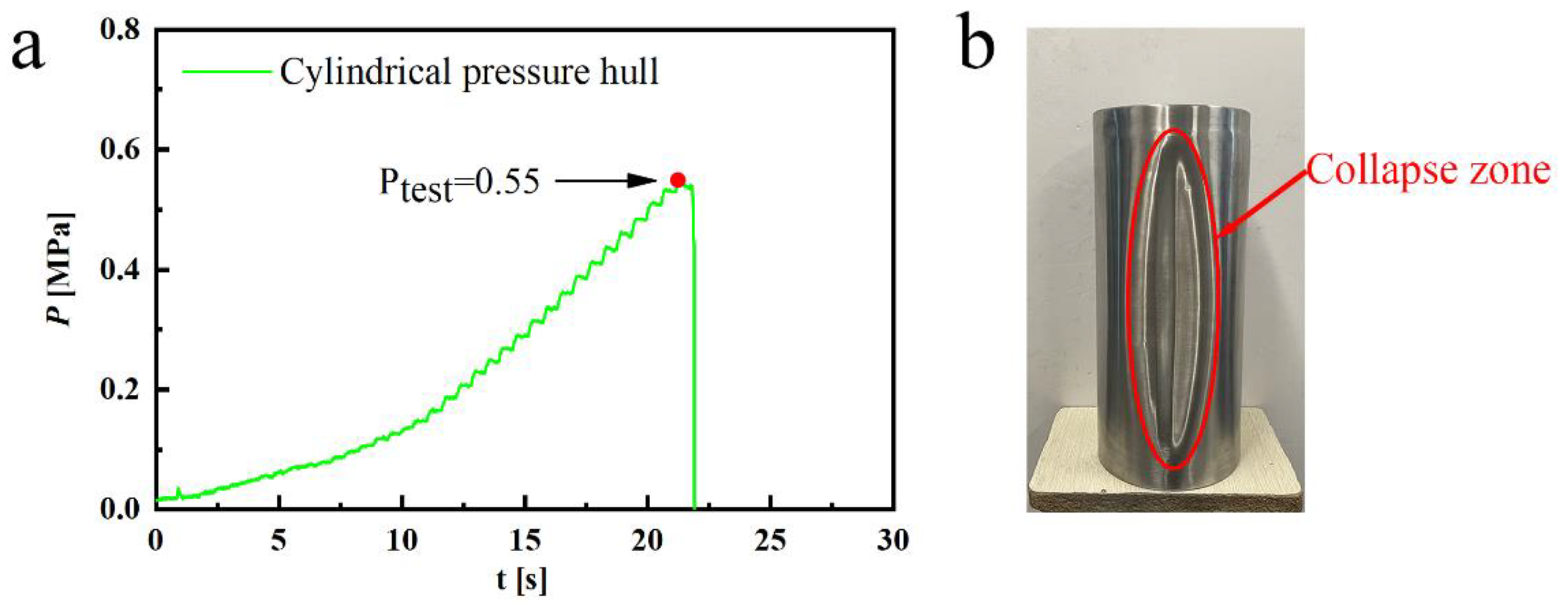
The post-buckling modes of all the tested pressure hulls were characterized by a local collapse resulting from major fabricated imperfections (Figure 14 and Figure 15). The buckling mode of the cylindrical pressure hull exhibited a single inward lobe, which was almost uniformly distributed across the entire shell. By contrast, the buckling of the wave-shaped pressure hull occurred at the lower end of the shell, specifically at the junction of two cones and a cylinder, manifesting as multiple minor collapses. These results indicate that the structure of the wave-shaped pressure hull significantly enhanced its stiffness, thereby effectively preventing buckling propagation. Such collapse modes are also reflected in the numerical observations presented in Figure 10.
Because the pressure pump used in this study was manually operated, the obtained pressure curves were step shaped, with each step corresponding to a small loading increment. The long loading time reflected by each curve indicated a quasi-static loading condition. The maximum recorded pressure in each curve corresponded to the buckling pressure of the hulls. The experimental buckling load for the cylindrical pressure hull was 0.55 MPa, which was considerably lower than that for the wave-shaped pressure hull (1.03 MPa). The load carrying capacity of the wave-shaped pressure hull was 87% greater than that of the cylindrical pressure hull; this outcome closely aligned with the numerical evaluation results (Figure 10). In addition, the experimental buckling load of the cylindrical pressure hull aligned with the numerical evaluation result (0.55 MPa; Figure 10). However, the experimental buckling load of the wave-shaped pressure hull was slightly lower than the numerical evaluation result (1.32 MPa) because of major geometric imperfections during the fabrication process.

4.2. Numerical Analysis of Fabricated Pressure Hulls

The FEM was employed to further examine the buckling of the experimental wave-shaped pressure hull. The simulation results for element meshing, element selection, pressure loading, boundary definition, material modeling, and model solving were consistent with the descriptions in Section 3.1 of this paper. The average wall thickness values based on the measurements presented in the fourth column of Table 2 were used for subsequent analyses. Linear and nonlinear analyses were performed on the fabricated wave-shaped pressure hull with real geometric imperfections. This numerical model was previously used in research conducted by the National Aeronautics and Space Administration [41,42,43]. The obtained numerical data are presented in Figure 16, Figure 17, Figure 18 and Figure 19.
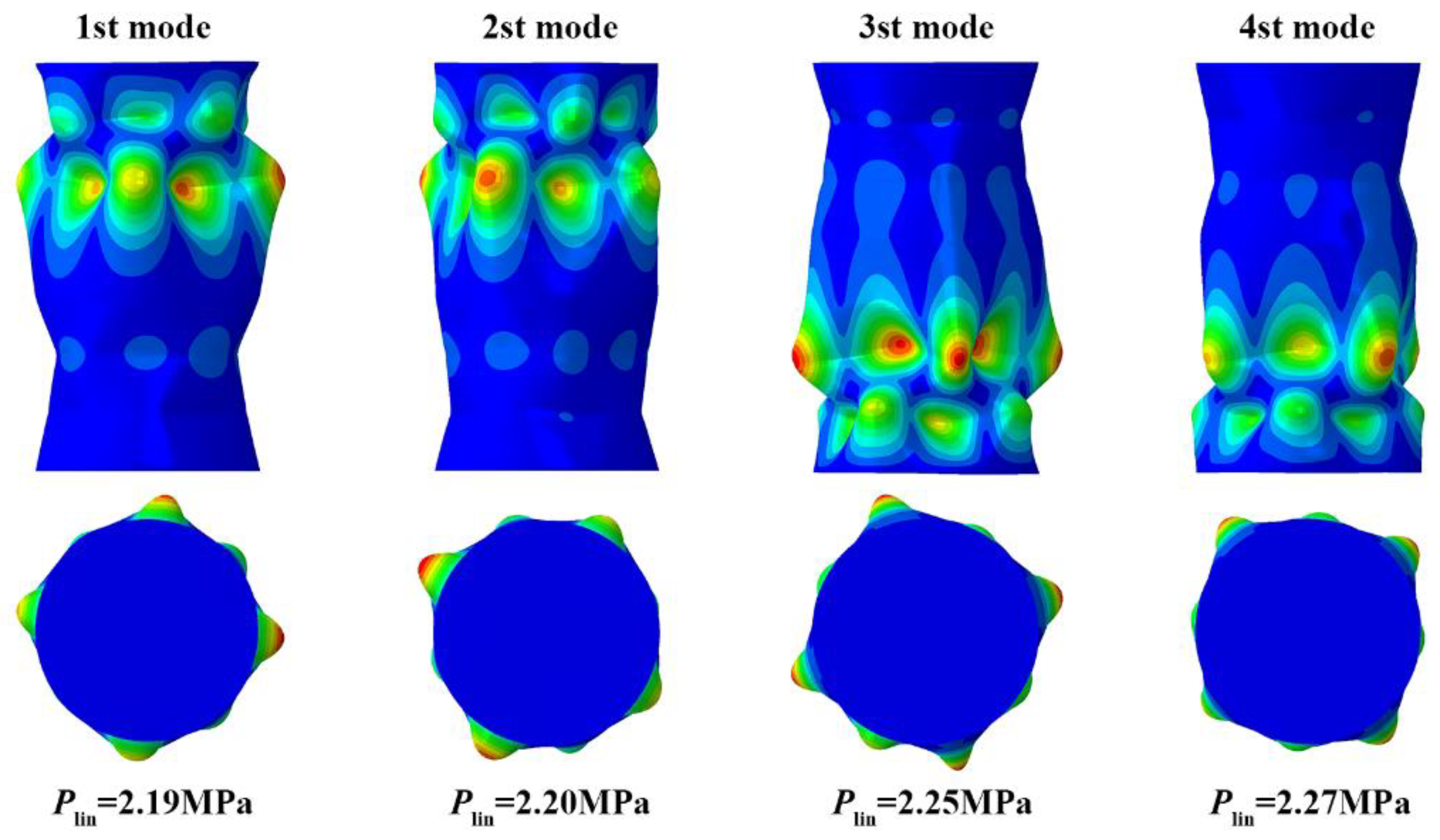
The linear models of the hulls are presented in Figure 16 and Figure 18. Figure 16 depicts the first four linear buckling modes of the cylindrical pressure hull, showing a single axial half-wave and several circumferential waves; these results were consistent with the observations illustrated in Figure 9. Because the fabricated wave-shaped pressure hull exhibited major geometric imperfections relative to the ideal wave-shaped pressure hull, the buckling mode of the fabricated wave-shaped pressure hull diverged considerably from the observations illustrated in Figure 9. Buckling was localized in either the upper or lower half of the fabricated shell, characterized by a single axial wave and several circumferential waves. Furthermore, the first four orders of the linear buckling loads for the cylindrical pressure hull were almost identical but were all significantly higher than the experimental load; this pattern was also observed for the wave-shaped pressure hull because of material and geometric nonlinearity.
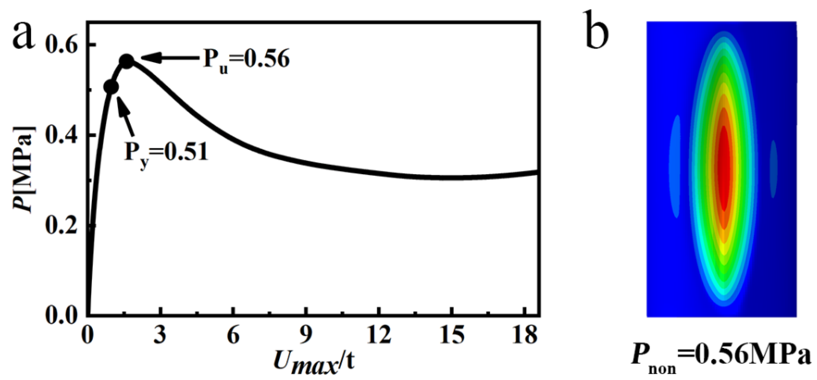
Given the obtained results, nonlinear analysis was necessary. The numerical results all indicated unstable post-buckling behavior and an elastic–plastic buckling regime (Figure 17 and Figure 19). The first yielding occurred during the pre-buckling stage at a point distant from the critical buckling point. This phenomenon was particularly prominent in the case of the wave-shaped pressure hull, where imperfections due to geometric differences led to stress concentration. The post buckling modes manifested as local dimples, and their forms were consistent with the experimental observations presented in Figure 14b and Figure 15b. For nonlinear buckling loads, the obtained simulation and experimental results exhibited strong agreement. For the wave-shaped pressure hull, the simulated and experimental buckling loads were 1.18 and 1.03 MPa, respectively; that is, the ratio of the simulated buckling load to the experimental buckling load was 1.146. The lower experimental values relative to the simulation values were primarily attributed to localized thinning caused by weld grinding and surface polishing. The cylindrical pressure hull had a simulated load of 0.56 MPa, which was close to its experimental load of 0.55 MPa. The ratio of the simulated buckling load to the experimental buckling load was 1.018, confirming the accuracy of the FEM. Furthermore, these findings are consistent with the numerical results reported in Section 3 of this paper.

4.3. Semi-Analytical Evaluation of the Fabricated Wave-Shaped Pressure Hull

Various semi-analytical formulas for evaluating the loading capacity of cylindrical pressure hulls have been proposed, such as the NASA equation [41], the Venstel–Krauthaer equation [44], and the Ross equation [45], indicated as follows:
P C y l i n d e r N A S A = 0.926 E γ R C y l i n d e r t 2.5 H R C y l i n d e r   .
P C y l i n d e r V e n = 0.92 E t H   t R C y l i n d e r 1.5   .
P C y l i n d e r R o s s = 2.6 E t 2 r 2.5 H 2 R C y l i n d e r 0.45 t 2 R C y l i n d e r 0.5 .
where E is the Young’s modulus, t is the wall thickness, RCylinder is the cylinder radius, γ is the safety factor ( γ = 0.7), and H is the cylinder length.
A wave-shaped pressure hull is a type of rotational cylindrical structure. Therefore, the nonlinear critical buckling load (Pcr) of the wave-shaped pressure hull could be obtained by multiplying the load-bearing capacity correction coefficient (η) of the wave-shaped pressure hull by the loading capacity (Pcylinder) of the equivalent cylindrical pressure hull as follows:
P c r = η P c y l i n d e r   .
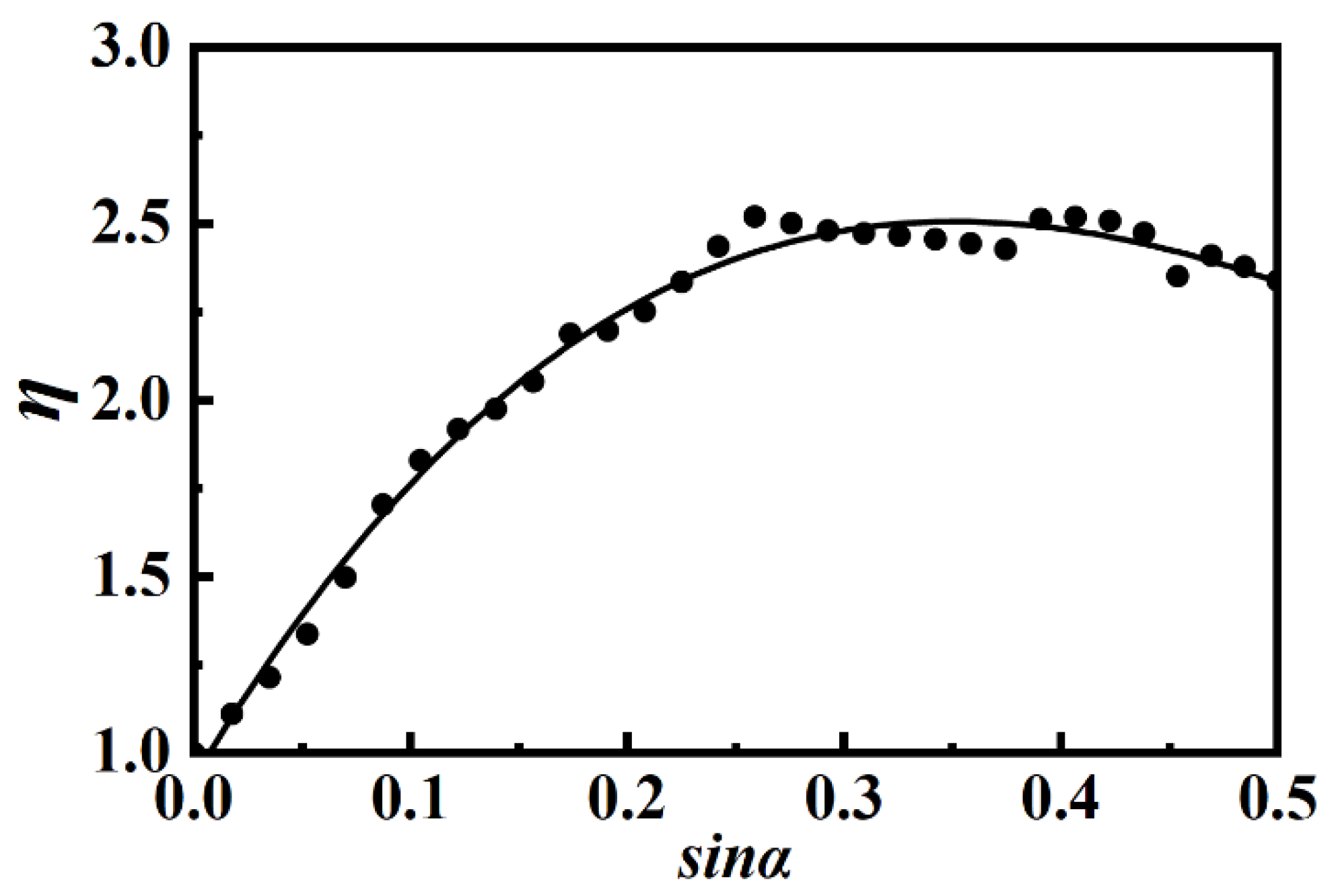
The load-bearing capacity correction coefficient (η) of the wave-shaped pressure hull is defined as the ratio of the nonlinear buckling load of this hull to that of its equivalent cylindrical pressure hull. Figure 20 illustrates the relationship between η and sinα (the sine value of the slant angle; data derived from Figure 8). The load-bearing capacity coefficient (η) was obtained by combining the linear and nonlinear regression analysis results using SPSS Statistics. The value of the coefficient of determination (R2) is 0.99.
η = 10.064 sin 3 α 19.844 sin 2 α + 10.22 sin α + 0.928   .
The radius RCylinder of the equivalent cylindrical pressure hull was determined on the basis of the principle of equal closed capacity V as follows:
R C y l i n d e r = ( 6 + 4 cos α ) ( R h sin α ) 2 + ( 3 + 4 cos α ) R 2 + 4 R ( R h sin α ) cos α 12 cos α + 9   .
Thus, the nonlinear critical buckling load (Pcr) of the wave-shaped pressure hull could be derived by applying three semi-analytical formulas for the equivalent cylindrical pressure hull.
The buckling loads of the wave-shaped pressure hulls were predicted using semi-analytical formulas (Table 3). The estimated-to-tested buckling load ratios of 0.912, 1.291, and 1.320 were obtained using the Modify-NASA, Modify-Ven, and Modify-Ross equations, respectively. The findings suggested that the Modify-NASA equation provided an accurate but slightly conservative estimation, indicating the feasibility of extending the classic formula for cylindrical pressure hulls to suit wave-shaped pressure hulls.

5. Conclusions

In this study, the buckling behavior of wave-shaped pressure hulls was investigated numerically and experimentally. The main conclusions are summarized as follows:
(1)
The slant angle of a wave-shaped pressure hull affected the hull’s linear and nonlinear buckling loads. In terms of load-bearing capacity, the 30 wave-shaped pressure hulls outperformed the equivalent cylindrical pressure hull. Furthermore, the optimal slant angle for wave-shaped pressure hulls was 14°–16°.
(2)
A wave-shaped pressure hull was less sensitive to imperfections at any amplitude compared with the equivalent cylindrical pressure hull. This finding extends the literature on segmented pressure hulls, which only exhibit lower imperfection sensitivity than equivalent cylindrical pressure hulls when large imperfections are involved.
(3)
The experimental and numerical results were consistent. The simulated and experimental buckling loads of the wave-shaped pressure hull were 1.18 and 1.03 MPa, respectively. The simulated load of the cylindrical pressure hull was 0.56 MPa, which was close to its experimental load of 0.55 MPa. The simulated-to-experimental buckling load ratio ranged from 1.018 to 1.146, confirming the accuracy of the FEM.
(4)
The experimental buckling load of the equivalent cylindrical pressure hull (0.55 MPa) was considerably lower than that of the wave-shaped pressure hull (1.03 MPa). That is, the buckling load of the wave-shaped pressure hull was approximately 1.87 times that of the equivalent cylindrical pressure hull.
(5)
A formula for estimating the load-bearing capacity of a wave-shaped pressure hull was designed in this study. This formula incorporated a correction coefficient and the classical semi-analytical formula for cylindrical pressure hulls. The formula for calculating the correction coefficient was obtained on the basis of numerical evaluation and regression analysis results. The estimated-to-tested buckling load ratios of 0.912, 1.291, and 1.320 were obtained using the Modify-NASA, Modify-Ven, and Modify-Ross equations, respectively. The corresponding findings suggest that the Modify-NASA equation provided an accurate but slightly conservative estimation.

Author Contributions

Conceptualization, L.Z. and J.Z.; methodology, L.Z. and J.Z.; software, L.Z.; validation, L.Z. and Y.H.; investigation, L.Z. and H.J.; data curation, L.Z.; writing—original draft preparation, L.Z.; writing—review and editing, Y.H. and J.Z.; visualization, Y.H. and H.J.; supervision, Y.H. and H.J.; funding acquisition, J.Z.; formal analysis, Y.H. and J.Z. All authors have read and agreed to the published version of the manuscript.

Funding

This research was supported by the Science Fund for Distinguished Young Scholars of Jiangsu Province (grant number: BK20230014).

Institutional Review Board Statement

Not applicable.

Informed Consent Statement

Not applicable.

Data Availability Statement

All data are included in the manuscript.

Conflicts of Interest

The authors declare no conflicts of interest.

References

  1. Ross, C.T.F.; Little, A.P.F. The Buckling of a Corrugated Carbon Fibre Cylinder under External Hydrostatic Pressure. Ocean Eng. 2001, 28, 1247–1264. [Google Scholar] [CrossRef]
  2. Ross, C.T.F. A Conceptual Design of an Underwater Vehicle. Ocean Eng. 2006, 33, 2087–2104. [Google Scholar] [CrossRef]
  3. Błachut, J.; Smith, P. Buckling of Multi-Segment Underwater Pressure Hull. Ocean Eng. 2008, 35, 247–260. [Google Scholar] [CrossRef]
  4. Nho, I.S.; Ryu, J.W.; Lim, S.J.; Cho, S.R.; Cho, Y.S. Buckling Analysis of Circular Cylinders with Initial Imperfection Subjected to Hydrostatic Pressure. J. Soc. Nav. Archit. Korea 2017, 54, 267–273. [Google Scholar] [CrossRef]
  5. Basaglia, C.; Camotim, D.; Silvestre, N. GBT-Based Buckling Analysis of Steel Cylindrical Shells under Combinations of Compression and External Pressure. Thin-Walled Struct. 2019, 144, 106274. [Google Scholar] [CrossRef]
  6. Li, Z.; Pasternak, H.; Geißler, K. Experiment-based Statistical Distribution of Buckling Loads of Cylindrical Shells. Ce/Papers 2023, 6, 1816–1820. [Google Scholar] [CrossRef]
  7. Li, Z.; Pasternak, H.; Geißler, K. Buckling Analysis of Cylindrical Shells Using Stochastic Finite Element Method with Random Geometric Imperfections. Ce/Papers 2022, 5, 653–658. [Google Scholar] [CrossRef]
  8. Sowiński, K. Experimental and Numerical Verification of Stress Distribution in Additive Manufactured Cylindrical Pressure Vessel—A Continuation of the Dished End Optimization Study. Thin-Walled Struct. 2023, 183, 110336. [Google Scholar] [CrossRef]
  9. Zingoni, A. Liquid-Containment Shells of Revolution: A Review of Recent Studies on Strength, Stability and Dynamics. Thin-Walled Struct. 2015, 87, 102–114. [Google Scholar] [CrossRef]
  10. Foryś, P. Optimization of Cylindrical Shells Stiffened by Rings under External Pressure Including Their Post-Buckling Behaviour. Thin-Walled Struct. 2015, 95, 231–243. [Google Scholar] [CrossRef]
  11. Shiomitsu, D.; Yanagihara, D. Elastic Local Shell and Stiffener-Tripping Buckling Strength of Ring-Stiffened Cylindrical Shells under External Pressure. Thin-Walled Struct. 2020, 148, 106622. [Google Scholar] [CrossRef]
  12. Ghanbari Ghazijahani, T.; Jiao, H.; Holloway, D. An Experimental Study on Externally Pressurized Stiffened and Thickened Cylindrical Shells. Thin-Walled Struct. 2014, 85, 359–366. [Google Scholar] [CrossRef]
  13. Do, Q.T.; Muttaqie, T.; Park, S.-H.; Shin, H.K.; Cho, S.-R. Ultimate Strength of Intact and Dented Steel Stringer-Stiffened Cylinders under Hydrostatic Pressure. Thin-Walled Struct. 2018, 132, 442–460. [Google Scholar]
  14. Ross, C.T.F.; Waterman, G.A. Inelastic Instability of Circular Corrugated Cylinders under External Hydrostatic Pressure. Ocean Eng. 2000, 27, 331–343. [Google Scholar] [CrossRef]
  15. Ross, C.T.F. Collapse of Corrugated Circular Cylinders under Uniform External Pressure. Int. J. Struct. Stab. Dyn. 2005, 5, 241–257. [Google Scholar] [CrossRef]
  16. Ross, C.T.F.; Terry, A.; Little, A.P.F. A Design Chart for the Plastic Collapse of Corrugated Cylinders under External Pressure. Ocean Eng. 2001, 28, 263–277. [Google Scholar] [CrossRef]
  17. Zhang, J.; Zhang, S.; Cui, W.; Zhao, X.; Tang, W.; Wang, F. Buckling of Circumferentially Corrugated Cylindrical Shells under Uniform External Pressure. Ships Offshore Struct. 2019, 14, 879–889. [Google Scholar] [CrossRef]
  18. Chrysanidis, T. The Effect of Longitudinal Reinforcement Ratio on the Lateral Buckling Behavior of R/C Walls Modelled Using Prism Elements. J. Build. Eng. 2021, 42, 102456. [Google Scholar] [CrossRef]
  19. Cho, S.-R.; Muttaqie, T.; Do, Q.T.; Kim, S.; Kim, S.M.; Han, D.-H. Experimental Investigations on the Failure Modes of Ring-Stiffened Cylinders under External Hydrostatic Pressure. Int. J. Nav. Archit. Ocean Eng. 2018, 10, 711–729. [Google Scholar] [CrossRef]
  20. Cho, S.R.; Muttaqie, T.; Do, Q.T.; Park, S.H.; Kim, S.M.; So, H.Y.; Sohn, J.M. Experimental Study on Ultimate Strength of Steel-Welded Ring-Stiffened Conical Shell under External Hydrostatic Pressure. Mar. Struct. 2019, 67, 102634. [Google Scholar] [CrossRef]
  21. Ghanbari Ghazijahani, T.; Jiao, H.; Holloway, D. Longitudinally Stiffened Corrugated Cylindrical Shells under Uniform External Pressure. J. Constr. Steel Res. 2015, 110, 191–199. [Google Scholar] [CrossRef]
  22. Ghanbari Ghazijahani, T.; Sadighi Dizaji, H.; Nozohor, J.; Zirakian, T. Experiments on Corrugated Thin Cylindrical Shells under Uniform External Pressure. Ocean Eng. 2015, 106, 68–76. [Google Scholar] [CrossRef]
  23. Ross, C.T.F. Pressure Vessels: External Pressure Technology, 2nd ed.; Woodhead Publishing: Sawston, UK, 2011; ISBN 9780857092489. [Google Scholar]
  24. Zhang, J.; Zheng, L.; Kaewunruen, S.; Zhan, M.; Liu, P. Nonlinear Buckling of Steel Cone-Segmented Cylinders under External Pressure: Numerical and Experimental Evaluations. Ships Offshore Struct. 2024, 1–12. [Google Scholar] [CrossRef]
  25. Documentation, A. Abaqus Analysis User’s Guide; Simulia: Johnston, RI, USA, 2014. [Google Scholar]
  26. Ismail, M.S.; Ifayefunmi, O.; Fadzullah, S.H.S.M.; Johar, M. Buckling of Imperfect Cone-Cylinder Transition Subjected to External Pressure. Int. J. Press. Vessel. Pip. 2020, 187, 104173. [Google Scholar] [CrossRef]
  27. Rules for Classification of Diving Systems and Submersibles; China Classification Society: Beijing, China, 2018.
  28. Zhang, J.; Tan, J.; Tang, W.; Wang, F.; Zhao, X. International Journal of Pressure Vessels and Piping Collapse Performance of Externally Pressurized Resin Egg-Shaped Shells with Corrosion Thinning. Int. J. Press. Vessel. Pip. 2019, 177, 103993. [Google Scholar] [CrossRef]
  29. Zhang, J.; Tan, J.; Tang, W.; Zhao, X.; Zhu, Y. Experimental and Numerical Collapse Properties of Externally Pressurized Egg-Shaped Shells under Local Geometrical Imperfections. Int. J. Press. Vessel. Pip. 2019, 175, 103893. [Google Scholar] [CrossRef]
  30. Zhang, J.; Hua, Z.; Wang, F.; Tang, W. Buckling of an Egg-Shaped Shell with Varying Wall Thickness under Uniform External Pressure. Ships Offshore Struct. 2018, 14, 559–569. [Google Scholar] [CrossRef]
  31. Zhang, J.; Wang, W.M.; Cui, W.C.; Tang, W.X.; Wang, F.; Chen, Y. Buckling of Longan-Shaped Shells under External Pressure. Mar. Struct. 2018, 60, 218–225. [Google Scholar] [CrossRef]
  32. Wang, Y.; Gu, Y.; Liu, J. A Domain-Decomposition Generalized Finite Difference Method for Stress Analysis in Three-Dimensional Composite Materials. Appl. Math. Lett. 2020, 104, 106226. [Google Scholar] [CrossRef]
  33. Kabir, H.; Aghdam, M.M. A Robust Bézier Based Solution for Nonlinear Vibration and Post-Buckling of Random Checkerboard Graphene Nano-Platelets Reinforced Composite Beams. Compos. Struct. 2019, 212, 184–198. [Google Scholar] [CrossRef]
  34. Bert, C.W.; Malik, M. Differential Quadrature: A Powerful New Technique for Analysis of Composite Structures. Compos. Struct. 1997, 39, 179–189. [Google Scholar] [CrossRef]
  35. Błachut, J. Buckling of Externally Pressurised Barrelled Shells: A Comparison of Experiment and Theory. Int. J. Press. Vessel. Pip. 2002, 79, 507–517. [Google Scholar] [CrossRef]
  36. Bałchut, J.; Wang, P. Buckling of Barreled Shells Subjected to External Hydrostatic Pressure. J. Press. Vessel Technol. Trans. ASME 2001, 123, 232–239. [Google Scholar] [CrossRef]
  37. Błachut, J.; Smith, P. Tabu Search Optimization of Externally Pressurized Barrels and Domes. Eng. Optim. 2007, 39, 899–918. [Google Scholar] [CrossRef]
  38. Błachut, J. Optimal Barreling of Steel Shells via Simulated Annealing Algorithm. Comput. Struct. 2003, 81, 1941–1956. [Google Scholar] [CrossRef]
  39. Wagner, H.N.R.; Hühne, C.; Zhang, J.; Tang, W. On the Imperfection Sensitivity and Design of Spherical Domes under External Pressure. Int. J. Press. Vessel. Pip. 2020, 179, 104015. [Google Scholar] [CrossRef]
  40. Wagner, H.N.R.; Hühne, C.; Niemann, S. Robust Knockdown Factors for the Design of Spherical Shells under External Pressure: Development and Validation. Int. J. Mech. Sci. 2018, 141, 58–77. [Google Scholar] [CrossRef]
  41. National Aeronautics and Space Administration (NASA). Buckling of Thin-Walled Circular Cylinders; NASA: Washington, DC, USA, 1965.
  42. Hilburger, M.W. Developing the next Generation Shell Buckling Design Factors and Technologies. In Proceedings of the 53rd AIAA/ASME/ASCE/AHS/ASC Struct, Structural Dynamics and Materials Conference, Honolulu, HI, USA, 23–26 April 2012; pp. 1–15. [Google Scholar] [CrossRef]
  43. Hilburger, M.W.; Nemeth, M.P.; Starnes, J.H. Shell Buckling Design Criteria Based on Manufacturing Imperfection Signatures. In Proceedings of the 44th AIAA/ASME/ASCE/AHS/ASC Struct, Structural Dynamics and Materials Conference, Norfolk, VA, USA, 7–10 April 2003; Volume 44. [Google Scholar]
  44. Cartwright, R. Book Reviews: Book Reviews. Perspect. Public Health 2010, 130, 239. [Google Scholar] [CrossRef]
  45. Ross, C.T.F. A Proposed Design Chart to Predict the Inelastic Buckling Pressures for Conical Shells under Uniform External Pressure. Mar. Technol. SNAME News 2007, 44, 77–81. [Google Scholar] [CrossRef]
Figure 1. (a) Cylindrical pressure hull stiffened by rings, (b) cylindrical pressure hull stiffened by stringers, and (c) corrugated cylindrical pressure hull.
Jmse 12 00821 g001
Figure 2. Notations for wave-shaped pressure hulls.
Jmse 12 00821 g002
Figure 3. Parameters of simulated pressure hulls.
Jmse 12 00821 g003
Figure 4. Finite element models of wave-shaped pressure hulls.
Jmse 12 00821 g004
Figure 5. Finite element models of wave-shaped pressure hulls (α = 15°).
Jmse 12 00821 g005
Figure 6. Preform fabrication involving (a) blanking, (b) bending, (c) assembly, (d) welding, and (e) grinding.
Jmse 12 00821 g006
Figure 7. Photographs of experimental setups for the fabricated preform: (a) geometric measurement, (b) thickness measurement, and (c) hydrostatic test.
Jmse 12 00821 g007
Figure 8. Nonlinear and linear buckling loads of a wave-shaped pressure hull normalized by loads of an equivalent cylindrical pressure hull.
Jmse 12 00821 g008
Figure 9. Linear buckling modes of an equivalent cylindrical pressure hull and a wave-shaped pressure hull.
Jmse 12 00821 g009
Figure 10. (a) Knockdown factors of three pressure hulls, (b) normalized nonlinear buckling loads of two pressure hulls with an optimized slant angle at multiple imperfection amplitudes, and (c) profile diagrams of three pressure hulls.
Jmse 12 00821 g010
Figure 11. Representative equilibrium paths of (a) an imperfect equivalent cylindrical pressure hull and (b) an imperfect wave-shaped pressure hull with a 15° angle.
Jmse 12 00821 g011
Figure 12. Deformation evolution of (a) an imperfect equivalent cylindrical pressure hull and (b) an imperfect wave-shaped pressure hull with a 15° angle.
Jmse 12 00821 g012
Figure 13. Differences between the fabricated and nominal geometries of two fabricated pressure hulls.
Jmse 12 00821 g013
Figure 14. (a) Applied pressure values recorded during hydrostatic testing of the cylindrical pressure hull and (b) photograph of the fabricated cylindrical pressure hull after hydrostatic testing.
Jmse 12 00821 g014
Figure 15. (a) Applied pressure values recorded during hydrostatic testing of the wave-shaped pressure hull and (b) photograph of the fabricated pressure hull after hydrostatic testing.
Jmse 12 00821 g015
Figure 16. Eigenvalues and eigenmodes obtained through linear buckling analysis of pressure hulls.
Jmse 12 00821 g016
Figure 17. (a) Equilibrium paths of the cylindrical pressure hull and (b) post-buckling modes of the cylindrical pressure hull.
Jmse 12 00821 g017
Figure 18. Eigenvalues and eigenmodes obtained through linear buckling analysis of the wave-shaped pressure hull.
Jmse 12 00821 g018
Figure 19. (a) Equilibrium paths of the cylindrical pressure hull and (b) post-buckling modes of the wave-shaped pressure hull.
Jmse 12 00821 g019
Figure 20. Fitting formula for obtaining the enhanced loading capacity of a wave-shaped pressure hull.
Jmse 12 00821 g020
Table 1. Constant parameters of simulated pressure hulls.
H [mm]T [mm]T [mm]V [mm3]
395301.07412,427,945
Table 2. Geometric parameters of two fabricated pressure hulls.
SampleTmin
[mm]
Tmax
[mm]
Tave
[mm]
St.dev.
[mm]
S
[mm2]
V
[mm3]
Cylindrical
pressure hull
1.0721.0901.0830.003349,100(1.000)14,438,837(1.009)
Wave-shaped pressure hull1.0081.0981.0750.016363,845(0.990)14,581,047(0.996)
Table 3. Loading strengths of fabricated cylinders obtained through semi-analytical formulas and experimental testing.
Pcr [MPa]Pexp [MPa]Pcr/Pexp
Modify-NASA0.941.030.912
Modify-Ven1.331.031.291
Modify-Ross1.361.031.320
Disclaimer/Publisher’s Note: The statements, opinions and data contained in all publications are solely those of the individual author(s) and contributor(s) and not of MDPI and/or the editor(s). MDPI and/or the editor(s) disclaim responsibility for any injury to people or property resulting from any ideas, methods, instructions or products referred to in the content.