Article

Numerical Investigation of Solitary Wave Attenuation by a Vertical Plate-Type Flexible Breakwater Constructed Using Hyperelastic Neo-Hookean Material

Department of Civil and Environmental Engineering, Nagoya University, Nagoya 464-8603, Japan
*
Author to whom correspondence should be addressed.
J. Mar. Sci. Eng. 2024, 12(6), 1004; https://doi.org/10.3390/jmse12061004
Submission received: 24 April 2024 / Revised: 9 June 2024 / Accepted: 13 June 2024 / Published: 16 June 2024
(This article belongs to the Special Issue Novel Materials Theories and Applications in Ocean Engineering)

Abstract

:
This study conducted numerical investigations on solitary wave attenuation by a vertical plate-type flexible breakwater constructed using hyperelastic neo-Hookean material. The wave attenuation performance and elastic behaviors of the flexible breakwater were discussed systematically by considering the effects of three prominent factors: mass coefficient, stiffness coefficient, and Poisson’s ratio. It is indicated that more compressible and flexible materials are beneficial for enhancing efficiency in mitigating solitary wave energy and protecting the structure from damage. In addition, the performance of the hyperelastic neo-Hookean material model was compared with that of a linear elastic isotropic material model coupled with linear and nonlinear geometry analysis (LGEOM and NLGEOM) by evaluating several key targets: wave reflection coefficient, transmission coefficient, horizontal tip displacement, and wave load. Our findings revealed that the hyperelastic neo-Hookean material model showed almost the same predictions as the linear elastic isotropic material model with NLGEOM, but significantly diverged from that with LGEOM. The linear elastic isotropic material model with LGEOM cannot capture the nonlinear variations in structural geometry and stress–strain relationship, resulting in the underestimation and overestimation of horizontal tip displacement under moderate and extreme wave loads, respectively. Moreover, it underestimates the damage inflicted by solitary waves due to inaccurately predicted wave reflection and transmission.

1. Introduction

In recent years, flexible breakwaters have attracted widespread attention, due to the lower construction expenses, great adaptability to the seabed terrain, and environmental friendliness. Constructing the coastal flexible protection system is becoming a prominent strategy to resist potential wave damage and protect coastal infrastructures all over the world.
Over the past years, many researchers have focused on flexible breakwaters and conducted a great deal research to understand the wave dissipation mechanisms, structural design, and optimization of flexible breakwaters. A small number of researchers have conducted laboratory experiments to explore interactions between flexible structures and ocean waves. Tanaka et al. [1] and Guo et al. [2] carried out physical experiments to study wave reflection, transmission, and attenuation by a fluid-filled membrane breakwater and a vertical flexible porous multi-membrane-type breakwater. They discussed the effects of material properties on the efficiency of both types of breakwaters. Loukogeorgaki et al. [3,4] carried out 3D experimental investigations on the hydroelastic and structural responses of pontoon-type modular floating breakwaters under various wave conditions. The studies emphasized the significant impact of wave period, obliquity, and height on the internal forces of connectors and mooring line tensions, highlighting the necessity of integrating hydroelastic response assessments into the design phase for optimal performance. They underline the importance of considering hydroelasticity in structural evaluation to ensure the effectiveness and stability of floating breakwaters. Sree et al. [5] and Hsiao et al. [6] concentrated on the flexible plate structure. The former revealed the propagation and evolution process of periodic waves when interacting with a submerged viscoelastic plate. The latter investigated solitary wave attenuation by the vertical thin plate constructed by three different materials: Bakelite, rubber, and silicone. Furthermore, a theoretical analysis method was also extensive to address the complex hydroelasticity phenomenon. Abul-Azm [7] developed an analytical, computationally efficient method for the wave reflection and dynamic displacement of a submerged flexible breakwater using an eigenfunction expansion technique. Peter and Meylan [8] present a time-domain solution for the interaction between linear water waves and a vertical elastic plate using a generalized eigenfunction expansion method. The research primarily focused on single-frequency solutions, and the time-dependent problem was solved by expanding these solutions, demonstrating the method’s numerical accuracy through experiments. Lan et al. [9] presented the Bragg scattering of water waves propagating over a series of rectangular poro-elastic submerged breakwaters through mathematical investigation. Li et al. [10] developed analytical solutions for Bragg scattering of water waves by multiple submerged perforated semi-circular breakwaters based on potential theory, employing multipole expansions and separation of variables to express the velocity potentials. The study validated these analytical solutions through experimental tests and comparisons with multi-domain BEM solutions, demonstrating their effectiveness in predicting reflection, transmission, and energy loss coefficients under various wave conditions.
Numerical simulations have become the preferred method for studying wave interactions with flexible structures, surpassing traditional experimental and analytical approaches. The complexity of hydroelastic problems that combine fluid dynamics and structural mechanics makes it challenging to obtain accurate solutions using just one numerical method. Consequently, a great deal of research makes contributions to the advancement of fluid–structure interaction (FSI) algorithms within numerical modeling frameworks. Notably, Das and Cheung [11] described a 3D coupled boundary element and finite element model for analyzing the dynamic response of fluid-filled membranes in gravity waves. The model incorporates small amplitude assumptions for surface waves and membrane deflection, linearizing the problem for efficient frequency domain solutions, and validates the approach through comparisons with 2D numerical models and 3D laboratory data, highlighting resonance characteristics and discrepancies. Furthermore, Liao and Hu [12] integrated the finite difference method (FDM) with the finite element method (FEM) to simulate how a thin elastic plate interacts with a flow over a free surface. To enhance the accuracy of their simulations, they employed the virtual structure approach alongside the constraint interpolation profile method. They thoroughly examined the impact of various factors on the model’s performance, including the number of elements in the structure, the resolution of the background grid, and the thickness of the virtual structure. In a related vein, Zhao et al. [13] proposed a coupled model, which combined the constraint interpolation profile (CIP) viscous flow model with FEM. They also used a modified ghost cell immersed boundary method in this study to increase the accuracy of FSI simulation. This analysis focused on understanding the membrane breakwater’s structural response through detailed assessments of displacement and velocity distributions of the midpoint.
Moreover, the combination of the finite volume method (FVM) with FEM was also a strategy to overcome these hydroelastic challenges. Tukovic et al. [14] and Cardiff et al. [15] established the fully coupled FSI framework solids4foam through integrating structural solver modules into the OpenFOAM environment as a library file. To accomplish the high-resolution simulations of wave interactions with elastic structures, some researchers extend the capabilities of solids4foam by adopting waves2Foam and IHFOAM as tools for wave generation and damping [16]. They developed this multiphase fluid–structure interaction (FSI) code to simulate the hydroelastic response of sea ice using IHFOAM and solids4foam, achieving full coupling between wave field solutions and ice deformation. The model shows good agreement with experiments, accurately predicting wave transmission and reflection over a floating ice sheet, and it highlights the benefits of two-way coupling for realistic over-wash modeling. Huang et al. [17] employed this coupled model to simulate the hydroelastic interaction between nonlinear ocean waves and a deformable submerged horizontal plate breakwater (SHPB), demonstrating that the deformation of the SHPB significantly improves wave damping performance compared to a rigid structure. The study found that optimal SHPB performance occurs when the vibration amplitude matches the incident wave amplitude, and it offers a computational methodology for hydroelastic SHPB design. Hu et al. [18] used this fully coupled model to systematically investigate the hydroelastic behavior of an elastic wall in periodic waves, finding that increased flexibility significantly reduces wave reflection and loading on the wall. The study concludes that material damping has a negligible influence on hydroelastic interactions under continuous low-frequency wave loading but may be important for other environmental loads like seismic events.
Additionally, Bungartz et al. [19] developed preCICE, an open-source parallel coupling library designed for multiphysics surface coupling, enabling the integration of OpenFOAM with CalculiX [20]. This integration built the connection of pimpleFoam and interFoam with the FEM structural code CalculiX [21], enhancing the capability to simulate complex interactions between different physical processes. Based on preCICE, we set up the connections between wave2foam and Calculix to realize the wave interaction with elastic structures in our previous work [22]. A linear elastic isotropic material model with LGEOM was employed to describe the dynamic response of the vertical plate-type flexible breakwater. However, there is a significant drawback to this elastic model, which is just applied to small strain of structures. When dealing with the problem of large structural strain, this elastic model cannot reproduce the nonlinear behaviors of material and structure geometry, resulting in inaccurate prediction of structure displacement.
This study furthers our previous works [22] to consider the large strain of structure. The nonlinear elastic behaviors of the vertical plate-type flexible breakwater are described by employing two nonlinear elastic models, the linear elastic isotropic material model with NLGEOM and the hyperelastic neo-Hookean material model. The solitary wave reflection, transmission, attenuation mechanisms, and structural deformation simulated using the hyperelastic neo-Hookean material model were studied systematically by considering several prominent material properties: Poisson’s Ratio, mass, and stiffness coefficients. Three elastic material models were compared to present the different performance on reducing wave energy and structural load through four evaluation indicators: wave reflection coefficient, transmission coefficient, the maximum horizontal tip displacement, and wave load. This paper is outlined as follows: Section 2 presents the governing equations, numerical methods, coupling framework, and information about model validation. Section 3 discusses the efficiency of a vertical plate-type flexible breakwater in dissipating wave energy and its elastic behaviors characterized by three different elastic material models when subjected to a solitary wave. Conclusions are summarized in Section 4.

2. Numerical Methods

This research used a partitioned FSI-coupled framework to simulate the complex hydroelastic process during interactions between waves and an elastic structure. The computational domain was divided into two parts, a fluid part and a solid part. The fluid part was handled by the wave solver waves2Foam, and the solid part was solved by an FEM structural solver. They were coupled through the interface coupling provided by preCICE. All data exchange processes were performed on the shared interface between the fluid and the solid domain.

2.1. Fluid Solver

In this coupled framework, a wave solver waves2Foam [23] was employed to provide a variety of algorithms for wave generation and damping. It is integrated in a computational fluid dynamic solver OpenFOAM, which is widely applied for simulating two-phase incompressible flow using the finite volume method. The continuity and incompressible Navier–Stokes equations were employed to describe mass and momentum conservation as follows:
· U = 0
ρ U t + · ρ U U = p + · ( μ t U + U T + ρ g
where U is the fluid velocity vector, ρ is the fluid density, p is the pressure, g is the gravitational acceleration, μ t is the dynamic viscosity, and t is the time. The free surface was simulated by the volume of fluid (VOF) method [24] as follows:
α t + · U α + · U c α 1 α = 0
where U c is the interface compressive velocity between air and water; U c = min [ c α U , m a x ( U ) ] [25]; c α represents the interface compression factor; and α denotes the phase fraction for distinguishing the form of fluid ( α = 0 for air; α = 1 for water). The phase fraction is used to describe the fluid density and viscosity:
ρ = α ρ w + 1 α ρ a
μ t = α μ w + 1 α μ a
where ρ w = 1000   k g / m 3 is the water density, ρ a = 1   k g / m 3 is the air density, μ w = 1 × 10 3   N · s / m 2 is the dynamic viscosity of water, and μ a = 1.48 × 10 5   N · s / m 2 is the dynamic viscosity of air.
The relaxation zone method was applied for wave generation and damping. As plotted in Figure 1, the numerical wave tank was divided into three distinct zones: relaxation zone, working zone, and damping zone. Jacobsen et al. [26] introduced a relaxation function that effectively controls the velocity and free surface elevation by applying wave theory specifically within the relaxation zone. It is described as follows:
U r e l a x e d = Γ x R U a n a l y t i c a l + 1 Γ x R U c o m p u t a t i o n a l
α r e l a x e d = Γ x R α a n a l y t i c a l + 1 Γ x R α c o m p u t a t i o n a l
Γ x R = 1 exp x R 3.5 1 exp 3.5 1
x R = x x s r x e r x s r
where Γ ( x R ) represents the relaxation function, x represents the position along the wave propagation direction, and x s r and x e r are the start and end coordinate of the relaxation zone along the propagation direction, respectively. The relaxation zone generates stable waves at first. And then waves propagate and interact with the structure in the working zone. At the end of the computational domain, a damping zone is used to absorb waves reflection from the outlet of the numerical wave tank. The values for both fluid velocity and free surface elevation are smoothly reduced to zero here, as detailed by Jacobsen et al. [26].

2.2. Structural Solver

The FEM structural solver CalculiX was employed to predict the elastic behaviors of the structure. The weak form of momentum conservation equation under linear and nonlinear geometry analysis is described in Equations (10) and (11), respectively.
0 = · σ + ρ s f s  
ρ s D 2 U s D t 2 = · σ + ρ s f s  
where ρ s represents the solid density, U s represents the displacement vector, σ represents the Cauchy stress tensor, and f s represents the body force per unit mass.
In order to close the Equations (10) and (11), the relationships between the stress and strain are described by the following constitutive equation:
σ = 2 μ ε + λ t r ( ε ) δ ε = ( F T + F ) / 2     L i n e a r   E l a s t i c   I s o t r o p i c   M a t e r i a l   w i t h   L G E O M
σ = J 1 F S F T   S = 2 μ E + λ t r ( E ) δ E = ( F T F δ ) / 2     L i n e a r   E l a s t i c   I s o t r o p i c   M a t e r i a l   w i t h   N L G E O M
σ = J 1 F S F T   S = W E   E = ( F T F δ ) / 2     H y p e r e l a s t i c   N e o H o o k e a n   M a t e r i a l
where ε is the infinitesimal strain tensor, t r ( ε ) is the trace of the infinitesimal strain tensor, μ and λ are Lam e ´ parameters, S is the second Piola–Kirchhoff stress tensor, W is the strain energy density, E represents the Green–Lagrange strain tensor, F is the deformation gradient, J is the determinant of the deformation gradient tensor, and δ is the unit tensor. Equations (12) and (13) are used to describe the strain–stress relationship for the linear elastic isotropic material with linear and nonlinear geometry analysis, respectively.
For the hyperelastic neo-Hookean material, the relationship of stress–strain was derived from the strain energy density function W in Equation (15). The whole derivation process is presented in Equation (14). This nonlinear elastic material takes the geometry and material nonlinearity by using Equations (11) and (14).
W = C 10 I ¯ 1 3 + 1 D 1 J 1 2
I ¯ 1 = J 2 / 3 I 1 ,   J 2 = I 3
where I 1 and I 3 are the strain invariants of the Cauchy–Green deformation tensor C , and C 10 and D 1 are the material constants, which can be calculated by shell modulus G and bulk modulus K using the following equations:
C 10 = G / 2
D 1 = 2 / K
The shell modulus G and bulk modulus K can be obtained by Young’s Modulus E and Poisson ratio v as following:
G = E 2 1 + v
K = E 3 ( 1 2 v )  
The governing equation was discretized into a linear algebraic equation system based on the finite element method as follows:
K U s + M D 2 D t 2 U s = F ,  
where K represents the global stiffness matrix, M denotes the global mass matrix, and F signifies the global force vector, respectively. The α method was applied for the time discretization of governing equation [20].

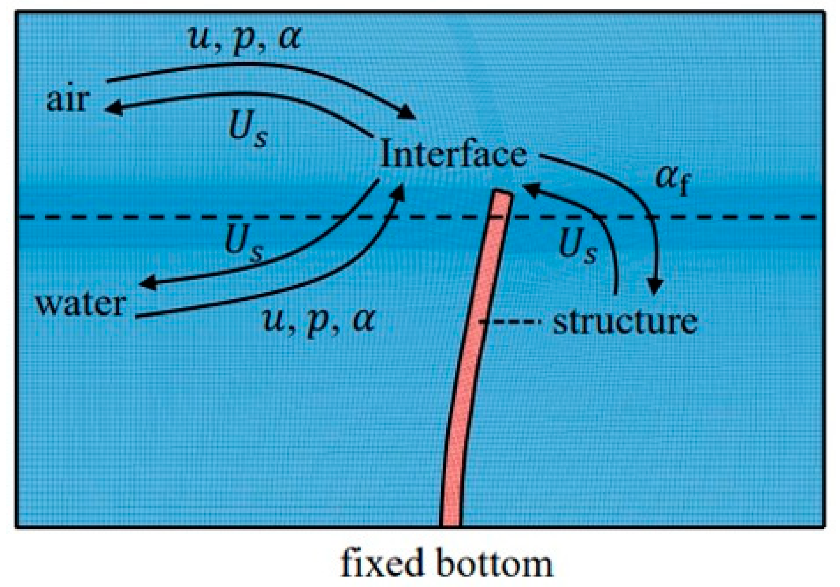
2.3. Coupling Algorithm

A partitioned interface coupling strategy was implemented to set up connections between the fluid and structural domains, allowing independent operation of the involved solvers. The related algorithms were provided by preCICE, described in Bungartz et al. [19] and Uekemann et al. [27]. This method ensures effective communication through an interface that manages data exchange between subdomains, as illustrated in Figure 2. To maintain numerical stability in addressing the complex fluid–structure interaction (FSI) challenge, a sub-iteration was included in each time step for solving the implicit scheme. An advanced interface quasi-Newton method with an inverse Jacobian from the least-squares technique was applied to strengthen the coupling stability and hasten convergence of solution [28]. The Newton–Raphson method was employed to iteratively refine the predictions of variables to solve the residual equations of displacement and fluid force at the interface. The precise data mapping on the shared interface between two solvers was achieved using a radial basis function-based interpolation described by Lindner et al. [29]. The simulations were conducted in parallel to enhance computational efficiency. The framework of this coupled algorithm is presented in Figure 3. In the illustrations, u represents the fluid velocity, p signifies pressure, and U f and U s denote the structural displacement for the fluid and solid domains, respectively. Additionally, α f and α s refer to the fluid force and structural stress, respectively.
In continuation of our previous work, this coupling model has been validated that it can predict this fluid–structure interaction phenomenon accurately. For information about the section discussing model validation, please refer to previous research [22].

3. Results

This study systematically explored the effectiveness of a vertical plate-type flexible breakwater on reducing solitary wave energy and its elastic behaviors, as modeled using hyperelastic neo-Hookean material, by examining the impacts of three significant parameters: mass coefficient, stiffness coefficient, and Poisson’s ratio, across varying wave scenarios. The performance of the hyperelastic neo-Hookean material model was evaluated in comparison to the linear elastic isotropic material model incorporating both linear and nonlinear geometry analysis. Figure 4 illustrates the computational setup for a solitary wave interacting with a vertical plate-type flexible breakwater composed of three types of elastic materials. The computational domain extended 30 m in length and 0.5 m in height, with a water depth h of 0.3 m; the breakwater’s thickness b and height l were maintained at 0.02 m and 0.33 m, respectively, positioned centrally within the numerical wave tank. The breakwater’s upper boundary was free, whereas its lower boundary was securely anchored. Across the numerical wave tank’s x-axis, 7 wave gauges (WG1 to WG7) were placed to capture the water surface elevation at positions x = −3, −2, −1, 0, 1, 2, and 3 m. This research replicated 65 cases that were previously documented by Sun et al. [22], detailed in Table 1.

3.1. Effects of Mass Coefficient

This section studied how mass coefficient influenced the efficiency of the flexible breakwater constructed by hyperelastic neo-Hookean material for solitary wave attenuation and structural deformation. The water depth (h), stiffness coefficient ( β ), and the Poisson’s ratio ( v ) were set as constant parameters, which were 0.3 m, 0.1, and 0.3, respectively. The mass coefficient ( γ ) was regarded as the variable and five values were selected as follows: 0.04, 0.06, 0.08, 0.1, and 0.12. The effects of these mass coefficients on reflection and transmission coefficients ( C r and C t , respectively), alongside the wave energy attenuation ratio E r / E i = 1 ( C r 2 + C t 2 ) , are depicted in Figure 5 for various wave scenarios. E r is the reduced wave energy and E i is the incident wave energy. The analysis revealed that the effects of the mass coefficient were insignificant on the reflection, transmission, and attenuation of solitary waves. Notably, as the wave height increased, the transmission coefficient rose, the reflection coefficient reduced, and wave energy attenuation enhanced. Figure 6 demonstrates that the mass coefficient also had almost no influence on the maximum horizontal displacement D x , m a x (normalized by wave height H ) and wave load F x , m a x (normalized by ρ g h H ) of the flexible breakwater.

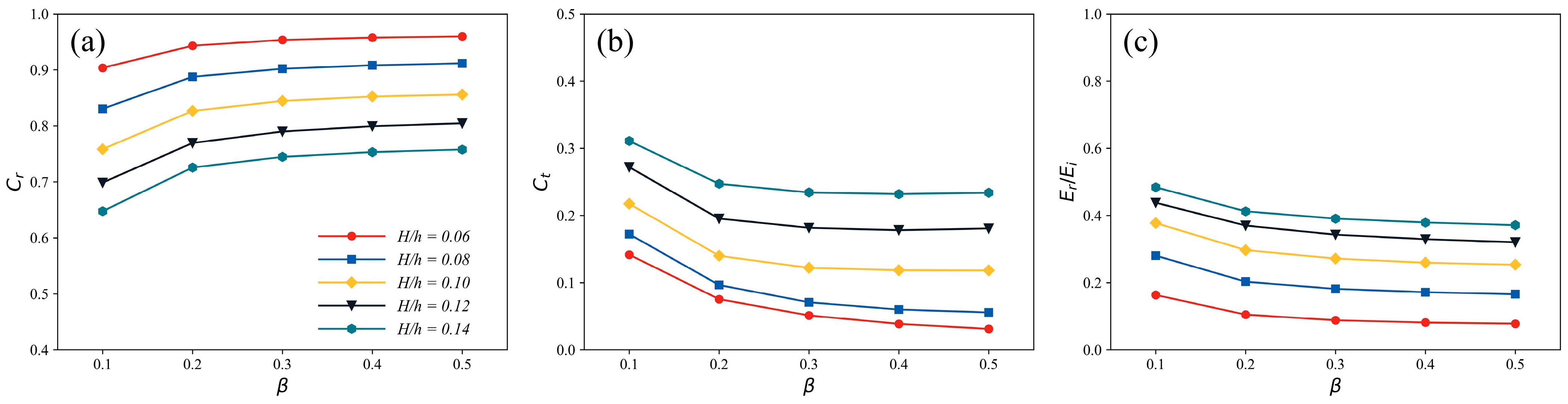
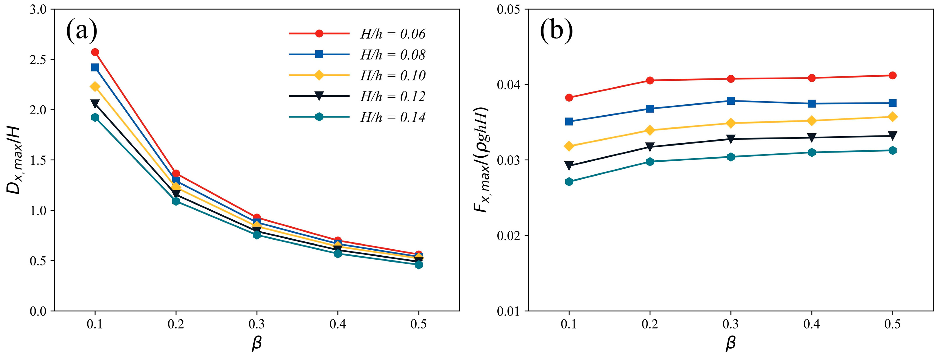
3.2. Effects of Stiffness Coefficient

This part explored the impact of varying stiffness coefficients, β = 0.1 , 0.2 , 0.3 , 0.4 , and 0.5 , on the performance of the flexible breakwater constructed by hyperelastic neo-Hookean material regarding wave dissipation and structural elastic deformation. The stiffness coefficient represented the flexibility of the breakwater. The structure can be regarded as a rigid body when the stiffness is large enough. The water depth (h), mass coefficient ( γ ), and the Poisson’s ratio ( v ) were fixed parameters, which were 0.3 m, 0.08, and 0.3, respectively. Figure 7 illustrates how stiffness coefficients affect the reflection, transmission coefficient, and the wave energy attenuation ratio. With higher stiffness coefficients, there was an increase in the wave reflection and a reduction in the wave transmission. The wave energy attenuation ratio also went down with stiffness, although the rate of decrease slowed at higher stiffness levels. The wave reflection and transmission also reached the threshold when the stiffness coefficient was large enough, indicating that a rigid breakwater can reflect more solitary wave energy and achieve less wave transmission. But, a highly flexible breakwater is more beneficial for mitigating wave energy through dynamic interactions with solitary waves, as shown in Figure 7c. Figure 8 depicts how the maximum horizontal displacement D x , m a x (normalized by the wave height H ) and the peak horizontal wave load F x , m a x (normalized by ρ g h H ), vary across different stiffness coefficients. A more flexible breakwater design led to an increase in normalized D x , m a x , while increased stiffness resulted in higher normalized F x , m a x . Concerning structural response, increasing the stiffness coefficient initially caused a sharp decrease in horizontal tip displacement of the breakwater, then gradually decreased and eventually converged to a specific value. The maximum wave load along the horizontal axis experienced a moderate increase with greater stiffness, suggesting that a more rigid material faces stronger wave forces. Therefore, breakwater flexibility proves beneficial for wave impact protection. Across all wave conditions, the most flexible breakwater configuration reduced the greatest amount of solitary wave energy and suffered from the minimum horizontal wave load, underscoring the advantages of flexibility in breakwater design.

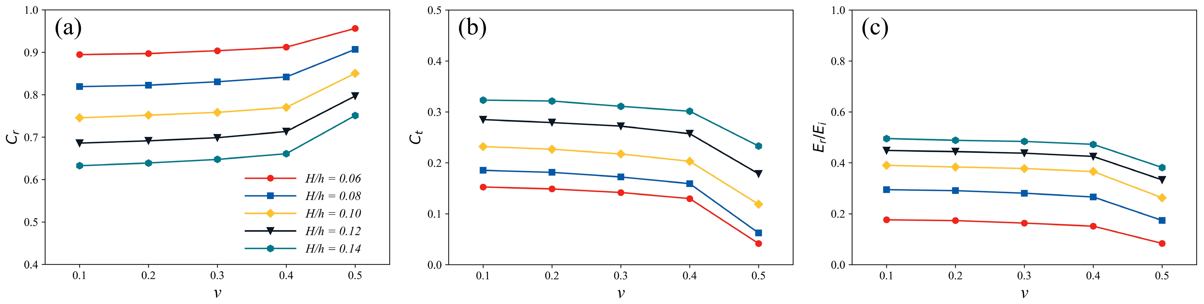
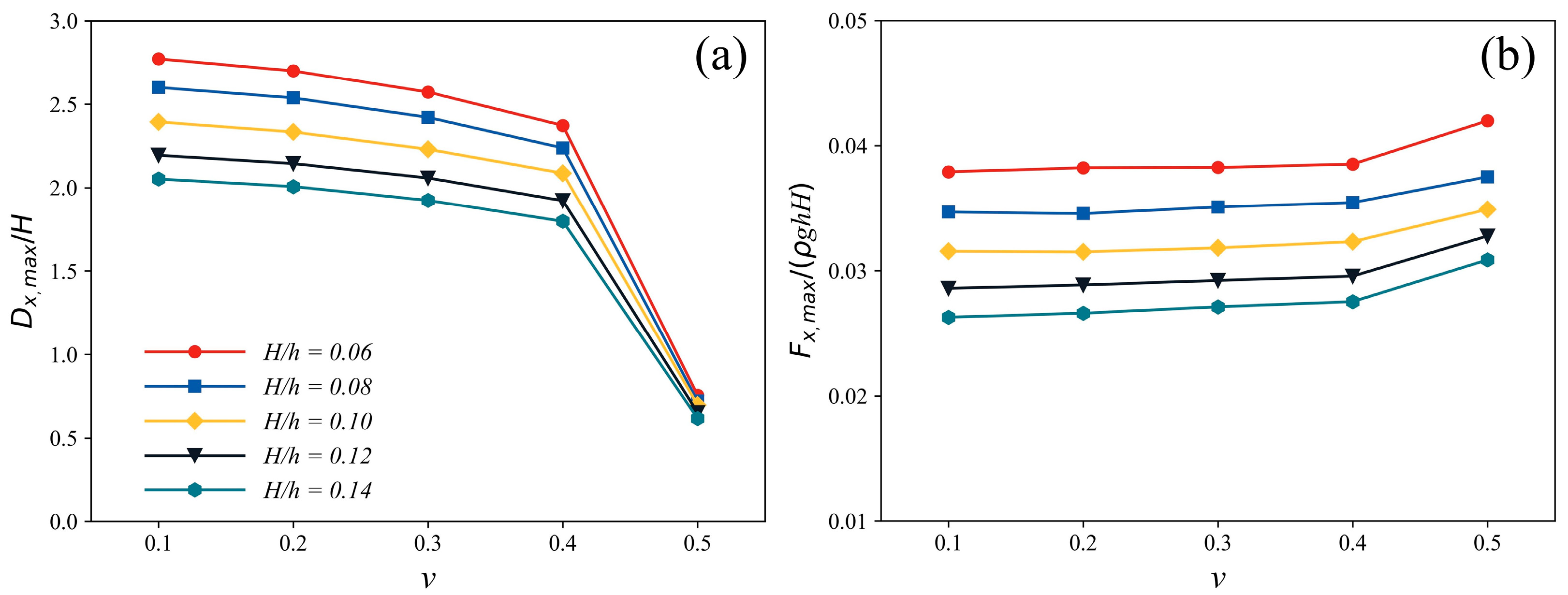
3.3. Effects of Poisson’s Ratio

Poisson’s ratio represents the compressibility of material, which is also a prominent factor for the performance of the flexible breakwater. This part selected varying Poisson’s ratios ( v ) as 0.1, 0.2, 0.3, 0.4, and 0.5, while keeping the still water depth ( h ), the mass coefficient ( γ ), and the stiffness coefficient ( β ) as 0.3 m, 0.08, and 0.1, respectively. Figure 9 presents how the reflection coefficient, transmission coefficient, and wave energy attenuation ratio vary with different values of Poisson’s ratios. It was found that an increase in Poisson’s ratio resulted in a nonlinear enhancement in wave reflection and a decrease in wave transmission. Specifically, at a Poisson’s ratio of 0.5, indicating an incompressible material, the reflection coefficient reached its maximum, and the transmission coefficient its minimum. The change in these coefficients was relatively minor when 0.1 < v < 0.4 , intensifying markedly when it approached 0.5. The minimal dissipation in wave energy was observed when v was equal to 0.5, highlighting the effectiveness of compressible materials in breakwater construction. Furthermore, as depicted in Figure 9c, the attenuation of solitary wave energy due to the dynamic feedback of the flexible breakwater enhanced as there is a decrease in Poisson’s ratio. Figure 10 shows the impact of varying Poisson’s ratios on the maximum horizontal tip displacement and wave load experienced on the flexible breakwater. There was a slight decrease in normalized maximum horizontal displacement adjusting the value of v from 0.1 to 0.4 gradually. From 0.4 to 0.5, a more substantial decrease was observed. Poisson’s ratio had a quite small influence on the maximum horizontal wave load within the range of 0.1 to 0.4; however, there was a significant increase while the value of v varied from 0.4 to 0.5. These findings indicate that the flexible breakwater with lower Poisson’s ratio is more advantageous for reducing solitary wave energy and safeguarding itself against solitary wave impacts. It is also revealed that the flexible breakwater made with incompressible materials suffered from greater wave forces and experienced less deformation compared to those made with compressible materials. All results recommended compressible materials for the construction of flexible breakwaters.

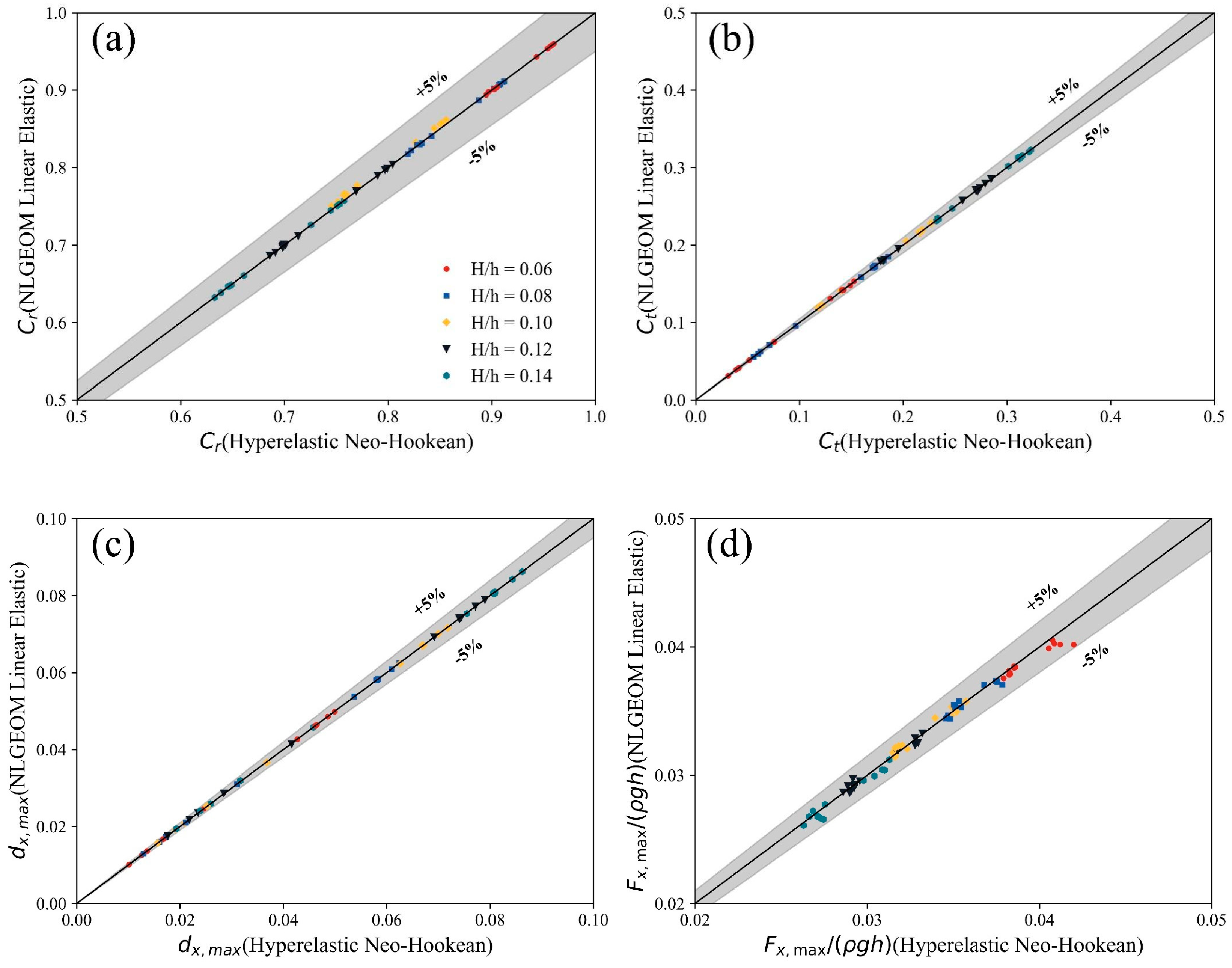
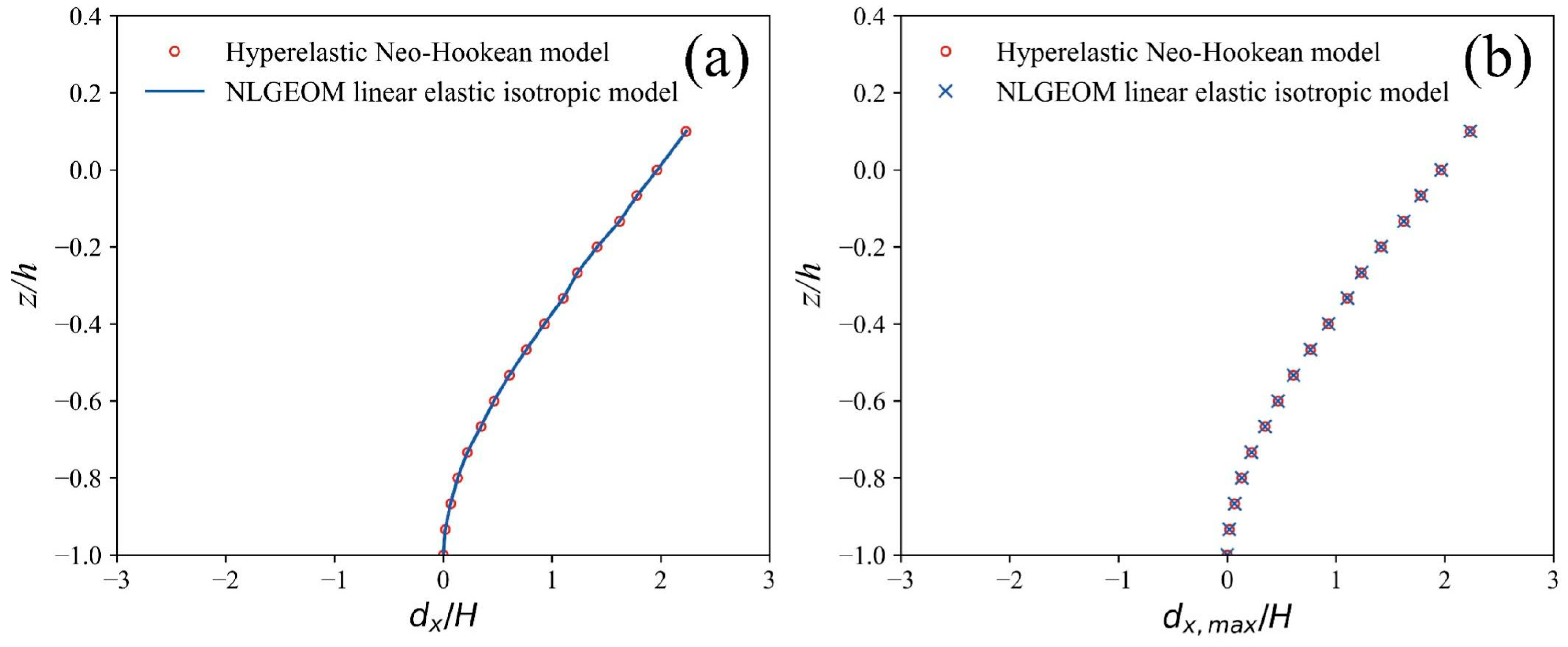
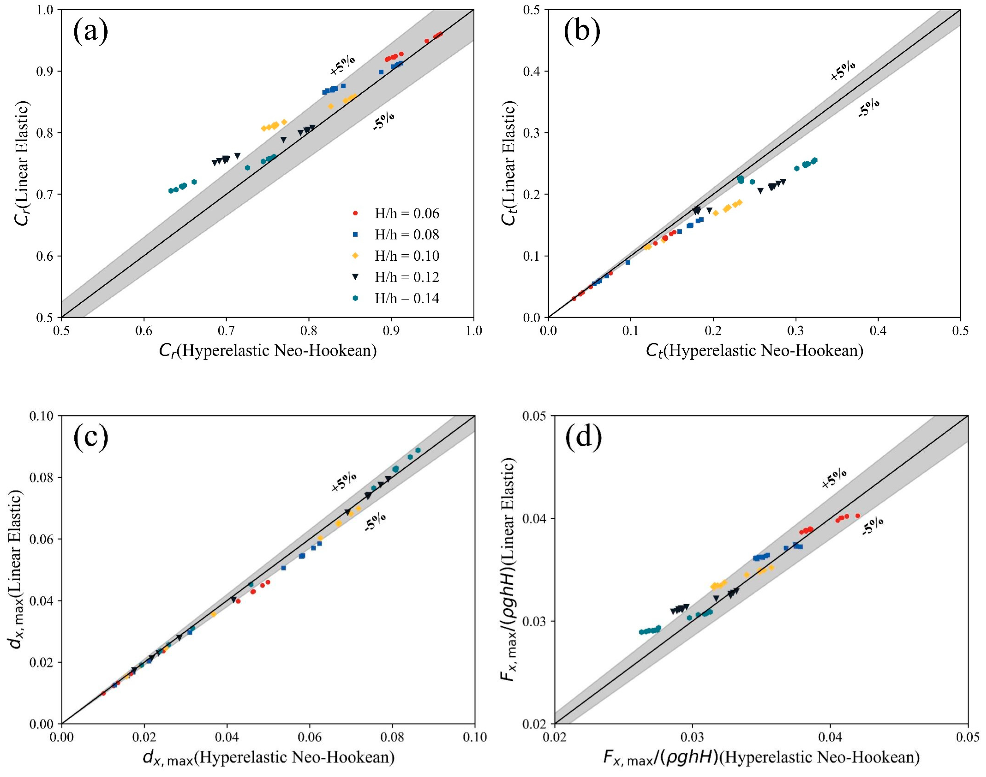
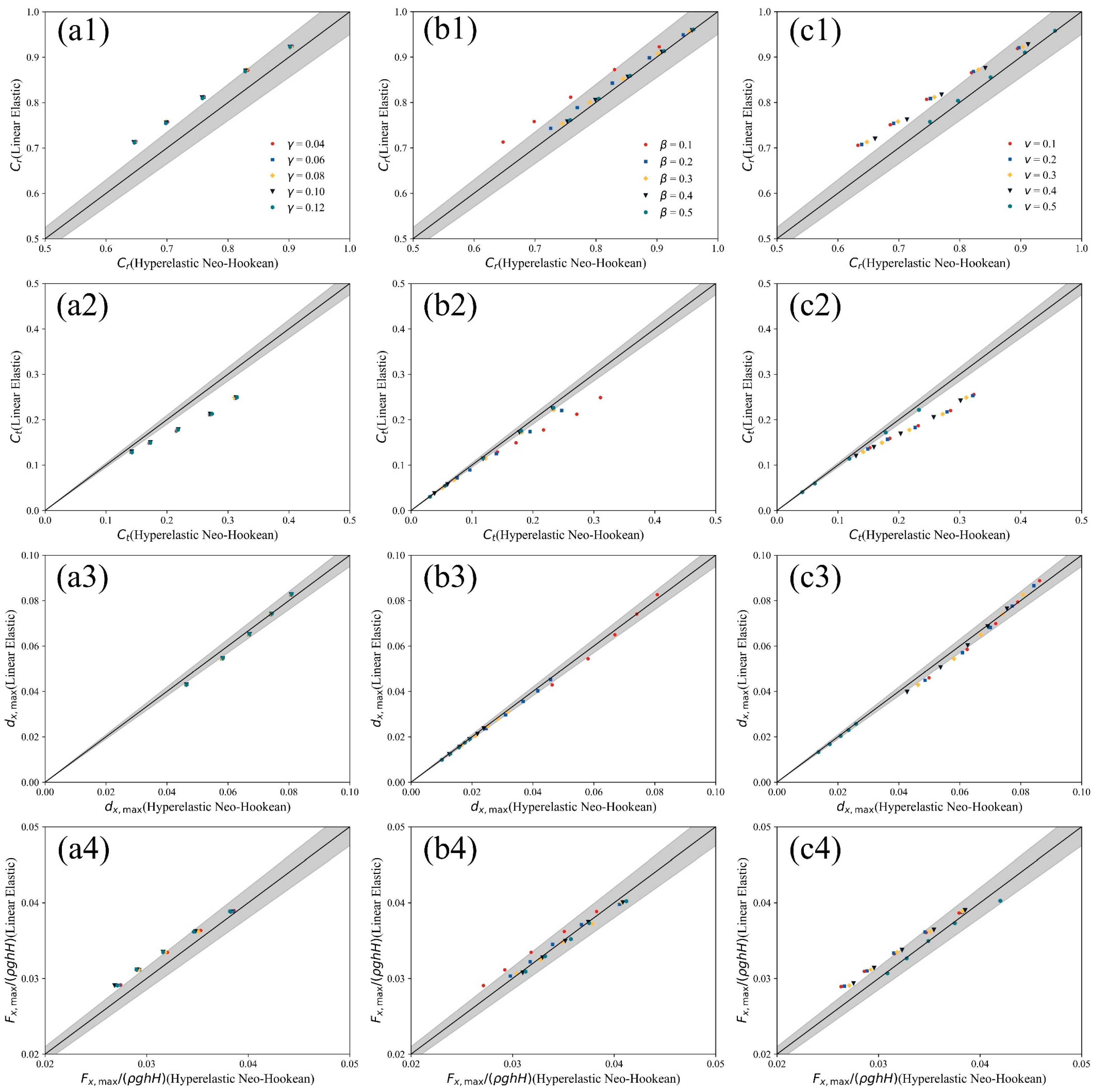
3.4. Comparisons of Three Elastic Material Models

This section presents a comparative analysis of the hyperelastic neo-Hookean material model against the linear elastic isotropic material model with linear and nonlinear geometry analysis. The comparison is based on several critical evaluation metrics, including the reflection coefficient, transmission coefficient, maximum horizontal displacement, and wave load, as illustrated in Figure 11. A total of 65 comparative cases were systematically analyzed to highlight the differences between them.
For these two nonlinear elastic models, they exhibited similar performance in predicting wave reflection, wave transmission, and maximum tip displacement. There was a slight difference in the maximum wave load on the structure, with an error margin within ±5%. This discrepancy is attributed to the high-frequency components of horizontal wave loads influencing the selection of the maximum value. To further explore the differences in horizontal displacement distribution between two materials, Case 3 ( H = 0.03   m ) was examined in detail as a representative example. Figure 12a,b present a comparative analysis of the horizontal displacement distribution along the vertical breakwater at peak tip displacement for both nonlinear elastic models, including the maximum horizontal displacement at all observed points. The results indicate that both materials exhibit almost identical horizontal displacement distributions along the vertical breakwater. In conclusion, the hyperelastic neo-Hookean material model demonstrates comparable performance to the linear elastic isotropic material model with NLGEOM in terms of wave attenuation, structural deformation, and load across these 65 cases. This similarity is likely due to the limited influence of stress–strain relationship under conditions of low stress and strain. Therefore, the nearly consistent performance of the two materials may be attributed to the small wave loads, which do not cause large strain in the structure. The findings further demonstrate that the effect of material nonlinearity on the efficacy of a flexible breakwater in mitigating solitary wave impacts and on its structural responses is negligible within the specified stress–strain parameters.
In the following part, the performance of the hyperelastic neo-Hookean material model was compared with the linear elastic isotropic material model with LGEOM. Figure 13 and Figure 14 present comparative analysis on the above four prominent assessment indicators under different incident wave heights, Poisson’s ratios, stiffness, and mass coefficients. It is obvious that there are significant differences between two elastic materials. In Figure 13a,b, the linear elastic isotropic material model with LGEOM demonstrates increased wave reflection and diminished wave transmission compared to the hyperelastic neo-Hookean material model. More significant differences between these two elastic models can be captured with the increasing wave height. As shown in Figure 14(a1)–(a4) the effect of mass coefficient is negligible on performance differences between them. Figure 14(b1),(b2),(c1),(c2) depicts that the differences in wave reflection and transmission coefficients between these two elastic materials become larger as stiffness coefficient and Poisson’s ratio decrease. But they show the same performance on wave reflection and transmission when the stiffness coefficients and Poisson’s ratios are large enough. The reason for this phenomenon is that hyperelastic neo-Hookean material usually experiences larger strains than linear elastic isotropic material, which can be observed in Figure 13c and Figure 14(b3),(c3). However, the strains in both materials are almost the same when the stiffness coefficients and Poisson’s ratios are large enough. Because it is difficult to deform the material with large stiffness coefficient and Poisson’s ratio. In addition, linear elastic isotropic material with LGEOM suffered larger strain than hyperelastic neo-Hookean material when wave load on the structure exceeds an extremely large value. The opposite is true if it is within the range of extreme values. This phenomenon is very consistent with the changing trend of the stress–strain relationship of the two elastic materials. From Figure 13d and Figure 14(b4),(c4), it is found that there are three situations for generating a large wave load on structure. They are large incident wave height, stiffness coefficient and Poisson’s ratio respectively. Figure 15 plots comparative analysis of the horizontal displacement distribution along the vertical breakwater at peak tip displacement for both materials, including the maximum horizontal displacement at all observed points. It also uses (Case 3 H = 0.03   m ) as an example to show the differences on displacement distribution characteristics. In Figure 15a,b, the difference between two elastic materials becomes more obvious from the bottom to the top of the vertical plate-type flexible breakwater gradually. At all positions, the hyperelastic neo-Hookean material experienced a little larger strain.

4. Conclusions

This research carried out a numerical analysis to assess the wave attenuation capabilities of a vertical plate-type flexible breakwater constructed from hyperelastic neo-Hookean material, subjected to the impacts of a solitary wave. The analysis was facilitated through the deployment of an FVM–FEM coupling model, integrating the functionalities of waves2Foam, preCICE, and CalculiX. We systematically investigated the wave attenuation performance and structural responses of breakwaters utilizing the hyperelastic neo-Hookean material model, with a particular focus on three critical factors: mass coefficient, stiffness coefficient, and Poisson’s ratio. The efficiency of the hyperelastic neo-Hookean material model was evaluated through a comparative analysis against the linear elastic isotropic material model, employing both linear and nonlinear geometric analysis. This comparative assessment was anchored on four critical evaluative metrics: wave reflection coefficient, transmission coefficient, horizontal tip displacement, and wave-induced load on a vertical plate-type flexible breakwater structure. The main findings of this study are outlined below:
(1) In terms of effects of mass, stiffness coefficients, and Poisson’s ratio on solitary wave attenuation performance of a vertical plate-type flexible breakwater, the hyperelastic neo-Hookean material model shows almost the same tendency but differs on specific values with the linear elastic isotropic material model with LGEOM. Compressible and flexible materials are recommended to be used to construct flexible breakwaters due to the higher efficiency on mitigating solitary wave energy and protecting the breakwater from wave damage. In addition, the density of material has a negligible effect on the above behaviors of flexible breakwaters from the perspective of current cases;
(2) The hyperelastic neo-Hookean material model presents almost the same performance on wave reflection, transmission, attenuation, and elastic deformation of a vertical plate-type flexible breakwater with linear elastic isotropic material model coupled with NLGEOM. This similarity is not only shown in the variation tendency but also specific values of evaluation indictors. The findings further demonstrate that the effect of material nonlinearity on the efficiency of a flexible breakwater in mitigating solitary wave impacts and on its structural responses is negligible within the specified stress–strain parameters;
(3) Notable differences exist between the hyperelastic neo-Hookean material model and the linear elastic isotropic material model with LGEOM. The hyperelastic neo-Hookean material demonstrates nonlinear elastic effects on structural deformation, characterized by its nonlinear stress–strain relationship. But, this nonlinear elastic effect is just shown on the structure geometry nonlinearity rather than material nonlinearity, under the range of stress and strain in this study. In contrast, the linear elastic isotropic material with LGEOM is unable to accurately capture the nonlinear variations in structural geometry and the stress–strain relationship. This limitation leads to both the underestimation and overestimation of horizontal tip displacement under conditions of moderate and extreme wave loads, respectively. Furthermore, it tends to underestimate the potential damage from solitary waves, due to inaccuracies in predicting wave reflection and transmission.
Overall, employing the hyperelastic neo-Hookean material model extends our FSI-coupled model from small strain to large strain of structure. It can not only consider the structure geometry nonlinearity but also the material nonlinearity, which makes the structure response closer to actual engineering practice. Furthermore, we highly recommend a more flexible and compressible material to construct the breakwater, which is more effective at mitigating solitary wave energy and is beneficial to protecting the breakwater from wave damage. This paper has further enhanced our understanding on solitary wave attenuation mechanics by flexible breakwaters under nonlinear elastic analysis and made contributions to the design of flexible breakwaters in actual engineering. However, there are also some limitations of this study. As is known, the vertical plate-type flexible breakwater was just adapted to shallow water region. In order to utilize ocean space efficiently, setting up a flexible barrier system along the water depth is better for us to enhance the capability of resisting wave damage. In the future, we will conduct research on developments of innovative flexible breakwater such as membrane breakwaters and space layout of flexible barrier system. In addition, we will also carry out investigations on the regular and irregular wave attenuation performance of these flexible breakwaters to shift the perspective to real ocean conditions and not just focus on extreme situations such as tsunamis.

Author Contributions

Conceptualization, W.S. and T.N.; methodology, W.S. and T.N.; software, W.S. and T.N.; validation, W.S.; formal analysis, W.S.; investigation, W.S. and T.N.; resources, W.S. and T.N.; data curation, W.S.; writing—original draft preparation, W.S.; writing—review and editing, T.N., Y.C. and N.M.; visualization, W.S.; supervision, T.N. and N.M.; project administration, T.N.; funding acquisition, T.N. All authors have read and agreed to the published version of the manuscript.

Funding

This study was sponsored by the Ministry of Education, Culture, Sports, Science and Technology (MEXT), Japan.

Institutional Review Board Statement

Not applicable.

Informed Consent Statement

Not applicable.

Data Availability Statement

No new data were created or analyzed in this study. Data sharing is not applicable to this article.

Acknowledgments

The authors are grateful to the team members of OpenFOAM, CalculiX, and preCICE.

Conflicts of Interest

The authors declare no conflicts of interest. The funders had no role in the design of the study; in the collection, analyses, or interpretation of data; in the writing of the manuscript; or in the decision to publish the results.

References

  1. Tanaka, M.; Ohyama, T.; Kiyokawa, T.; Uda, T.; Omata, A. Characteristics of wave dissipation by flexible submerged breakwater and utility of the device. In Coastal Engineering 1992; American Society of Civil Engineers: Reston, VA, USA, 1993; pp. 1613–1624. [Google Scholar]
  2. Guo, Y.C.; Mohapatra, S.C.; Guedes Soares, C. Experimental study on the performance of an array of vertical flexible porous membrane type breakwater under regular waves. Ocean Eng. 2022, 264, 112328. [Google Scholar] [CrossRef]
  3. Loukogeorgaki, E.; Yagci, O.; Kabdasli, M.S. 3D Experimental investigation of the structural response and the effectiveness of a moored floating breakwater with flexibly connected modules. Coast. Eng. 2014, 91, 164–180. [Google Scholar] [CrossRef]
  4. Loukogeorgaki, E.; Lentsiou, E.N.; Aksel, M.; Yagci, O. Experimental investigation of the hydroelastic and the structural response of a moored pontoon-type modular floating breakwater with flexible connectors. Coast. Eng. 2017, 121, 240–254. [Google Scholar] [CrossRef]
  5. Sree, D.K.K.; Mandal, S.; Law, A.W.K. Surface wave interactions with submerged horizontal viscoelastic sheets. Appl. Ocean Res. 2021, 107, 102483. [Google Scholar] [CrossRef]
  6. Hsiao, Y.; Hsiao, S.C. Experimental study on the interaction of solitary wave with elastic submerged plate. Ocean Eng. 2022, 261, 112106. [Google Scholar] [CrossRef]
  7. Abul-Azm, A.G. Wave diffraction through submerged flexible breakwaters. Ocean Eng. 1996, 23, 403–422. [Google Scholar] [CrossRef]
  8. Peter, M.A.; Meylan, M.H. A general spectral approach to the time-domain evolution of linear water waves impacting on a vertical elastic plate. SIAM J. Appl. Math. 2010, 70, 2308–2328. [Google Scholar] [CrossRef]
  9. Lan, Y.J.; Hsu, T.W.; Lai, J.W.; Chang, C.C.; Ting, C.H. Bragg scattering of waves propagating over a series of poro-elastic submerged breakwaters. Wave Motion 2011, 48, 1–12. [Google Scholar] [CrossRef]
  10. Li, A.J.; Liu, Y.; Liu, X.; Zhao, Y. Analytical and experimental studies on Bragg scattering of water waves by multiple submerged perforated semi-circular breakwaters. Ocean Eng. 2020, 209, 107419. [Google Scholar] [CrossRef]
  11. Das, S.; Cheung, K.F. Coupled boundary element and finite element model for fluid-filled membrane in gravity waves. Eng. Anal. Bound. Elem. 2009, 33, 802–814. [Google Scholar] [CrossRef]
  12. Liao, K.; Hu, C. A coupled FDM–FEM method for free surface flow interaction with thin elastic plate. J. Mar. Sci. Technol. 2013, 18, 1–11. [Google Scholar] [CrossRef]
  13. Zhao, X.; Zhou, Y.; Zong, Y.; Yang, Z.; Luo, M. A CIP-based numerical simulation of wave interaction with a fluid-filled membrane submerged breakwater. Ocean Eng. 2022, 260, 111819. [Google Scholar] [CrossRef]
  14. Tuković, Ž.; Karač, A.; Cardiff, P.; Jasak, H.; Ivanković, A. OpenFOAM finite volume solver for fluid-solid interaction. Trans. FAMENA 2018, 42, 1–31. [Google Scholar] [CrossRef]
  15. Cardiff, P.; Karač, A.; De Jaeger, P.; Jasak, H.; Nagy, J.; Ivanković, A.; Tuković, Ž. An open-source finite volume toolbox for solid mechanics and fluid-solid interaction simulations. arXiv 2018, arXiv:1808.10736. [Google Scholar]
  16. Huang, L.; Ren, K.; Li, M.; Tuković, Ž.; Cardiff, P.; Thomas, G. Fluid-structure interaction of a large ice sheet in waves. Ocean Eng. 2019, 182, 102–111. [Google Scholar] [CrossRef]
  17. Huang, L.; Li, Y. Design of the submerged horizontal plate breakwater using a fully coupled hydroelastic approach. Comput.-Aided Civ. Infrastruct. Eng. 2022, 37, 915–932. [Google Scholar] [CrossRef]
  18. Hu, Z.; Huang, L.; Li, Y. Fully-coupled hydroelastic modeling of a deformable wall in waves. Coast. Eng. 2022, 179, 104245. [Google Scholar] [CrossRef]
  19. Bungartz, H.J.; Lindner, F.; Gatzhammer, B.; Mehl, M.; Scheufele, K.; Shukaev, A.; Uekermann, B. preCICE—A fully parallel library for multi-physics surface coupling. Comput. Fluids 2016, 141, 250–258. [Google Scholar] [CrossRef]
  20. Dhondt, G. The Finite Element Method for Three-Dimensional Thermomechanical Applications; John Wiley & Sons: Hoboken, NJ, USA, 2004. [Google Scholar]
  21. Vilmar, F. Numerische Modellierung von Fluid-Struktur-Wechselwirkungen an Wellenbeaufschlagten Strukturen. Ph.D. Thesis, Universität Kassel, Fachbereich Maschinenbau, Kassel, Germany, 2014. [Google Scholar]
  22. Sun, W.Y.; Nakamura, T.; Cho, Y.H.; Mizutani, N. Numerical investigation of solitary wave attenuation by a vertical plate-type flexible breakwater using an FVM–FEM coupled model. Part 1: Linear elastic isotropic material. Ocean Eng. 2023, 285, 115368. [Google Scholar] [CrossRef]
  23. Jacobsen, N.G. Waves2foam Manual; Deltares: Delft, The Netherlands, 2017; p. 570. [Google Scholar]
  24. Hirt, C.W.; Nichols, B.D. Volume of fluid (VOF) method for the dynamics of free boundaries. J. Comput. Phys. 1981, 39, 201–225. [Google Scholar] [CrossRef]
  25. Weller, H.G.; Tabor, G.; Jasak, H.; Fureby, C. A tensorial approach to computational continuum mechanics using object-oriented techniques. Comput. Phys. 1998, 12, 620–631. [Google Scholar] [CrossRef]
  26. Jacobsen, N.G.; Fuhrman, D.R.; Fredsøe, J. A wave generation toolbox for the open-source CFD library: OpenFoam®. Int. J. Numer. Methods Fluids 2012, 70, 1073–1088. [Google Scholar] [CrossRef]
  27. Uekermann, B.; Bungartz, H.; Yau, L.C.; Chourdakis, G.; Rusch, A. Official preCICE Adapters for Standard Open-Source Solvers. In Proceedings of the 7th GACM Colloquium on Computational Mechanics for Young Scientists from Academia, Stuttgart, Germany, 11–13 October 2017. [Google Scholar]
  28. Haelterman, R.; Bogaers, A.E.J.; Scheufele, K.; Uekermann, B.; Mehl, M. Improving the performance of the partitioned QN-ILS procedure for fluid–structure interaction problems: Filtering. Comput. Struct. 2016, 171, 9–17. [Google Scholar] [CrossRef]
  29. Lindner, F.; Mehl, M.; Uekermann, B. Radial basis function interpolation for black-box multi-physics simulations. In Proceedings of the VII International Conference on Computational Methods for Coupled Problems in Science and Engineering (COUPLED 2017), Rhodes Island, Greece, 12–14 June 2017. [Google Scholar]
Figure 1. The layout for the numerical wave tank.
Jmse 12 01004 g001
Figure 2. The diagram of interface coupling.
Jmse 12 01004 g002
Figure 3. The framework of the coupled algorithm.
Jmse 12 01004 g003
Figure 4. Numerical layout for interactions between a solitary wave and a vertical plate-type flexible breakwater.
Jmse 12 01004 g004
Figure 5. Variations at different mass coefficients γ : (a) reflection coefficient C r , (b) transmission coefficient C t , (c) wave energy attenuation ratio E r / E i .
Jmse 12 01004 g005
Figure 6. Variations of flexible breakwaters at different mass coefficients γ : (a) normalized maximum horizontal tip displacement D x , m a x / H , (b) normalized maximum horizontal wave load F x , m a x / ρ g h H .
Jmse 12 01004 g006
Figure 7. Variations at different stiffness coefficients β : (a) reflection coefficient C r , (b) transmission coefficient C t , (c) wave energy attenuation ratio E r / E i .
Jmse 12 01004 g007
Figure 8. Variations of flexible breakwater at different stiffness coefficients β : (a) normalized maximum horizontal tip displacement D x , m a x / H , (b) normalized maximum horizontal wave load F x , m a x / ρ g h H .
Jmse 12 01004 g008
Figure 9. Variations at different Poisson’s ratios ν : (a) reflection coefficient C r , (b) transmission coefficient C t , (c) wave energy attenuation ratio E r / E i .
Jmse 12 01004 g009
Figure 10. Variations of flexible breakwater at different Poisson’s ratios ν : (a) normalized maximum horizontal tip displacement D x , m a x / H , (b) normalized maximum horizontal wave load F x , m a x / ρ g h H .
Jmse 12 01004 g010
Figure 11. Comparative analysis between linear elastic isotropic material with NLGEOM and hyperelastic neo-Hookean material performance across four prominent evaluation indices: (a) reflection coefficient; (b) transmitted coefficient; (c) maximum horizontal displacement; (d) maximum horizontal wave force.
Jmse 12 01004 g011
Figure 12. Comparative analysis between linear elastic isotropic material with NLGEOM and hyperelastic neo-Hookean material on (a) the horizontal displacement distribution along the vertical breakwater when tip displacement reached the maximum value, and (b) the maximum horizontal displacement of all observed points.
Jmse 12 01004 g012
Figure 13. Comparative analysis between a linear elastic isotropic material with LGEOM and hyperelastic neo-Hookean material performance under different wave heights across four prominent evaluation indices: (a) reflection coefficient, (b) transmitted coefficient, (c) maximum horizontal displacement, and (d) maximum horizontal wave force.
Jmse 12 01004 g013
Figure 14. Comparative analysis between a linear elastic isotropic material with LGEOM and hyperelastic neo-Hookean material performance under different (a) mass coefficients, (b) stiffness coefficients, and (c) Poisson’s ratios across four prominent evaluation indices: (a1,b1,c1) reflection coefficient, (a2,b2,c2) transmitted coefficient, (a3,b3,c3) maximum horizontal displacement, and (a4,b4,c4) maximum horizontal wave force.
Jmse 12 01004 g014
Figure 15. Comparative analysis between a linear elastic isotropic material with LGEOM and hyperelastic neo-Hookean material on (a) the horizontal displacement distribution along the vertical breakwater when tip displacement reached the maximum value, and (b) the maximum horizontal displacement of all observed points.
Jmse 12 01004 g015
Table 1. Computational parameters of structure and wave properties.
CaseStructure PropertiesWave Properties
ρ s   ( k g / m 3 ) E   ( G P a ) v γ β H   ( m ) h   ( m )
16000.0120.30.040.10.018

0.024

0.030

0.036

0.042
0.3
29000.0120.30.060.1
312000.0120.30.080.1
415000.0120.30.100.1
518000.0120.30.120.1
612000.0240.30.080.2
712000.0360.30.080.3
812000.0480.30.080.4
912000.0600.30.080.5
1012000.0120.10.080.1
1112000.0120.20.080.1
1212000.0120.40.080.1
1312000.0120.50.080.1
Disclaimer/Publisher’s Note: The statements, opinions and data contained in all publications are solely those of the individual author(s) and contributor(s) and not of MDPI and/or the editor(s). MDPI and/or the editor(s) disclaim responsibility for any injury to people or property resulting from any ideas, methods, instructions or products referred to in the content.

