Article

Free and Forced Vibration Characteristics of a Composite Stiffened Plate Based on Energy Method

1
School of Naval Architecture, Ocean and Energy Power Engineering, Wuhan University of Technology, Wuhan 430063, China
2
Green & Smart River-Sea-Going Ship, Cruise Ship and Yacht Research Center, Wuhan University of Technology, Wuhan 430063, China
3
School of Science, Wuhan University of Technology, Wuhan 430070, China
4
Jiangsu Branch China Classification Society, Nanjing 210011, China
*
Author to whom correspondence should be addressed.
J. Mar. Sci. Eng. 2024, 12(6), 875; https://doi.org/10.3390/jmse12060875
Submission received: 19 April 2024 / Revised: 21 May 2024 / Accepted: 23 May 2024 / Published: 24 May 2024
(This article belongs to the Section Ocean Engineering)

Abstract

:
The composite stiffened plate has garnered significant attention in the lightweight design of ship structures due to its superior mechanical properties. Although it reduces the structural weight, it also increases vibration sensitivity. Thus, investigating the vibration characteristics of the composite stiffened plate is crucial. This paper proposed a theoretical model based on the energy principle and the improved Fourier series method (IFSM) to analyze the composite stiffened plate vibration characteristics. The model demonstrates high reliability and accuracy, as confirmed through convergence analysis and comparison with experimental results from the published literature. Results indicate that geometry and material parameters significantly impact the natural frequency and can mitigate vibration responses by increasing thickness and stiffness. Additionally, ply design parameters markedly influence the vibration of composite stiffened plates, enhancing low-frequency vibration performance through optimal ply design. The structural parameters of the stiffeners, particularly the height and number of stiffeners, play a crucial role, enhancing stiffness and reducing the vibration responses of the composite stiffened plates.

1. Introduction

With rapid social progress and deepening globalization, governments are focusing on energy consumption and environmental protection. Specific requirements for energy conservation and emission reduction have been proposed with the aim of addressing climate change and promoting the realization of sustainable development. Shipping is one of the main sources of energy consumption and emissions in the transportation industry, thus presenting new requirements and challenges for the ship’s structural design. Lightweight structural design can effectively control the weight and gravity of the ship structure, which can not only improve navigational performance, but also reduce energy consumption and emissions. The Swedish government launched the LASS project and the LASS-C project [1,2], which focus on the development and application of composite materials in ship structural design. Composite materials are used in the structural design of ship superstructures such as a high-speed craft, a Ro-Pax ferry, and a cruise ship. The project investigates the application of composite materials in modern ship engineering from the technical, economic feasibility, and safety perspectives. The application of composite materials in ship engineering reduces the weight of hull structures, effectively lowers energy consumption, and enhances operational efficiency, providing new directions for future ship design and construction.
The composite stiffened plate combines the advantages of stiffened plate and composite material, offering significant advantages in lightweight ship design by meeting structural loading requirements while reducing the structural weight. However, the structural weight reduction typically heightens the sensitivity to structural vibration, and the use of composite materials introduces complexity to the vibration characteristics. Extensive research has been conducted on stiffened plate vibration, including the finite difference method [3], the spline composite strip method [4], the finite element method (FEM) [5], and the Rayleigh–Ritz method [6]. Peng et al. [7] developed a meshless theoretical model based on the first-order shear deformation theory (FSDT) to analyze the stiffened plate bulking and free vibration characteristics. Cho et al. [8,9,10,11,12] developed the VAPS software based on the assumed modal method to simulate the free and forced vibrations of the stiffened plate and explore the impact of different topologies, attachments, and arbitrary boundary conditions. Qin et al. [13] proposed an analytical model to investigate the static and dynamic characteristics of curvilinearly stiffened plates. Zhang and Lin [14] investigated Mindlin stiffened plate vibration characteristics based on the modal expansion method. Sahoo [15,16] applied the FEM to study the stiffened plate free vibration and the dynamic response under moving loads. Liu [17] proposed a theoretical model to examine the free vibration in stiffened plates with arbitrary cross-section beams. Qin et al. [18] established a meshless theoretical analytical model to analyze the circular stiffened plate structure bending and free vibration. Zhang et al. [19] presented an analytical solution for the rectangular orthogonal stiffened plate vibration response. Liu et al. [20] introduced a dynamic analysis method for stiffened plates under moving loads utilizing the FSDT along with Chebyshev polynomials for spatial discretization and penalty functions for various boundary conditions. Ko and Boo [21] proposed a condensed finite element matrix using the iterated improved reduced system (IIRS) method to address modal, frequency, and transient responses of stiffened plates. Guo et al. [22] investigated the concentric stiffened plate free vibration using a two-dimensional spectral Chebyshev technique. Shen et al. [23] proposed a meshless approach for analyzing the stiffened plate free and forced vibration and conducted structural vibration experiments. Wang [24] explored the free vibration of rectangular stiffened plates with cutouts. Gao et al. [25] developed a semi-analytical approach based on the domain decomposition method (DDM) to study the dynamic behavior of the stiffened plate under various conditions, complemented by experimental validations. Chen et al. [26] conducted an experimental study on the stiffened plate vibro-acoustic characteristics under various welding conditions.
Composite stiffened plate vibration characteristics have attracted extensive research due to their special structure and complex mechanical properties. Rikards et al. [27] explored the buckling and vibration characteristics of composite stiffened plates using the FEM. Ahmadian et al. [28] applied the super elements method to analyze the free vibration characteristics of the laminated stiffened plate with eccentric stiffeners. Qing et al. [29] developed a semi-analytical solution model for the laminate stiffened plate free vibration. Nayak and Bandyopadhyay [30] utilized the FEM to study the free vibration of doubly curved stiffened laminated shells. Prusty and Ray [31,32] analyzed the free vibration and buckling characteristics of composite stiffened plates and shells with various cross-section stiffeners using the FEM. Thinh and Quoc [33] used the FEM and experimental methods to study the composite stiffened plate buckling and vibration with various cross-section stiffeners. Mejdi and Atalla [34] proposed a semi-analytical model based on the modal expansion technique for the vibro-acoustic analysis of the composite stiffened plate. Damnjanović et al. [35,36] introduced a dynamic stiffness approach utilizing the FSDT and the HSDT (higher-order shear deformation theory) to analyze the stiffened and cracked laminated plate free vibration. Zhao and Kapania [37] developed an effective FEM to analyze the pre-stress vibration of curvilinearly stiffened composite plates under in-plane loads. Sinha et al. [38,39,40] conducted numerical and experimental studies on the free vibration of glass–fiber laminated composite stiffened plates. Chandra et al. [41,42] investigated the damping and structural dynamic responses of composite stiffened plates in a thermal environment. Wang et al. [43] formulated an analytical model for the structural dynamic characteristics of stiffened composite sandwich plates embedded with multilayer viscoelastic damping membranes and validated this model through a comparison with FEM results. Peng et al. [44] introduced a meshless method based on the FSDT to investigate the static and free vibration characteristics of the composite stiffened plate with varying parameters.
The improved Fourier series method (IFSM) is widely used in the vibration analysis of beams, plates, and shells [45,46,47,48,49] due to its advantages in handling boundary conditions and achieving efficient computational convergence. Ye et al. [50,51] developed a unified model using IFSM for the free vibration of laminated composite shallow shells and moderately thick laminated plates under various boundary conditions. Zhang et al. [52] derived a series solution for orthogonal rectangular plate in-plane vibration with elastic constraints using IFSM. Wang et al. [53,54,55,56] applied IFSM to model the vibrations of laminate plates and shells, conducting comprehensive research to explore the effects of material parameters, shell types, and boundary conditions on structural dynamic characteristics. Shi et al. [57] investigated the free and forced vibration of moderately thick laminated plates under multi-point support boundary conditions through IFSM. Zhang et al. [58] studied the moderately thick laminated plate free vibration under non-uniform boundary conditions using IFSM. Cao [59] used IFSM to establish a theoretical model of rectangular stiffened plates with various numbers and lengths of stiffeners, analyzing the dynamic characteristics. Du et al. [60] formulated theoretical models to analyze the stiffened plate free and forced vibration based on IFSM and conducted experiments to validate the accuracy.
Through the above research, it can be found that the researchers focus on the isotropic stiffened plate and composite laminated shell bulking and free vibration characteristics. The study of the composite stiffened plate forced vibration response is also very important. This paper develops a theoretical model based on the FSDT, Timoshenko beam theory, and IFSM to analyze the free and forced vibration of the composite stiffened plate. Numerical examples demonstrate that the theoretical method presented in this paper has good reliability and accuracy. Utilizing this method, the parametric analysis of the composite stiffened plate is conducted, including geometry parameters, material parameters, ply parameters, stiffener parameters, etc. It aims to understand the vibration mechanisms of the composite stiffened plate and provide theoretical support for low-vibration design.

2. Theoretical Formulations

In this paper, the composite stiffened plate is taken as the research object, establishing the theoretical model based on the FSDT and Timoshenko beam theory. The composite stiffened plate is composed of a × b × hp laminate panel and hs × bs laminate stiffener. A global coordinate system o-xyz is established based on the mid-plane xoy, and a local coordinate system o′-x′y′z′ is established based on the neutral axis o′x′, as shown in Figure 1 and Figure 2. up, vp and wp represent the displacements of the composite stiffened plate along the x-, y-, and z-axes, respectively, while φ x and φ y are the rotation around the y- and x-axes. θ is the angle between the kth ply direction and the x-axis. Zk+1 and Zk are the coordinates of the upper and lower surface of the kth ply along the z-axis. The artificial virtual springs uniformly distributed along each side of the composite stiffened plate simulate the boundary conditions. The stiffness values of the linear support springs (ku, kv, and kw) and the twist springs (Kx and Ky) are adjusted to simulate various boundary conditions.

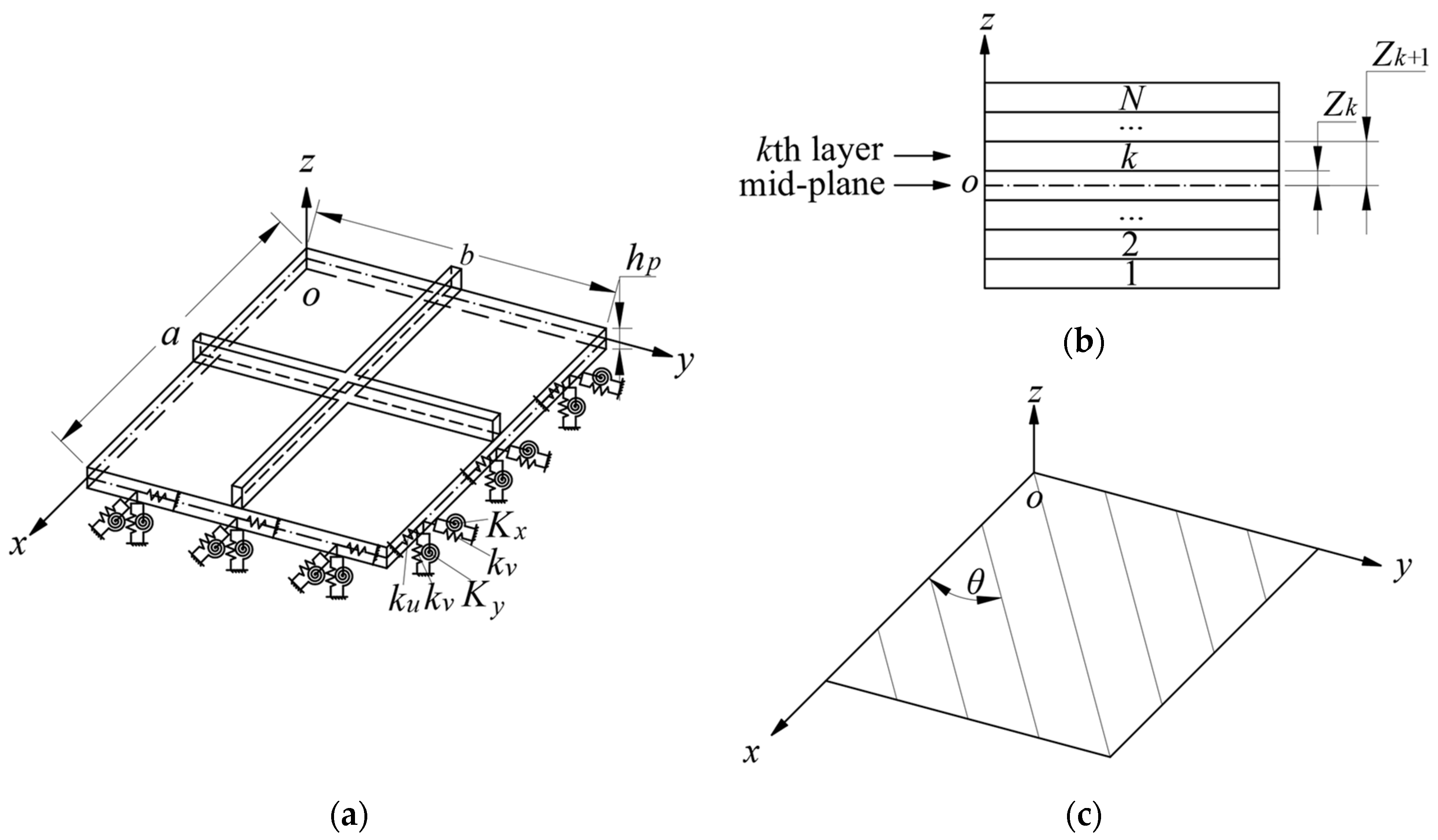
2.1. Kinematics and Stress–Strain Relations

2.1.1. Kinematics and Stress–Strain Relations of Laminate Panel

According to the FSDT, the displacement of the laminate panel is
U x , y , z , t = u p x , y , t + z φ x x , y , t V x , y , z , t = v p x , y , t + z φ y x , y , t W x , y , z , t = w p x , y , t
where up, vp, and wp are the laminate panel displacements along the x-, y-, and z-axes, respectively. φ x and φ y are the rotations around the y- and x-axes. t is the time variable.
The liner strain–displacement relationship for the kth ply of the laminate panel is
ε x x ε y y γ x y = ε x x 0 ε y y 0 γ x y 0 + z χ x x χ y y χ x y
γ x z γ y z = γ x z 0 γ y z 0
where ε x x , ε y y , and γ x y are the in-plane normal strain components of the laminate panel, while γ x z and γ y z are the shear strain components along the panel thickness direction. ε x x 0 , ε y y 0 , and γ x y 0 represent the membrane strains in the mid-plane. χ x x , χ y y , and χ x y represent the changes in the curvature in the mid-plane. γ x z 0 and γ y z 0 are the shear strains in the thickness direction. The relationship expressions are
ε x x 0 ε y y 0 γ x y 0 = u p x v p y u p y + v p x
χ x x χ y y χ x y = φ x x φ y y φ x y + φ y x
γ x z 0 γ y z 0 = w p x + φ x w p y + φ y
According to Hooke’s Law, the stress–strain relationship for the kth ply of the laminate panel is
σ x x σ y y τ x y τ x z τ y z = Q ¯ 11 k Q ¯ 12 k Q ¯ 16 k 0 0 Q ¯ 12 k Q ¯ 22 k Q ¯ 26 k 0 0 Q ¯ 16 k Q ¯ 26 k Q ¯ 66 k 0 0 0 0 0 Q ¯ 55 k Q ¯ 45 k 0 0 0 Q ¯ 45 k Q ¯ 44 k ε x x ε y y γ x y γ x z γ y z
where σ x x and σ y y represent the normal stresses in the x and y directions. τ y z , τ x z , and τ x y represent the shear stresses in x, y, and z directions.
The relationship between stiffness coefficients Q ¯ i j k i , j = 1 , 2 , 4 , 5 , 6 and material coefficients Q i j k i , j = 1 , 2 , 4 , 5 , 6 for kth ply is
Q 11 k ¯ Q 12 k ¯ Q 16 k ¯ Q 22 k ¯ Q 26 k ¯ Q 66 k ¯ = m 4 2 m 2 n 2 n 4 4 m 2 n 2 m 2 n 2 m 4 + n 4 m 2 n 2 4 m 2 n 2 m 3 n m n n 2 m 2 m n 3 2 m n n 2 m 2 n 4 2 m 2 n 2 m 4 4 m 2 n 2 m n 3 m n m 2 n 2 m 3 n 2 m n m 2 n 2 m 2 n 2 2 m 2 n 2 m 2 n 2 m 2 n 2 2 Q 11 k Q 12 k Q 22 k Q 66 k
Q 44 k ¯ Q 45 k ¯ Q 55 k ¯ = m 2 n 2 m n m n n 2 m 2 Q 44 k Q 55 k
where m = cos θ and n = sin θ . θ is the angle between the kth ply direction and the x-axis.
The kth ply material coefficients Q i j k i , j = 1 , 2 , 4 , 5 , 6 are
Q 11 k = E 1 1 μ 12 μ 21 , Q 12 k = μ 21 Q 11 k , Q 22 k = E 2 1 μ 12 μ 21 , Q 44 k = G 23 , Q 55 k = G 13 , Q 66 k = G 12
where E1 and E2 are the longitudinal and transverse moduli. μ12 is the major Poisson’s ratio, μ21 = μ12E1/E2. G12, G13, and G23 are the shear moduli. In the case of isotropic materials, the elastic modulus is E = E1 = E2, and the shear modulus is G = G12 = G13 = G23 = E/2(1 + μ).
Integrating along the thickness direction, the internal forces and bending moments in the laminate panel are
N x N y N x y = k = 1 N z k z k + 1 σ x x σ y y τ x y d z
M x M y M x y = k = 1 N z k z k + 1 σ x x σ y y τ x y z d z
Q x z Q y z = κ k = 1 N z k z k + 1 γ x z γ y z d z
where Nx, Ny, and Nxy represent the in-plane force vectors. Mx, My, and Mxy represent the bending moment vectors. Qx and Qy represent the shear force vectors. κ = 5/6. Substituting Equation (7) into Equations (11)–(13), the relationship between the internal forces and strain components of the laminate panel is
N x N y N x y M x M y M x y = A 11 A 12 A 16 B 11 B 12 B 16 A 12 A 22 A 26 B 12 B 22 B 26 A 16 A 26 A 66 B 16 B 26 B 66 B 11 B 12 B 16 D 11 D 12 D 16 B 12 B 22 B 26 D 12 D 22 D 26 B 16 B 26 B 66 D 16 D 26 D 66 ε x x 0 ε y y 0 γ x y 0 χ x x χ y y χ x y
Q x z Q y z = κ A 55 A 45 A 45 A 44 γ x z γ y z
where Aij, Bij, and Dij are the tensile stiffness, tensile-bending stiffness, and bending stiffness, respectively,
A i j = k = 1 N Q ¯ i j k Z k + 1 Z k i , j = 1 , 2 , 4 , 5 , 6 B i j = 1 2 k = 1 N Q ¯ i j k Z k + 1 2 Z k 2 i , j = 1 , 2 , 6 D i j = 1 3 k = 1 N Q ¯ i j k Z k + 1 3 Z k 3 i , j = 1 , 2 , 6

2.1.2. Kinematics and Stress–Strain Relations of Laminate Stiffener

According to the Timoshenko beam theory, the laminate stiffener displacement is
U s x , z , t = u s x , t + z ϕ x x , t W s x , z , t = w s x , t y ϕ y x , t
where us and ws represent the laminate stiffener displacements along the x’- and z’-axes. ϕ x and ϕ y are the rotations around the y’- and x’-axes.
The strain–displacement relationship for the laminate stiffener is
ε x γ x z = u s x + z ϕ x x w s x y ϕ y x + ϕ x
The stress–strain relationship for the laminate stiffener is
σ x τ x z = Q ˜ 11 k ε x Q ˜ 55 k γ x z
where
Q ˜ 11 k = Q ¯ 11 k Q ¯ 12 k Q ¯ 16 k Q ¯ 22 k Q ¯ 26 k Q ¯ 26 k Q ¯ 66 k 1 Q ¯ 12 k Q ¯ 16 k
Q ˜ 55 k = Q ¯ 55 k Q ¯ 45 k 2 Q ¯ 44 k
when the stiffener is made of isotropic material, Q ˜ 11 k = E , and Q ˜ 55 k = G = E / 2 ( 1 + μ ) .
Considering the eccentricity of the stiffener, the displacement continuity condition is satisfied between the laminate panel and the laminate stiffener. The laminate stiffener displacement can be expressed in terms of the laminate panel.
u s w s ϕ x ϕ y = cos α sin α 0 e cos α e sin α 0 0 1 0 0 0 0 0 cos α sin α 0 0 0 sin α cos α u p v p w p φ x φ y
where α is the angle between the stiffener direction and the x-axis. e is the distance between the laminate panel mid-plane and the stiffener neutral axis, defined as e = (hp + hs)/2.

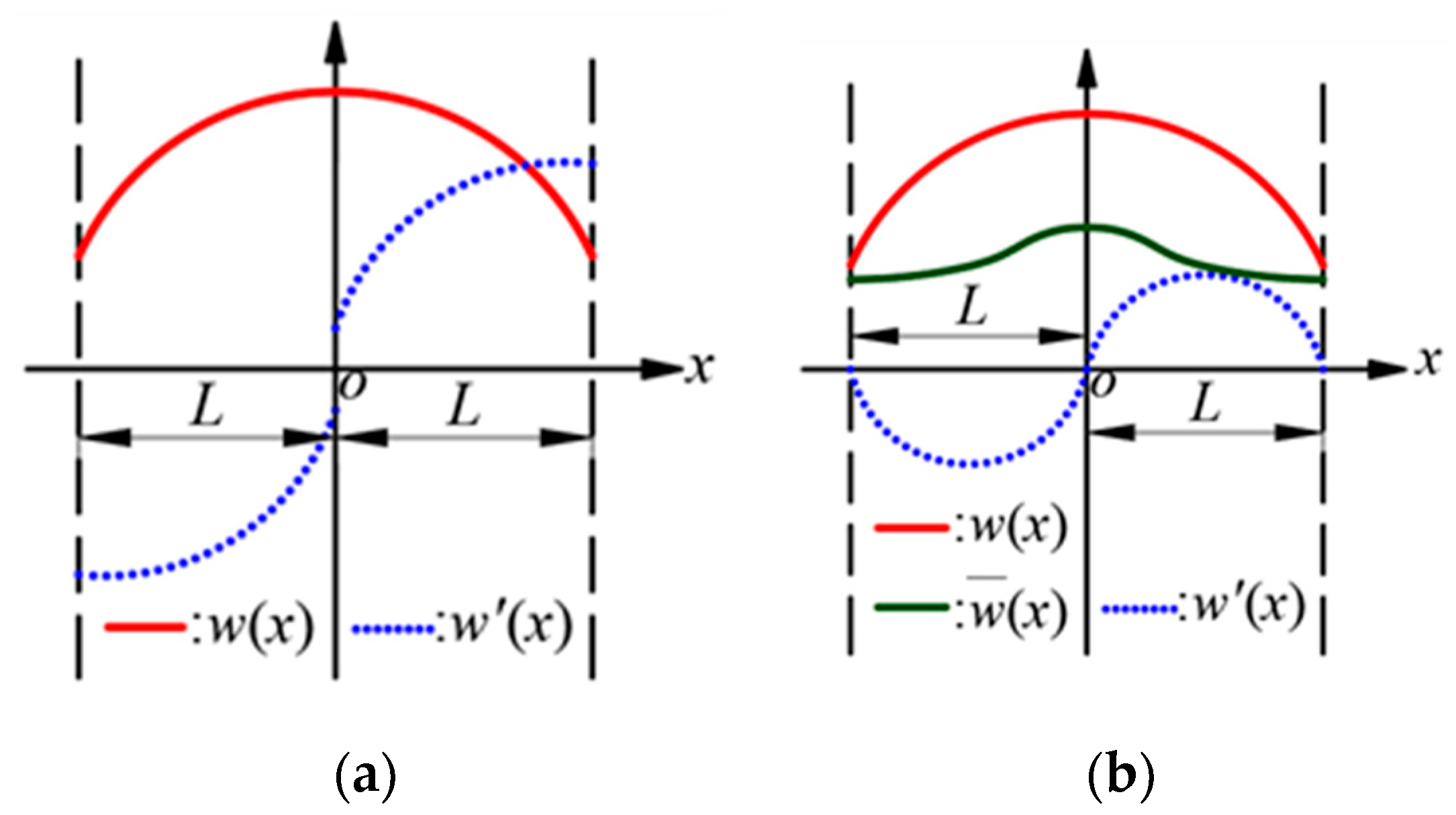
2.2. Admissible Displacement Functions

When the derivative of the displacement function represented by the traditional Fourier series is an odd function, discontinuities or jumps will occur at the end-point of the interval [−L, L], as shown in Figure 3a. The improved Fourier series method introduces auxiliary functions to the traditional Fourier series to avoid the phenomenon of discontinuities or jumps and to improve the poor convergence of the series [60].
The displacement functions of the composite stiffened plate can be expressed as
u 0 x , y , t = m = 2 n = 2 A m n ξ a m x ξ b n y
v 0 x , y , t = m = 2 n = 2 B m n ξ a m x ξ b n y
w 0 x , y , t = m = 2 n = 2 C m n ξ a m ( x ) ξ b n ( y )
φ x x , y , t = m = 2 n = 2 D m n ξ a m x ξ b n y
φ y x , y , t = m = 2 n = 2 E m n ξ a m x ξ b n y
where ξ a m ( x ) and ξ b n ( y ) are
ξ a m x = cos λ a m x , m 0 sin λ a m x , m < 0
ξ b n y = cos λ b n y , n 0 sin λ b n y , n < 0
where λ a m = m π / a and λ b n = n π / b . ξ a m ( x ) and ξ b n ( y ) (m, n = −2, −1) are the auxiliary functions, and the derivatives satisfy the following initial conditions at the boundaries.
ξ a m 0 = ξ a m a = ξ a m a = 0 , ξ a m 0 = 1
ξ b n 0 = ξ b n b = ξ b n b = 0 , ξ b n 0 = 1

2.3. Governing Equation and Solution

Utilizing the energy principle, the Lagrange energy functional L for the composite stiffened plate is
L = T p + T s U p U s V s p W
where Up and Us are the potential energy of the laminate panel and the laminate stiffener. Tp and Ts are the kinetic energy of the laminate panel and the laminate stiffener. Vsp is the elastic potential energy of the boundary spring. W is the work done by the external force.
The laminate panel potential energy Up and kinetic energy Tp are
U p = 1 2 0 a 0 b N x ε x x 0 + N y ε y y 0 + N x y ε x y 0 + M x χ x x + M y χ y y + M x y χ x y + Q x z γ x z + Q y z γ y z d x d y
T p = 1 2 U ˙ 2 + V ˙ 2 + W ˙ 2 d V
The laminate stiffener potential energy Us and kinetic energy Ts are
U s = 1 2 0 L S σ x ε x + τ x z γ x z d S d x
T s = 1 2 ρ 0 L S U ˙ s 2 + W ˙ s 2 d S d x
The boundary spring elastic potential energy Vsp is
V s p = 1 2 0 b h / 2 h / 2 k x 0 u u 0 2 + k x 0 v v 0 2 + k x 0 w w 0 2 + K x 0 x φ x 2 + K x 0 y φ y 2 x = 0 + k x a u u 0 2 + k x a v v 0 2 + k x a w w 0 2 + K x a x φ x 2 + K x a y φ y 2 x = a d y d z + 1 2 0 a h / 2 h / 2 k y 0 u u 0 2 + k y 0 v v 0 2 + k y 0 w w 0 2 + K y 0 x φ x 2 + K y 0 y φ y 2 y = 0 + k y b u u 0 2 + k y b v v 0 2 + k y b w w 0 2 + K y b x φ x 2 + K y b y φ y 2 y = b d x d z
W is the work done by the external force.
W = S f u u 0 + f v v 0 + f w w 0 + f φ x φ x + f φ y φ y d x d y
As per Rayleigh–Ritz method, the composite stiffened plate energy functional L is partialized by unknown Fourier coefficients G.
L G = 0 , G = A m n , B m n , C m n , D m n , E m n
The governing equation for the composite stiffened plate is
K ω 2 M G = F
where F = 0; setting m = M and n = N, Equation (41) transforms into a set of linear Equation (40) with 5 × (M + 1) × (N + 1) + 10 × (M + N + 2) unknown coefficients. The natural frequencies and mode shapes of the composite stiffened plate can be obtained by solving the eigenvalues and eigenvectors of Equation (41).
K ω 2 M G = 0

3. Numerical Results and Discussions

In this section, a numerical procedure is developed using MATLAB 2020 based on the theoretical model in the previous section. Several numerical examples are conducted to demonstrate that the method in this paper exhibits good convergence, accuracy, and reliability. Initially, the convergence of the method is investigated, and a suitable spring stiffness value is selected. Subsequently, the accuracy of the method is verified through comparisons with the FEM results and experimental data from the published literature. Finally, the impact of various design parameters on the vibration characteristics of the composite stiffened plate is discussed.

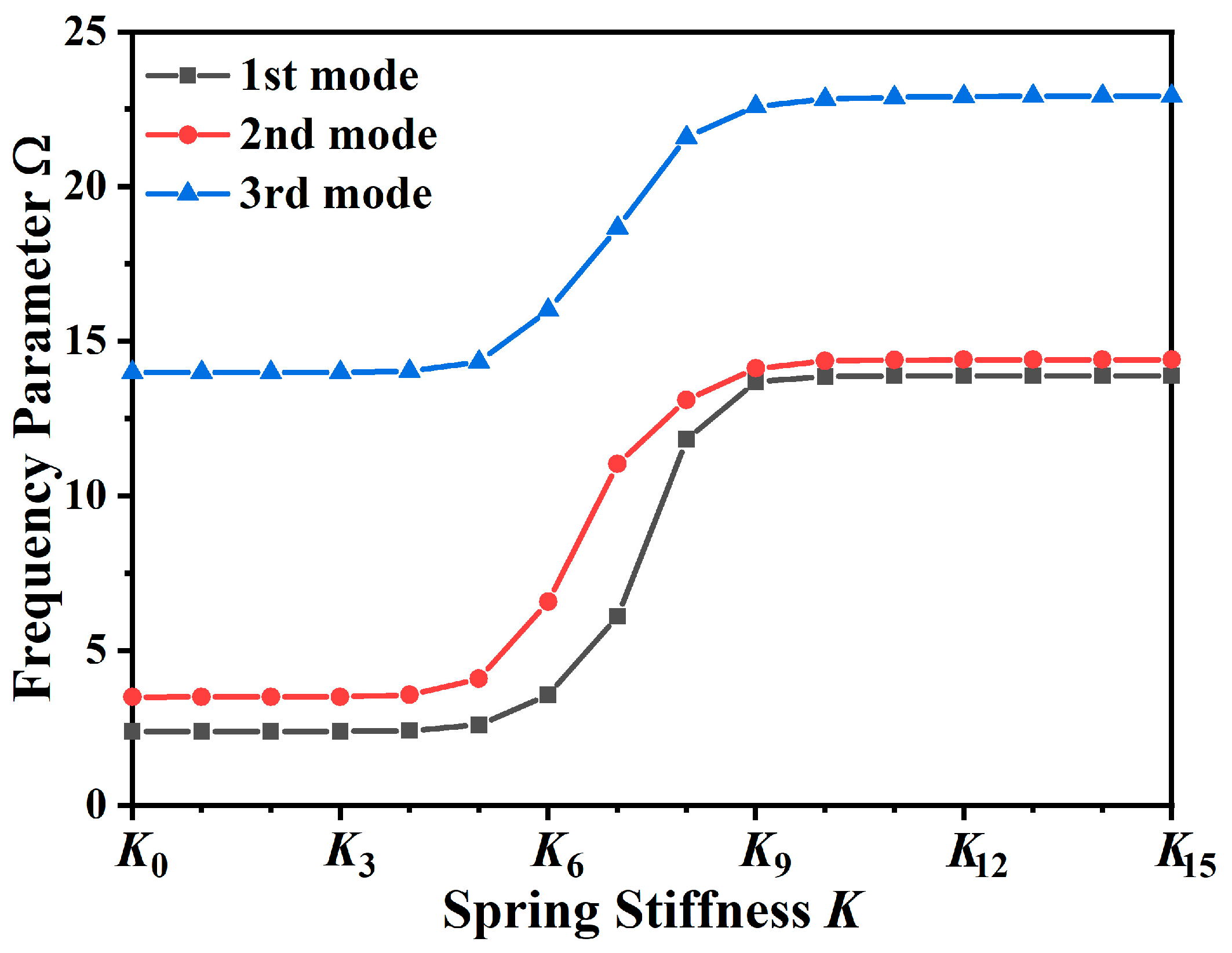
3.1. Convergency Analysis

This section investigates the convergence of the numerical procedure developed in this paper. The laminate panel dimensions are a/b = 1 and hp/b = 0.01, and the laminate stiffener are hs/hp = 1 and bs/b = 0.01. The longitudinal laminate stiffener, aligned parallel to the y-axis, is positioned at x = a/2. The material parameters are E2 = 10 GPa, E1 = 20 E2, G12 = 0.5 E2, G13 = 0.5 E2, G23 = 0.33 E2, μ12 = 0.25, and ρ = 1500 kg/m3. The ply schemes of the laminate panel and laminate stiffener are [0/90] and [0]10, respectively. Table 1 presents the first eight dimensionless frequency parameters of the composite stiffened plate under fully free boundary conditions. The composite stiffened plate dimensionless frequency parameter is Ω = ω b 2 / h p ρ / E 2 . Table 1 reveals that the frequency parameters gradually converge as the mode truncation number increases, indicating that the method exhibits good convergence and accuracy. Considering both computational efficiency and accuracy, the mode truncation number for subsequent numerical calculations is M = N = 16.
In this paper, artificial virtual spring stiffness is adjusted to simulate the composite stiffened plate boundary conditions. For the free boundary condition, the spring stiffness value is set to 0. For the clamped boundary condition, the spring stiffness value is ideally set to , but it cannot be achieved in numerical calculations. Therefore, it is necessary to select suitable values for the spring stiffness K (ku, kv, kw, Kx, and Ky) to simulate the clamped boundary condition.
Figure 4 illustrates the first three dimensionless frequency parameters of the composite stiffened plate for varying spring stiffness K. The geometrical and material parameters of the composite stiffened plate depicted in Figure 4 are consistent with Table 1. The boundary conditions of the composite stiffened plate are FCFE, i.e., x = 0 and x = a are the free boundaries (F), y = 0 is the clamped support boundary (C), and y = b is the elastic support boundary (E). The spring stiffness varies from K0 (0) to K15 (1015). According to Figure 4, when the spring stiffness value is below K5, the frequency parameter is minimally influenced by the spring stiffness. As the spring stiffness value increases from K5 to K10, the frequency parameter rises rapidly, indicating strengthened boundary constraints. Within this range, the boundary condition is considered as elastic support. Above K10, the frequency parameter remains essentially unchanged, which can be regarded as clamped support. In this study, the spring stiffness is set to K13 to simulate the clamped support. Table 2 lists the spring stiffness values K for classic boundary conditions at x = 0.

3.2. Method Verification

In this section, the theoretical results are compared with the FEM results and the experimental results published in the literature to verify the accuracy of the proposed method.

3.2.1. Composite Stiffened Plate Vibration Characteristics Verification

Rikards [27] explored the free vibration of the composite stiffened plate with a central stiffener under fully clamped boundary conditions. The dimensions are a = 0.25 m, b = 0.5 m, hp = 0.00104 m, hs = 0.0105 m, and bs = 0.00364 m. The central stiffener, positioned at x = 1/2 a, is parallel to the y-axis. The material parameters are E1 = 128 GPa, E2 = 11 GPa, G12 = 4.48 GPa, G13 = 4.48 GPa, G23 = 1.53 GPa, μ12 = 0.25, and ρ = 1500 kg/m3. The ply schemes for the laminate panel and laminate stiffener are [0/ ± 45/90]s and [07/907]s, respectively. Each ply thickness is 0.13 mm. The FEM model of the composite stiffened plate is established using Patran. For the finite element analysis (FEA) of the composite stiffened plate, the upper frequency limit is set at 1000 Hz. Based on the bending wavelength formulation, the maximum element size should not exceed 0.02 m. Both the laminate panel and the laminate stiffener are modeled using shell elements, with a maximum element size of 0.0125 m, and the number of total meshes is 840. Nastran is used to analyze the composite stiffened plate free and forced vibration characteristics. Table 3 presents the first five natural frequencies of the composite stiffened plate. The average difference between the theoretical results and the FEM results is 2.15% and the maximum error does not exceed 5%. Figure 5 shows the composite stiffened plate vibration displacement response subjected to single-point excitation. The excitation position is (a/2, b/2) and the excitation amplitude is 1 N. It can be found that the theoretical results and the FEM results of displacement response are in good agreement.

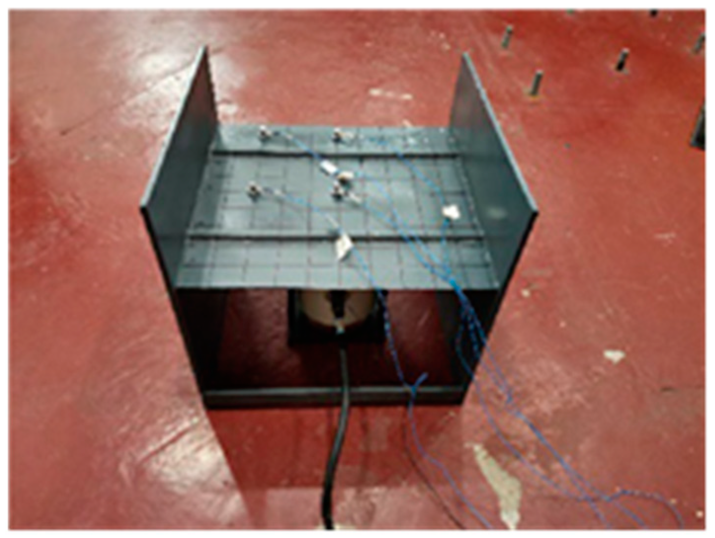
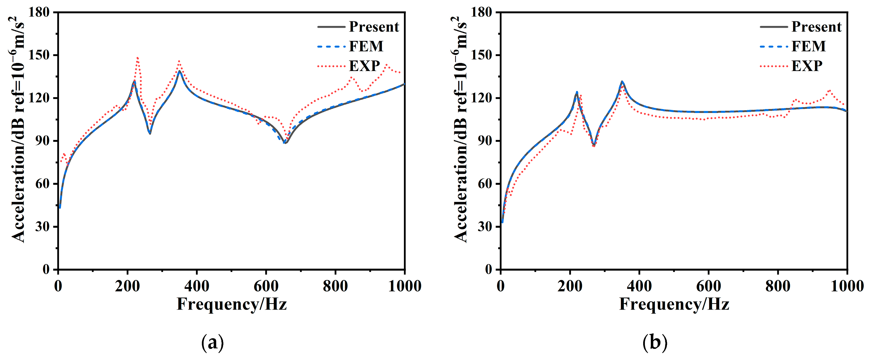
3.2.2. Steel Stiffened Plate Vibration Characteristics Verification

GAO [25] conducted an experimental study on the steel stiffened plate free and forced vibration. The dimensions of the steel stiffened plate are a = 0.5 m, b = 0.5 m, hp = 0.008 m, hs = 0.01 m, and bs = 0.01 m. The stiffeners are arranged at x = 1/4 a and x = 3/4 a, parallel to the y-axis. The material parameters are E = 210 GPa, μ = 0.3, and ρ = 7800 kg/m3. The boundary condition is FCFC, i.e., x = 0 and x = a are the free boundaries, and y = 0 and y = b are the clamped support boundaries. Patran is used to create the FEM model for the steel stiffened plate. The calculation upper frequency is 1000 Hz. According to the bending wavelength formulation, the maximum element size must not exceed 0.046 m. The panel and stiffeners are modeled using shell elements and beam elements, respectively, with a maximum element size of 0.0125 m. The total number of shell elements is 1600, and there are 80 beam elements. Nastran is employed to analyze the steel stiffened plate vibration characteristics. GAO [25] performed a modal experiment using the multi-point excitation and single-point pickup techniques. Both sides of the steel stiffened plate are fixed to simulate the clamped boundary conditions. An acceleration sensor is arranged at the center of the steel stiffened plate. A force hammer is used to knock the excitation points one by one, and the natural frequencies and the mode shapes are obtained through frequency analysis. Furthermore, GAO also conducted a forced vibration experiment of the steel stiffened plate under single-point excitation. A vibration exciter, which induces a linear sweep excitation at an amplitude of 1 N, is positioned beneath the center of the stiffened plate and is connected to the stiffened plate through a force sensor. The force sensor is used to record the excitation information from the vibration exciter. Acceleration sensors, arranged at the excitation point (a/2, b/2) and the observation point (a/2, b/5), are used to measure the vibration acceleration response through the data acquisition system post-processing. Figure 6 shows the experiment arrangements of the vibration exciter and sensors on the steel stiffened plate. Table 4 displays the first three modes of the theoretical, FEM, and experimental results and shows that the mode shapes are consistent. The maximum discrepancy between the theoretical and experimental results is less than 5%. Figure 7 illustrates the steel stiffened plate vibration acceleration levels of the excitation and observation points. From Figure 7, it is obvious that the theoretical curves are in good agreement with the FEM curves. Both theoretical and experimental curves show similar trends, with relatively minor deviations at single peaks. It demonstrates that the theoretical method presented in this paper effectively analyzes the stiffened plate free and forced vibration.

3.3. Parameter Analysis

The previous section demonstrated that the theoretical method presented in this paper has good reliability and accuracy in studying the composite stiffened plate vibration characteristics. This section explores the impact of the geometric, material, and laminate ply parameters on the free and forced vibration characteristics of the composite stiffened plate. In this section, a composite stiffened plate with two stiffeners is taken as the research object. The stiffeners are located at x = 1/4 a and x = 3/4 a, parallel to the y-axis. Unless specially stated, the laminate material parameters are E2 = 10 GPa, E1 = 20 E2, G12 = 0.6 E2, G13 = 0.6 E2, G23 = 0.5 E2, μ12 = 0.25, and ρ = 1600 kg/m3, while the isotropic parameters are E = 210 GPa, μ = 0.3, and ρ = 7850 kg/m3. The boundary conditions are simply supported.

3.3.1. Free Vibration of Composite Stiffened Plate

Table 5 presents the first eight dimensionless frequency parameters of the composite stiffened plate with various geometric parameters. The laminate panel aspect ratio a/b is 1, 1.5, and 2, and the laminate panel thickness–length ratio hp/b is 0.004, 0.006, 0.008, and 0.01. The stiffener dimension is hs = 0.01 b and bs = 0.01 b. The ply schemes of the laminate panel and stiffeners are [0/90] and [0]10, respectively. According to Table 5, it is evident that the composite stiffened plate frequency parameter decreases as the aspect ratio and panel thickness increase.
Table 6 presents the dimensionless frequency parameters of the composite stiffened plate with different anisotropic ratios. The dimensions are a/b = 1, 1.5, 2, hp = 0.01 b, hs = 0.01 b, and bs = 0.01 b. The laminate panel material anisotropic ratios are 5, 10, 20, and 30. The laminate panel ply scheme is [45/−45]s, while the stiffener material is made from isotropic material. As indicated in Table 6, both the stiffness and frequency parameters of the composite stiffened plate increase as the anisotropic ratio increases.
During designing the laminated composite structure, the ply scheme, ply angle, and ply number are the key design parameters. Reasonable ply design solutions can meet the special functional requirements of the actual project. Figure 8 illustrates the variation curves of the fundamental frequency parameters of the composite stiffened plates with different ply angles, which vary from 0° to 180° in 5° increments. The dimensions are a/b = 1, 1.5, 2, hp/b = 0.01, hs = 0.01 b, and bs = 0.01 b. The ply schemes of the laminate panel are [θ]4, [0/θ]2, [0/θ]s, and [θ/0]s. The ply scheme of the laminate stiffener is [0]10. According to Figure 8, the fundamental frequency parameter is symmetrical with respect to 90° across different geometries and ply schemes. The subsequent study on the ply angle can be discussed in the range of 0° to 90°. For the square composite stiffened plates, the fundamental frequency parameter initially increases and then decreases with the change in the ply angle. For the rectangular composite stiffened panels, the fundamental frequency parameter increases gradually. As the plate thickness increases, the trend of the fundamental frequency parameter with the changing ply angle remains consistent, although the value of the frequency parameter decreases. Figure 9 explores the impact of the ply number on the composite stiffened plate frequency parameter. The ply schemes are [0/90]n, [30/−30]n, [45/−45]n, and [75/−75]n. The thickness and material of each layer is the same. The results from Figure 9 indicate that the frequency parameter increases as the ply numbers increase. However, once the ply number reaches a certain level, the frequency parameter tends to stabilize and remain essentially unchanged.
Stiffener structural parameters are crucial for the design of stiffened plate vibrations. Figure 10 shows the natural frequency variation in the composite stiffened plate with different stiffener heights. The dimensions are b = 0.5 m, a = 2 b, hp = 0.01 b, bs = 0.01 b, and hs/hp = 2, 4, 6, 8, 10. The ply schemes of the laminate panel and laminate stiffener are [0/90]10 and [0]10. According to Figure 10, the natural frequency of the composite stiffened plate increases as the stiffener height increases. Figure 11 investigates the influences of stiffener space on the natural frequency of the composite stiffened plate. The dimensions are b = 0.5 m, a = 2b, hp = 0.01 b, hs = 2 hp, and bs = 0.01 b. The stiffener space c is 0.3 m, 0.4 m, 0.5 m, and 0.6 m. As depicted in Figure 11, the fundamental frequency of the composite stiffened plate decreases as the stiffener space increases. Figure 12 explores the impact of the stiffener numbers on the composite stiffened plate natural frequency. The number of stiffeners is 2, 4, 6, and 8. The results, as shown in Figure 12, indicate that the frequency parameter increases with the stiffener numbers.

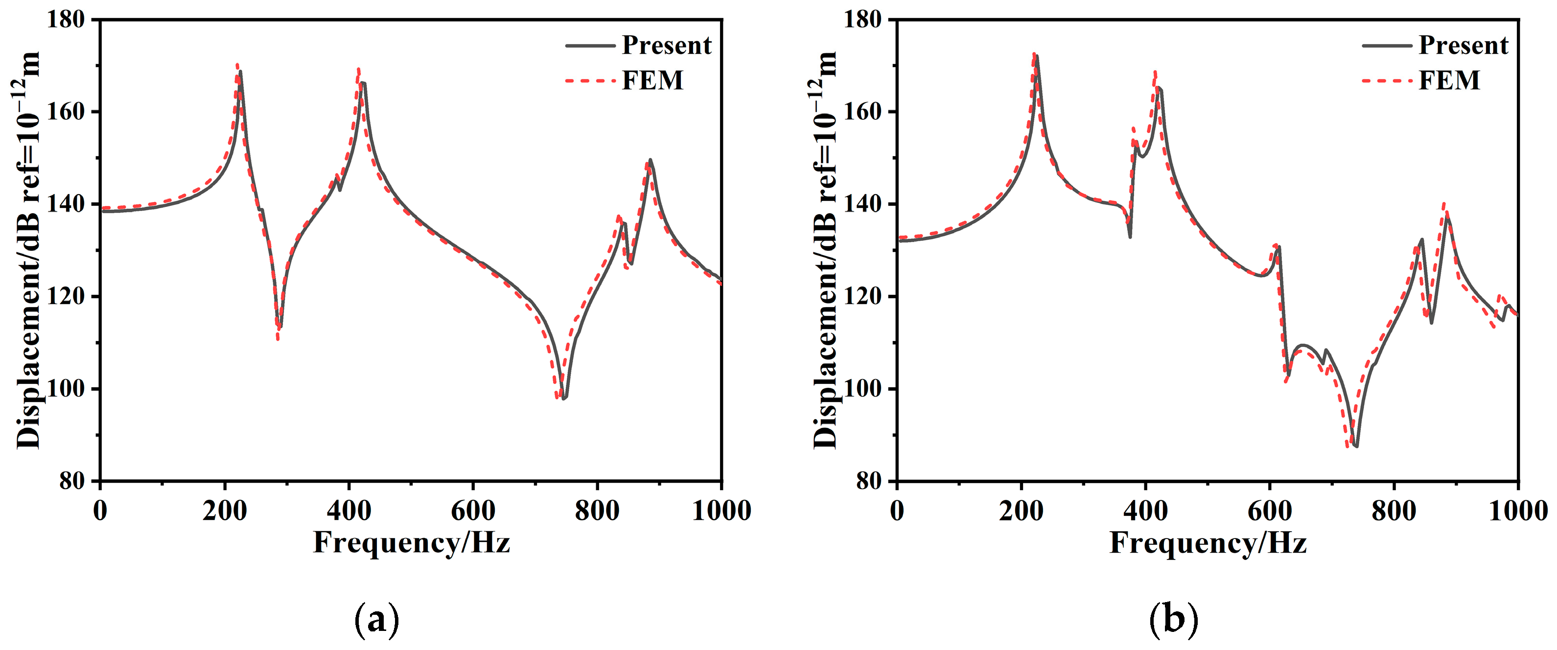
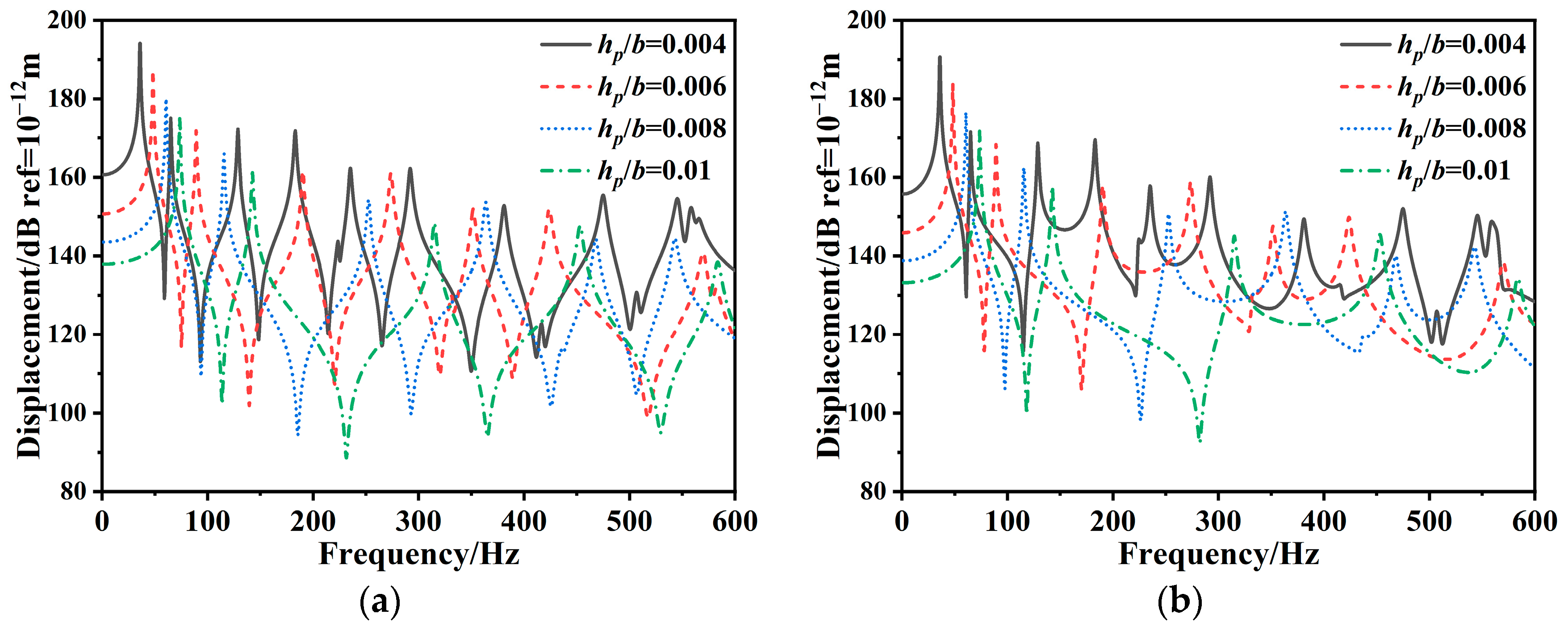
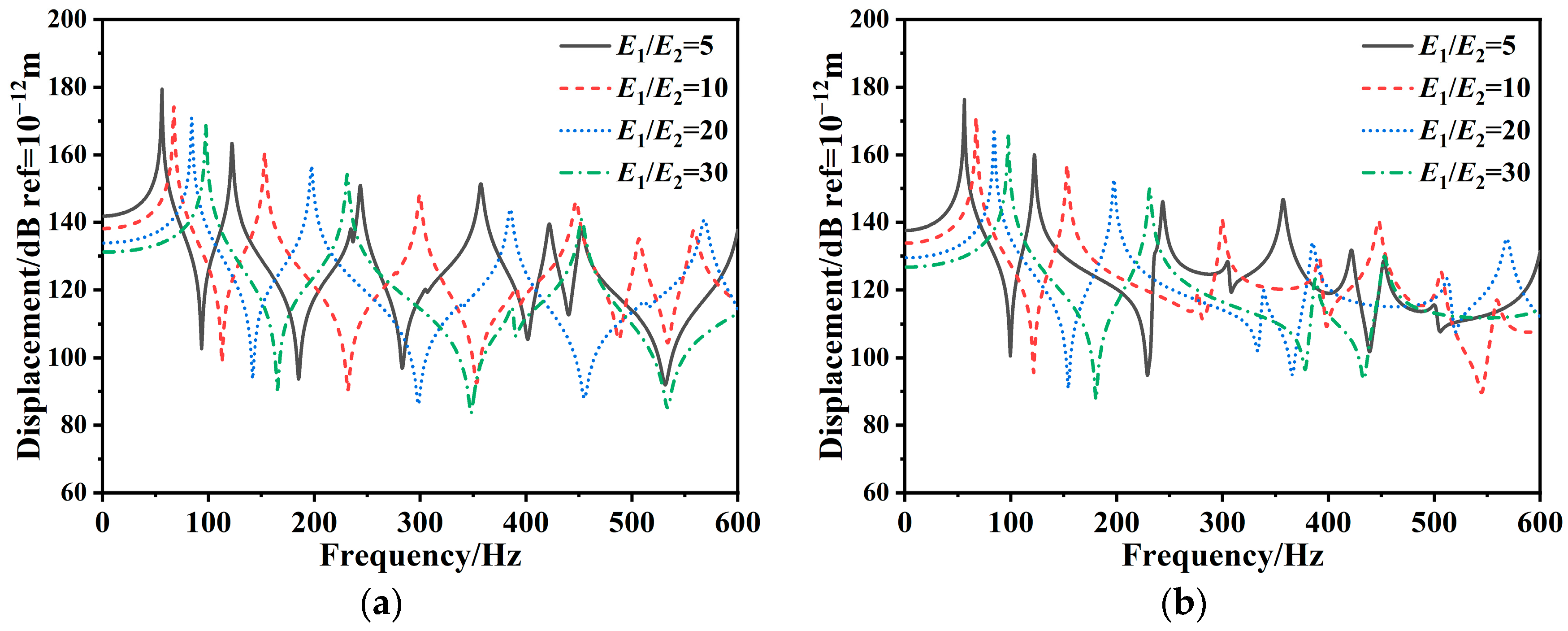
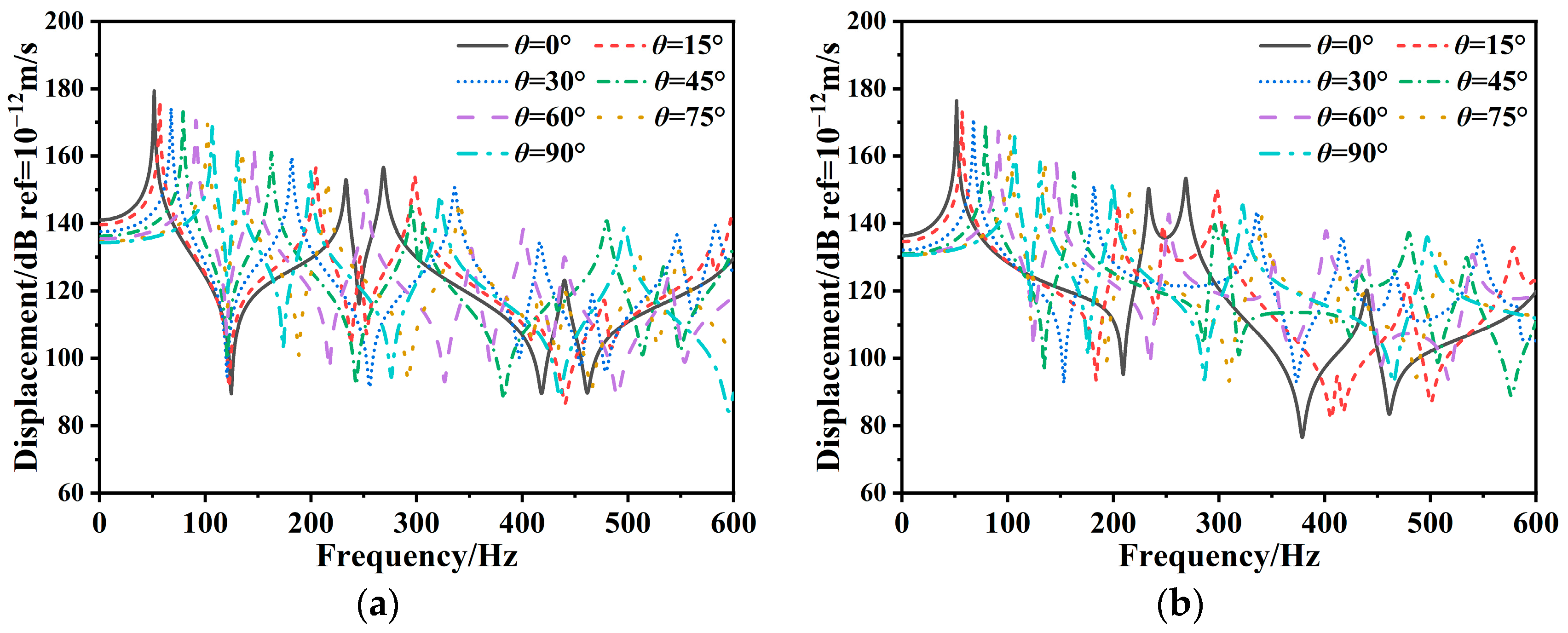
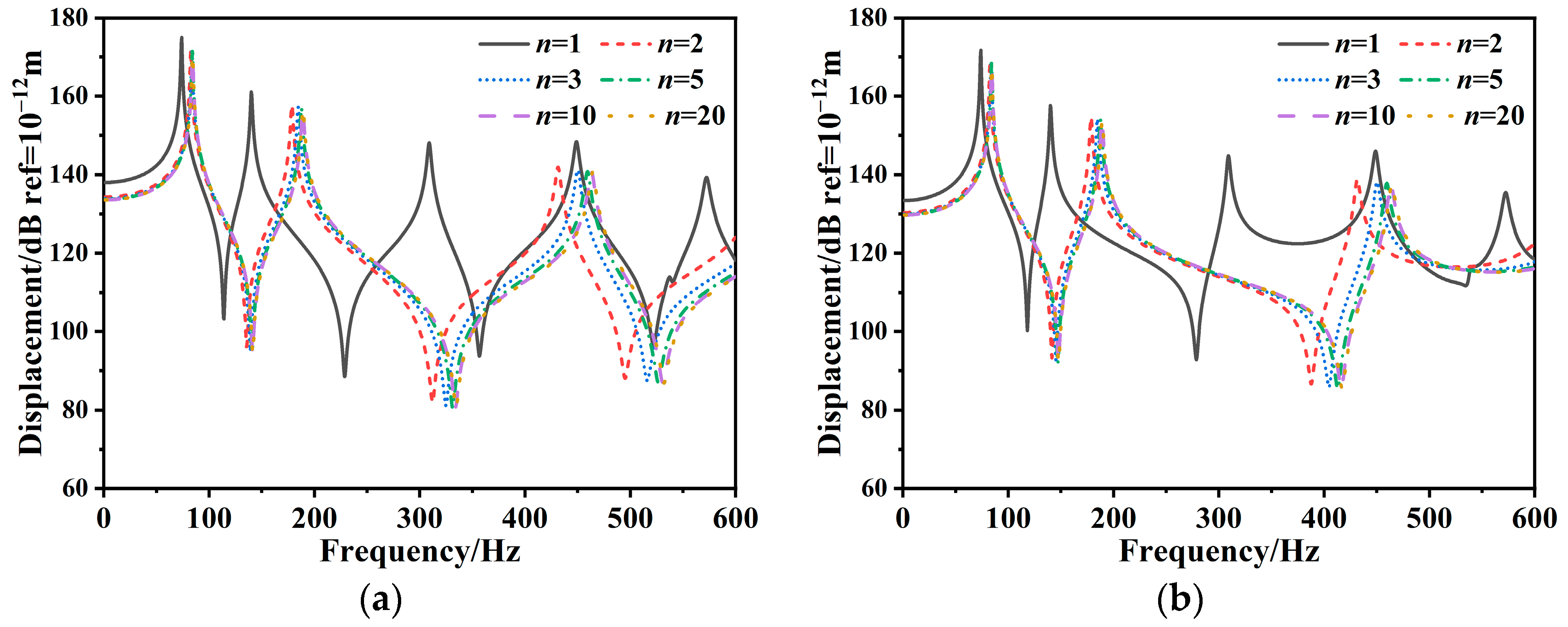
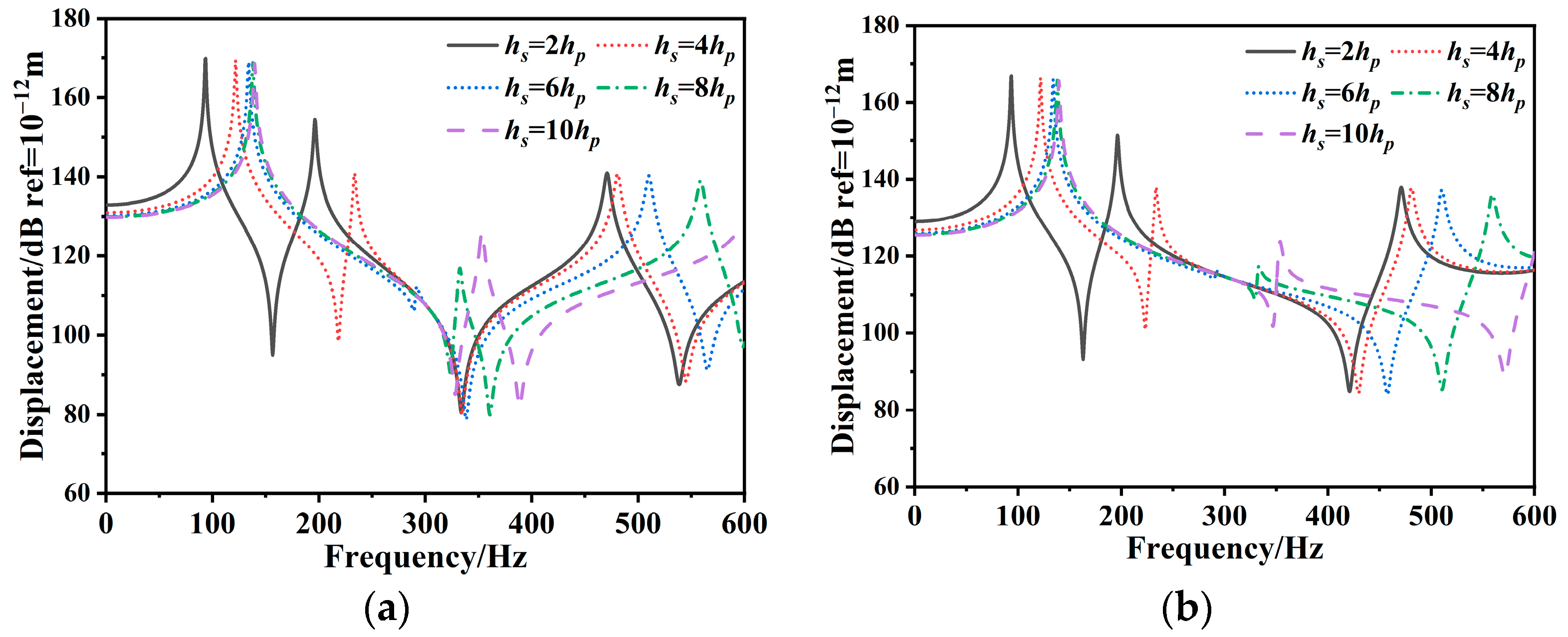
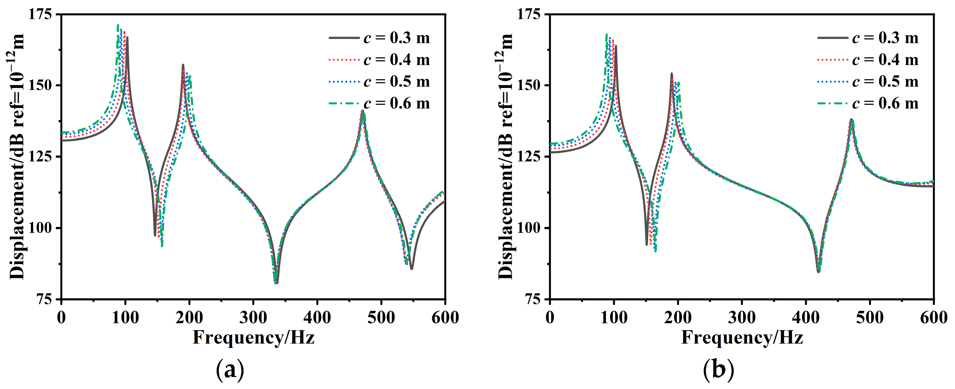
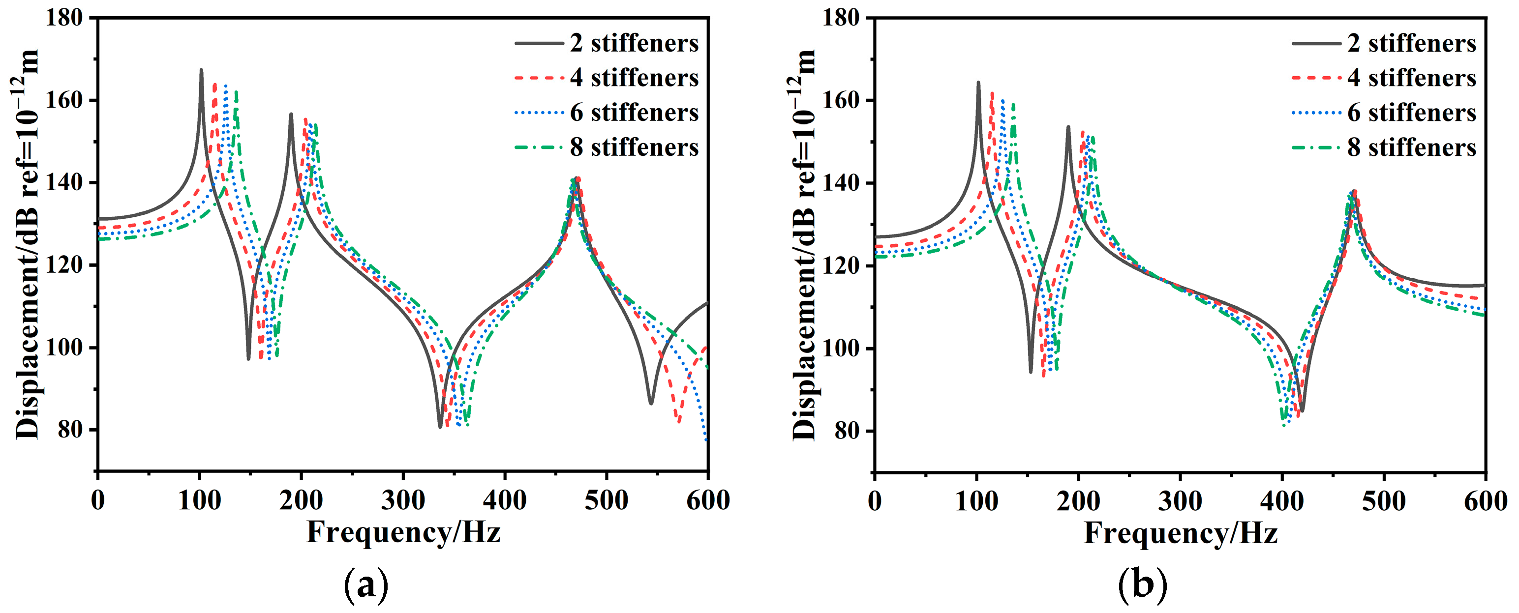
3.3.2. Forced Vibration of Composite Stiffened Plate

This section studies the vibration displacement response of the composite stiffened plate under single-point excitation, utilizing the theoretical method presented in this paper. The excitation position is (a/2, b/2) and the excitation amplitude is 1 N.
Figure 13 displays the displacement response curves of the composite stiffened plate with varying thicknesses. The dimensions are b = 0.5 m, a = 2 b, hp/b = 0.004, 0.006, 0.008, 0.01, hs = 0.01 b, and bs = 0.01 b. The laminate ply schemes are consistent with Table 5. According to Figure 13, as the laminate panel thickness increases, the displacement response curve shifts to the higher frequency region, and the resonant peak value decreases. As the laminate panel thickness increases, the natural frequency and stiffness of the composite stiffened plate also increase.
Figure 14 illustrates the displacement response of the composite stiffened plate with different anisotropic ratios. The dimensions are b = 0.5 m, a = 2 b, hp = 0.01 b, hs = 0.01 b, and bs = 0.01 b. The material and ply scheme parameters are consistent with Table 6. According to Figure 14, as the anisotropic ratio increases, the resonance peak of the displacement response shifts to a higher frequency, and its amplitude decreases. It is attributed to the improved structural stiffness of the composite stiffened plate, which leads to an increase in the natural frequency.
Figure 15 investigates the influence of ply angle on the displacement response of the composite stiffened plate. The dimensions are b = 0.5 m, a = 2 b, hp = 0.01 b, hs = 0.01 b, and bs = 0.01 b. The ply scheme for the laminate panel is [θ]4, with the ply angles varying from 0° to 90° in 15° increments. According to Figure 15, as the ply angle increases, the first-order resonance frequency shifts to a higher frequency region and the corresponding amplitude decreases. The increase in the ply angle significantly affects the higher-order modes, and there is uncertainty in the displacement response curve of the composite stiffened plate. Figure 16 presents the effect of the ply number on the vibration displacement response of the composite stiffened plate. The ply schemes are [0/90], [0/90]2, [0/90]3, [0/90]5, [0/90]10, and [0/90]20. As illustrated in Figure 16, the displacement response curve shifts to a higher frequency region as the ply number increases. However, as the ply number increases to a certain level, the displacement response curves gradually converge and coincide.
Figure 17 illustrates the influence of the stiffener height on the displacement response of the composite stiffened plate. As the stiffener height increases, the displacement response curve shifts toward the higher frequency region. However, increasing the stiffener height does not uniformly reduce the structural vibration displacement response across all frequencies. This is because the higher stiffener increases the overall stiffness of the structure while changing the local mass distribution. Figure 18 shows the vibration displacement response of the composite stiffened plate with different stiffener spaces. It shows that as the stiffener space increases, the first resonance peak moves to a lower frequency region, while the first resonance peak value increases. The stiffener space leads to a change in the local stiffness and mass distribution, which has a complex influence on the composite stiffened plate vibration, with different performances at different frequency regions. Figure 19 analyzes the impact of varying stiffener numbers on the displacement response of the composite stiffened plate. As the number of stiffeners increases, the displacement response of the composite stiffened plate decreases, and the resonance peak shifts to a higher frequency region.

4. Conclusions

In this paper, a unified theoretical model for the composite stiffened plate is established utilizing the FSDT and Timoshenko beam theory. According to the energy principle and Rayleigh–Ritz method, the governing equation of the composite stiffened plate is derived and solved. The displacement functions are constructed using the improved Fourier series, which offers advantages in addressing boundary condition issues. The theoretical model is applied to explore the impact of various parameters including geometric dimensions, material properties, laminate ply design, and stiffener characteristics on the vibration behavior of the composite stiffened plate. The conclusions are as follows:
  • The theoretical model developed in this paper is suitable for studying the free and forced vibration characteristics of isotropic and composite stiffened plates with good convergence efficiency and calculation accuracy.
  • Increasing both the thickness and material stiffness of the laminate panel enhances the overall stiffness and natural frequency of the composite stiffened plate, subsequently reducing the vibration response.
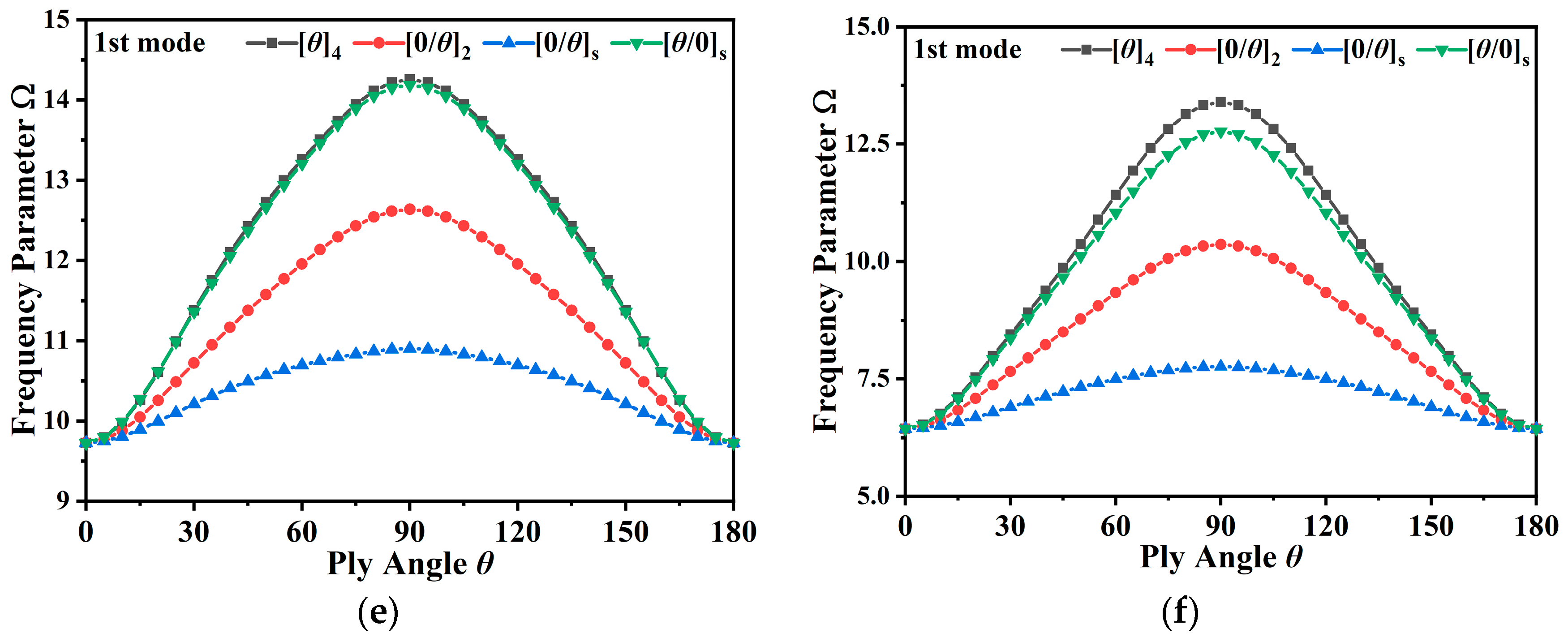
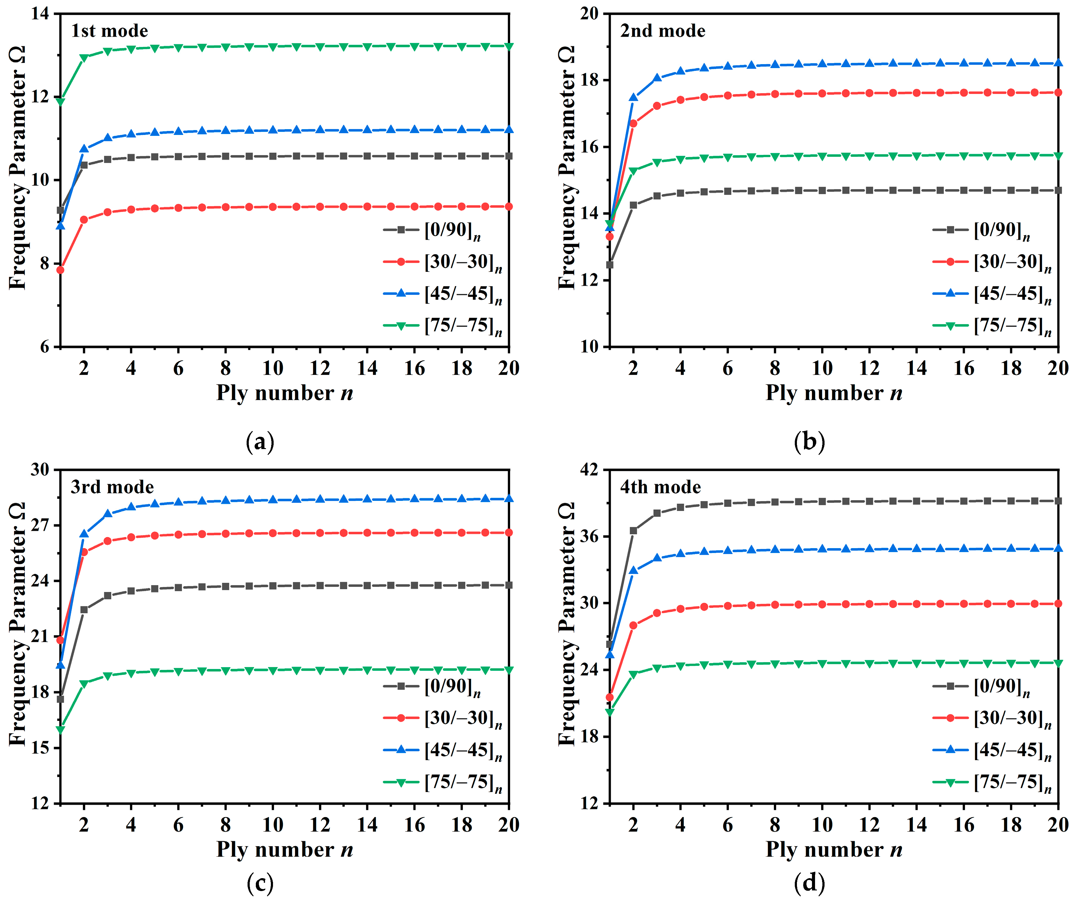
  • In designing the laminate ply scheme, increasing the ply angle can reduce the first-order resonance peak and enhance the low-order vibration response of a rectangular composite stiffened plate. Additionally, the vibration response of the composite stiffened plate can be minimized by increasing the ply number. However, as the ply number increases to a certain level, the vibration behavior of the composite stiffened plate remains unchanged.
  • The natural frequency of the composite stiffened plate increases, and the vibration response peak shifts to a higher frequency region as the stiffener height increases. Conversely, with an increase in the stiffener space, the fundamental frequency of the composite stiffened plate decreases, while the amplitude of the first-order resonance peak increases. Additionally, as the number of stiffeners increases, the composite stiffened plate natural frequency increases, and the vibration response decreases.
In summary, the theoretical method presented in this paper demonstrates broad applicability and effectively predicts the free and forced vibration of composite stiffened plates. The parametric analysis confirms that optimal structural design can significantly mitigate vibration issues of composite stiffened plates. This study provides theoretical guidance for the low-vibration design and application of composite stiffened plates in ships.

Author Contributions

Conceptualization, X.G., X.W. and W.W.; methodology, X.G. and X.W.; software, X.G., J.S. and Y.F.; validation, X.G. and J.S.; formal analysis, X.G., X.W. and W.W.; investigation, X.G.; resources, W.W.; data curation X.G.; writing—original draft preparation, X.G.; writing—review and editing, X.G., X.W., W.W. and Y.L.; visualization, X.G.; supervision, X.W. and W.W.; project administration, X.W. and W.W.; funding acquisition, X.W. and W.W. All authors have read and agreed to the published version of the manuscript.

Funding

This work is financially supported by the National Natural Science Foundation of China (No. 51779201), Special Project for High-Tech Ships of China (CBG4N21-1-4), and National Key Re-search and Development Program of China (2023YFC2811900).

Institutional Review Board Statement

No applicable.

Informed Consent Statement

No applicable.

Data Availability Statement

Data is available upon request from the authors.

Acknowledgments

The authors thank the parents, teachers, and friends who support and care about their scientific research work.

Conflicts of Interest

The authors declare no conflicts of interest.

References

  1. Hertzberg, T. LASS, Lightweight Construction Applications at Sea; SP Technical Research Institute of Sweden: Växjö, Sweden, 2009. [Google Scholar]
  2. Evegren, F.; Hertzberg, T.; Rahm, M. LASS-C, Lightweight Construction of a Cruise Vessel; SP Technical Research Institute of Sweden: Växjö, Sweden, 2011; p. 44. [Google Scholar]
  3. Aksu, G.; Ali, R. Free Vibration Analysis of Stiffened Plates Using Finite Difference Method. J. Sound Vib. 1976, 48, 15–25. [Google Scholar] [CrossRef]
  4. Chen, C.J.; Liu, W.; Chern, S.M. Vibration Analysis of Stiffened Plates. Comput. Struct. 1994, 50, 471–480. [Google Scholar] [CrossRef]
  5. Lee, D.-M.; Lee, I. Vibration Analysis of Anisotropic Plates with Eccentric Stiffeners. Comput. Struct. 1995, 57, 99–105. [Google Scholar] [CrossRef]
  6. Liew, K.M.; Xiang, Y.; Kitipornchai, S.; Lim, M.K. Vibration of Rectangular Mindlin Plates with Intermediate Stiffeners. J. Vib. Acoust. 1994, 116, 529–535. [Google Scholar] [CrossRef]
  7. Peng, L.X.; Liew, K.M.; Kitipornchai, S. Buckling and Free Vibration Analyses of Stiffened Plates Using the FSDT Mesh-Free Method. J. Sound Vib. 2006, 289, 421–449. [Google Scholar] [CrossRef]
  8. Cho, D.S.; Vladimir, N.; Choi, T.M. Simplified Procedure for The Free Vibration Analysis of Rectangular Plate Structures with Holes and Stiffeners. Pol. Marit. Res. 2015, 22, 71–78. [Google Scholar] [CrossRef]
  9. Cho, D.; Vladimir, N.; Choi, T. Natural Vibration Analysis of Stiffened Panels with Arbitrary Edge Constraints Using the Assumed Mode Method. Proc. Inst. Mech. Eng. Part M J. Eng. Marit. Environ. 2015, 229, 340–349. [Google Scholar] [CrossRef]
  10. Cho, D.S.; Kim, B.H.; Kim, J.-H.; Choi, T.M.; Vladimir, N. Free Vibration Analysis of Stiffened Panels with Lumped Mass and Stiffness Attachments. Ocean Eng. 2016, 124, 84–93. [Google Scholar] [CrossRef]
  11. Cho, D.S.; Kim, J.-H.; Choi, T.M.; Kim, B.H.; Vladimir, N. Free and Forced Vibration Analysis of Arbitrarily Supported Rectangular Plate Systems with Attachments and Openings. Eng. Struct. 2018, 171, 1036–1046. [Google Scholar] [CrossRef]
  12. Cho, D.S.; Kim, B.H.; Kim, J.-H.; Vladimir, N.; Choi, T.M. Forced Vibration Analysis of Arbitrarily Constrained Rectangular Plates and Stiffened Panels Using the Assumed Mode Method. Thin-Walled Struct. 2015, 90, 182–190. [Google Scholar] [CrossRef]
  13. Qin, X.C.; Dong, C.Y.; Wang, F.; Qu, X.Y. Static and Dynamic Analyses of Isogeometric Curvilinearly Stiffened Plates. Appl. Math. Model. 2017, 45, 336–364. [Google Scholar] [CrossRef]
  14. Zhang, K.; Lin, T.R. An Analytical Study of Vibration Response of a Beam Stiffened Mindlin Plate. Appl. Acoust. 2019, 155, 32–43. [Google Scholar] [CrossRef]
  15. Sahoo, P.R. Free Vibration Analysis of Stiffened Plates. J. Vib. Eng. Technol. 2020, 8, 869–882. [Google Scholar] [CrossRef]
  16. Sahoo, P.R.; Barik, M. A Numerical Investigation on the Dynamic Response of Stiffened Plated Structures under Moving Loads. Structures 2020, 28, 1675–1686. [Google Scholar] [CrossRef]
  17. Liu, X.; Li, Y.; Lin, Y.; Banerjee, J.R. Spectral Dynamic Stiffness Theory for Free Vibration Analysis of Plate Structures Stiffened by Beams with Arbitrary Cross-Sections. Thin-Walled Struct. 2021, 160, 107391. [Google Scholar] [CrossRef]
  18. Qin, X.; Shen, Y.; Chen, W.; Yang, J.; Peng, L.X. Bending and Free Vibration Analyses of Circular Stiffened Plates Using the FSDT Mesh-Free Method. Int. J. Mech. Sci. 2021, 202–203, 106498. [Google Scholar] [CrossRef]
  19. Zhang, K.; Pan, J.; Lin, T.R. Vibration of Rectangular Plates Stiffened by Orthogonal Beams. J. Sound Vib. 2021, 513, 116424. [Google Scholar] [CrossRef]
  20. Liu, Z.; Niu, J.; Jia, R. Dynamic Analysis of Arbitrarily Restrained Stiffened Plate under Moving Loads. Int. J. Mech. Sci. 2021, 200, 106414. [Google Scholar] [CrossRef]
  21. Ko, D.-H.; Boo, S.-H. Efficient Structural Dynamic Analysis Using Condensed Finite Element Matrices and Its Application to a Stiffened Plate. J. Mar. Sci. Eng. 2022, 10, 1958. [Google Scholar] [CrossRef]
  22. Guo, C.; Liu, T.; Wang, Q.; Qin, B.; Wang, A.; Shi, X. Free Vibration Characteristics of Concentric Stiffened Rectangular Plates Determined Based on Spectral Tchebyshev Technique. Appl. Acoust. 2022, 191, 108670. [Google Scholar] [CrossRef]
  23. Shen, Y.; He, X.; Chen, W.; Liang, N.; Peng, L.X. Meshless Simulation and Experimental Study on Forced Vibration of Rectangular Stiffened Plate. J. Sound Vib. 2022, 518, 116602. [Google Scholar] [CrossRef]
  24. Wang, Y.; Fan, J.; Shen, X.; Liu, X.; Zhang, J.; Ren, N. Free Vibration Analysis of Stiffened Rectangular Plate with Cutouts Using Nitsche Based IGA Method. Thin-Walled Struct. 2022, 181, 109975. [Google Scholar] [CrossRef]
  25. Gao, C.; Pang, F.; Li, H.; Jia, D. A Semi-Analytical Method for the Dynamic Characteristics of Stiffened Plate with General Boundary Conditions. Thin-Walled Struct. 2022, 178, 109513. [Google Scholar] [CrossRef]
  26. Chen, Z.; Jia, X.; Lin, Y.; Liu, H.; Wu, W. Experimental Investigation on Vibro-Acoustic Characteristics of Stiffened Plate Structures with Different Welding Parameters. J. Mar. Sci. Eng. 2022, 10, 1832. [Google Scholar] [CrossRef]
  27. Rikards, R.; Chate, A.; Ozolinsh, O. Analysis for Buckling and Vibrations of Composite Stiffened Shells and Plates. Compos. Struct. 2001, 51, 361–370. [Google Scholar] [CrossRef]
  28. Ahmadian, M.T.; Zangeneh, M.S. Application of Super Elements to Free Vibration Analysis of Laminated Stiffened Plates. J. Sound Vib. 2003, 259, 1243–1252. [Google Scholar] [CrossRef]
  29. Qing, G.; Qiu, J.; Liu, Y. Free Vibration Analysis of Stiffened Laminated Plates. Int. J. Solids Struct. 2006, 43, 1357–1371. [Google Scholar] [CrossRef]
  30. Nayak, A.N.; Bandyopadhyay, J.N. Free Vibration Analysis of Laminated Stiffened Shells. J. Eng. Mech. 2005, 131, 100–105. [Google Scholar] [CrossRef]
  31. Prusty, B.G.; Ray, C. Free Vibration Analysis of Composite Hat-Stiffened Panels by Method of Finite Elements. J. Reinf. Plast. Compos. 2004, 23, 533–547. [Google Scholar] [CrossRef]
  32. Prusty, B.G. Free Vibration and Buckling Response of Hat-Stiffened Composite Panels under General Loading. Int. J. Mech. Sci. 2008, 50, 1326–1333. [Google Scholar] [CrossRef]
  33. Thinh, T.I.; Quoc, T.H. Finite Element Modeling and Experimental Study on Bending and Vibration of Laminated Stiffened Glass Fiber/Polyester Composite Plates. Comput. Mater. Sci. 2010, 49, S383–S389. [Google Scholar] [CrossRef]
  34. Bhar, A.; Phoenix, S.S.; Satsangi, S.K. Finite Element Analysis of Laminated Composite Stiffened Plates Using FSDT and HSDT: A Comparative Perspective. Compos. Struct. 2010, 92, 312–321. [Google Scholar] [CrossRef]
  35. Damnjanović, E.; Marjanović, M.; Nefovska-Danilović, M. Free Vibration Analysis of Stiffened and Cracked Laminated Composite Plate Assemblies Using Shear-Deformable Dynamic Stiffness Elements. Compos. Struct. 2017, 180, 723–740. [Google Scholar] [CrossRef]
  36. Damnjanović, E.; Nefovska-Danilović, M.; Petronijević, M.; Marjanović, M. Application of the Dynamic Stiffness Method in the Vibration Analysis of Stiffened Composite Plates. Procedia Eng. 2017, 199, 224–229. [Google Scholar] [CrossRef]
  37. Zhao, W.; Kapania, R.K. Vibration Analysis of Curvilinearly Stiffened Composite Panel Subjected to In-Plane Loads. AIAA J. 2017, 55, 981–997. [Google Scholar] [CrossRef]
  38. Sinha, L.; Mishra, S.S.; Nayak, A.N.; Sahu, S.K. Free Vibration Characteristics of Laminated Composite Stiffened Plates: Experimental and Numerical Investigation. Compos. Struct. 2020, 233, 111557. [Google Scholar] [CrossRef]
  39. Sinha, L.; Tripathy, A.; Nayak, A.N.; Sahu, S.K. Free Vibration Behavior of Angle-Ply Laminated Composite Stiffened Plates. Int. J. Struct. Stab. Dyn. 2021, 21, 2150187. [Google Scholar] [CrossRef]
  40. Sinha, L.; Jena, T.; Nayak, A.N. Forced Vibration Analysis of Laminated Composite Stiffened Plates. Int. J. Struct. Eng. 2021, 11, 173. [Google Scholar] [CrossRef]
  41. Chandra, S.; Maeder, M.; Sepahvand, K.; Matsagar, V.A.; Marburg, S. Damping Analysis of Stiffened Laminated Composite Plates in Thermal Environment. Compos. Struct. 2022, 300, 116163. [Google Scholar] [CrossRef]
  42. Chandra, S.; Sepahvand, K.; Matsagar, V.A.; Marburg, S. Dynamic Response of Stiffened Laminated Composite Plate in Thermal Environment. Compos. Struct. 2022, 300, 116049. [Google Scholar] [CrossRef]
  43. Wang, S.; Guo, A.; Liang, S.; Qu, P.; Hu, Y.; Liu, C. Structural Dynamic Properties of Stiffened Composite Plates with Embedded Multi-Layered Viscoelastic Damping Membranes. Mech. Adv. Mater. Struct. 2022, 30, 4536–4549. [Google Scholar] [CrossRef]
  44. Peng, L.X.; Huang, Z.M.; Wei, D.Y.; He, X.C. Static and Dynamic Analysis of the Composite Laminated Stiffened Plates via the MLS Meshless Method. Eng. Anal. Bound. Elem. 2023, 151, 309–327. [Google Scholar] [CrossRef]
  45. Li, W.L. Vibration Analysis of Rectangular Plates with General Elastic Boundary Supports. J. Sound Vib. 2004, 273, 619–635. [Google Scholar] [CrossRef]
  46. Li, W.L. Free Vibrations of Beams with General Boundary Conditions. J. Sound Vib. 2000, 237, 709–725. [Google Scholar] [CrossRef]
  47. Li, W.L. Comparison of Fourier Sine and Cosine Series Expansions for Beams with Arbitrary Boundary Conditions. J. Sound Vib. 2002, 255, 185–194. [Google Scholar] [CrossRef]
  48. Du, J.; Liu, Z.; Li, W.L.; Zhang, X.; Li, W. Free In-Plane Vibration Analysis of Rectangular Plates with Elastically Point-Supported Edges. J. Vib. Acoust. 2010, 132, 031002. [Google Scholar] [CrossRef]
  49. Du, J.; Li, W.L.; Jin, G.; Yang, T.; Liu, Z. An Analytical Method for the In-Plane Vibration Analysis of Rectangular Plates with Elastically Restrained Edges. J. Sound Vib. 2007, 306, 908–927. [Google Scholar] [CrossRef]
  50. Ye, T.; Jin, G.; Chen, Y.; Ma, X.; Su, Z. Free Vibration Analysis of Laminated Composite Shallow Shells with General Elastic Boundaries. Compos. Struct. 2013, 106, 470–490. [Google Scholar] [CrossRef]
  51. Ye, T.; Jin, G.; Su, Z.; Chen, Y. A Modified Fourier Solution for Vibration Analysis of Moderately Thick Laminated Plates with General Boundary Restraints and Internal Line Supports. Int. J. Mech. Sci. 2014, 80, 29–46. [Google Scholar] [CrossRef]
  52. Zhang, Y. A Series Solution for the In-Plane Vibration Analysis of Orthotropic Rectangular Plates with Elastically Restrained Edges. Int. J. Mech. Sci. 2014, 79, 15–24. [Google Scholar] [CrossRef]
  53. Wang, Q.; Shi, D.; Liang, Q.; Ahad, F. An Improved Fourier Series Solution for the Dynamic Analysis of Laminated Composite Annular, Circular, and Sector Plate with General Boundary Conditions. J. Compos. Mater. 2016, 50, 4199–4233. [Google Scholar] [CrossRef]
  54. Wang, Q.; Shi, D.; Shi, X. A Modified Solution for the Free Vibration Analysis of Moderately Thick Orthotropic Rectangular Plates with General Boundary Conditions, Internal Line Supports and Resting on Elastic Foundation. Meccanica 2016, 51, 1985–2017. [Google Scholar] [CrossRef]
  55. Wang, X.; Xu, E.; Chen, Z.; Jiang, C.; Fang, Y. A Semi-Analytical Solution for Free Vibration of Thick Orthotropic Annular Sector Plates with General Boundary Conditions, Internal Radial Line and Circumferential Arc Supports. Ocean Eng. 2018, 163, 679–690. [Google Scholar] [CrossRef]
  56. Wang, Q.; Xie, F.; Liu, T.; Qin, B.; Yu, H. Free Vibration Analysis of Moderately Thick Composite Materials Arbitrary Triangular Plates under Multi-Points Support Boundary Conditions. Int. J. Mech. Sci. 2020, 184, 105789. [Google Scholar] [CrossRef]
  57. Shi, D.; Zhang, H.; Wang, Q.; Zha, S. Free and Forced Vibration of the Moderately Thick Laminated Composite Rectangular Plate on Various Elastic Winkler and Pasternak Foundations. Shock. Vib. 2017, 2017, 7820130. [Google Scholar] [CrossRef]
  58. Zhang, H.; Shi, D.; Wang, Q. An Improved Fourier Series Solution for Free Vibration Analysis of the Moderately Thick Laminated Composite Rectangular Plate with Non-Uniform Boundary Conditions. Int. J. Mech. Sci. 2017, 121, 1–20. [Google Scholar] [CrossRef]
  59. Cao, Y.; Zhong, R.; Shao, D.; Wang, Q.; Guan, X. Dynamic Analysis of Rectangular Plate Stiffened by Any Number of Beams with Different Lengths and Orientations. Shock. Vib. 2019, 2019, 2364515. [Google Scholar] [CrossRef]
  60. Du, Y.; Jia, D.; Li, H.; Gao, C.; Wang, H. A Unified Method to Analyze Free and Forced Vibration of Stiffened Plates under Various Edge Conditions. Eur. J. Mech. A Solids 2022, 94, 104573. [Google Scholar] [CrossRef]
Figure 1. Composite stiffened plate coordinate system: (a) global coordinate; (b) kth ply coordinate; (c) kth ply angle.
Jmse 12 00875 g001
Figure 2. Laminate stiffener local coordinate system: (a) longitudinal laminate stiffener; (b) transverse laminate stiffener.
Jmse 12 00875 g002
Figure 3. Advantages of the improved Fourier series [60]: (a) the derivative of the traditional Fourier series at end-points; (b) the derivative of the improved Fourier series at end-points.
Jmse 12 00875 g003
Figure 4. Frequency parameters of a composite stiffened plate vary with spring stiffness.
Jmse 12 00875 g004
Figure 5. Vibration displacement response of the composite stiffened plate: (a) excitation point (a/2, b/2); (b) observation point (a/2, b/4).
Jmse 12 00875 g005
Figure 6. Experimental arrangements of the vibration exciter and sensors [25].
Jmse 12 00875 g006
Figure 7. Vibration displacement response of the steel stiffened plate [25]: (a) excitation point (a/2, b/2); (b) observation point (a/2, b/5).
Jmse 12 00875 g007
Figure 8. The fundamental frequency parameter of the composite stiffened plate with different ply schemes and ply angles: (a) a = b, hp = 0.005 b; (b) a = b, hp = 0.01 b; (c) a = 1.5 b, hp = 0.005 b; (d) a = 1.5 b, hp = 0.01 b; (e) a = 2 b, hp = 0.005 b; (f) a = 2 b, hp = 0.01 b.
Jmse 12 00875 g008aJmse 12 00875 g008b
Figure 9. The frequency parameter of the composite stiffened plate with different ply numbers: (a) 1st mode; (b) 2nd mode; (c) 3rd mode; (d) 4th mode.
Jmse 12 00875 g009
Figure 10. Natural frequency of composite stiffened plate with different stiffener heights.
Jmse 12 00875 g010
Figure 11. Natural frequency of composite stiffened plate with different stiffener spaces.
Jmse 12 00875 g011
Figure 12. Natural frequency of composite stiffened plate with different stiffener numbers.
Jmse 12 00875 g012
Figure 13. Composite stiffened plate displacement response with different laminate panel thickness: (a) excitation point (a/2, b/2); (b) observation point (a/2, b/4).
Jmse 12 00875 g013
Figure 14. Composite stiffened plate displacement response with anisotropic ratios: (a) excitation point (a/2, b/2); (b) observation point (a/2, b/4).
Jmse 12 00875 g014
Figure 15. Composite stiffened plate displacement response with various ply angles: (a) excitation point (a/2, b/2); (b) observation point (a/2, b/4).
Jmse 12 00875 g015
Figure 16. Composite stiffened plate displacement response with different ply numbers: (a) excitation point (a/2, b/2); (b) observation point (a/2, b/4).
Jmse 12 00875 g016
Figure 17. Composite stiffened plate displacement response with different stiffener heights: (a) excitation point (a/2, b/2); (b) observation point (a/2, b/4).
Jmse 12 00875 g017
Figure 18. Composite stiffened plate displacement response with different stiffener spaces: (a) excitation point (a/2, b/2); (b) observation point (a/2, b/4).
Jmse 12 00875 g018
Figure 19. Composite stiffened plate displacement response with various numbers of stiffeners: (a) excitation point (a/2, b/2); (b) observation point (a/2, b/4).
Jmse 12 00875 g019
Table 1. Convergence of the first 8 dimensionless frequency parameters Ω for a fully free composite stiffened plate.
M × NMode
12345678
8 × 84.79712.91014.78216.02816.13928.41735.80838.122
10 × 104.77612.90914.76916.01516.12728.36935.79338.100
12 × 124.76712.90814.76216.00916.12128.33435.78638.090
14 × 144.76312.90814.75516.00516.11728.31835.78238.084
16 × 164.76012.90814.75116.00216.11528.29935.78138.079
18 × 184.75812.90814.74616.00016.11228.29135.78038.076
20 × 204.75612.90814.74315.99816.11128.27735.77938.074
FEM4.75312.90114.57115.98216.10228.02835.76738.052
Table 2. Spring stiffness values K for classic boundary condition at x = 0.
Boundary ConditionkukvkwKxKy
F00000
C10131013101310131013
S10131013101300
Table 3. Composite stiffened plate natural frequency (Hz).
Mode12345
Present209.24221.38258.63311.01341.27
FEM212.83221.25269.40309.71352.99
Rikards [27]215.00235.50274.50315.40361.40
Table 4. Steel stiffened plate natural frequency.
Mode123
Present220.17 Hz
Jmse 12 00875 i001
240.23 Hz
Jmse 12 00875 i002
349.71 Hz
Jmse 12 00875 i003
FEM220.12 Hz
Jmse 12 00875 i004
240.11 Hz
Jmse 12 00875 i005
350.14 Hz
Jmse 12 00875 i006
Exp [22]230.40 Hz
Jmse 12 00875 i007
247.70 Hz
Jmse 12 00875 i008
353.30 Hz
Jmse 12 00875 i009
Table 5. The first 8 dimensionless frequency parameters of the composite stiffened plate with various geometric parameters.
a/bhp/bMode
12345678
10.00417.29631.25142.99857.47571.40078.25888.50894.805
0.00614.57728.32538.06456.86160.12369.60975.92594.564
0.00813.61527.42434.62952.22256.71967.69371.52494.325
0.0113.17527.04032.46648.13956.63865.90169.54589.673
1.50.00413.22320.75129.57830.92044.15054.94958.01058.462
0.00611.28017.42928.17829.85344.04846.45250.47655.188
0.00810.50316.28927.78828.77740.52343.97845.99055.001
0.0110.13015.77327.62127.87637.19043.65743.90754.865
20.00411.23216.88920.44426.70026.85239.13840.38642.911
0.00610.07913.84318.63726.52726.63238.29439.70039.830
0.0089.52612.74018.11226.15926.59534.99337.09939.110
0.019.24412.22817.89125.79526.56232.61935.24638.991
Table 6. The dimensionless frequency parameters of the composite stiffened plate with different anisotropic ratios.
a/bE1/E2Mode
12345678
1511.00521.79830.56640.53346.05457.59959.31274.392
1013.44426.54936.82347.55657.00370.50471.13689.122
2017.05233.52545.82057.77973.38987.69988.245109.186
3019.89038.96452.87965.97785.950100.363101.743125.247
1.558.27013.83022.37324.69034.58335.04142.00445.955
109.97716.81827.77130.03040.71642.41952.95256.415
2012.52021.29535.37437.49550.17353.20168.49572.111
3014.53224.84541.18643.21057.84261.75880.17684.535
257.03210.74515.35321.27923.25929.55030.58432.940
108.45412.94819.23926.42828.70834.79437.64340.713
2010.57516.27724.77833.88536.16742.49748.37452.104
3012.25818.93629.03539.44342.12748.66456.87560.918
Disclaimer/Publisher’s Note: The statements, opinions and data contained in all publications are solely those of the individual author(s) and contributor(s) and not of MDPI and/or the editor(s). MDPI and/or the editor(s) disclaim responsibility for any injury to people or property resulting from any ideas, methods, instructions or products referred to in the content.

