Abstract
Numerous offshore wind turbines (OWTs) with bucket foundations have been installed in seismic regions. Compared to the relative development of monopiles (widely installed), seismic design guidelines for bucket-supported OWTs still need to be developed. Moreover, scour around bucket foundations induced by water–current actions also creates more challenges for the seismic design of OWTs. In this study, a simplified seismic analysis method is proposed that incorporates the soil–structure interaction (SSI) for the preliminary design of scoured bucket-supported OWTs, aiming to balance accuracy and efficiency. The dynamic SSI effects are represented using lumped parameter models (LPMs), which are developed by fitting impedance functions of the soil–bucket foundation obtained from the four-spring Winkler model. The water–structure interaction is also considered by the added mass in seismic analysis. Based on the OpenSees 3.3.0 platform, an integral model is established and validated using the three-dimensional finite element method. The results indicate that the bucket-supported OWT demonstrates greater dynamic impedance and first-order natural frequency compared to the monopile-supported OWT, which has an increased seismic response. Seismic spectral characteristics and intensities also play an important role in the responses. Additionally, scour can change the bucket impedance functions and the frequency characteristics of the OWT system, leading to a significant alteration in the seismic response. Scour effects may be advantageous or disadvantageous, depending on the spectral characteristics of seismic excitations. These findings provide insights into the seismic response of bucket-supported OWTs under scoured conditions.
1. Introduction
Recently, the offshore wind turbine industry has experienced significant growth, with the global installed capacity reaching 75.2 GW by the end of 2023. Notably, China contributed an impressive 50.5% share of this capacity [1]. Additionally, bucket foundations have demonstrated a potential developmental trend in terms of cost-effectiveness and reliability compared to their counterparts [2,3]. Compared to those of well-established monopile foundations [4], the static characteristics [5,6,7] and wind–wave cyclic loading performance [3,8] of bucket foundations have been extensively researched, yielding valuable insights. However, further exploration is needed regarding their seismic performance. Furthermore, many offshore wind farms in China are located in seismic regions [9,10]. The seismic design of offshore wind turbine systems is critically important.
Numerous scholars have investigated the seismic responses of bucket-supported offshore wind turbines using experimental and numerical methods. Experimental methods typically include shaking table tests [11,12,13], field tests [14], and centrifuge model tests [15,16,17]. However, experiments can reflect the nonlinearity of soil and the actual dynamic soil–foundation interaction. Specifically, real seismic loads and stress conditions can be replicated in centrifuge shaking table tests, which can accurately reflect structural dynamic characteristics and seismic responses [17]. However, conducting experiments is usually uneconomical and time-consuming; therefore, numerical methods have been employed by many scholars to investigate the seismic analysis of bucket-supported OWTs. The three-dimensional finite element modeling method has been generally adopted [18,19,20,21,22,23,24]. The method can reflect well the nonlinear dynamic behavior, incorporating soil material nonlinearity, soil–foundation gaps, sliding, and other geometric nonlinearities, through the selection of a suitable soil constitutive model and soil–foundation interface contacts. However, detailed simulations inevitably result in a decrease in computational efficiency and fail to meet the rapid and efficient design needs of preliminary offshore wind turbine system design. Therefore, simplified dynamic analysis methods need to be proposed to improve computational efficiency. Alati et al. [25] directly treated the bottom constraint of the turbine as a fixed base without considering the soil and foundation, which is commonly adopted by structural engineers. However, ignoring the SSI effect greatly overestimates the natural frequency of the turbine [26], leading to significant errors in the seismic design of OWTs. Therefore, soil–structure interactions must be considered in simplified dynamic analysis methods to balance accuracy and computational efficiency. Andersen et al. [27] obtained the impedance of bucket foundations by utilizing a three-dimensional-coupled boundary-element/finite-element scheme, including torsional, horizontal, and rocking directions. Then, a computationally efficient lumped parameter model (LPM) of the bucket foundation was developed and utilized within aeroelastic codes to rapidly evaluate the dynamic responses of OWTs [28]. Suryasentana et al. [29] proposed a 1D elastoplastic Winkler model for suction caisson foundations to capture the nonlinear behavior of soil–foundation interactions. Antoniou et al. [30] also presented an enhanced Winkler-based model [31], where nonlinear hysteretic elements replaced the soil. The model was successfully used to study the performance of bucket-supported OWTs under combined seismic and wind loading. Skau et al. [32,33] adopted a macroelement approach to reflect the nonlinear behavior of soil and bucket foundations under cyclic loading. Based on substructures, Li et al. [34] proposed a finite element method to study the equivalent stiffness of bucket foundations for OWTs.
However, there are limited simplified methods available for analyzing seismic issues concerning bucket-supported offshore wind turbines. Lumped parameter models have been extensively utilized in the seismic analysis of offshore structures such as bridges, platforms, and wind turbines. Furthermore, based on linear elastic assumptions, the model offers greater computational efficiency than does the nonlinear Winkler beam model, making it suitable for preliminary seismic design requirements of OWT systems. Dezi et al. [35] employed an LPM to investigate the seismic response of a three-span bridge, which was constructed by fitting the pile impedance functions. Liang et al. [36] expanded this study and modified the impedance functions to consider the stress history effect caused by scour. Damgaard et al. [37,38] proposed a simplified analysis method for monopile-supported OWTs using a lumped parameter model under normal operating conditions while also exploring the impact of soil uncertainties on the dynamic characteristics of OWTs [39,40]. Taddei et al. [41] developed a numerical model of 5 MW offshore wind turbines for seismic analysis utilizing a simplified lumped parameter model to simulate SSI. Padrón et al. [42] investigated the seismic responses of large OWTs under aerohydrodynamic loads by incorporating a lumped parameter model to account for the SSI. Similarly, Sánchez et al. [43] employed a similar model and outlined specific steps for input motion and SSI considerations. Liang et al. [44] examined the influence of marine environmental factors on the seismic responses of monopile-supported OWTs based on a lumped parameter model.
Nevertheless, the lumped parameter model is primarily employed for the seismic responses of monopile-supported OWTs. There is limited research on developing dynamic LPMs for bucket foundations. Additionally, scour phenomena are common in complex marine environments, where soil erosion around foundations is induced by water flow and wave actions [45]. It has been demonstrated that soil–foundation dynamic characteristics can be impacted by scour [36,45], leading to changes in the seismic responses of OWTs [46,47]. Neo et al. [48] studied the post-scour seismic responses of offshore wind turbines in sandy soils, revealing significant changes in seismic behavior due to scour. Li et al. [24] investigated the combined effects of scour and earthquakes using the ABAQUS program, revealing a notable increase in offshore wind turbine seismic responses. As a consequence, the seismic responses of bucket-supported OWTs under scoured conditions considering soil–structure interactions based on LPMs are still unclear.
This study focuses on the numerical investigation of seismic analyses of bucket-supported OWTs. To facilitate rapid and efficient preliminary seismic design, a simplified dynamic analysis method is proposed. A lumped parameter model for bucket foundations is employed to ensure a certain level of accuracy while prioritizing computational efficiency. Section 2 outlines the methodology used in this study, including the establishment of the lumped parameter model and the integral model of the wind turbine system. The earthquakes selected in this study are described in Section 3. Section 4 presents the seismic responses of the OWT under different seismic intensities, spectrum characteristics, and scouring conditions. Additionally, to investigate the seismic performance of bucket-supported OWTs, a comparison with well-established monopile foundations [4,46] is also performed. Finally, the primary conclusions are summarized in Section 5.
2. Materials and Methods
Wolf [49] emphasized the importance of soil–structure interactions in seismic response analysis, particularly in soft clays, which commonly exist in the southeastern seismic regions of China [50]. The numerical methods for determining soil–structure interactions generally include direct and substructure methods. The former treats the soil, foundation, and superstructure as a whole for analysis, but a large number of degrees of freedom impose a significant computational burden. The latter divides them into two substructures separated by the mudline, which can significantly improve efficiency [49]. For the preliminary seismic design of OWTs, this study seeks efficiency while ensuring accuracy, and the substructure method based on lumped parameter models is employed. Specifically, to facilitate time-domain analysis of the superstructure, a dynamic LPM is used to consider the SSI effects. This model consists of a series of frequency-independent springs, dampers, and mass blocks, which can be obtained from fitting the impedance functions of the soil–bucket system. Subsequently, based on the OpenSees 3.3.0 finite element platform, an integral model of a bucket-supported offshore wind turbine under scoured conditions is established. It is worth noting that OpenSees 3.3.0 is object-oriented software that is commonly used to develop finite element models to simulate the responses of structural systems subjected to earthquakes. In consideration of practical applications, a simplified seismic analysis method is proposed for bucket-supported offshore wind turbines.
2.1. Numerical Model
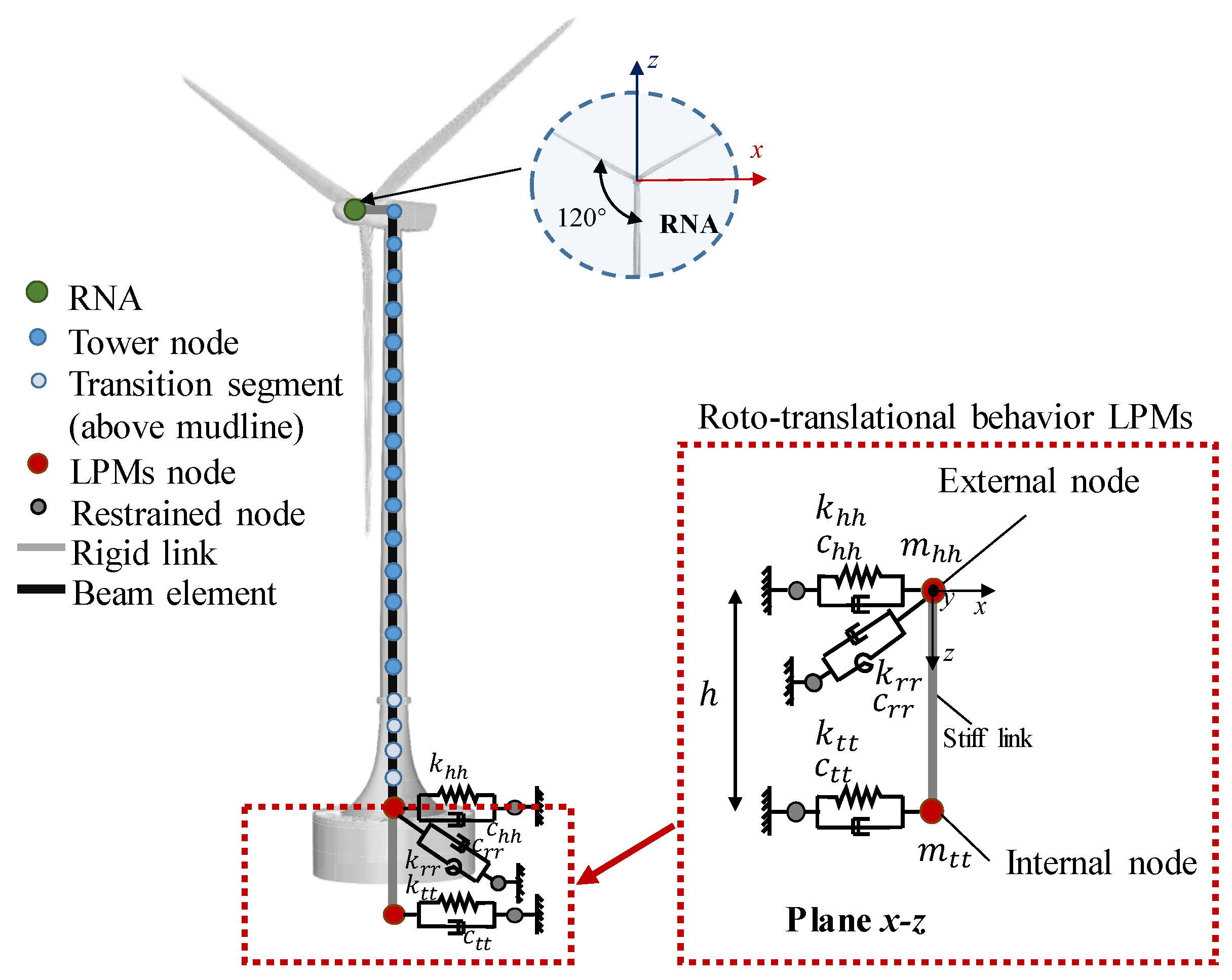
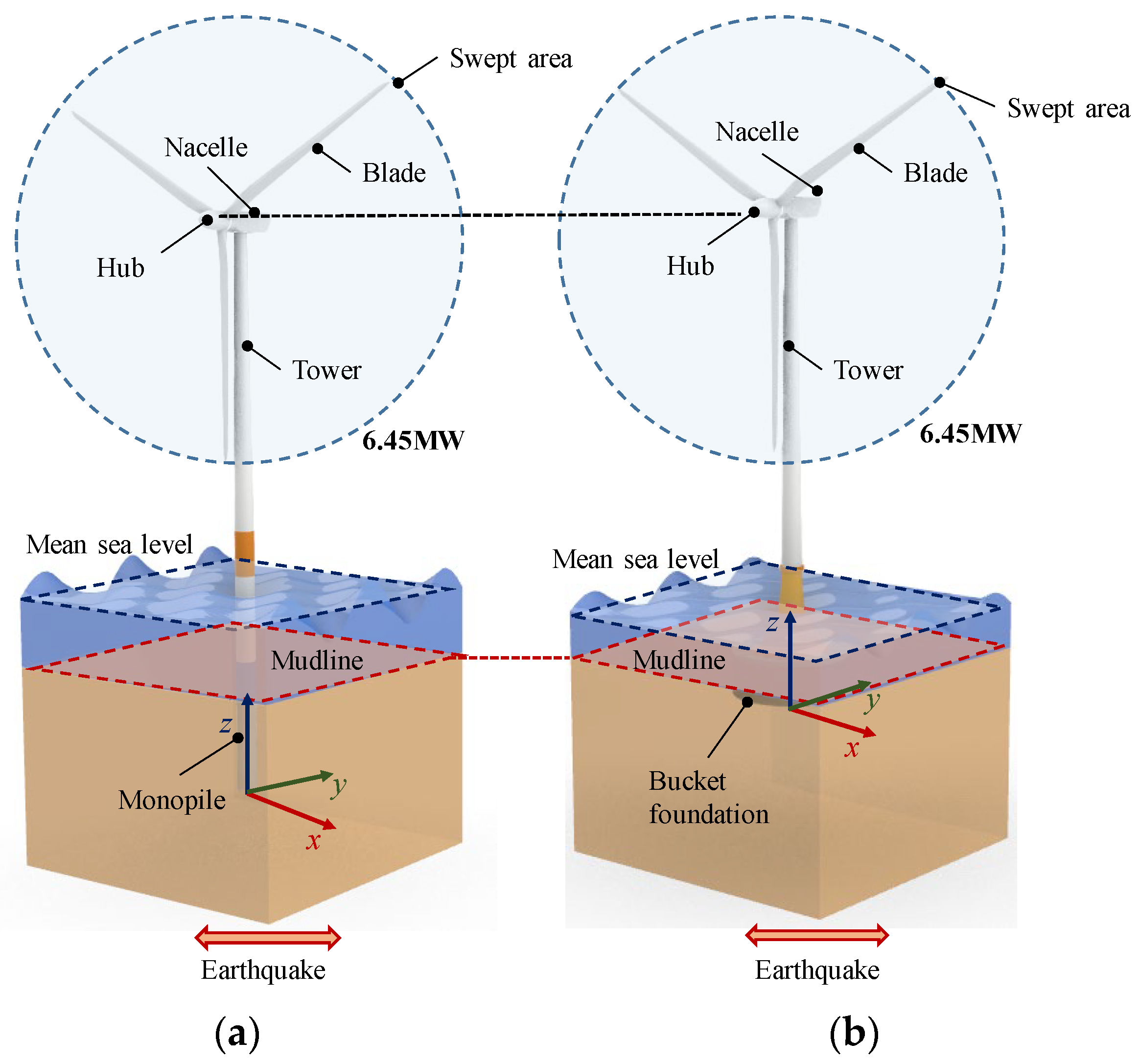
In this paper, a 6.45 MW reference bucket-supported offshore wind turbine located in the southeastern coastal region of China is employed for this case study, as shown in Figure 1. Table 1 presents the key dimensions and physical parameters of the offshore wind turbine.
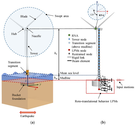
Figure 1.
Schematic of the bucket-supported offshore wind turbine: (a) prototype and (b) numerical model based on a lumped parameter model.

Table 1.
Key parameters of the reference bucket-supported offshore wind turbine.
2.1.1. Bucket Foundation Impedance Functions
As indicated in Table 1, with a slenderness ratio (depth-to-diameter ratio) of 0.33 (<0.5), the bucket foundation for the reference wind turbine in this study is categorized as a wide-shallow bucket foundation [51]. The primary deformation mode of the foundation is rigid rotation, and excessive horizontal displacement can lead to soil punching failure [52]. He et al. [53] indicated that when the slenderness ratio of a bucket foundation is less than 1, the foundation can be considered to be rigid. This assumption has been widely adopted by numerous scholars to investigate the static characteristics [54] and dynamic properties [27,55,56,57] of bucket foundations. In this study, the bucket foundation is also treated as being rigid, and the dynamic impedance functions are derived based on the four-spring Winkler model, as proposed by Gerolymos and Gazetas [58] for rigid caisson foundations. As illustrated in Figure 2, four types of complex springs are employed to simulate the interactions between the soil and foundation, which are combined with dampers: concentrated translational and rotational complex springs (, ) at the bottom of the foundation and distributed translational and rotational complex springs (, ) along the sidewall of the foundation.
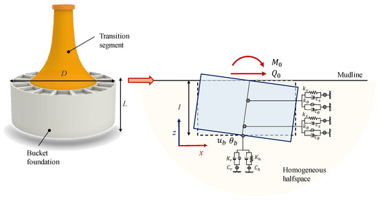
Figure 2.
Four-spring Winkler model for the impedance of bucket foundations.
Based on the D’Alembert principle, the vibration equation for the bucket foundation is derived through force equilibrium:
where , , and denote the mass, stiffness, and damping matrices of the bucket foundation, respectively. is the external force vector, as expressed in Equation (2). This study focuses on horizontal seismic excitation, and responses are obtained in the horizontal direction. and represent the displacement and rotation at the foundation base, respectively. , , and represent the mass, total length, and mass moment of inertia, respectively.
The definition of the dynamic impedance function is the ratio between the harmonic excitation force and the displacement at the top foundation. Therefore, the dynamic impedance matrix, referred to as the base of the bucket, can be represented by Equation (4). According to the coordinate transformation, the impedance of the bucket foundation can be expressed as Equation (5):
where is the complex stiffness matrix of the foundation. and represent the horizontal and rocking impedance functions, respectively, while and are the coupled horizontal-rocking impedance functions.
According to the four-spring Winkler model depicted in Figure 1b, the complex stiffness matrix of the foundation , referred to as the base of the bucket, can be derived through the integration and accumulation of the reaction forces from multiple springs:
where and represent the concentrated translational and rotational complex stiffness matrices, respectively, while and represent the distributed translational and rotational complex stiffness matrices, respectively. represents the embedded length of the bucket foundation. If the bucket is completely embedded, when considering the scour depth (), then .
The impedance functions of foundations on the half-space surface [59] are used to represent the concentrated translational and rotational complex stiffness matrices of the bucket [60,61].
where and represent the horizontal static and dynamic stiffness coefficients of foundations on the half-space surface, respectively; denotes the horizontal damping coefficient, which can simultaneously reflect the radiation damping and material damping of soil; represents the diameter of the bucket foundation; , , , and represent the shear modulus, Poisson’s ratio, density, and shear wave velocity of soil, respectively, as shown in Table 2; and represents the hysteretic damping (material damping), which is frequency-independent and typically ranges from 0.03 to 0.06 [62].
where and denote the rocking static and dynamic stiffness coefficients of foundations on the half-space surface, respectively; represents the rocking damping coefficient, which can simultaneously reflect soil radiation damping and material damping; is the dimensionless frequency; and represents the radiation damping coefficient, which can be obtained from Gazetas [59].
Table 2.
Soil properties.
When treating the bucket foundation as an embedded rigid foundation, the dynamic impedance can also be determined as follows [59,60,62,63]:
where and represent the horizontal and rocking impedances of the embedded foundations, respectively, and and are the coupled horizontal-rocking impedances of the embedded foundations.
where and represent the horizontal dynamic stiffness and damping coefficient of the embedded foundations, respectively; represents the horizontal embedment factor (Gerolymos and Gazetas, 2006); denotes the horizontal dynamic stiffness coefficient of the embedded foundations; and is the ‘Lysmer’s analog’ velocity.
where and are the rocking dynamic stiffness and damping coefficient of the embedded foundations, respectively; is the rocking embedment factor [58,61]; and is the rocking dynamic stiffness coefficient of the embedded foundations.
To ensure the equality of the main diagonal elements and similarity of the off-diagonal elements of matrices (Equation (6)) and (Equation (15)), the complex spring stiffness matrix along the sidewall of the bucket foundation is derived [58]:
Based on Equations (3)–(6), the dynamic impedance functions of the bucket foundation can be obtained, including the horizontal (), rocking (), and coupled horizontal-rocking impedance components (, ).
2.1.2. Lumped Parameter Model Considering the SSI
To facilitate nonlinear time-domain analysis of the offshore wind turbine, a frequency-independent lumped parameter model of the bucket foundation is employed to account for the SSI effect. This model, consisting of several linear springs, dampers, and mass blocks [35,64], is obtained by fitting impedance functions of the soil–foundation system using the least squares method. Additionally, the parameters in this model are frequency-independent. Therefore, direct substitution of the soil–foundation in the time-domain analysis of the superstructure is allowed, resulting in a significant increase in computational efficiency. Various lumped parameter models have been proposed by many scholars [35,37,38,39,40,42,64]. The LPM introduced by Dezi et al. [35] features a reduced number of undetermined parameters (only nine, as depicted in Figure 3) and a simpler model architecture, which is chosen in this study for its simplicity and efficiency over alternative models, with the impedance function expressed by Equations (28)–(30).
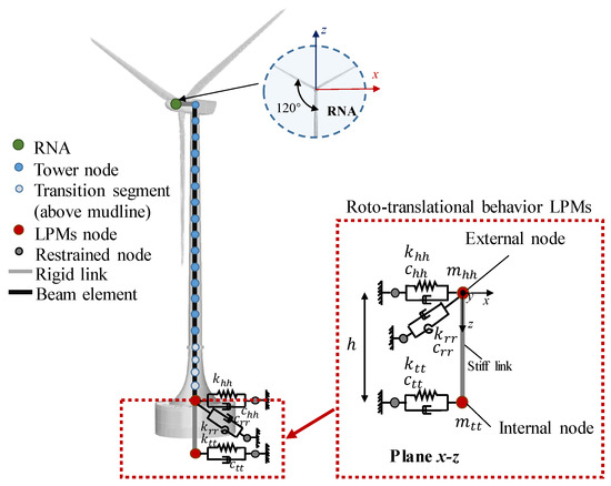
Figure 3.
A lumped parameter model for the bucket foundation.
2.1.3. Integral Model of the Wind Turbine System
Based on the OpenSees platform, a comprehensive numerical model of the bucket-supported OWT is constructed, as illustrated in Figure 1b. Due to its object-oriented nature, OpenSees requires the writing of a Tcl code file with commands to define the model, materials, boundary conditions, and seismic loading. Subsequently, the script is run in an OpenSees interpreter for seismic analysis of the OWT. The modeling environment is three-dimensional with six degrees of freedom. A lumped parameter model is employed at the mudline to constrain the superstructure above the mudline, including the transition segment, tower, and rotor-nacelle assembly (RNA). To incorporate varying cross-sectional properties, the transition segment and tower are divided into 25 and 34 segments, respectively, each of which is equipped with distinct properties. These segments are established using displacement-based beam-column elements. Subsequently, the nacelle and blades are simplified as concentrated masses. Considering the geometric dimensions of the nacelle, a rigid link element is utilized to simulate the distance from the center of the mass to the top of the tower.
Additionally, water–structure interactions impact the dynamic responses of offshore wind turbines and can be represented in seismic analysis using the water-equivalent additional mass. The transition segment between the bucket foundation and the tower can be simplified as a frustum-shaped foundation, as indicated in Figure 4a. To calculate the water-equivalent additional mass, the simplified formulas proposed by Wang et al. [65], which were derived using finite element techniques, are employed. A dimensionless parameter b is introduced (). It should be highlighted that the simplified formulas apply to foundations with and . In this study, the width-to-depth ratio of the simplified transition segment is 0.643 with a slope angle of 63°, which falls within the effective range. Then, based on Equations (31-40), the distribution curve of the additional mass density along the foundation height is calculated and illustrated in Figure 4b.
where represents the additional mass per unit volume; denotes the foundation radius; is the top radius of the foundation; represents the slope angle; indicates the distance of the segment element from the mudline; represents the water depth; and is the water density.
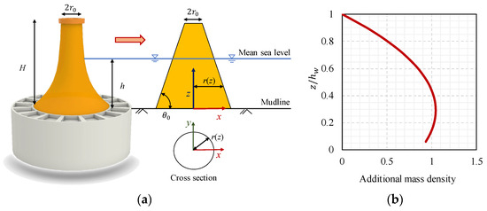
Figure 4.
Additional mass density along the foundation height: (a) schematic representation and (b) distribution curve.
2.1.4. Simulation of Scoured Conditions
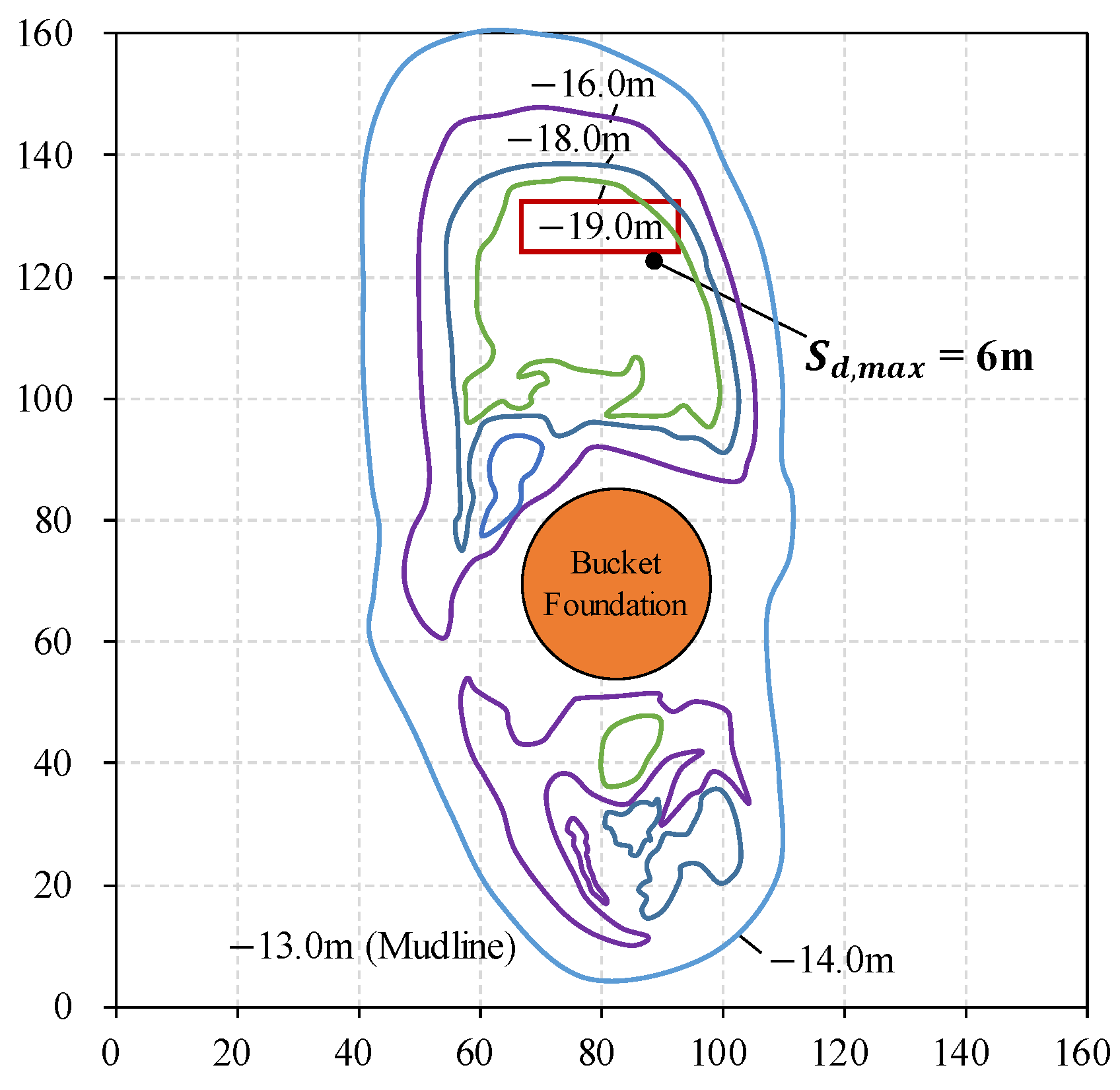
Scour phenomena refer to the erosion or removal of sediment from the bed induced by wave–current actions [66,67,68]. They naturally occur around structures such as offshore wind turbine foundations, bridges, and piers, compromising their stability and complicating seismic analysis [46]. Scour depth is widely acknowledged as the most significant factor under scoured conditions [69], with limited impacts observed when treating local scour as general scour [70]. Onsite monitoring data (see Figure 5) indicate that a southeast-oriented scour hole formed within a 100 m radius of the foundation center, and the scour phenomena were more pronounced within a radius of 36 m. The maximum scour depth relative to the mudline was approximately 6.05 m (0.5 L). In other studies, scholars have typically defined the range of scour depths of bucket foundations as 0.3–0.5 L [24,48,71]. Therefore, this study concentrates on how scour depth affects the seismic responses of OWTs. For demonstration purposes, scour depths are set to 0, 0.1 L, 0.3 L, and 0.5 L.
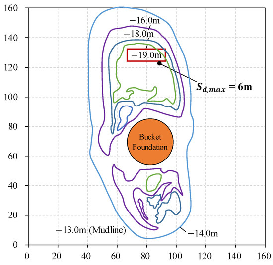
Figure 5.
Erosion topographic map for the bucket foundation.
2.2. Validation
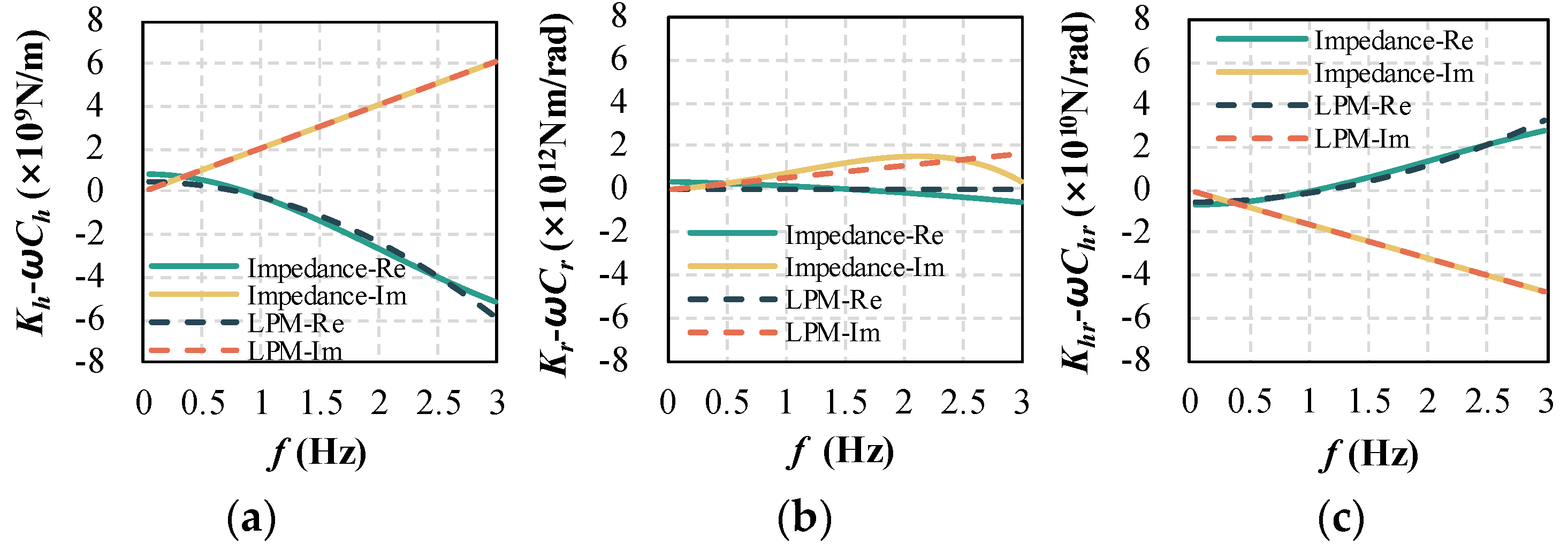
The feasibility of the present study is validated by developing the same model of the 6.45 MW OWT based on the three-dimensional finite element method. This method is widely recognized as relatively accurate and has been adopted by numerous scholars for seismic analyses of bucket-supported OWTs [18,19,20,21,22,23,24]. The Mohr–Coulomb model has been used to simulate soil, with the wind tower and bucket foundation modeled using linear isotropic material with C3D8R elements. Figure 6 shows the impedance functions of the bucket foundation and the corresponding LPM fittings, which are used to establish the proposed integral model in Section 2.1.3.

Figure 6.
Impedance functions and LPM approximations of the bucket foundation: (a) horizontal; (b) rocking; and (c) coupled horizontal-rocking.
Figure 7 displays first-order natural frequencies and seismic response envelopes of the bucket-supported wind turbine obtained from the present study and the three-dimensional finite element model (FEM) under Kobe excitation (0.15 g). Natural frequencies represent structural vibration modes, and first-order natural frequencies significantly influence system behavior [72,73]. The difference in the natural frequencies between the models is 1.3%, indicating that both models have similar dynamic characteristics. Additionally, the envelope trends along the offshore wind turbine (OWT) show consistent patterns, with the maximum absolute acceleration observed at the middle tower and the maximum absolute displacement at the RNA differing by less than 1% and 2%, respectively. Therefore, the feasibility of the present study is further demonstrated. In addition, the proposed simplified dynamic analysis approach is based on linear elastic theory, while the three-dimensional FEM relies on ideal elastic–plastic theory and can consider material and geometric nonlinearity. Therefore, a higher first-order natural frequency is obtained from the proposed method, which overestimates the soil stiffness, as shown in Figure 7a. As a consequence, there are differences in the seismic responses between the two methods (Figure 7b,c). However, refined modeling (three-dimensional FEM) always demands substantial computational resources, which does not align with the rapid and efficient requirements of preliminary wind turbine design. Nevertheless, it is undeniable that the present study can ensure a certain level of accuracy while significantly improving efficiency. Furthermore, the proposed method for monopile-supported OWTs has also been validated and successfully applied in seismic analyses [44].
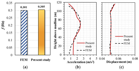
Figure 7.
Comparison between the results from the present study and FEM: (a) natural frequencies, (b) acceleration, and (c) displacement response envelopes along the OWT.
3. Seismic Excitations
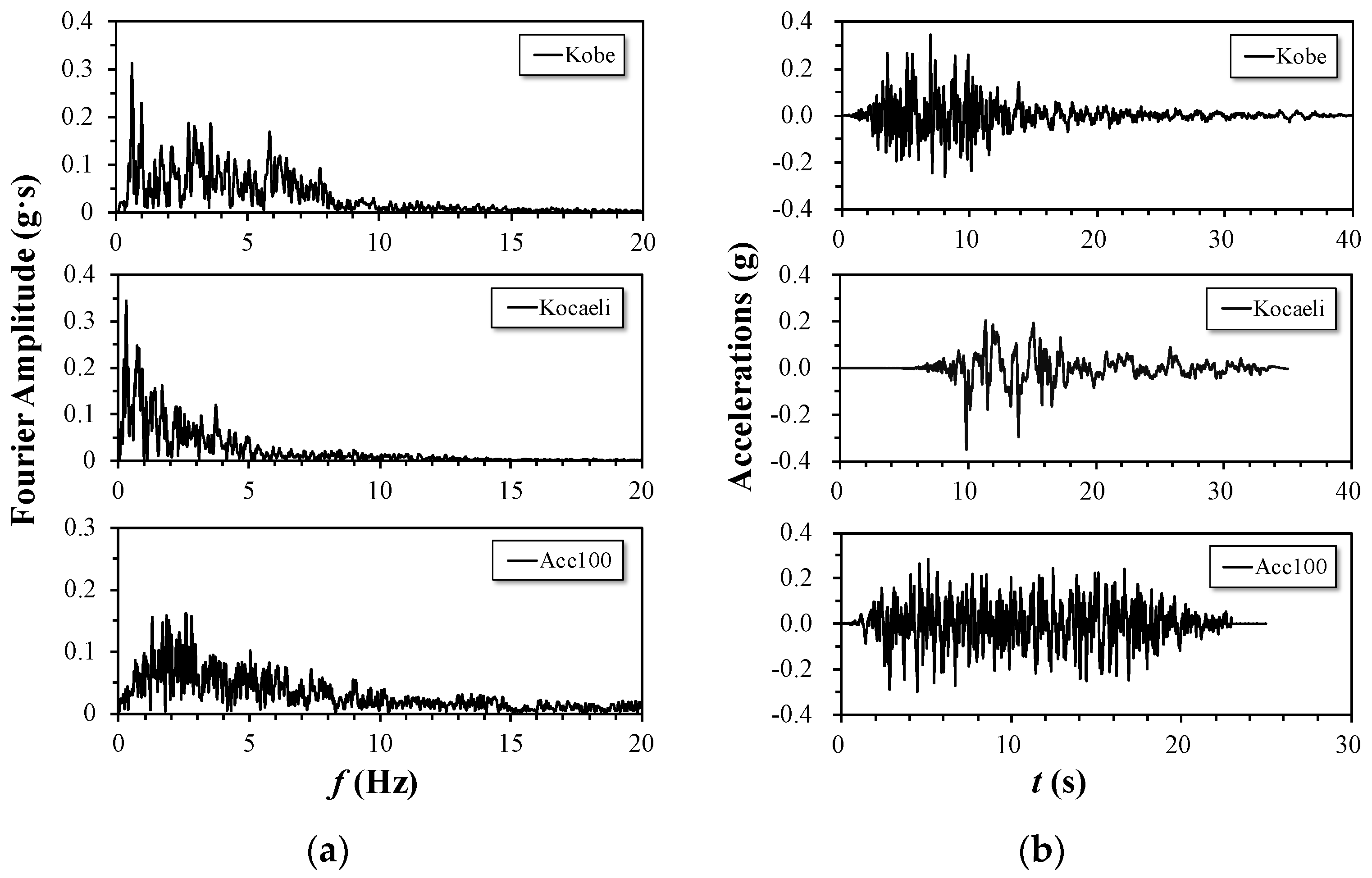
Three earthquakes with different spectral characteristics were chosen as excitations in this study: Kocaeli motion, Kobe motion, and Acc100 motion. Specifically, the Kocaeli and Kobe motions are seismic records derived from significant earthquakes that occurred in Kocaeli, Turkey, and Kobe, Japan, respectively. These motions are based on ground motion recordings from actual seismic events that occurred in these regions. Conversely, Acc100 motion is a synthetic motion derived from the geological conditions of southeastern coastal regions in China [44]. Figure 8 presents the Fourier spectra and acceleration time histories of the chosen earthquakes. The frequencies of the Kocaeli motion range from approximately 0.14 Hz to 0.36 Hz, while those of the Kobe motion range from 0.586 Hz to 2.94–3.56 Hz. The main frequency range of the Acc100 artificial motion is from 1 to 3 Hz. The amplitudes of each input earthquake are scaled to 0.05 g, 0.15 g, and 0.30 g to study the impact of the seismic intensity on the responses. The accelerations correspond to seismic fortification intensities of 6, 7, and 8 degrees, essentially covering the seismic fortification levels of offshore wind farm areas along the southeastern coast [74].

Figure 8.
(a) Fourier spectra and (b) acceleration time histories of the earthquakes.
4. Results and Discussion
4.1. Effect of Seismic Intensities
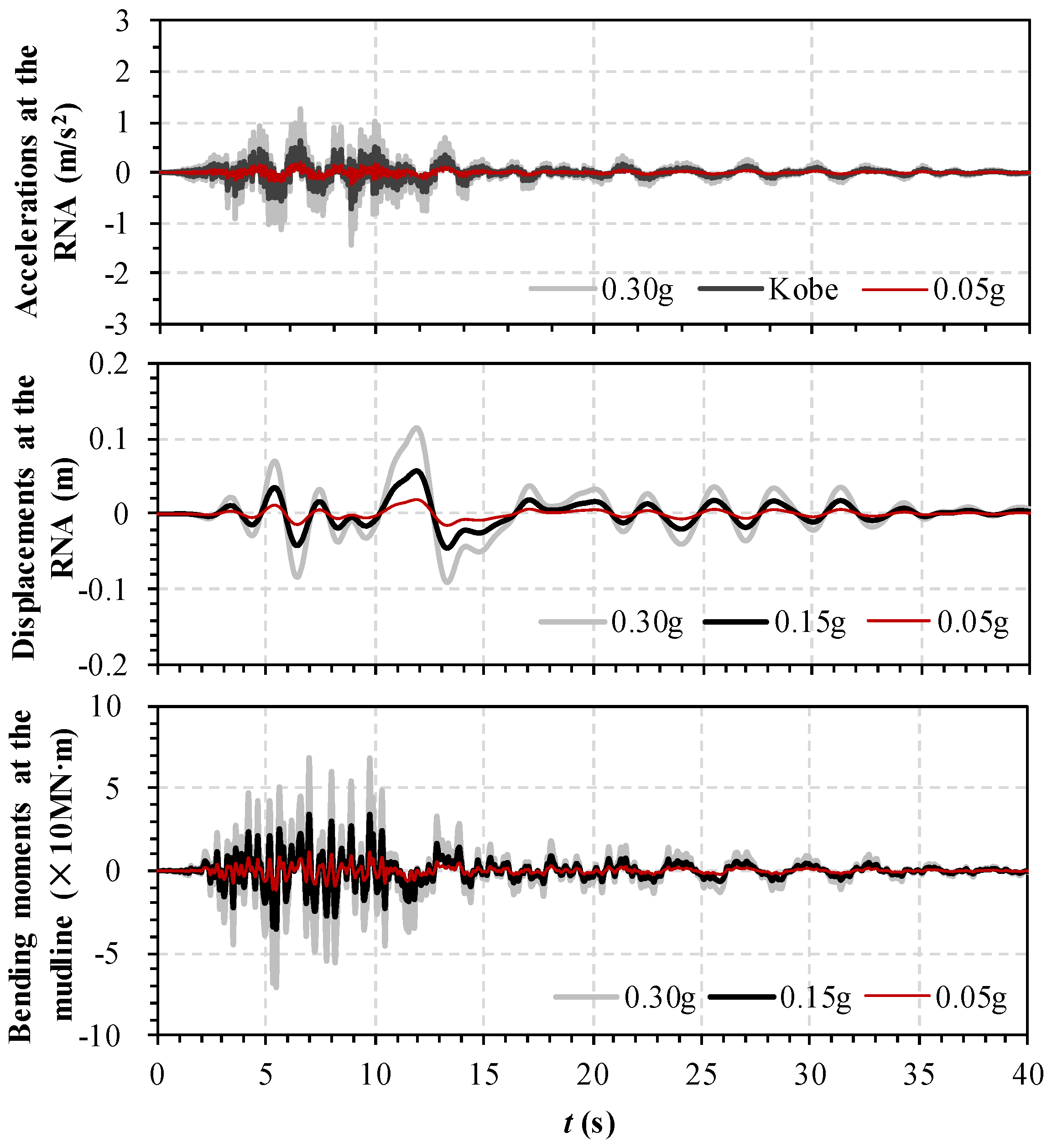
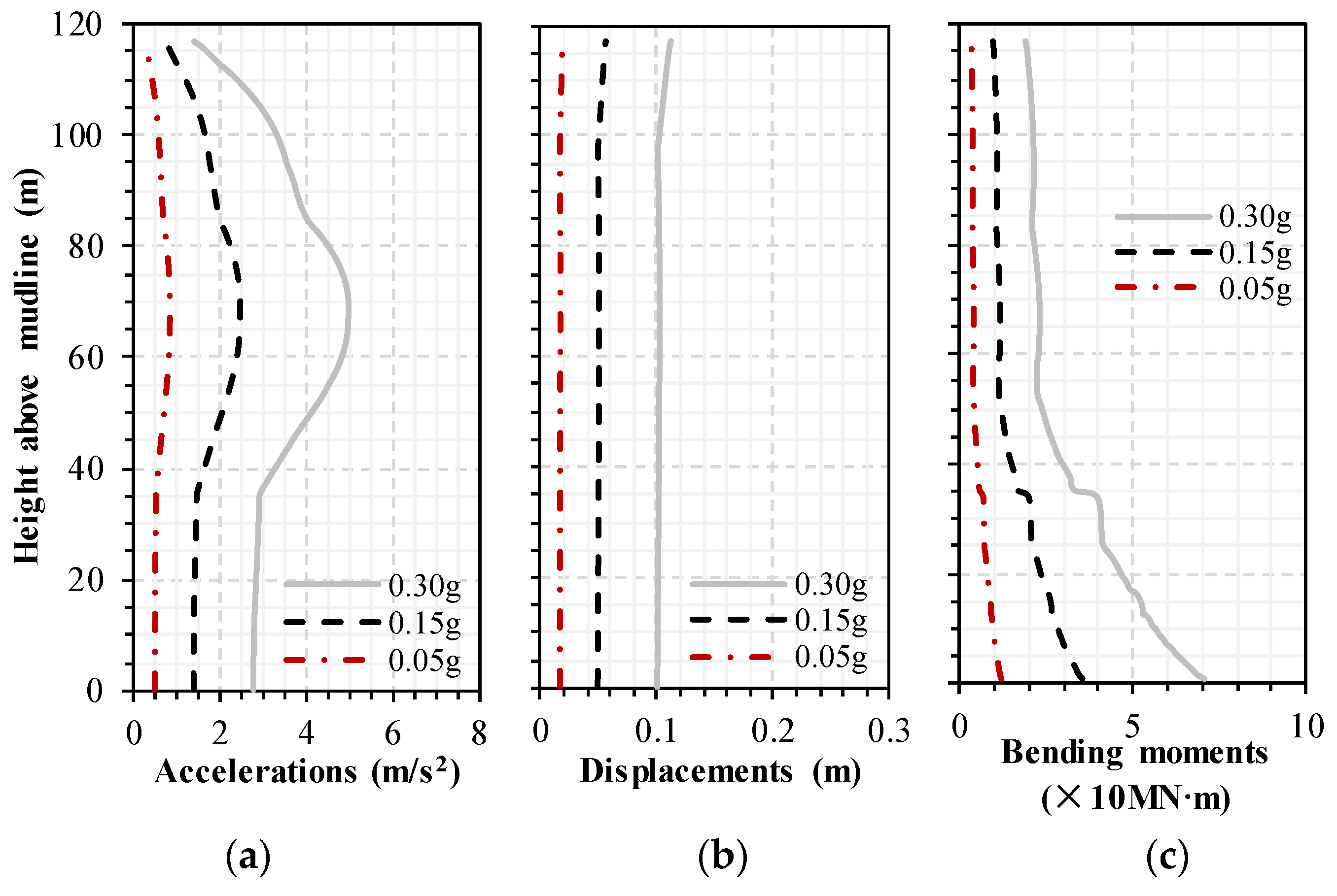
Figure 9 illustrates the time history responses under Kobe excitation with different seismic intensities, including 0.05 g, 0.15 g, and 0.30 g. The seismic responses typically tend toward zero as time progresses, which is generally attributed to energy dissipation by damping [75]. In comparison with the Kobe input motion shown in Figure 8, the filtering effect of the structure on the moderate- to high-frequency components of free-field motions is observed. Moreover, as the seismic intensity increases from 0.05 g to 0.15 g and 0.30 g, respectively, the maximum acceleration, displacement at the RNA, and bending moment at the mudline increase by approximately 67% and 83%, respectively. Figure 10 displays response envelopes for accelerations (Figure 10a), displacements (Figure 10b), and bending moments (Figure 10c) along the OWT. Despite the seismic intensity variations, the response envelope trends remain consistent, with the maximum acceleration, displacement, and bending moment occurring at specific locations: the middle of the tower, the RNA, and the mudline, respectively. With increasing seismic amplitude from 0.05 g to 0.15 g and 0.30 g, the maximum acceleration, displacement, and bending moment of the OWT all increase by approximately 67% and 83%, respectively. The responses exhibit nearly linear increases, suggesting that the wind turbine system predominantly maintains an elastic state within the selected seismic intensity range.
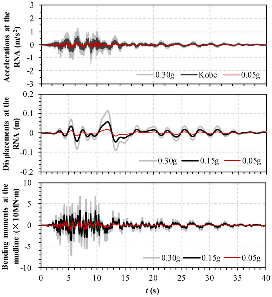
Figure 9.
Time history responses corresponding to accelerations, displacements, and bending moments under different seismic intensities.
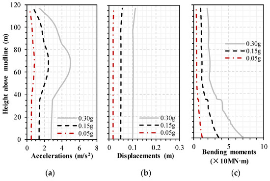
Figure 10.
Response envelopes corresponding to accelerations, displacements, and bending moments along the OWT under different seismic intensities.
4.2. Effect of Seismic Spectral Characteristics
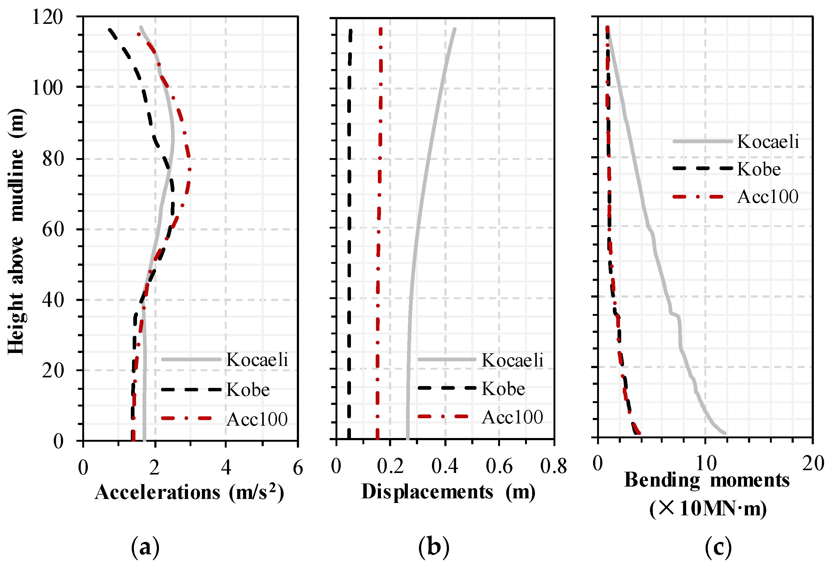
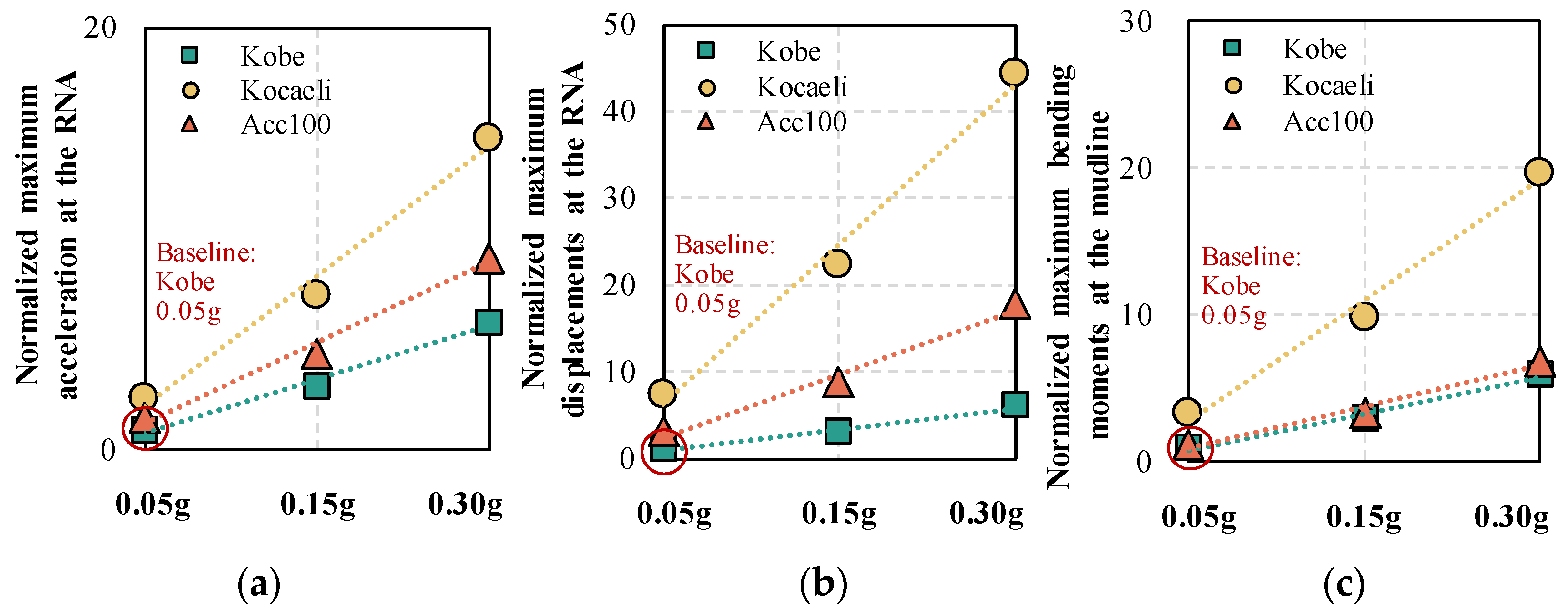
Figure 11 presents the response envelopes under excitations with identical intensities (0.15 g) but different spectral characteristics (Kocaeli, Kobe, and Acc100). The trends of the envelopes remain consistent, with the maximum absolute acceleration (Figure 11a), displacement (Figure 11b), and bending moment (Figure 11c) occurring at specific locations: the middle of the tower, the RNA, and the mudline, respectively. Notably, the seismic responses under Kocaeli motion excitation are more pronounced due to its greater proportion of low-frequency components. Figure 5b indicates that the prominent frequencies of the Kocaeli motion range from approximately 0.14 Hz to 0.36 Hz, closer to the first-order natural frequency of the OWT (0.305 Hz). Conversely, the prominent frequencies of the Kobe motion are relatively distant from the natural frequency of the OWT, resulting in a reduced response under the same seismic amplitude. Therefore, the seismic responses of OWTs are affected not only by the earthquake intensity but also by the seismic spectral characteristics. This finding is consistent with those of other scholars [24,44,46,48,66]. Figure 12 shows the normalized maximum responses corresponding to the accelerations (Figure 12a), displacements (Figure 12b), and bending moments (Figure 12c) under the different earthquakes. Similar to the observations in Figure 10 and Figure 11, the seismic response is amplified when the motion excitation has a higher amplitude or its prominent frequency aligns more closely with the natural frequency of OWTs. Moreover, it is worth noting that the responses exhibit nearly linear increases with increasing seismic intensity, suggesting that the wind turbine system predominantly maintains an elastic state under all selected earthquake excitations. The findings also suggest that the proposed simplified method in this paper is suitable for the seismic analysis of offshore wind turbines when the seismic intensity is less than 0.3 g.
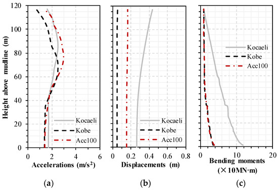
Figure 11.
Response envelopes corresponding to accelerations, displacements, and bending moments along the OWT under different spectral characteristics.
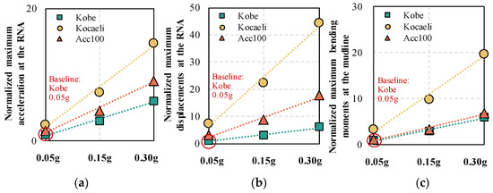
Figure 12.
Normalized maximum responses corresponding to accelerations, displacements, and bending moments under different earthquakes.
4.3. Effect of Foundation Types
In the initial development of offshore wind turbines, monopile foundations emerged as the predominant choice due to their simplicity and cost-effectiveness. To date, more than 70–80% of OWTs are still supported by monopiles [4,46]. Seismic analyses based on lumped parameter models have been extensively conducted to study the performance of monopile-supported OWTs [37,38,39,40,41,42,43,44]. However, investigations into the dynamic characteristics and seismic performance of bucket-supported OWTs still need to be conducted. In this section, numerical models for both bucket-supported and monopile-supported OWTs are constructed using proposed simplified methods based on LPMs. Figure 13 shows a schematic of both physical models. Through a comparison of foundation impedance functions, turbine system characteristics, and seismic response features, the performance of bucket-supported turbines relative to monopile-supported turbines is evaluated. To ensure consistency in parameter analysis, only the foundation type is varied, while other conditions remain unchanged, including the wind farm location (with similar geological conditions), tower height, and turbine size (with the same capacity of 6.45 MW). The dimensions and lumped parameter models of the monopile foundation are derived from Liang et al. [44].

Figure 13.
Schematic of the physical models: (a) monopile-supported offshore wind turbine and (b) bucket-supported offshore wind turbine.
4.3.1. Dynamic Characteristics
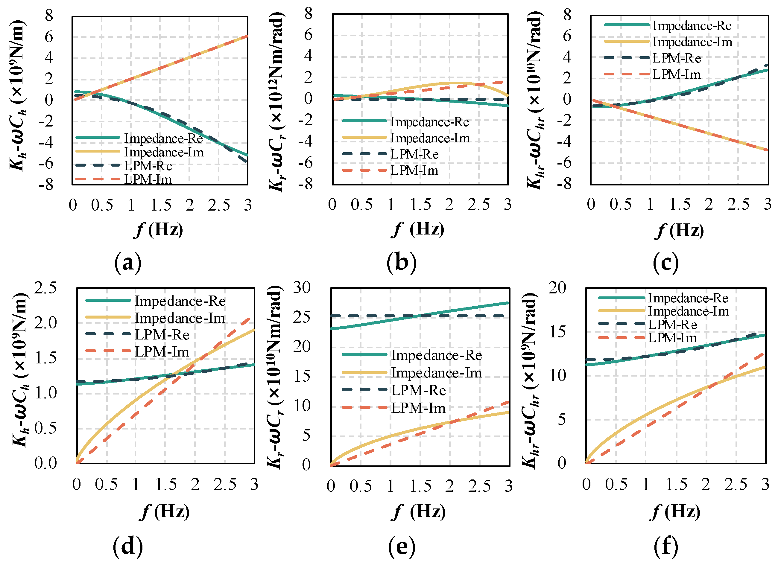
Figure 14 presents the impedance functions and LPM approximations of the bucket and monopile foundations. The positive and negative signs on the vertical axis in the figure represent directionality only. Significant differences are evident in the dynamic impedance functions of the two types of foundations, which are attributed to their distinct load characteristics and dynamic properties. Overall, the wide and shallow bucket foundations demonstrate greater dynamic impedances than monopile impedances, including both dynamic stiffness (real part of the impedance: Re) and damping (imaginary part of the impedance: Im). This indicates substantial disparities in the dynamic characteristics between the two foundation types.
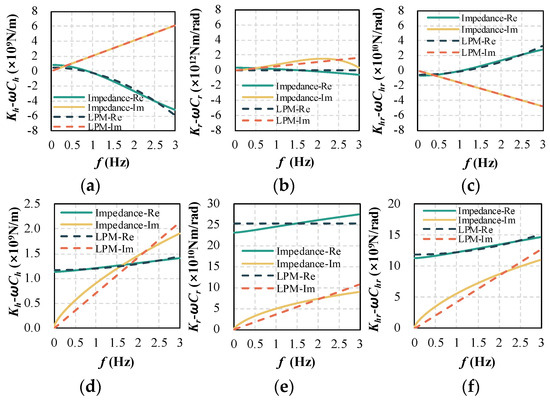
Figure 14.
Impedance functions and LPM approximations of the bucket foundation (a–c) and the monopile (d–f).
Figure 15 shows a comparison of the mode frequencies between the bucket-supported OWT and the monopile-supported OWT, including 16 vibration modes. The first-order natural frequency of the bucket-supported offshore wind turbine system is 0.305 Hz, while that of the monopile-supported turbine system is 0.279 Hz. The dynamic behavior of the bucket-supported OWT is relatively more rigid than that of the monopile-supported OWT under the first mode. This phenomenon may be attributed to the shallow and wide characteristics of the bucket foundation, while the monopiles are relatively slenderer in this study.
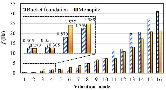
Figure 15.
Mode frequency comparison between the bucket-supported OWT and the monopile-supported OWT.
4.3.2. Seismic Responses
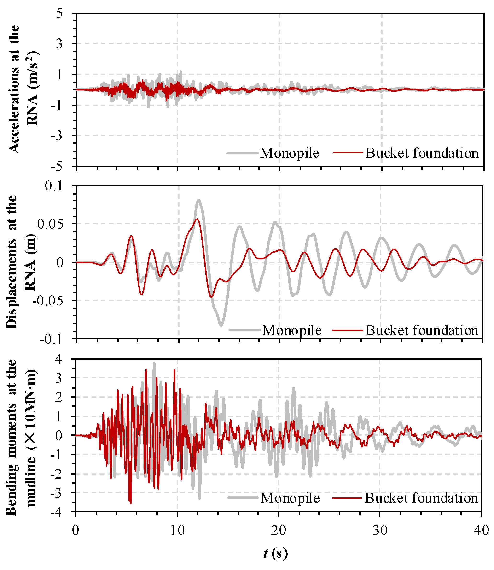
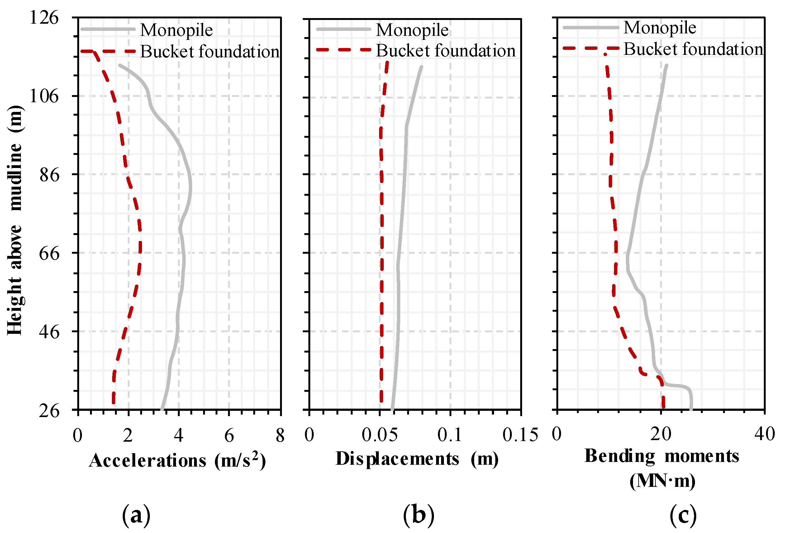
Figure 16 displays the time history responses under the same Kobe motion (0.15 g) excitation with different foundation types. The energy dissipation phenomenon of the bucket-supported OWT is more pronounced, primarily due to the distinct dynamic characteristics exhibited between the bucket and monopile foundations. As illustrated in Figure 14, the bucket foundation exhibits greater dynamic impedances, comprising dynamic stiffness (Impedance-Re) and damping (Impedance-Im). Additionally, the monopile-supported OWT experiences a percentage increase of 46.5% in the maximum acceleration and a percentage increase of 29.0% in the maximum displacement at the RNA, while the maximum bending moment at the mudline is 9.6% greater than that at the bucket-supported OWT. Due to the different foundation types, comparing foundation responses is meaningless, and only tower responses are compared, as shown in Figure 17. The trends of the tower response envelopes remain consistent across different foundation types, with the maximum acceleration (Figure 17a), displacement (Figure 17b), and bending moment (Figure 17c) occurring at specific locations: the middle of the tower, the RNA, and the top of the foundation, respectively. Compared to the bucket-supported OWT, the monopile-supported OWT exhibits 43.9% greater maximum tower acceleration, 30.3% greater maximum tower displacement, and 19.4% greater maximum tower bending moment.

Figure 16.
Time history responses corresponding to accelerations, displacements at the RNA, and bending moments at the mudline for OWTs with different foundation types.
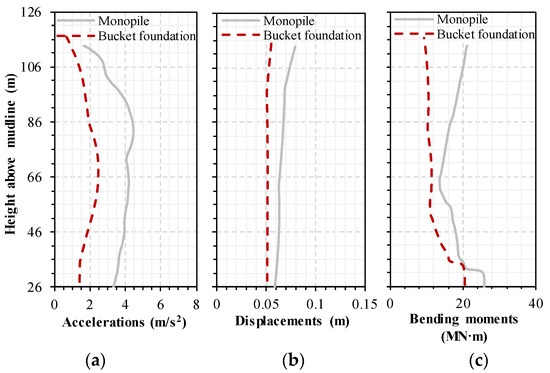
Figure 17.
Response envelopes corresponding to accelerations, displacements, and bending moments along towers with different foundation types.
4.4. Effect of the Scour Depth
4.4.1. Dynamic Characteristics
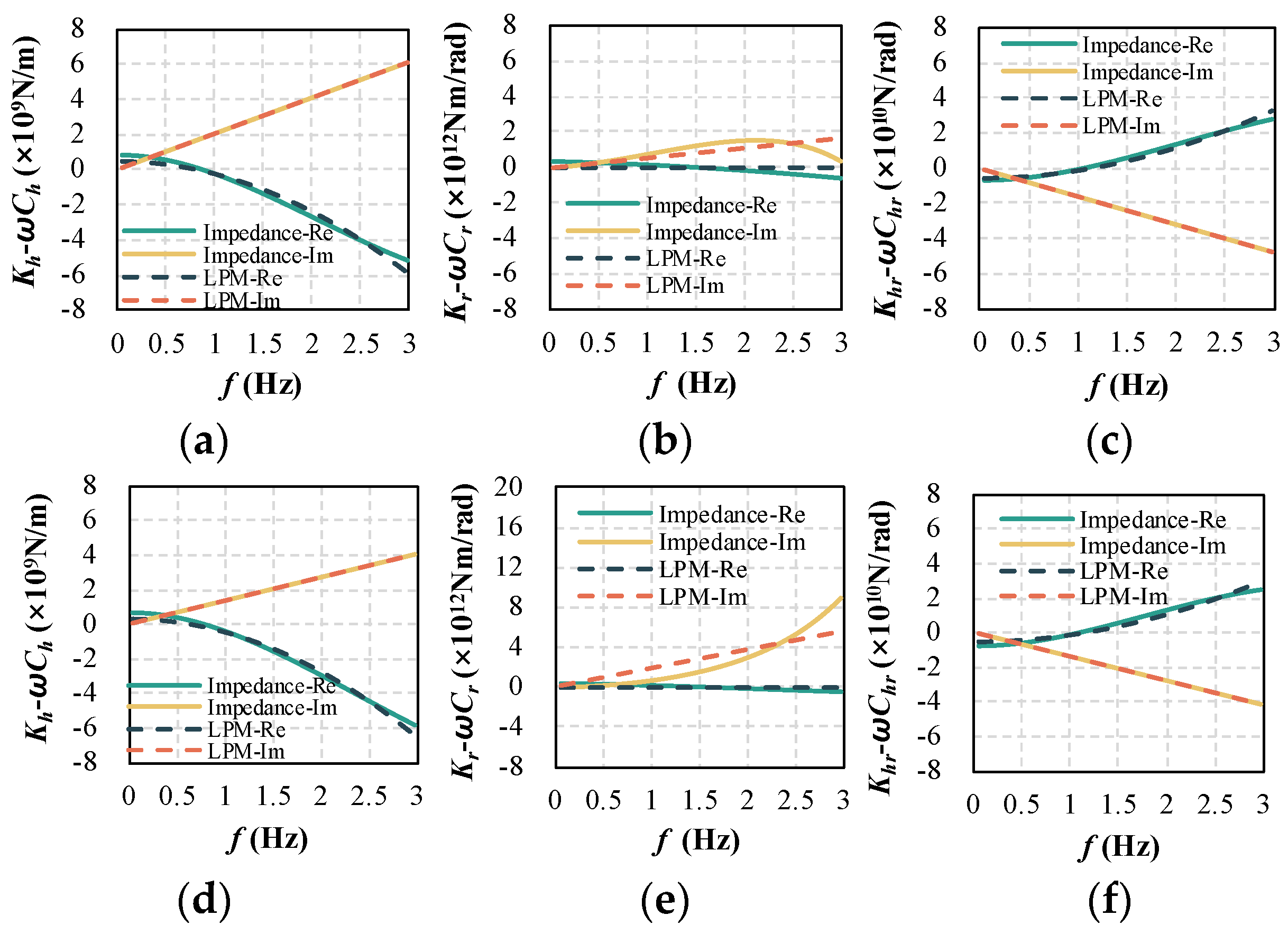
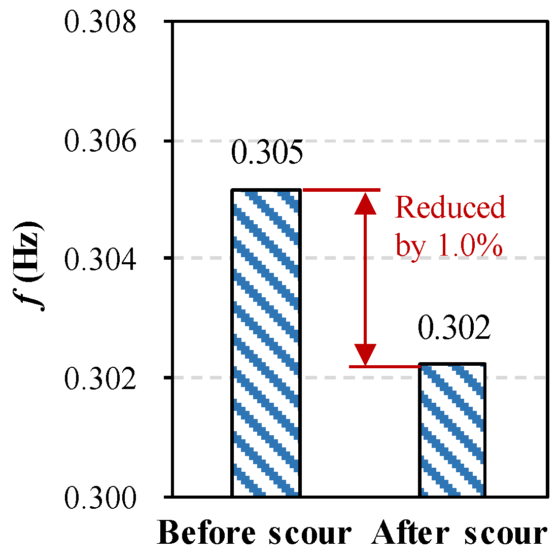
Figure 18 illustrates the impedance functions and LPM approximations of the bucket foundation before and after scour (Sd = 0.5 L). There are changes in the dynamic impedances of the soil–foundation system before and after scour. The scour effects erode the soil around the foundation, resulting in a decrease in soil stiffness, which is the primary cause of the alterations in the dynamic characteristics of the OWT. Therefore, it is essential to account for the scour effect in the dynamic analysis of the soil–foundation system. Figure 19 displays the first-order natural frequency of the bucket-supported OWT before and after scour (Sd = 0.5 L). The soil stiffness decreases after scour, which impacts the stiffness of the bucket-supported offshore wind turbine system, resulting in a decrease in the first-order natural frequency. The dynamic behavior of the bucket-supported OWT is relatively “softer” under scoured conditions.
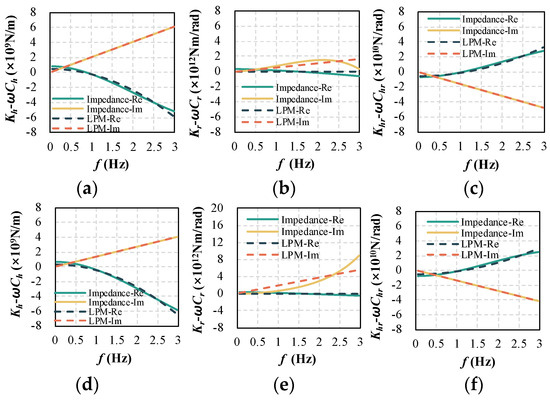
Figure 18.
Impedance functions and LPM approximations of the bucket foundation (a–c) before scour and (d–f) after scour.

Figure 19.
First-order natural frequency of the OWT before and after scour.
4.4.2. Seismic Responses
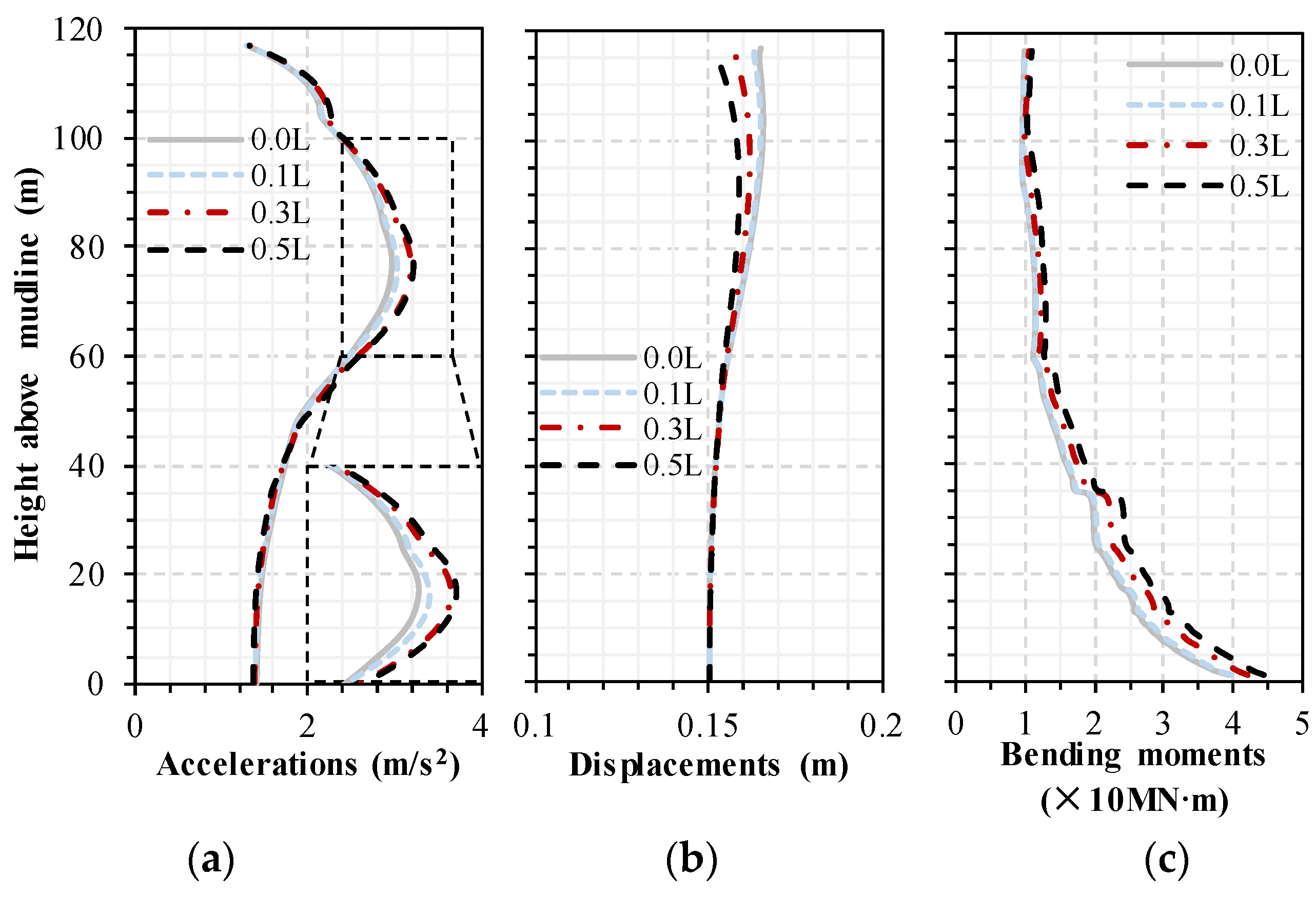
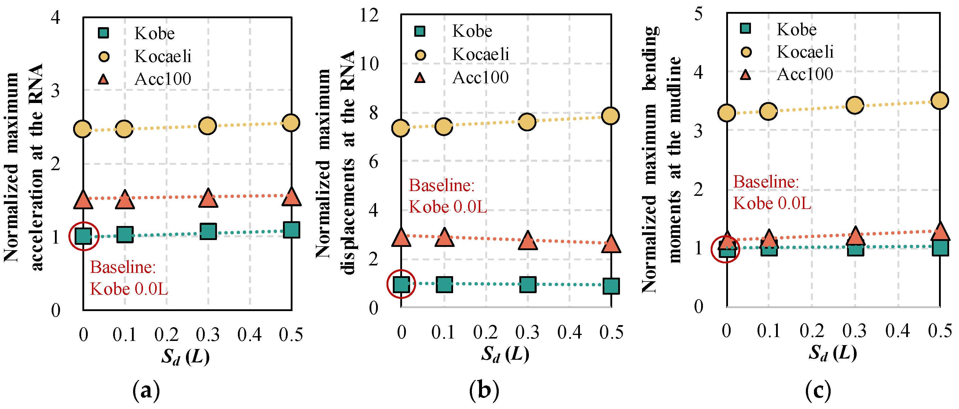
Figure 20 presents response envelopes under the same Acc100 (0.15 g) excitation but with different scour depths, including 0.0 L, 0.1 L, 0.3 L, and 0.5 L. The trends of the envelopes remain consistent, but the response values differ under variable scouring conditions. It is worth noting that with increasing scour depth, the seismic response of the OWT does not necessarily increase. In Figure 20a,b, the maximum acceleration increases by 8.62% when the scour depth reaches 0.5 L, while the maximum displacement decreases by 3.92%. Figure 20c shows that the maximum bending moment is still near the mudline, and it increases by 13.23%. However, under different seismic motions, the changes in seismic responses with increasing scour depth also vary. Figure 21 shows the normalized maximum responses for accelerations (Figure 21a), displacements (Figure 21b), and bending moments (Figure 21c). When the scour depth increases to 0.5 L, the maximum accelerations at the RNA increase by 8.65%, 3.79%, and 2.64% for the Kobe, Kocaeli, and Acc100 excitations, respectively. Conversely, under Kobe and Acc100 excitations, the maximum displacements at the RNA decrease by 8.10% and 9.63%, respectively, while they increase by 6.48% under Kocaeli motion. For the bending moment at the mudline, the maximum increase is 2.1%, 6.28%, and 13.23%, respectively, as shown in Figure 21c. It can be confirmed that scour alters the dynamic characteristics of the system, thereby changing the seismic responses of the OWT. This change may be advantageous, but in most cases, it remains disadvantageous, depending on the spectral characteristics of the seismic excitations. Therefore, it is imperative to account for the scour effect in wind turbine seismic design to mitigate potential risks.
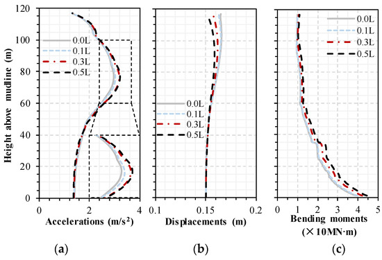
Figure 20.
Response envelopes corresponding to accelerations, displacements, and bending moments along towers under different scouring conditions.
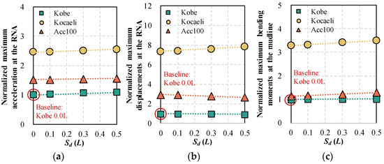
Figure 21.
Normalized maximum responses corresponding to accelerations, displacements at the RNA, and bending moments at the mudline under different scoured conditions.
5. Conclusions
Numerous offshore wind turbines (OWTs) with bucket foundations have been installed in seismic regions. Compared to the relative development of monopiles (widely installed), seismic design guidelines for bucket-supported OWTs still need to be developed. Moreover, the scour phenomenon around bucket foundations induced by water–current actions also creates more challenges to the seismic design of OWTs. In this study, a simplified seismic analysis method is proposed that incorporates the soil–structure interaction (SSI) for the preliminary design of scoured bucket-supported OWTs, aiming to balance accuracy and efficiency. It is worth noting that this paper extends the groundwork established in earlier research [36,44,45,46]. Compared with monopiles [44], this study focuses on bucket foundations and employs a lumped parameter model (LPM) to consider the SSI effect. The model is developed by fitting frequency-dependent impedance functions obtained from the four-spring Winkler model. Additionally, the water–structure interaction is also considered by including additional mass to the transition segment in water during seismic analysis, where the transition is simplified to a frustum-shaped foundation. Then, an integral numerical model of the bucket-supported OWT is constructed based on the OpenSees platform, and the validity of the model is confirmed through comparisons of dynamic characteristics and seismic responses with those obtained from the three-dimensional finite element method. Through a series of parametric analyses, the following conclusions can be drawn:
- As the amplitude of the earthquake decreases from 0.30 g to 0.15 g and 0.05 g, the maximum acceleration, displacement, and bending moment increase by approximately 67% and 83%, respectively.
- The seismic responses under the Kocaeli motion (characterized by abundant low-frequency components) are more pronounced than those under the Kobe and Acc100 excitations. The seismic response is amplified when the prominent frequency of motion closely aligns with the natural frequency of the OWT.
- Compared with the monopile-supported OWT, the bucket-supported OWT demonstrates greater dynamic impedances of foundations and first-order natural frequencies. Additionally, the maximum acceleration, displacement, and bending moment of the monopile-supported OWT increase by 43.9%, 30.3%, and 19.4%, respectively.
- Increasing the scour depth (from 0 to 0.5 L) results in a decrease in the soil stiffness, causing alterations in the impedance functions and frequency characteristics of the OWT. Moreover, with increasing scour depth, the seismic response of the OWT changes significantly. The effect may be advantageous, but in most cases, it remains disadvantageous, depending on the spectral characteristics of the seismic excitations. Therefore, it is imperative to account for scour phenomena in wind turbine seismic design to mitigate potential risks.
In this study, a linear elastic assumption is employed to derive the dynamic impedance functions of the foundation, aiming to streamline calculations and enhance efficiency. However, nonlinear behavior actually exists not only in soil materials but also in the geometric interface between the foundation and soil, which becomes particularly pronounced during strong earthquakes. Therefore, further research and optimization of the proposed method are necessary. Subsequent adjustments, informed by experimental data, can be made to modify the stiffness and damping. This modification partially accounts for the nonlinear characteristics, thereby enhancing the accuracy of seismic analysis results for wind turbines.
Author Contributions
Conceptualization, F.L. and P.S.; methodology, X.J.; software, X.J.; validation, X.J.; formal analysis, X.J.; investigation, H.Z.; resources, F.L., P.S. and H.Z.; data curation, X.J.; writing—original draft preparation, X.J.; writing—review and editing, F.L. and H.Z.; visualization, X.J. and H.Z.; supervision, F.L., P.S. and H.Z.; project administration, F.L., P.S. and H.Z.; funding acquisition, F.L., P.S. and H.Z. All authors have read and agreed to the published version of the manuscript.
Funding
This research was funded by the Shanghai Investigation, Design & Research Institute Co., Ltd. (Project No. 2022FD(83)-010), the Top Discipline Plan of Shanghai Universities-Class I (Grant No. 2022-3-YB-02), and the Fundamental Research Funds for the Central Universities.
Institutional Review Board Statement
Not applicable.
Informed Consent Statement
Not applicable.
Data Availability Statement
The original contributions presented in the study are included in the article.
Acknowledgments
The above funding support is gratefully acknowledged.
Conflicts of Interest
Author Panpan Shen was employed by the company Shanghai Investigation, Design & Research Institute Co., Ltd. The remaining authors declare that the research was conducted in the absence of any commercial or financial relationships that could be construed as a potential conflict of interest.
Correction Statement
The article has been republished with a minor correction to the reference 43. This change does not affect the scientific of the article
Nomenclature
| mass matrices of the bucket foundation | |
| stiffness matrices of the bucket foundation | |
| damping matrices of the bucket foundation | |
| external force vector | |
| displacement at the foundation base | |
| rotation at the foundation base | |
| mass of the bucket foundation | |
| total length of the bucket foundation | |
| mass moment of inertia | |
| impedance of the bucket foundation | |
| complex stiffness matrix of the bucket foundation | |
| horizontal impedance functions | |
| rocking impedance functions | |
| coupled horizontal-rocking impedance functions | |
| concentrated translational complex stiffness matrices | |
| concentrated rotational complex stiffness matrices | |
| distributed translational complex stiffness matrices | |
| distributed rotational complex stiffness matrices | |
| embedded length | |
| scour depth | |
| , | horizontal static and dynamic stiffness coefficients |
| horizontal damping coefficient | |
| diameter of the bucket foundation | |
| shear modulus | |
| Poisson’s ratio | |
| density | |
| shear wave velocity | |
| hysteretic damping | |
| , | rocking static and dynamic stiffness coefficients |
| rocking damping coefficient | |
| dimensionless frequency | |
| radiation damping coefficient | |
| impedance of the embedded foundation | |
| horizontal impedances of embedded foundations | |
| rocking impedances of embedded foundations | |
| coupled horizontal-rocking impedances of embedded foundations | |
| , | horizontal dynamic stiffness and damping coefficient of embedded foundations |
| horizontal embedment factor | |
| horizontal dynamic stiffness coefficient of embedded foundations | |
| ‘Lysmer’s analogue’ velocity | |
| , | rocking dynamic stiffness and damping coefficient of embedded foundations |
| rocking embedment factor | |
| rocking dynamic stiffness coefficient of embedded foundations | |
| height of transition | |
| additional mass per unit volume | |
| () | the transition radius (top radius) |
| slope angle | |
| distance of the transition element from the mudline | |
| water depth | |
| water density | |
| frequency | |
| OWT | Offshore wind turbine |
| SSI | Soil–structure interaction |
| LPM | Lumped parameter model |
| MSL | Mean sea level |
| RNA | Rotor-nacelle assembly |
| FEM | Finite element model |
References
- Global Wind Energy Council (GWEC). Global Wind Report 2024; Joyce, L., Feng, Z., Eds.; Global Wind Energy Council (GWEC): Brussels, Belgium, 2024. [Google Scholar]
- Barari, A.; Ibsen, L.B. Insight into the lateral response of offshore shallow foundations. Ocean Eng. 2017, 144, 203–210. [Google Scholar]
- Lian, J.; Zhao, Y.; Dong, X.; Lian, C.; Wang, H. An experimental investigation on long-term performance of the wide-shallow bucket foundation model for offshore wind turbine in saturated sand. Ocean Eng. 2021, 228, 108921. [Google Scholar] [CrossRef]
- Gupta, B.K.; Basu, D. Offshore wind turbine monopile foundations: Design perspectives. Ocean Eng. 2020, 213, 107514. [Google Scholar] [CrossRef]
- Ding, H.; Liu, Y.; Zhang, P.; Le, C. Model tests on the bearing capacity of wide-shallow composite bucket foundations for offshore wind turbines in clay. Ocean Eng. 2015, 103, 114–122. [Google Scholar] [CrossRef]
- Jia, N.; Zhang, P.; Liu, Y.; Ding, H. Bearing capacity of composite bucket foundations for offshore wind turbines in silty sand. Ocean Eng. 2018, 151, 1–11. [Google Scholar] [CrossRef]
- Ding, H.; Hu, R.; Zhang, P.; Le, C. Load bearing behaviors of composite bucket foundations for offshore wind turbines on layered soil under combined loading. Ocean Eng. 2020, 198, 106997. [Google Scholar] [CrossRef]
- Wang, X.; Zhang, P.; Ding, H.; Liu, Y. Experimental study on wide-shallow composite bucket foundation for offshore wind turbine under cyclic loading. Mar. Georesources Geotechnol. 2019, 37, 1–13. [Google Scholar] [CrossRef]
- Zheng, X.Y.; Li, H.; Rong, W.; Li, W. Joint earthquake and wave action on the monopile wind turbine foundation: An experimental study. Mar. Struct. 2015, 44, 125–141. [Google Scholar] [CrossRef]
- De Risi, R.; Bhattacharya, S.; Goda, K. Seismic performance assessment of monopile-supported offshore wind turbines using unscaled natural earthquake records. Soil Dyn. Earthq. Eng. 2018, 109, 154–172. [Google Scholar] [CrossRef]
- Elgamal, A.W.; Kim, K.; Zayed, M. Seismic response of suction caisson in large-scale shake table test. In Proceedings of the Conference: VII international Conference on Earthquake Geotechnical Engineering, Rome, Italy, 17–20 June 2019. [Google Scholar]
- Haddad, A.; Barari, A.; Amini, R. The remedial performance of suction caisson foundations for offshore wind turbines under seismically induced liquefaction in the seabed: Shake table testing. Mar. Struct. 2022, 83, 103171. [Google Scholar] [CrossRef]
- Zhang, P.; Li, J.; Le, C.; Ding, H. Seismic responses of two bucket foundations for offshore wind turbines based on shaking table tests. Renew. Energy 2022, 187, 1100–1117. [Google Scholar] [CrossRef]
- Houlsby, G.T.; Kelly, R.B.; Huxtable, J.; Byrne, B.W. Field trials of suction caissons in sand for offshore wind turbine foundations. Géotechnique 2006, 56, 3–10. [Google Scholar] [CrossRef]
- Yu, H.; Zeng, X.; Li, B.; Lian, J. Centrifuge modeling of offshore wind foundations under earthquake loading. Soil Dynam. Earthq. Eng. 2015, 77, 402–415. [Google Scholar] [CrossRef]
- Wang, X.; Yang, X.; Zeng, X. Seismic centrifuge modelling of suction bucket foundation for offshore wind turbine. Renew. Energy 2017, 114, 1013–1022. [Google Scholar] [CrossRef]
- Ueda, K.; Uzuoka, R.; Iai, S.; Okamura, T. Centrifuge model tests and effective stress analyses of offshore wind turbine systems with a suction bucket foundation subject to seismic load. Soils Found. 2020, 60, 1546–1569. [Google Scholar] [CrossRef]
- Zhang, P.; Ding, H.; Le, C. Seismic response of large-scale prestressed concrete bucket foundation for offshore wind turbines. J. Renew. Sustain. Energy 2014, 6, 013127. [Google Scholar] [CrossRef]
- Zhang, P.; Xiong, K.; Ding, H.; Le, C. Anti-liquefaction characteristics of composite bucket foundations for offshore wind turbines. J. Renew. Sustain. Energy 2014, 6, 053102. [Google Scholar] [CrossRef]
- Zhang, J.; Cheng, W.; Cheng, X.; Wang, P.; Wang, T. Seismic responses analysis of suction bucket foundation for offshore wind turbine in clays. Ocean Eng. 2021, 232, 109159. [Google Scholar] [CrossRef]
- Eslami, A.; Ghorbani, A. Seismic response of offshore wind turbines supported on Monopiles and Suction Buckets: Numerical modelling and soft computing study. Soil Dynam. Earthq. Eng. 2022, 159, 107284. [Google Scholar] [CrossRef]
- Wang, X.; Ma, C.; Li, J. Seismic response of suction bucket foundation for offshore wind turbines: A parametric study. Ocean Eng. 2022, 257, 111570. [Google Scholar] [CrossRef]
- Cheng, X.; Cheng, W.; Wang, P.; El Naggar, M.H.; Zhang, J.; Liu, Z. Response of offshore wind turbine tripod suction bucket foundation to seismic and environmental loading. Ocean Eng. 2022, 257, 111708. [Google Scholar] [CrossRef]
- Li, J.; Lian, J.; Guo, Y.; Wang, H. Seismic response and liquefaction characteristics of wide and shallow multi-bucket jacket foundation under scour conditions. Ocean Eng. 2023, 287, 115816. [Google Scholar] [CrossRef]
- Alati, N.; Failla, G.; Arena, F. Seismic analysis of offshore wind turbines on bottom-fixed support structures. Philos. Trans. R. Soc. A Math. Phys. Eng. Sci. 2015, 373, 20140086. [Google Scholar] [CrossRef] [PubMed]
- Seong, J.T.; Ha, J.G.; Kim, J.H.; Park, H.J.; Kim, D.S. Centrifuge modeling to evaluate natural frequency and seismic behavior of offshore wind turbine considering SFSI. Wind Energy 2017, 20, 1787–1800. [Google Scholar] [CrossRef]
- Andersen, L.; Ibsen, L.B.; Liingaard, M. Impedance of bucket foundations: Torsional, horizontal and rocking motion. In Proceedings of the Sixth International Conference on Engineering Computational Technology, Athens, Greece, 2–5 September 2008. [Google Scholar]
- Andersen, L.; Ibsen, L.B.; Liingaard, M. Lumped-parameter model of a bucket foundation. In Proceedings of the 1st International Symposium on Computational Geomechanics (COMGEO I), Juan-les-Pins, France, 29 May 2009. [Google Scholar]
- Suryasentana, S.K.; Byrne, B.W.; Burd, H.J.; Shonberg, A. An elastoplastic 1D Winkler model for suction caisson foundations under combined loading. In Proceedings of the Ninth European Conference on Numerical Methods in Geotechnical Engineering, Porto, Portugal, 25–27 June 2018. [Google Scholar]
- Antoniou, M.; Kourkoulis, R.; Gelagoti, F.; Anastasopoulos, I. Simplified method for performance-based seismic design of suction caissons supporting jacket offshore wind turbines. Soil Dynam. Earthq. Eng. 2022, 155, 107169. [Google Scholar] [CrossRef]
- Tsigginos, C.; Gerolymos, N.; Assimaki, D.; Gazetas, G. Seismic response of bridge pieron rigid caisson foundation in soil stratum. Earthq. Eng. Eng. Vib. 2008, 7, 33. [Google Scholar] [CrossRef]
- Skau, K.S.; Grimstad, G.; Page, A.M.; Eiksund, G.R.; Jostad, H.P. A macro-element for integrated time domain analyses representing bucket foundations for offshore wind turbines. Mar. Struct. 2018, 59, 158–178. [Google Scholar] [CrossRef]
- Skau, K.S.; Jostad, H.P.; Eiksund, G.; Sturm, H. Modelling of soil-structure-interaction for flexible caissons for offshore wind turbines. Ocean Eng. 2019, 171, 273–285. [Google Scholar] [CrossRef]
- Li, H.; Lian, J.; Liu, R.; Wang, H.; Yang, X. Research on the equivalent stiffness of bucket foundations for offshore wind power. Ocean Eng. 2024, 302, 117596. [Google Scholar] [CrossRef]
- Dezi, F.; Carbonari, S.; Tombari, A.; Leoni, G. Soil-structure interaction in the seismic response of an isolated three span motorway overcrossing founded on piles. Soil Dynam. Earthq. Eng. 2012, 41, 151–163. [Google Scholar] [CrossRef]
- Liang, F.; Zhang, H.; Huang, M. Influence of flood-induced scour on dynamic impedances of pile groups considering the stress history of undrained soft clay. Soil Dynam. Earthq. Eng. 2017, 96, 76–88. [Google Scholar] [CrossRef]
- Damgaard, M.; Andersen, L.V.; Ibsen, L.B. Computationally efficient modelling of dynamic soil–structure interaction of offshore wind turbines on gravity footings. Renew. Energy 2014, 68, 289–303. [Google Scholar] [CrossRef]
- Damgaard, M.; Zania, V.; Andersen, L.V.; Ibsen, L.B. Effects of soil–structure interaction on real time dynamic response of offshore wind turbines on monopiles. Eng. Struct. 2014, 75, 388–401. [Google Scholar] [CrossRef]
- Damgaard, M.; Andersen, L.V.; Ibsen, L.B. Dynamic response sensitivity of an offshore wind turbine for varying subsoil conditions. Ocean Eng. 2015, 101, 227–234. [Google Scholar] [CrossRef]
- Damgaard, M.; Andersen, L.V.; Ibsen, L.B.; Toft, H.S.; Sørensen, J.D. A probabilistic analysis of the dynamic response of monopile foundations: Soil variability and its consequences. Probabilistic Eng. Mech. 2015, 41, 46–59. [Google Scholar] [CrossRef]
- Taddei, F.; Schauer, M.; Meinerzhagen, L. A practical soil-structure interaction model for a wind turbine subjected to seismic loads and emergency shutdown. Procedia Eng. 2017, 199, 2433–2438. [Google Scholar] [CrossRef]
- Padrón, L.A.; Carbonari, S.; Dezi, F.; Morici, M.; Bordón, J.D.R.; Leoni, G. Seismic response of large offshore wind turbines on monopile foundations including dynamic soil-structure interaction. Ocean Eng. 2022, 257, 111653. [Google Scholar] [CrossRef]
- Sánchez, C.R.; Padrón, L.A. Implementation of ground input motion and dynamic Soil-Structure Interaction into Openfast for the seismic analysis of offshore wind turbines. In Proceedings of the Congress on Numerical Methods in Engineering (CMN), Las Palmas de Gran Canaria, Spain, 14–16 September 2022. [Google Scholar]
- Liang, F.; Jia, X.; Zhang, H.; Wang, C.; Shen, P. Seismic responses of offshore wind turbines based on a lumped parameter model subjected to complex marine loads at scoured sites. Ocean Eng. 2024, 297, 116808. [Google Scholar] [CrossRef]
- Zhang, H.; Liang, F.; Zheng, H. Dynamic impedance of monopiles for offshore wind turbines considering scour-hole dimensions. Appl. Ocean Res. 2021, 107, 102493. [Google Scholar] [CrossRef]
- Liang, F.; Yuan, Z.; Liang, X.; Zhang, H. Seismic response of monopile-supported offshore wind turbines under combined wind, wave and hydrodynamic loads at scoured sites. Comput. Geotech. 2022, 144, 104640. [Google Scholar] [CrossRef]
- Zhu, B.; Wu, X.; Wang, Y.; Chen, Y. Centrifuge modeling for seismic response of fixed-end model piles considering local scour. J. Waterway Port Coastal Ocean Eng. 2020, 146, 04020041. [Google Scholar] [CrossRef]
- Ngo, D.V.; Kim, Y.J.; Kim, D.H. Seismic fragility assessment of a novel suction bucket foundation for offshore wind turbine under scour condition. Energies 2022, 15, 499. [Google Scholar] [CrossRef]
- Wolf, J.P. Dynamic Soil–Structure Interaction; Prentice-Hall: Englewood Cliffs, NJ, USA, 1987. [Google Scholar]
- Lai, Y. Modelling of Lateral Behaviour of Large-Diameter Monopiles Supporting Offshore Wind Turbines in Soft Clay. Ph.D. Thesis, Zhejiang University, Hangzhou, China, 2021. [Google Scholar]
- Liu, M.; Lian, J.; Yang, M. Experimental and numerical studies on lateral bearing capacity of bucket foundation in saturated sand. Ocean Eng. 2017, 144, 14–20. [Google Scholar] [CrossRef]
- Liu, M.; Yang, M.; Wang, H. Bearing behavior of wide-shallow bucket foundation for offshore wind turbines in drained silty sand. Ocean Eng. 2014, 82, 169–179. [Google Scholar] [CrossRef]
- He, R.; Wang, L.; Pak, R.Y.; Guo, Z.; Zheng, J. Vertical elastic dynamic impedance of a large diameter and thin-walled cylindrical shell type foundation. Soil Dynam. Earthq. Eng. 2017, 95, 138–152. [Google Scholar] [CrossRef]
- Doherty, J.P.; Deeks, A.J. Elastic response of circular footings embedded in a non-homogeneous half-space. Géotechnique 2003, 53, 703–714. [Google Scholar] [CrossRef]
- Lian, J.; Jiang, Q.; Dong, X.; Zhao, Y.; Zhao, H. Dynamic impedance of the wide-shallow bucket foundation for offshore wind turbine using coupled finite–infinite element method. Energies 2019, 12, 4370. [Google Scholar] [CrossRef]
- He, R.; Kaynia, A.M. Dynamic impedances and load carrying mechanism for skirted foundations. Mar. Struct. 2021, 79, 103023. [Google Scholar] [CrossRef]
- He, R.; Pak, R.Y.S.; Wang, L.Z. Elastic lateral dynamic impedance functions for a rigid cylindrical shell type foundation. Int. J. Numer. Anal. Meth. Geomech. 2017, 41, 508–526. [Google Scholar] [CrossRef]
- Gerolymos, N.; Gazetas, G. Winkler model for lateral response of rigid caisson foundations in linear soil. Soil Dynam. Earthq. Eng. 2006, 26, 347–361. [Google Scholar] [CrossRef]
- Gazetas, G. Formulas and charts for impedances of surface and embedded foundations. J. Geotech. Eng. 1991, 117, 1363–1381. [Google Scholar] [CrossRef]
- Fotopoulou, M.; Kotsanopoulos, P.; Gazetas, G.; Tassoulas, J.L. Rocking damping of arbitrarily-shaped embedded foundations. J. Geotech. Eng. 1989, 115, 473–489. [Google Scholar] [CrossRef]
- Zhong, R. Dynamic Analyses and Centrifuge Tests of Caisson-Piles Foundations. Ph.D. Thesis, Tongji University, Shanghai, China, 2013. [Google Scholar]
- Gazetas, G.; Tassoulas, J.L. Horizontal damping of arbitrarily shaped embedded foundations. J. Geotech. Eng. 1987, 113, 458–475. [Google Scholar] [CrossRef]
- Gazetas, G.; Tassoulas, J.L. Horizontal stiffness of arbitrarily shaped embedded foundations. J. Geotech. Eng. 1987, 113, 440–457. [Google Scholar] [CrossRef]
- Carbonari, S.; Morici, M.; Dezi, F.; Leoni, G. A lumped parameter model for timedomain inertial soil-structure interaction analysis of structures on pile foundations. Earthq. Eng. Struct. Dynam. 2018, 47, 2147–2171. [Google Scholar] [CrossRef]
- Wang, P.; Zhao, M.; Du, X.; Liu, J.; Chen, J. Simplified evaluation of earthquake-induced hydrodynamic pressure on circular tapered cylinders surrounded by water. Ocean Eng. 2018, 164, 105–113. [Google Scholar] [CrossRef]
- Yang, Y.; Liang, F.; Zhu, Q.; Zhang, H. An Overview on Structural Health Monitoring and Fault Diagnosis of Offshore Wind Turbine Support Structures. J. Mar. Sci. Eng. 2024, 12, 377. [Google Scholar] [CrossRef]
- Jia, X.; Zhang, H.; Wang, C.; Liang, F.; Chen, X. Influence on the lateral response of offshore pile foundations of an asymmetric heart-shaped scour hole. Appl. Ocean Res. 2023, 133, 103485. [Google Scholar] [CrossRef]
- Zheng, H.; Zhang, H.; Liang, F.; Li, L. Numerical investigation on lateral monotonic and cyclic responses of scoured rigid monopile based on an integrated bounding surface model. Comput. Geotech. 2024, 166, 105997. [Google Scholar] [CrossRef]
- Jiang, W.; Lin, C.; Sun, M. Seismic responses of monopile-supported offshore wind turbines in soft clays under scoured conditions. Soil Dynam. Earthq. Eng. 2021, 142, 106549. [Google Scholar] [CrossRef]
- Abhinav, K.A.; Saha, N. Effect of scouring in sand on monopile-supported offshore wind turbines. Mar. Georesources Geotechnol. 2017, 35, 817–828. [Google Scholar] [CrossRef]
- Zhao, X.; Zhang, P.; Lv, Y.; Ding, H. Scour effects on bearing capacity of composite bucket foundation for offshore wind turbines. Mar. Georesources Geotechnol. 2020, 38, 223–237. [Google Scholar] [CrossRef]
- Li, H.; Liu, H.; Liu, S. Dynamic analysis of umbrella suction anchor foundation embedded in seabed for offshore wind turbines. Geomech. Energy Environ. 2017, 10, 12–20. [Google Scholar] [CrossRef]
- Andersen, L.V.; Vahdatirad, M.J.; Sichani, M.T.; Sørensen, J.D. Natural frequencies of wind turbines on monopile foundations in clayey soils—A probabilistic approach. Comput. Geotech. 2012, 43, 1–11. [Google Scholar] [CrossRef]
- GB-50011-2010; Code for Seismic Design of Buildings. China Net for Engineering Construction Standardization: Beijing, China, 2016.
- Léger, P.; Dussault, S. Seismic-energy dissipation in MDOF structures. J. Struct. Eng. 1992, 118, 1251–1269. [Google Scholar] [CrossRef]


Disclaimer/Publisher’s Note: The statements, opinions and data contained in all publications are solely those of the individual author(s) and contributor(s) and not of MDPI and/or the editor(s). MDPI and/or the editor(s) disclaim responsibility for any injury to people or property resulting from any ideas, methods, instructions or products referred to in the content. |
© 2024 by the authors. Licensee MDPI, Basel, Switzerland. This article is an open access article distributed under the terms and conditions of the Creative Commons Attribution (CC BY) license (https://creativecommons.org/licenses/by/4.0/).