Article

Hydrodynamic Behavior of a Submerged Spheroid in Close Proximity to the Sea Surface

by
Anargyros S. Mavrakos
1,2,
Dimitrios N. Konispoliatis
2,* and
Spyridon A. Mavrakos
2
1
Inlecom Group, 1000 Brussels, Belgium
2
Laboratory for Floating Structures and Mooring Systems, Division of Marine Structures, School of Naval Architecture and Marine Engineering, National Technical University of Athens, 15773 Athens, Greece
*
Author to whom correspondence should be addressed.
J. Mar. Sci. Eng. 2024, 12(6), 893; https://doi.org/10.3390/jmse12060893
Submission received: 29 April 2024 / Revised: 25 May 2024 / Accepted: 26 May 2024 / Published: 27 May 2024
(This article belongs to the Special Issue Hydrodynamic Research of Marine Structures)

Abstract

:
The principal objective of this investigation is to assess the hydrodynamic characteristics and the exciting forces induced by waves acting upon a shallowly submerged spheroid. This study focuses on an arbitrarily shaped spheroid body with a vertical axis, fully immersed beneath the free surface within waters of finite depth. The methodology outlined here necessitates solving the linear hydrodynamic diffraction and radiation problems, which entail discretizing the flow field around the body into ring-shaped fluid regions. Within each region, expansions of axisymmetric eigenfunctions of the velocity potential are employed. Complementing the theoretical framework, numerical methodologies are employed utilizing panel models across the wetted surface of the submerged body. Extensive numerical results concerning the exciting forces induced and the hydrodynamic coefficients are presented in the framework of frequency domain formulations. Through the current analysis, the phenomenon of negative added mass and rapid variations in the added mass and damping coefficients is confirmed, attributed to the free surface effect elucidated in terms of the presence of near-resonant standing waves above the submerged body.

1. Introduction

The examination of hydrodynamic characteristics of bodies submerged in close proximity to the sea surface assumes paramount importance within certain contexts of ocean engineering. Particularly, the maneuverability and control of unmanned underwater vehicles when they interact with the sea surface become pivotal for ensuring safe operations, necessitating precise prognostication of hydrodynamic loading and vessel motion characteristics. However, conventional analyses concentrate on surface vessels and submerged bodies situated at a considerable distance from the free surface. Conversely, limited analysis is available concerning scenarios wherein a vessel or a submerged body maneuvers near the free water surface.
Since the 1960s, Ogilvie [1] conducted a two-dimensional analysis focusing on horizontal cylindrical bodies with circular or square cross-sections submerged near the free water surface, revealing the occurrence of negative hydrodynamic (added) mass phenomena. Subsequently, in [2], experiments involving two-dimensional submerged circular or square cross-sections, subjected to oscillations in the sway and heave directions at various depths beneath the free water surface, were undertaken. The analysis elucidated negative added mass values for square sections when the submergence equaled to one-quarter of the semi-width. Newman et al. [3] further expanded on this topic, identifying negative added mass values, and rapid fluctuations in damping and added mass coefficients within specific frequency ranges, based on resonant free surface motion observed above a submerged body. In addition, McIver and Evans [4] conducted an investigation into the behavior of a submerged vertical cylinder undergoing heave motions. Their study revealed the potential of the added mass to attain negative values under conditions of shallow submergence, a phenomenon arising when the potential energy of the fluid surpasses its kinetic energy [5]. The occurrence of negative added mass values is attributed to the presence of a near-resonant standing wave above the body at specific frequencies, in the vicinity of which added mass and damping coefficients undergo rapid variations [4,6]. Additionally, negative added mass has been observed in the case of floating bodies encompassing a portion of the free surface. Examples in the realm of three-dimensional water wave theory include the floating torus [7], the toroidal body, referred as the “McIver toroid” [8,9,10], as well as non-axisymmetric trapping structures [11]. These structures exhibit a trapped-mode frequency wherein no waves are radiated to infinity, corresponding to homogenous solutions of the linearized body–wave interaction problem, and representing unbounded solutions in the frequency domain. Similar physical arguments were employed by [12] to elucidate the negative added mass and sharp force coefficient peaks and hydrodynamic characteristics of groups of interacting axisymmetric submerged bodies near the free surface or seabed. In addition, Shao et al. [13] developed a self-regulating fuzzy depth control method to maintain a cylindrical submerged structure at a specific depth below the free water surface under free surface disturbances. Also, the hydrodynamic coefficients of twin connected circular cylinders were studied in [14]. The analyses highlighted the discontinuity of the added mass coefficient at specific wave frequencies, wherein high positive values fell to negative values abruptly. These abrupt variations were attributed to the resonance frequency of the piston mode and the even sloshing modes of the gap oscillation between the bodies.
The movement of fully submerged bodies near the free surface leads to the deformation of the water surface, resulting in the generation of propagating waves that dissipate energy, giving rise to a resisting force known as the wave drag force. This phenomenon was theoretically investigated by [15,16,17] for spheres and spheroids, while in [18], the influence of an immersed cylinder on wave propagation based on submerged sphere analyses was addressed. Additionally, in [19], fully submerged spheres were utilized to examine the effect of wave drag near the free surface, emphasizing its comparable magnitude to hydrodynamic drag when the top of the sphere was within one sphere radius from the surface. Submerged bodies have also been associated with wave energy conversion, as they surpass surface-piercing converters in enhanced survivability during storms and diminished visual impact [20]. McCaulley et al. [21,22] considered shallowly submerged structures with application to ocean wave energy. They verified the negative added mass results and linked resonance of the fluid above the structures to the occurrence of negative added mass coefficients.
While analyses concerning submerged axisymmetric cylindrical/spherical bodies near the free surface are relatively limited, extensive research has been dedicated to submarine maneuverability in near-surface water environments. Submarines frequently descend to periscope or snorkeling depths, for target exploration or battery recharging, wherein they encounter environmental loads, including waves, currents, resistance and suction forces [23,24]. Numerous studies have investigated the impact of the free water surface on underwater vehicles using both numerical and experimental methods [25,26,27,28,29,30,31,32,33,34,35]. Given the imposed forces experienced by submerged structures in different water depths, submarines must maintain specific navigational poses (depth, roll and trim angle), necessitating extensive research on depth control strategies. Specifically, a two-step depth fuzzy controller for the stern angle to counteract the second-order exciting wave forces on submarines was developed by [36], whereas in [37,38], a mathematical model for evaluating wave exciting forces on submerged structures was proposed and depth control simulations using the proportional-integral-derivative method were conducted. In [39], the hydrodynamics of an autonomous underwater vehicle (AUV) during adverse weather conditions were examined. The analysis highlighted negative values of drift forces when the vehicle is close to the free surface. Recently, a novel adaptive trajectory tracking control of an AUV in six degrees of freedom was proposed by [40], and an adaptive control technique utilizing a neural network and a proportional-integral-derivative controller to regulate the depth of a submerged body close to the free water surface was elaborated in [41]. The free surface effect on the resistance of an underwater vehicle based on various submergence depths was examined in [42]. The analysis revealed that with increasing distance from the free surface, there is a corresponding decrease in the total resistance experienced by the vehicle. Furthermore, scenarios involving ice-covered water surfaces have also been considered [43,44]. These studies theoretically and experimentally examined the motions of submerged bodies near the free water surface when the latter was covered by ice, observing significant variations in relative submergence for bodies moving at shallow depths.
The primary objective of this investigation is to assess the hydrodynamic characteristics and wave exciting forces acting on a shallowly submerged spheroid body in waters of finite depth. The present analysis employs a semi-theoretical formulation, integrating solutions to diffraction and motion radiation problems around the floating structure within the framework of linear potential theory, assuming an incompressible, inviscid fluid, and irrotational flow. Additionally, a numerical simulation tool, ANSYS AQWA 2021R1 software, is implemented to compare numerical results with theoretical outcomes.
The subsequent sections of this paper are structured as follows: Section 2 presents the developed theoretical formulation within the domain of linear potential theory, along with a focus on the applied numerical model. Section 3 is dedicated to presenting the outcomes of the two applied formulations, while conclusions are drawn in Section 4.

2. Formulation of the Problem

2.1. Velocity Potential

We consider a cylindrical submerged body with a vertical axis of symmetry, which is exposed to the action of regular waves propagating in water depth d with frequency ω. A cylindrical co-ordinate system (r, θ, z) is defined with its origin at the sea bottom and its vertical axis Oz directed upwards (Figure 1). Let the linear translation and rotational vector of the body’s motion be denoted by ξ = ξ 1 ,   ξ 2 ,   ξ 3 and θ = ξ 4 ,   ξ 5 ,   ξ 6 , respectively. Their components correspond to the surge (j = 1), sway (j = 2), heave (j = 3), roll (j = 4), pitch (j = 5) and yaw (j = 6) modes of motion. Under the assumption of a symmetrical mass distribution, a vertical cylindrical body undergoes three-degree of freedom motion in the wave propagation plane under the influence of a regular wave train, i.e., two translations (surge, ξ 1 ; heave, ξ 3 ) and one rotation (pitch, ξ 5 ).
Assuming further that the viscous effects are negligible, the fluid is incompressible, and the displacements of the body and the wave elevation are small, classical linearized water wave theory can be employed. The fluid flow can be expressed by the potential function:
Φ r ,   θ ,   z ; t = R e φ r ,   θ , z e i ω t
where the complex potential function φ ( r , θ , z ) can be articulated, on the basis of linear modeling, as a superposition of the incident, φ 0 , scattered, φ 7 , and radiated wave fields due to the motion of the body, i.e.,
φ = φ 0 + φ 7 + j = 1 ,   3 ,   5 ξ ˙ j 0 φ j = φ D + j = 1 ,   3 ,   5 ξ ˙ j 0 φ j
In Equation (2), φ j stands for the velocity potential of the wave field resulting from the forced oscillation of the body in the jth mode of motion with unit velocity amplitude ξ ˙ j 0 .
Furthermore, all contributions to the total potential φ are required to solve Laplace’s equation across the entirety of the fluid domain. Additionally, φ contributions must satisfy the prescribed boundary conditions:
ω 2 φ D g   φ D z = ω 2 φ j g   φ j z = 0 , z = d , j = 1 ,   3 ,   5
φ D z = φ j z = 0 , z = 0 , j = 1 ,   3 ,   5
φ D n = 0 , a n d   φ j n = n j ,   j = 1 ,   3 ,   5 o n   S
The term (   ) / n in Equation (5) denotes the derivative in the direction of the outward unit normal vector n to the mean wetted surface S of the body, and n j are its generalized normal components specified by:
n = n 1 ,   n 2 ,   n 3 , r × n = n 4 ,   n 5 ,   n 6
Here, r represents the position vector of a point on a body’s wetted surface with respect to its reference point of motion. The vector is expressed in the co-ordinate system (r, θ, z). Finally, a radiation condition, specifying that propagating disturbances must exhibit outward behavior should be fulfilled (see Equation (13) in Ref. [45]).
The velocity potential of the undisturbed incident wave system, denoted as φ 0 , which propagates along the positive x-axis can be articulated within the cylindrical co-ordinate system (r, θ, z) in the following manner:
φ 0 r , θ , z = i ω H 2   Z 0 ( z ) Z 0 ( d ) m = 0 ε m i m J m k r c o s ( m θ )
where H 2 denotes the wave amplitude, ε m is the Neumann’s symbol (i.e., ε 0 = 1 ;   ε m = 2 for m > 0 ), J m is the m th order Bessel function of the first kind, and Z 0 is the orthonormal function which forms:
Z 0 z = N 0 1 / 2 cosh k z = 1 2 1 + s i n h ( 2 k d ) 2 k d 1 2 cosh k z
Here, Z 0 ( d ) denotes the Z 0 derivative at the free water surface, z = d . The wave number k in Equations (7) and (8) is linked to the wave frequency ω by the dispersion equation: ω 2 = k g t a n h k d .
To solve the diffraction and radiation problems, we will employ the method of matched axisymmetric eigenfunction expansions. Specifically, the flow field surrounding the submerged body is divided into coaxial ring-shaped fluid regions, designated by the numerals I , I I , III , as illustrated in Figure 1. Within each of these regions, distinct series expansions of the velocity potentials are employed. In alignment with the series representation of the undisturbed incident wave potential, denoted by Equation (7), the diffraction potential within each fluid region l = I , I I , III is expressed as:
φ D l r , θ , z = i ω H 2 m = 0 ε m i m Ψ D m l r , z c o s ( m θ )
For the radiation velocity potential φ j l at each fluid domain, l , yields:
φ j l r , θ , z = m = 0 Ψ j m l r , z c o s m θ , j = 1 ,   3 ,   5
In the unknown functions Ψ j m l (see Equations (9) and (10)), the initial subscript j = D , 1 ,   3 ,   5 indicates the boundary value problem under consideration, while the subsequent subscript indicates the values of m to be accounted for. It is noteworthy that the fluid flow resulting from the imposed oscillation of the cylindrical body in otherwise calm water exhibits symmetry about the θ = 0 —plane and antisymmetry about the θ = π 2 —plane for the surge (j = 1) and pitch (j = 5) mode of motions, whereas it is symmetrical with respect to both planes for the heave mode, (j = 3). Consequently, Equation (10) can be reformulated as follows:
φ j l r , θ , z = Ψ j 1 l r , z c o s θ , j = 1 , 5
φ 3 l r , θ , z = Ψ 30 l r , z , j = 3
Furthermore, it is imperative that both the velocity potential φ j l   j = 1, 3, 5, D, and its derivative φ j l r , j = 1, 3, 5, D, maintain continuity at the vertical boundaries of adjacent macro-elements. This requirement yields:
Ψ j m I a , z = Ψ j m I I P a , z , d P z d
Ψ j m I r r = a = Ψ j m I I P r r = a , d P z d
Ψ j m I a , z = Ψ j m I I I Q a , z , 0 z h Q
Ψ j m I r r = a = Ψ j m I I I Q r r = a , 0 z h Q
Ψ j m I I p a p , z = Ψ j m I I p 1 a p , z , d p 1 z d
Ψ j m I I p r r = a p = Ψ j m I I p 1 r r = a p , d p 1 z d
Ψ j m I I I q a q , z = Ψ j m I I I q 1 a q , z , 0 z h q 1
Ψ j m I I I q r r = a q = Ψ j m I I I q 1 r r = a q , 0 z h q 1
In the notation above, the superscripts p and q denote quantities pertaining to the p th and q th macro-elements of types I I and III , respectively, with P and Q being the notation for the outmost ring macro-elements of the type I I and III , respectively. Conversely, the superscript I is linked to the infinite ring element.
The unknown functions Ψ j m l , l = I , I I , III ,   j = 1 ,   3 ,   5 , D represent solutions to the Laplace equation within each distinct fluid domain. These are properly selected to ensure compliance with the kinematic boundary condition at the horizontal and vertical walls of the submerged body, the linearized condition on the free surface, the kinematic condition on the sea bottom, and the radiation condition at infinity. The various potential solutions are then matched by Equations (13)–(20). This formulation yields linear systems of equations, essential for determining the unknown functions Ψ j m l within each fluid domain. The methodology has been extensively detailed in the prior literature, including works by [45] for an arbitrary shaped vertical axisymmetric body, by [46] for a bottomless cylindrical body, by [47] for two coaxial surface piercing truncated cylinders, and by [48] for a permeable vertical cylindrical body, to name a few. Therefore, further elaboration is deemed unnecessary here. Nevertheless, to ensure comprehensiveness, we include appropriate series representations of the functions Ψ j m l ,   j = D , 1 ,   3 ,   5 ;   l = I , III in each fluid domain surrounding the submerged body in Appendix A.
As the submerged body is floating near the free water surface, the II fluid domain is mainly affected by the submergence of the body. The velocity potential approximation Ψ j m I I p ,   j = 1 ,   3 ,   5 , D for the p th ring element equals:
1 δ j Ψ j m I I p r , z = g j m I I p ( r , z ) + i = 0 R m i r F j ,   m i I I p + R m i * r F j ,   m i * I I p Z i p z   for   a p r a p + 1 , d p z d ,   p = 1 , 2 , , P
In Equation (21), δ j equals to δ j = d , j = 1 , 3 , D d 2 , j = 5 , whereas the function g j m I I p equals to:
g j m I I p r , z = 0 , j = 1 , D z d 1 + g d ω 2 , j = 3 ,   m = 0 r d 2 z d + g ω 2 , j = 5 ,   m = 1
The functions R m i , R m i * , are expressed as:
R m i r = I m a i r K m a p a i I m a p a i K m a i r I m a p + 1 a i K m a p a i I m a p a i K m a p + 1 a i , R m i * r = I m a p + 1 a i K m a i r K m a p + 1 a i I m a i r I m a p + 1 a i K m a p a i I m a p a i K m a p + 1 a i
Here, I m ,   K m are the m th order modified Bessel function of the first and second kind, respectively. Also, a i stand for the roots of the transcendental equation:
ω 2 g + a i tan a i d = 0
Equation (24) has two imaginary and an infinite number of real roots. Assuming a 0 = i k as the imaginary root, the well-known dispersion equation is obtained.
In Equation (21), Z i are orthonormal functions for z [ d d p , d ] obtained by:
Z 0 p z = 1 2 1 + sinh 2 k d d p 2 k d d p 1 / 2 c o s h [ k ( z d p ) ] Z i p z = 1 2 1 + sin 2 a i d d p 2 a i d d p 1 / 2 c o s [ a i ( z d p ) ]
Finally, the coefficients F j ,   m i I I p ,   F j ,   m i * I I p in Equation (21) denote the unknown Fourier coefficients of the p -th ring element of type I I .
Considering the extreme positions of the submerged body near the free surface, i.e., d 1 0 , special attention must be paid as the respective arguments of the Bessel functions involved in the series representation (see Equation (21)) become too large. To circumvent the difficulty, asymptotic expressions for the Bessel functions for large arguments are introduced [49] and the corresponding expression for the velocity potential representation in the second fluid domain, II, is recast as follows:
1 δ j Ψ j m I I 1 r , z = g j m I I 1 r , z + i = 0 F j , m i I I 1 a 1 r e a i r e a i a 1 f 1 a i r f 1 a i a 1 Z i p z ,   j = 1 ,   3 ,   5 , D  
where:
f 1 z = 1 μ 1 8 z + μ 1 μ 9 2 ! 8 z 2 μ 1 μ 9 μ 25 3 ! 8 z 3 + .
Here, μ = 4 m 2 ; the rest of the symbols and functions involved in Equation (26) have been defined previously.

2.2. Hydrodynamic Forces

Upon establishing the diffraction and radiation velocity potentials surrounding the submerged body, the exciting wave forces and hydrodynamic reaction forces exerted on the body can be derived through the following equations.
The horizontal and vertical exciting forces are determined by:
F k t = i ω ρ e i ω t S φ D n k d S = ω 2 ρ A e i ω t m = 0 ε m i m S Ψ D m l r , z cos m θ n k d S   f o r   k = 1 , 3
Here, n k stands for the generalized normal components, which are defined by n = ( n 1 , n 2 ,   n 3 ) and r × n = ( n 4 , n 5 ,   n 6 ) , with r the position vector of a point on the body’s wetted surface S .
The horizontal moments are given by the sum of components, i.e., F 5 t = M 1 t + M 3 t , where:
M k t = i ω ρ e i ω t S φ D n k d S = = ω 2 ρ A e i ω t m = 0 ε m i m S Ψ D m l r , z cos m θ n k d S   f o r   k = 1 , 3
Similarly, the hydrodynamic reaction forces and moments can be written as:
F i t = S p n k d S = i ω ρ e i ω t j = 1 , 3 , 5 ξ ˙ j 0 S φ j l n k d S
Here n k is defined by Equation (6).
Thus:
F i t = i ω ρ e i ω t j = 1 , 3 , 5 ξ ˙ j 0 S Ψ j m l r , z cos m θ n k d S ,   i = 1 , 3
and F 5 t = M 1 t + M 3 t given by:
M i t = i ω ρ e i ω t j = 1 , 3 , 5 ξ ˙ j 0 S Ψ j m l r , z cos m θ n k d S ,   i = 1 , 3
Following [50] the hydrodynamic (added) mass, a i , j , and damping coefficients, b i , j , of the submerged body in the i th direction due to forced oscillation in the j th direction can be written as:
F i t = i ω a i , j + i ω b i , j ξ ˙ j 0 e i ω t
Consequently, from Equations (30) and (33), it can be derived that:
a i , j = ρ R e S φ j l n k d S   a n d   b i , j = ρ ω Ι m S φ j l n k d S

3. Numerical Results

3.1. Validation of the Results

Initially, the theoretical outcomes obtained from the aforementioned analysis are compared with those existing in the literature. The present analytical model is applied to the case of an oblate spheroid at finite water depth in order to compare the results with those of [51]. In addition, the utilization of commercial software ANSYS AQWA 2021R1 is incorporated. ANSYS AQWA, a component of the ANSYS Mechanical Enterprise suite, facilitates diffraction and radiation analyses, based on potential theory [52]. The physics of AQWA are applicable for finite depth waters and are solved within the frequency domain framework. The computational demands, expressed in terms of CPU time, for conducting the numerical simulations employing 5612 wetted elements, amount to approximately twenty seconds for each wave frequency. With regard to the precision of the theoretical modeling, its integrity is influenced by the method employed for evaluating the Fourier coefficients within each fluid domain surrounding the body. In the current computations, 80 terms are employed for the series expansions of the velocity potential in the outer and upper fluid domains, while 150 terms are preserved for the velocity representation in the lower domains. The theoretical outcomes are generated utilizing proprietary inhouse computational software [53], developed in the Fortran programming language, with the CPU time constraints set to less than one second per each analyzed wave frequency.
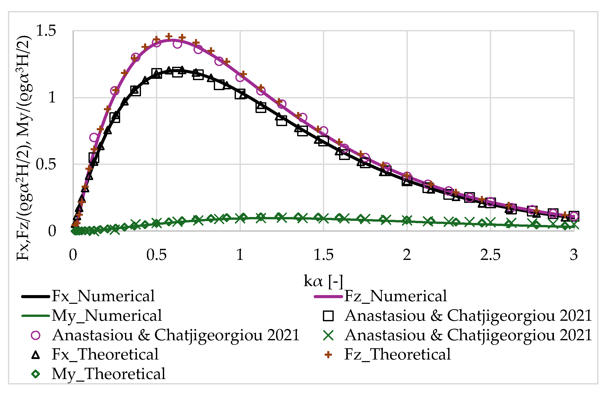
The examined oblate spheroid of a semi-axis α is subjected to an incident wave, at a water depth 20α. The body is fully submerged below the free water surface, and the distance between the spheroid’s center and the free surface is 1.5α. Also, the distance from the body’s center to the pole along its symmetry axis is α/1.25 (see Figure 2). The comparison is made in terms of the dimensionless exciting forces and moments (see Equations (28) and (29)), i.e., F x / ( ρ g a 2 H / 2 ) ,   F z / ( ρ g a 2 H / 2 ) , and M y / ( ρ g a 3 H / 2 ) , where ρ is the water density, g is the gravity acceleration, and H / 2 is the wave amplitude. The results are plotted against the dimensionless value of kα, where k is the wave number.
Figure 3 illustrates the horizontal and vertical exciting forces and horizontal moments on the oblate spheroid. An excellent correlation between the theoretical results (present formulation), the numerical outcomes (ANSYS AQWA), and those reported in [51] can be observed. Consequently, it may be inferred that the current theoretical model aptly simulates the hydrodynamic behavior of a submerged spheroid body under wave interactions.

3.2. Oblate Spheroid

Subsequently, an investigation is conducted on an oblate and a prolate spheroid under various levels of submergence. Initially, an oblate spheroid of a semi-axis α , and distance from the body’s center to pole along its symmetry axis c = α /4, is considered. Here, the water depth equals to d = 20 α . The body is assumed to be floating at h = α /10, α /5, α /2 and α below the free water surface (see Figure 4). In Appendix B, the dimensions of the coaxial ring elements for the oblate spheroid utilized in the theoretical formulation are presented.
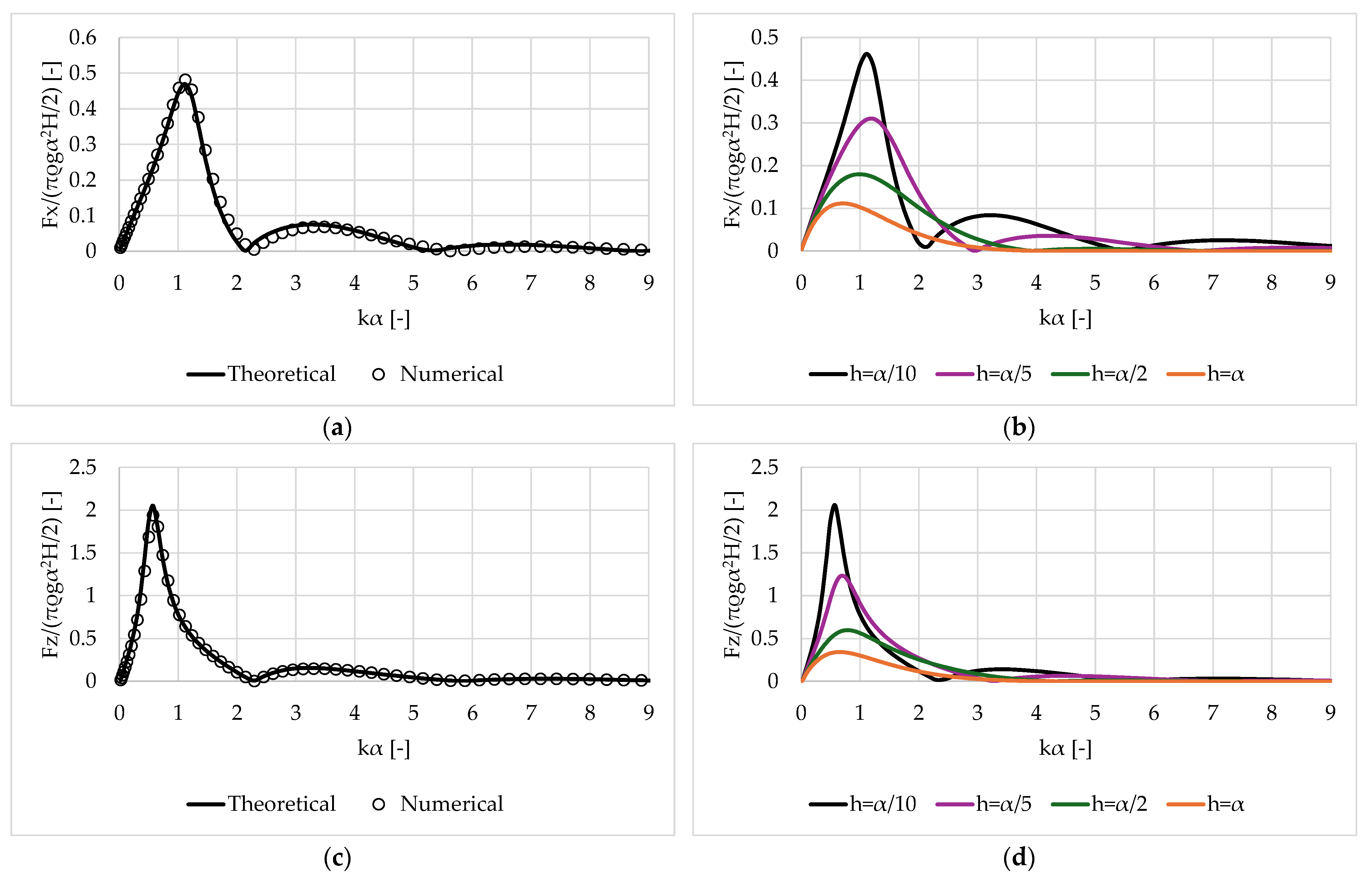
Figure 5, Figure 6 and Figure 7 present the hydrodynamic forces on the oblate spheroid evaluated by the aforementioned theoretical formulation, under various submergence values versus kα. Also, the AQWA software is applied for comparative purposes for the shallowest investigated submersion, i.e., h = α /10. Specifically, Figure 5 depicts the exciting forces and moments on the body for various considered submergences. Here, the results are non-dimensionalized by the term ( π ρ g a 2 H / 2 ) for the forces, and ( π ρ g a 3 H / 2 ) for the moments. It is evident that the employed methodology involving the division of the flow field surrounding the submerged body into coaxial ring-shaped fluid regions yields precise results in terms of the exciting forces and moments on the body. The theoretical predictions align with the numerical findings from AQWA (see Figure 5a,c,e). As far as the influence of the submergence value is concerned, it is apparent that both the forces and moments exhibit a progressive increase up to a maximum occurring at a relatively small wave frequency, followed by a subsequent decrease to zero. For greater submergence depths, the maxima of the surge and heave exciting forces shift towards lower frequencies compared to the ones for shallower submergence values. Furthermore, the submergence parameter notably impacts the frequencies of the minimum loading components, as evidenced in Figure 5b,d,f. As the submergence value increases, the zeroing of the forces and moments is shifted towards higher wave frequencies. It should be noted that the moments delineated herein and in the subsequent section are assessed with respect to the water surface, whereas for the comparisons with AQWA, they have been assessed in relation to the body’s center of gravity. Concerning the magnitudes of the exciting forces and moments, it is demonstrated that a reduction in the distance between the free surface and the body leads to an increase in the exciting wave loads.
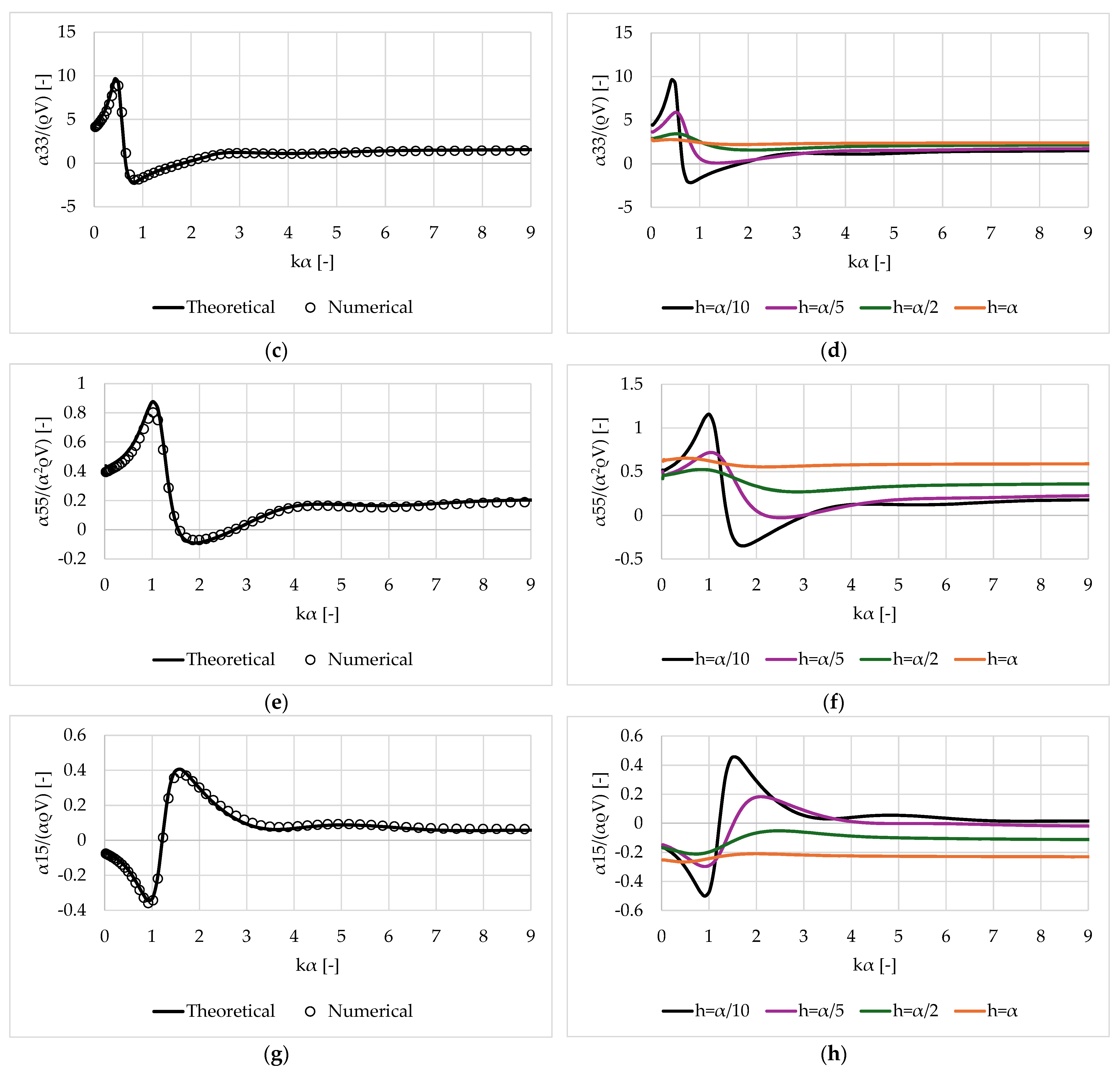
Figure 6 examines the hydrodynamic added mass coefficients of the immersed oblate spheroid in the surge, heave, pitch and surge-pitch directions. Here the results are normalized by the terms ( ρ V ) for the surge and heave, ( a 2 ρ V ) for the pitch, and ( a ρ V ) for the surge-pitch coeffients, respectively. Also, V denotes the submerged volume of the body. It is demonstrated that the hydrodynamic added mass coefficients can also be accurately evaluated utilizing the present theoretical formulation. The few attained discrepancies at a 11 / ( ρ V ) between the theoretical and numerical outcomes (see Figure 6a), in the viscinity of k a   ϵ   ( 1.5 , 4 ) , can be considered negligible. Conversely, it is immediately apparent that the comparisons of the heave, pitch and surge-pitch added mass coefficients, between the present method and AQWA, are quite favorable (Figure 6c,e,g). Further, the impact of the submergence value on the body’s hydrodynamic characteristics is presented in Figure 6b,d,f,h. Clearly, as the distance between the body and the free water surface decreases, the hydrodynamic coefficients attain a more tense oscillatory behavior. Specifically, for h = α /10, the surge, heave and pitch added mass, there is a sharp increase in their values, followed by an abrupt decrease to negative values. However, this is not the case for higher submergencies, i.e., h = α /5, α /2 and α , where a 11 / ( ρ V ), a 33 / ( ρ V ) and a 55 / ( α 2 ρ V ) generally attain positive values. In contrast, the surge-pitch added mass initially attains negative values, whereas as k a increases, and the submergence decreases, a 15 / ( a ρ V ) presents positive values. Furthermore, it can be noted that there is a smooth variation pattern of the body’s hydrodynamic coefficients for large submergence, i.e., h = α .
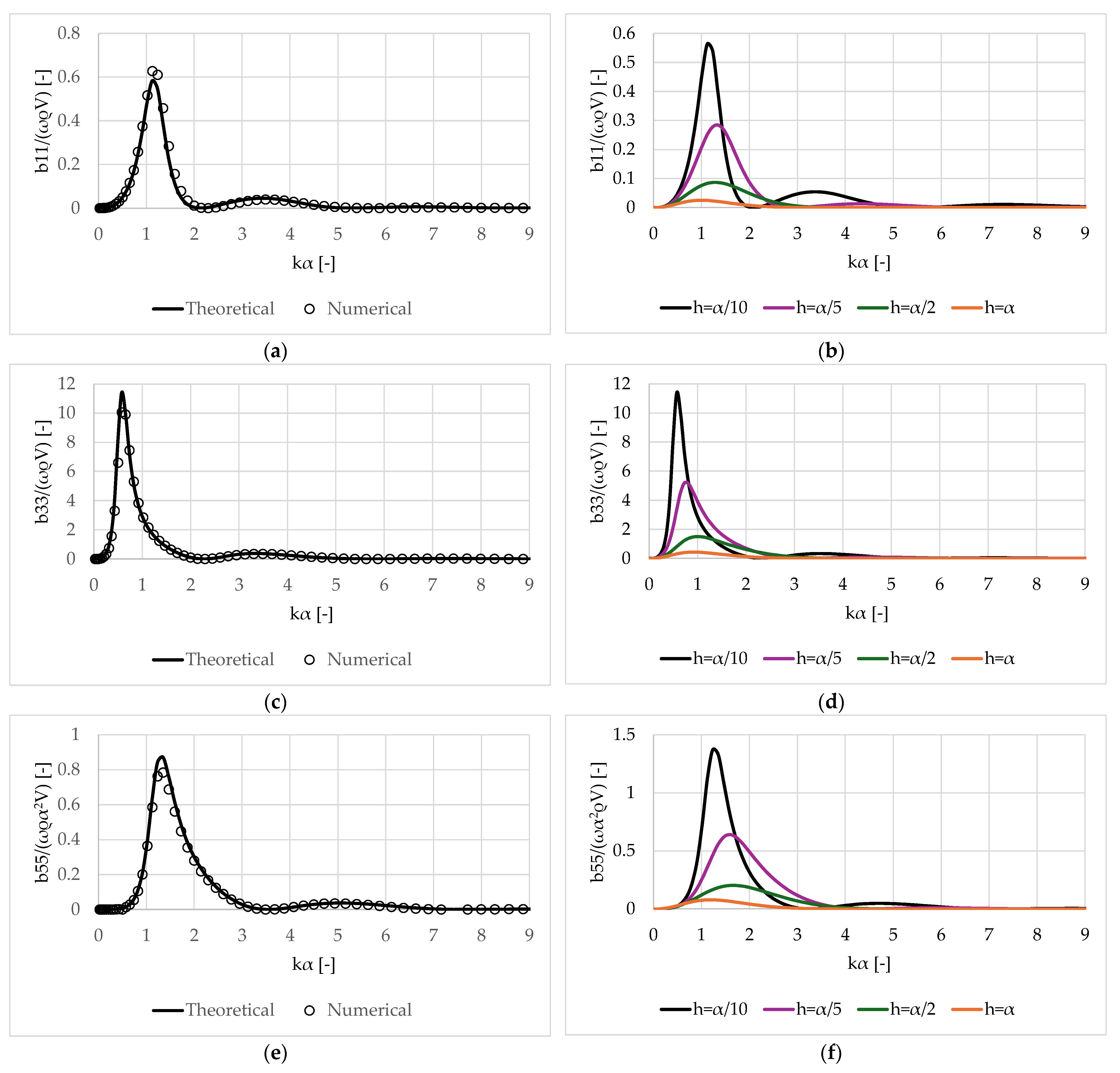
Figure 7 presents the hydrodynamic damping coefficients of the immersed oblate spheroid in the surge, heave, pitch and surge-pitch directions. Here, the results are normalized by the terms ( ω ρ V ) for the surge and heave, ( ω a 2 ρ V ) for the pitch, and ( ω a ρ V ) for the surge-pitch coefficients, respectively, where ω is the wave frequency. An excellent correlation between the theoretical and numerical results is evident (see Figure 7a,c,e,g). Consequently, the accuracy of the formulation remains unaltered. As far as the effect of the submergence values on the body’s hydrodynamic damping coefficients are concerned, it is apparent that the h value impacts the variation pattern of these coefficients. Specifically, as h decreases, the values of the damping term increase. In addition, a sharp increase in b i i , i = 1, 3, 5, followed by an intense decrease to zero is observed as the submergence value decreases. Nonetheless, this oscillatory behavior diminishes, and the wave frequency at which b i i , i = 1, 3, 5, zero, shifts towards higher ω with decreasing h values. On the contrary, the surge-pitch damping coefficient exhibits oscillatory behavior in the vicinity of negative values. These behaviors tend to subside as the submergence values increase, leading to a more gradual fluctuation pattern.

3.3. Prolate Spheroid

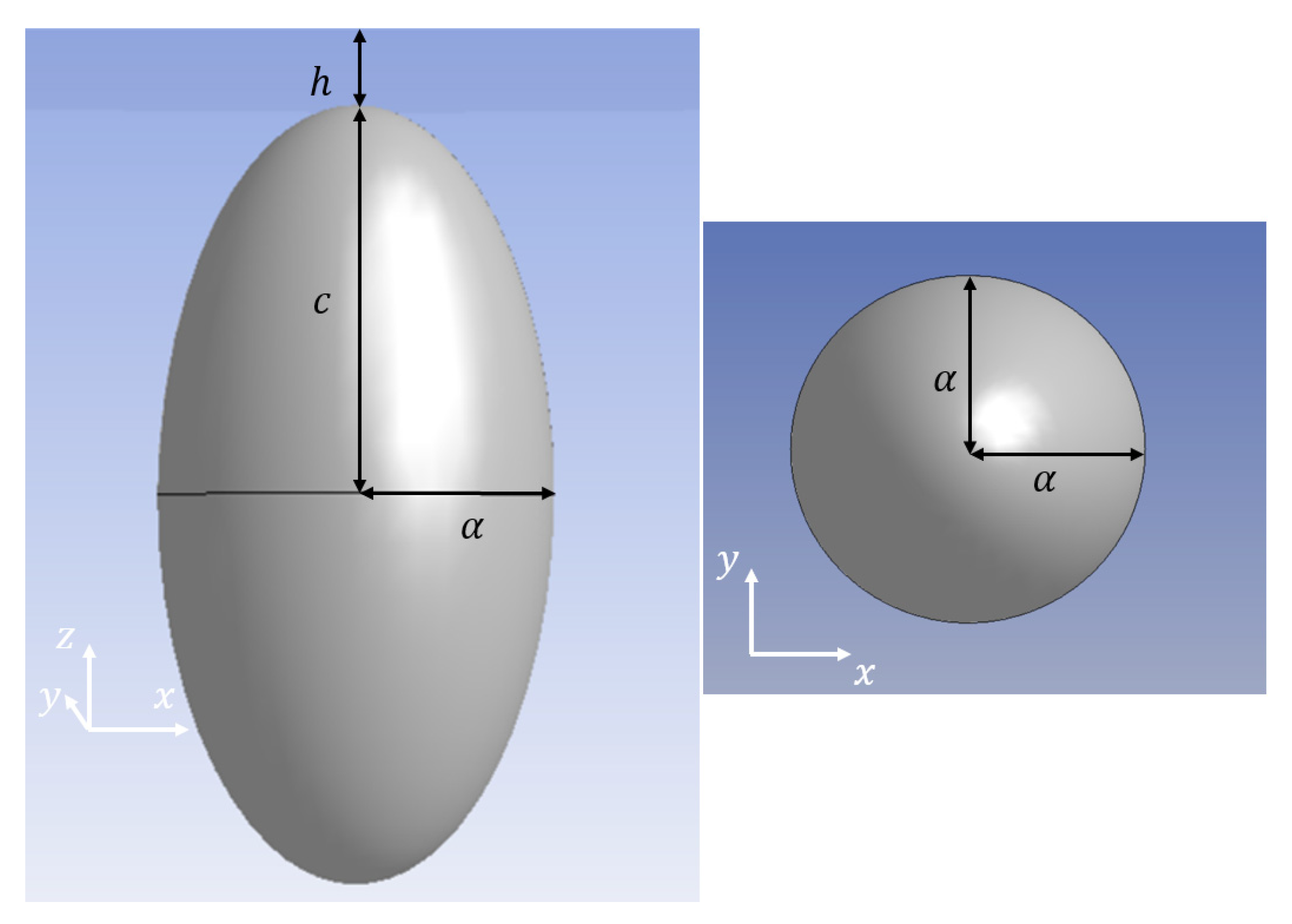
The methodology outlined herein can be effectively employed for a prolate spheroid under various levels of submergence. Specifically, a prolate spheroid of a semi-axis α , and distance from the body’s center to the pole along its symmetry axis c = 2 α , is considered. The water depth equals to d = 40 α , and the body is assumed to be floating at h = 2 a /10, 2 α /5, α , 2 α below the free water surface (see Figure 8). In Appendix B, the dimensions of the coaxial ring elements for the prolate spheroid utilized in the theoretical formulation are presented.
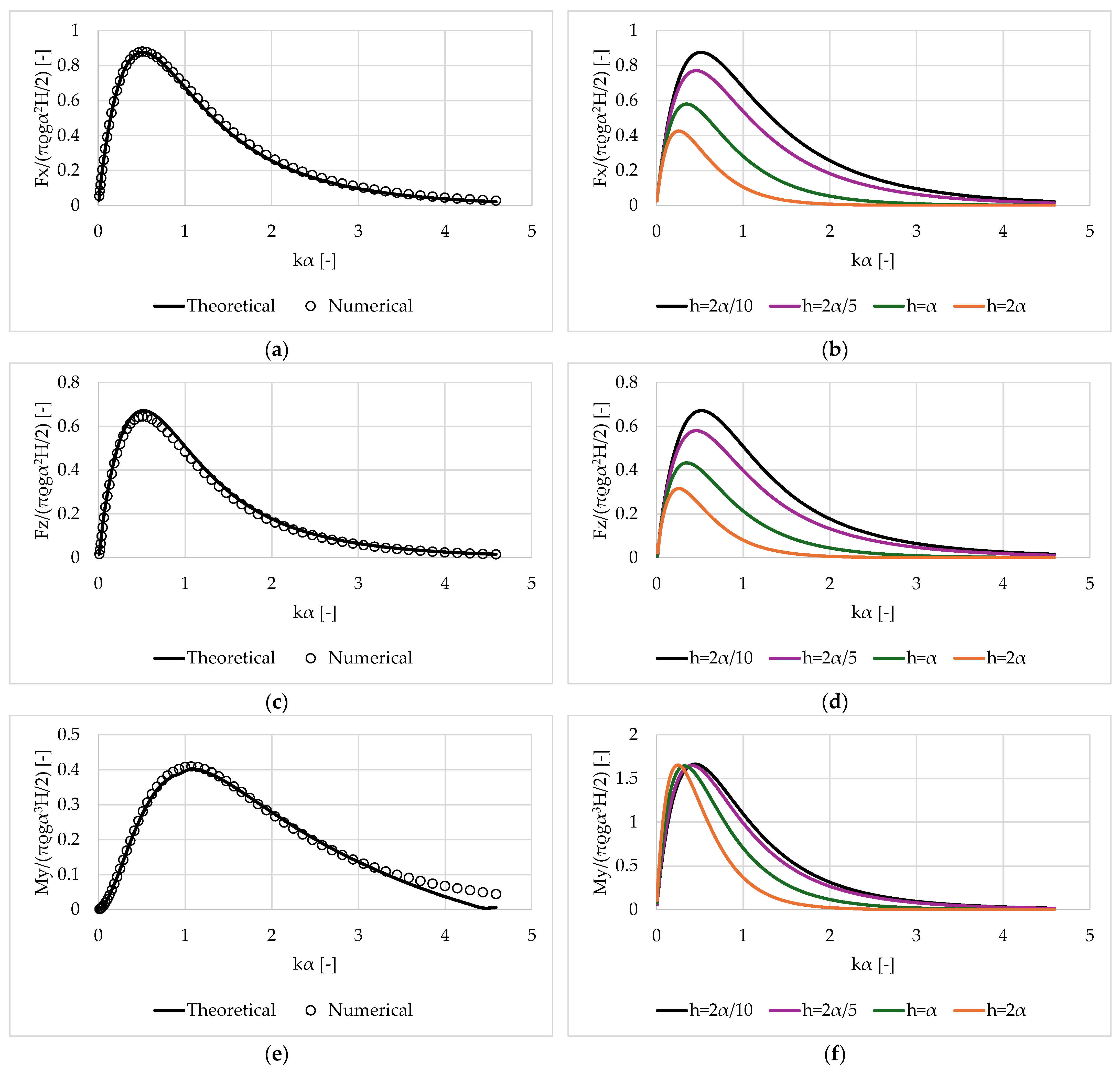
Figure 9, Figure 10 and Figure 11 present the hydrodynamic forces on the prolate spheroid evaluated by the presented theoretical formulation, under various submergence values versus kα. Also, the AQWA software is applied herein for comparative purposes for the shallowest investigated submersion, i.e., h = 2 α /10. Figure 9 depicts the dimensionless exciting forces and moments acting on the body. The normalized factor has been defined in Section 3.2. It is evident that the theoretical formulation adeptly captures the diffraction hydrodynamics of the prolate spheroid, as evidenced by the favorable comparisons with the AQWA outcomes (see Figure 9a,c,e). However, there are some discrepancies between the theoretical and numerical outcomes regarding the pitch moment at k a > 3.2 (see Figure 9e). Notably, this wave frequency surpasses the typical frequency bandwidth for gravity waves. Concerning the influence of the submergence values on the exciting forces and moments, a progressive increase in forces is observed, accompanied by a corresponding smooth decrease irrespective of the h value. Nevertheless, the upper bound of the forces attains higher values as h decreases. Also, the maximum of the exciting forces shifts to a smaller frequency as h increases. Noteworthy is the absence of a similar oscillatory pattern in the exciting forces as observed in an oblate spheroid (see Section 3.2). As far as the pitch exciting moment is concerned, Figure 9f reveals a similar fluctuation pattern across varying h values. Nevertheless, the wave frequency maximizing the acting moment shifts to lower values as h increases.
Figure 10 illustrates the hydrodynamic added mass coefficients of the immersed prolate spheroid in the surge, heave, pitch and surge-pitch directions. The results presented here are normalized using the same factor as detailed in Section 3.2. It is evident that while the theoretical formulation accurately predicts the surge hydrodynamic added mass coefficients (see Figure 10a), notable discrepancies arise when compared to AQWA results for the heave, pitch and surge-pitch added mass (Figure 10c,e,g). These discrepancies are more pronounced at higher values of k a . Such deviations between the theoretical and the numerical results can be attributed to the number of the considered fluid domains surrounding the body, which in this study amounts to 18 (i.e., 9 above the semi-axis α, and 9 below α). Regarding the effect of the submergence values on the hydrodynamic added mass of the spheroid, it is apparent that larger immersion depths result in a smoother variation in the added mass for both the surge and heave added mass. On the other hand, the pitch and surge-pitch added mass exhibit smooth fluctuations regardless of the h value. It is worthwhile to note that although the spheroid is submerged near the free surface, the surge, heave and pitch added mass consistently remain positive, without reaching negative values.
Figure 11 illustrates the hydrodynamic damping coefficients of the immersed prolate spheroid in the surge, heave, pitch and surge-pitch directions. These results are normalized by the factor previously mentioned (refer to Section 3.2). The theoretical formulation aligns well with the numerical outcomes, particularly noticeable in Figure 11a,c. However, some discrepancies are notable concerning the pitch and surge-pitch damping coefficients, which are more pronounced in the vicinity of k a 1 , 2 . Nevertheless, these can be considered negligible given that both methodologies exhibit a similar trend and variation pattern. As far as the influence of the submergence values on the body’s hydrodynamic damping coefficients are concerned, it is apparent that the h value impacts the variation pattern of these coefficients. Larger immersion depths result in a smoother variation in the damping coefficients. Also, it can be observed that as h increases, the wave frequencies at which the damping coefficients reach their maximum values shift to lower frequencies.

3.4. Vertical Cylinder

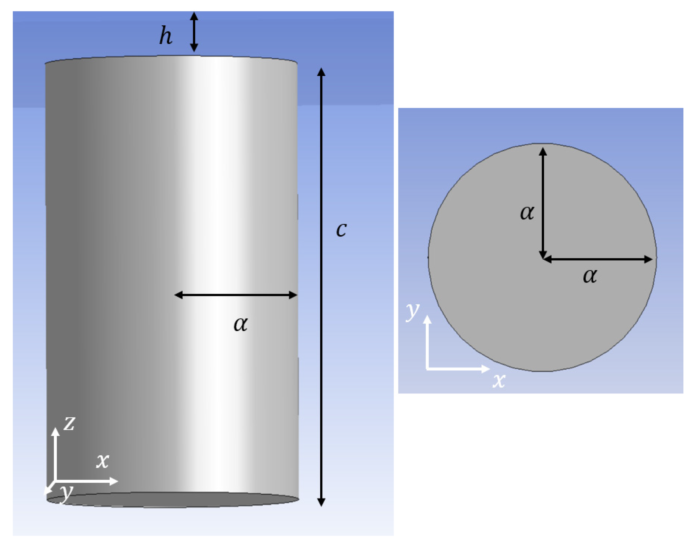
Based on the analysis, it has been concluded that negative added mass manifests in a submerged oblate spheroid body when floating near the free surface. Conversely, this phenomenon does not occur with a prolate spheroid of equivalent mass. Consequently, an investigation is undertaken to examine whether negative added mass is similarly observed in a fully submerged vertical cylinder, possessing the same mass as the aforementioned spheroids, when situated near the free surface. The objective is to examine the validity of this phenomenon in the context of the considered vertical cylinder characterized by a radius α, and a height c = 4.89 α . It is assumed that the water depth is 48.9 α and the distance between the free surface and the body’s upper surface is h = α /4.09 (see Figure 12). Figure 13 depicts the hydrodynamic coefficients of the cylinder, with Figure 13a,b presenting the surge, heave, pitch and surge-pitch hydrodynamic added mass and damping coefficients as functions of k a , respectively. These results are normalized by the factors previously mentioned (refer to Section 3.2).
It is evident from Figure 13 that despite the vertical cylinder possessing a mass equivalent to that of the two examine spheroids, and its height matching the vertical axis of the prolate spheroid, the heave added mass exhibits negative values in the vicinity of k a 1 , 2 . Conversely, the prolate spheroid demonstrates positive added mass values. Furthermore, the surge, pitch and surge-pitch added masses attain a similar oscillation pattern, consistently obtaining positive values across the entire k a spectrum (with the exception of the surge-pitch added mass, which attains negative values within the examined k a ). As for the surge, heave and pitch damping coefficients, these are always positive as in the spheroid cases, while the surge-pitch damping coefficients assume negative values within the examined k a range.

3.5. Sphere

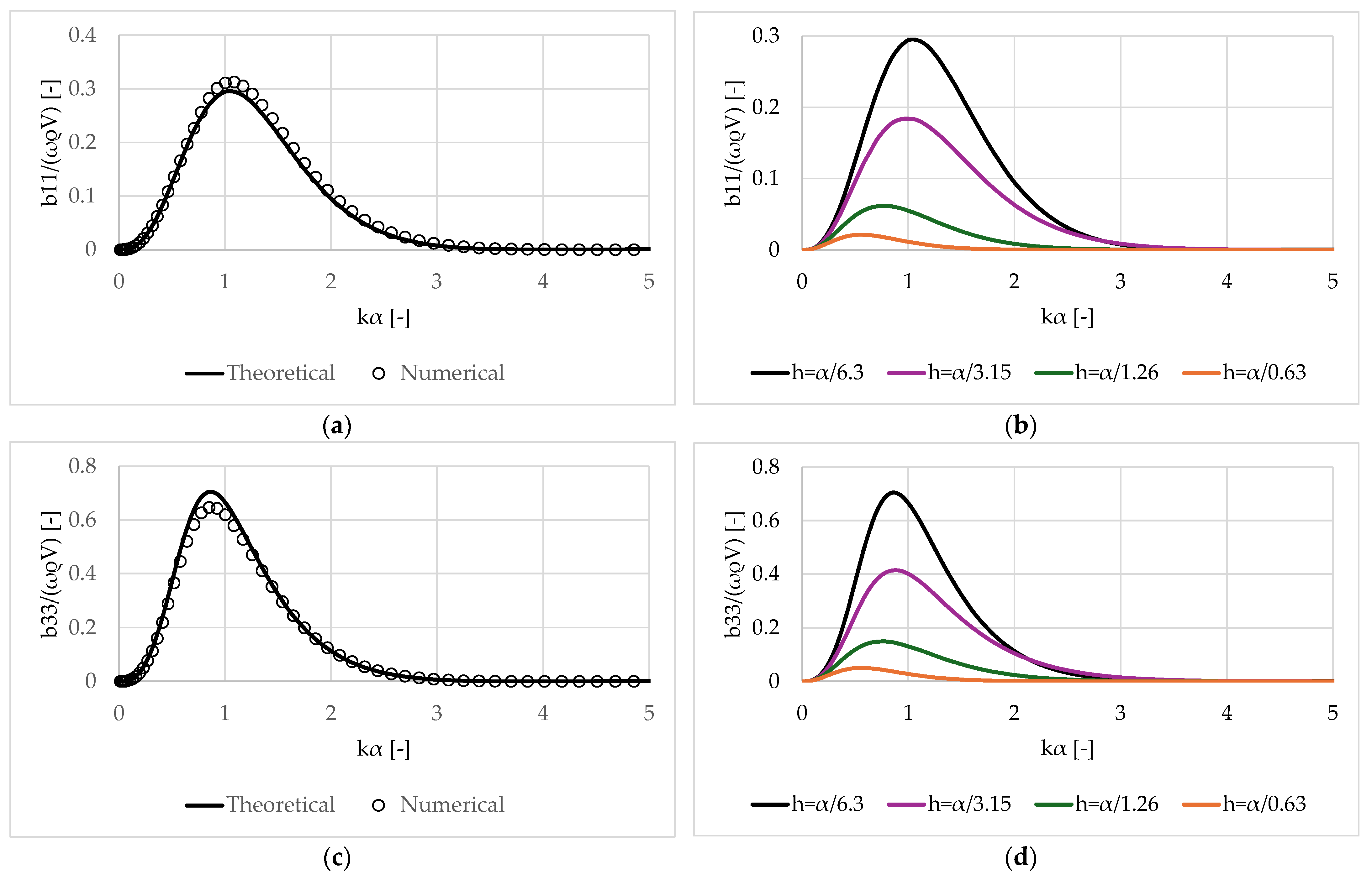
In the subsequent analysis, attention is directed towards the particular case of a spheroid characterized by equal semi-axes, effectively constituting a sphere. This sphere under examination shares the identical mass as the previously mentioned spheroids and possesses a radius denoted as α. The water depth equals to d = 31.75 α and the sphere is assumed to be floating at h = a /6.3, α /3.15, α / 1.26 , a / 0.63 , as illustrated in Figure 14. In Appendix B, the dimensions of the coaxial ring elements for the sphere utilized to the theoretical formulation are presented. Given that the exciting forces and moments on a submerged sphere have been presented in [54], and the theoretical approach has been validated against numerical formulations and high fidelity CFD simulations with very good correlation, further elaboration is omitted herein. Figure 15 and Figure 16 depict the hydrodynamic coefficients of the sphere (added mass and damping coefficients) normalized by the same parameters outlined in Section 3.2 for varying degrees of submersion. Here, the outcomes are derived by the theoretical formulation, whereas AQWA software is utilized for comparative purposes for a submergence h = a /6.3.
From Figure 15, it is evident that the added mass in both the surge and heave directions attains positive values for h = a /6.3, as well as for h = α /3.15, α / 1.26 , a / 0.63 . This trend was consistent for the prolate spheroid (refer to Section 3.3), whereas the oblate spheroid exhibited negative added mass values for the lowest considered submergence (refer to Section 3.2). Additionally, the vertical cylinder only demonstrated a negative added mass in the heave direction for the lowest submergence value (refer to Section 3.3). Regarding the comparisons between the theoretical and the numerical results, a very good agreement is evident. However, some discrepancies, particularly regarding the heave added mass coefficients (see Figure 16c), are observed, similar to those found for the prolate spheroid. As far as the influence of the submergence depth on the added mass is concerned, it can be seen that as the immerse depth decreases, a 11 ,   a 33 exhibit an oscillatory variation pattern.
Figure 16 illustrates the damping coefficients of the sphere in the surge and heave directions. A similar variation pattern to the aforementioned spheroids is observed. Specifically, it is evident that greater immersion depths result in a smoother variation in the damping coefficients, whereas as h increases, the wave frequencies at which the damping coefficients reach their maximum values shift to lower frequencies (see Figure 16b,d). Regarding the accuracy of the theoretical formulation, a very good correlation between theoretical and numerical outcomes can be observed. Consequently, the theoretical formulation can be confidently extended to a submerged sphere.
In regard to the number of region discretizations, the present work selects eight discretizations for the sphere for each of the I I and III fluid domains. Figure 17 depicts the hydrodynamic coefficients for a submergence depth of h = a / 6.3 , under four different values of region discretization for the upper and lower fluid domains, namely, 5, 8, 10 and 11. It can be observed that the number of region discretizations has a minor effect on the surge hydrodynamic coefficients. However, it affects the damping coefficients, particularly near peak frequencies, as well as the heave added mass across the entire wave frequency band. The latter appears to be principally affected by the number of region discretizations. Nevertheless, as the number of fluid regions increases, the values of the heave added mass converge.
Figure 18 presents the surge and heave added mass coefficients for the three examined bodies (i.e., oblate sphereoid, prolate spheroid, and sphere) for the same submergence depth of the three bodies consolidated into one diagram. The results are presented non-dimensionally as a function of the body’s volume, which remains constant, and are plotted as a function of kα. It is observed that the surge added mass of the prolate spheroid attains higher values compared to the other geometries examined. Regarding the heave added mass, the coefficient a 33 exhibit a more pronounced oscillatory behavior as the maximun radius of the body increases (this is the case of the oblate spheroid compared to its sphere and prolate spheroid equal-volumed counterparts).

4. Conclusions

In this work, an examination is conducted into the influence of submergence on the hydrodynamics of a spheroid body possessing constant mass, namely, oblate, prolate and spherical shapes, while floating beneath the free water surface. The investigation employs a theoretical formulation, with its accuracy assessed against numerical results obtained from ANSYS AQWA software. The principal conclusions derived from this study are outlined as follows:
  • The hydrodynamics of submerged bodies undergo significant alteration depending on their depth below the free water surface. Notably, when the distance between the body and the free water surface is minimal, pronounced peaks in the body’s hydrodynamics are observed.
  • Negative added mass coefficients manifest at specific wave frequencies and for shallow submergence depths. However, this trend diminishes as the distance between the body and the free surface increases. Nonetheless, damping coefficients consistently exhibit positive values across the examined frequency range, regardless of the submergence depth.
  • Oblate spheroids exhibit negative added mass coefficients in the surge, heave and pitch directions at the lowest examined submergence depth, while prolate spheroids demonstrate positive added mass coefficients in these directions. Similarly, the examined sphere exhibits positive added mass coefficients in the surge and heave directions. Conversely, cylinders only exhibit negative added mass coefficients in the heave direction.
  • With respect to the methodologies employed, the results derived from the developed theoretical formulation closely align with the variation pattern observed from the numerical method outcomes. However, deviations are evident at wave frequencies corresponding to peaks in the body’s hydrodynamics. Furthermore, it is pertinent to note that the present formulation is not applicable to ellipsoid-shaped bodies.
  • The analysis findings indicate that in near-surface operations (i.e., for submergence depths less than the radius of the submerged body), wave motion primarily comprises a standing wave, resulting in rapid fluctuations in both added mass and damping coefficients. Hence, when designing submerged bodies, meticulous consideration of the geometric attributes in relation to the wave characteristics is imperative, as unexpected forces on the hull may arise, augmenting the body’s inertia and influencing its acceleration.

Author Contributions

Conceptualization, A.S.M. and D.N.K.; methodology, A.S.M. and D.N.K.; software, S.A.M.; validation, S.A.M. and D.N.K.; formal analysis, A.S.M.; investigation, A.S.M. and D.N.K.; writing—original draft preparation, D.N.K.; writing—review and editing, S.A.M. and A.S.M.; visualization, D.N.K. and A.S.M.; supervision, S.A.M. All authors have read and agreed to the published version of the manuscript.

Funding

This research received no external funding.

Institutional Review Board Statement

Not applicable.

Informed Consent Statement

Not applicable.

Data Availability Statement

The data supporting the reported results can be provided to the reader upon reasonable request.

Conflicts of Interest

The authors declare no conflicts of interest.

Appendix A

In the sequel, suitable series representations of the functions Ψ j m l ,   j = D , 1 ,   3 ,   5 ;   l = I , III are presented.
For the outer fluid domain I ( r a ,   0 z d ), it holds:
1 δ j Ψ j m I r , z = g j m I r , z + n = 0 F j , m n I K m a n r K m a n a Z n I z ,   for   j = D , 1 , 3 , 5
In Equation (A1), the term g j m I equals to:
g D m I r , z = J m k r J m k a H m k a H m k r Z 0 z d Z ´ 0 d g 11 I r , z = g 30 I r , z = g 51 I r , z = 0
Here, H m is the m-th order Hankel function of the first kind, and Z n are orthonormal functions in [ 0 , d ], which are defined as:
Z n I z = 1 2 1 + s i n h ( 2 k d ) 2 k d 1 / 2 c o s h ( k z ) Z n I z = 1 2 1 + sin ( 2 a n d ) 2 a n d 1 / 2 c o s ( a n z )
The terms a n denote the number of roots of the transcendental Equation (24), whilst the functions K m and δ j have been introduced in Equations (21) and (23), respectively.
For the lower fluid domain III
1 δ j Ψ j m I I I r , z = g j m I I I r , z + n q = 0 ε n q [ R m n q r F j , m n q I I I + R m n q * r F j , m n q * I I I ] c o s n q π z h q ,   f o r   a q r a q + 1 ,   0 z h q ,   q = 1 , 2 , , Q
where:
g D m I I I r , z = g 11 I I I r , z = 0 ;   g 30 I I I r , z = z 2 1 2 r 2 2 h q d ;   g 51 I I I r , z = r z 2 1 4 r 2 2 h q d 2
And
R m n q = K m n q π a q h q I m n q π r h q K m n q π r h q I m n q π a q h q I m n q π a q + 1 h q K m n q π a q h q I m n q π a q h q K m n q π a q + 1 h q ,   m , n q 0 ;   R m n q = r a q m a q r m a q + 1 a q m a q a q + 1 m ,   n q = 0 ,   m 0 ;   R 00 I I = ln r a q ln a q + 1 a q ,   n q , m = 0
R m n q * = K m n q π r h q I m n q π a q + 1 h 2 K m n q π a q + 1 h q I m n q π r h q I m n q π a q + 1 h q K m n q π a q h q I m n q π a q h q K m n q π a q + 1 h q ,   m , n q 0 ;   R m n q * = a q + 1 r m r a q + 1 m a q + 1 a q m a q a q + 1 m ,   n q = 0 ,   m 0 ;   R 00 * I I = ln a q + 1 r ln a q + 1 a q ,   n q , m = 0
For the lower cylindrical region, Equation (A4) can be rewritten as:
1 δ j Ψ j m I I I r , z = g j m I I I r , z + n q = 0 ε n q F j , m n q I I I I m n q π r h 0 I m n q π a 0 h 0 c o s n p π z h 0
The functions g j m I I I are derived from Equation (A5).
In Equations (A4) and (A8), ε n p is the Newmann’s symbol, whereas F j , m n p I I I , F j , m n q * I I I are the unknown Fourier coefficients to be determined through the solution process.

Appendix B

In Table A1, Table A2 and Table A3, the dimensions of the coaxial ring elements for the fully submerged bodies are presented.
Table A1. Oblate spheroid for h = α /10.
RadiiDistance from the Seabed
a 0 0.108 α d d 0 19.90α h 0 19.40α
a 1 0.500 α d d 1 19.83α h 1 19.42α
a 2 0.866 α d d 2 19.82α h 2 19.47α
a 3 α d d 3 19.73α h 3 19.56α
Table A2. Prolate spheroid for h = 2 a /10.
RadiiDistance from the Seabed
a 0 0.015 α d d 0 39.80α h 0 35.80α
a 1 0.195 α d d 1 39.78α h 1 35.82α
a 2 0.382 α d d 2 39.70α h 2 35.89α
a 3 0.555 α d d 3 39.55α h 3 36.04α
a 4 0.707 α d d 4 39.34α h 4 36.25α
a 5 0.831 α d d 5 39.06α h 5 36.53α
a 6 0.923 α d d 6 38.75α h 6 36.85α
a 7 0.981 α d d 7 38.39α h 7 37.20α
a 8 α d d 8 38.06α h 8 37.54α
Table A3. Sphere for h = a /6.3.
RadiiDistance from the Seabed
a 0 0.015 α d d 0 31.58α h 0 29.58α
a 1 0.195 α d d 1 31.57α h 1 29.59α
a 2 0.382 α d d 2 31.54α h 2 29.63α
a 3 0.555 α d d 3 31.46α h 3 29.71α
a 4 0.707 α d d 4 31.35α h 4 29.81α
a 5 0.831 α d d 5 31.22α h 5 29.95α
a 6 0.923 α d d 6 31.06α h 6 30.11α
a 7 0.981 α d d 7 30.88α h 7 30.29α
a 8 α d d 8 30.72α h 8 30.45α

References

  1. Ogilvie, T.F. First- and second-order forces on a cylinder submerged under a free surface. J. Fluid Mech. 1963, 163, 451–472. [Google Scholar] [CrossRef]
  2. Chung, J.S. Forces on submerged cylinders oscillating near free surface. J. Hydronautics 1977, 11, 100–106. [Google Scholar] [CrossRef]
  3. Newman, J.N.; Sortland, B.; Vinje, T. Added mass and damping of rectangular bodies close to the free surface. J. Ship Res. 1984, 28, 219–225 . [Google Scholar] [CrossRef]
  4. McIver, P.; Evans, D.V. The occurrence of negative added mass in free-surface problems involving submerged oscillating bodies. J. Eng. Math. 1984, 18, 7–22. [Google Scholar] [CrossRef]
  5. Falnes, J.; McIver, P. Surface wave interactions with systems of oscillating bodies and pressure distributions. Appl. Ocean Res. 1985, 7, 225–234. [Google Scholar] [CrossRef]
  6. Greenhow, M.; Ahn, S.I. Added mass and damping of horizontal circular cylinder sections. Ocean Eng. 1988, 15, 495–504. [Google Scholar] [CrossRef]
  7. Newman, J.N. The motions of a floating slender torus. J. Fluid Mech. 1977, 83, 721–735. [Google Scholar] [CrossRef]
  8. McIver, P.; McIver, M. Trapped modes in an axisymmetric water-wave problem. Q. J. Mech. Appl. Math. 1977, 50, 165–178. [Google Scholar] [CrossRef]
  9. McIver, P.; McIver, M. Motion trapping structures in the three-dimensional water-wave problem. In Proceedings of the 21st International Workshop on Water Waves and Floating Bodies, Loughborough, UK, 2–5 April 2006. [Google Scholar]
  10. Newman, J.N. Radiation and diffraction analysis of the McIver toroid. J. Eng. Math. 1999, 35, 135–147. [Google Scholar] [CrossRef]
  11. McIver, P.; Newman, J.N. Trapping structures in the three-dimensional water-wave problem. J. Fluid Mech. 2003, 484, 283–301. [Google Scholar] [CrossRef]
  12. Mavrakos, S.A. Hydrodynamic characteristics for groups of interacting axisymmetric bodies submerged near the sea surface of the sea bed. In Proceedings of the 3rd International Offshore and Polar Engineering Conference, Singapore, 6–11 June 1993. [Google Scholar]
  13. Shao, Z.; Chen, Y.; Fang, D.; Feng, S. Fuzzy depth control of small cylinder object navigating near free-surface. Appl. Mech. Mater. 2012, 128, 886–889. [Google Scholar] [CrossRef]
  14. Teng, B.; Li, Z.; Cong, L.; Sheng, J. Generalized hydrodynamic coefficients of twin connected circular cylinders in finite water depth. Ocean Eng. 2023, 289, 116263. [Google Scholar] [CrossRef]
  15. Michell, J.H. The wave-resistance of a ship. Lond. Edinb. Dublin Philos. Mag. J. Sci. 1898, 45, 106–123. [Google Scholar] [CrossRef]
  16. Havelock, T.H. Some cases of wave motion due to a submerged obstacle. In Proceedings of the Royal Society A 93, 1 September 1917; pp. 520–532. [Google Scholar] [CrossRef]
  17. Havelock, T.H. The wave resistance of a spheroid. In Proceedings of the Royal Society A 131, 1 May 1931; pp. 275–285. [Google Scholar] [CrossRef]
  18. Chepelianskii, A.; Schindler, M.; Chevy, F.; Raphael, E. Self-consistent theory of capillary–gravity-wave generation by small moving objects. Phys. Rev. E 2010, 81, 016306. [Google Scholar] [CrossRef] [PubMed]
  19. Benusiglio, A.; Chevy, F.; Raphael, E.; Clanet, C. Wave drag on a submerged sphere. Phys. Fluids 2015, 27, 07210. [Google Scholar] [CrossRef]
  20. Sergiienko, N.; Cazzolato, B.S.; Ding, B.; Hardy, P.; Arjomandi, M. Performance comparison of the floating and fully submerged quasi-point absorber wave energy converters. Renew Energy 2017, 108, 425–437. [Google Scholar] [CrossRef]
  21. Mc Cauley, G.J. Exploring Simplified Models for Wave Interaction with a Shallowly Submerged Structures with Application to Ocean Wave Energy. Ph.D. Thesis, University of Western Australia, Crawley, WA, Australia, 2021. [Google Scholar]
  22. Mc Cauley, G.J.; Wolgamot, H.; Orszaghova, J.; Draper, S. Linear hydrodynamic modelling of arrays of submerged oscillating cylinders. Appl. Ocean Res. 2018, 81, 1–14. [Google Scholar] [CrossRef]
  23. Arentzen, E.S.; Mandel, P. Naval architectural aspects of submarine design. Soc. Nav. Archit. Mar. Eng. 1960, 68, 622–692. [Google Scholar]
  24. Burcher, R.; Rydill, L.J. Concepts in Submarine Design; Ocean Technology Series 2; Cambridge University Press: Cambridge, UK, 1994. [Google Scholar] [CrossRef]
  25. Jagadeesh, P.; Murali, K.; Idichandy, V.G. Experimental investigation of hydrodynamic force coefficients over AUV hull form. Ocean Eng. 2009, 36, 113–118. [Google Scholar] [CrossRef]
  26. Mansoorzadeh, S.; Javanmard, E. An investigation of free surface effects on drag and lift coefficients of an autonomous underwater vehicle (AUV) using computational and experimental fluid dynamics methods. J. Fluids Struct. 2014, 51, 161–171. [Google Scholar] [CrossRef]
  27. Nematollahi, A.; Dadvand, A.; Dawoodian, M. An axisymmetric underwater vehicle-free surface interaction: A numerical study. Ocean Eng. 2015, 96, 205–214. [Google Scholar] [CrossRef]
  28. Conway, A.S.T.; Valentinis, F.; Seil, G. Characterization of suction effects on a submarine body operating near the free surface. In Proceedings of the 21st Australian Fluid Mechanics Conference, Adelaide, Australia, 10–13 November 2018. [Google Scholar]
  29. Amiri, M.M.; Esperana, P.; Vitola, M.A.; Sphaier, S.H. How does the free surface affect the hydrodynamics of a shallowly submerged submarine? Appl. Ocean Res. 2018, 76, 34–50. [Google Scholar] [CrossRef]
  30. Amiri, M.M.; Esperana, P.; Vitola, M.A.; Sphaier, S.H. An initial evaluation of the free surface effect on the maneuverability of underwater vehicles. Ocean Eng. 2019, 196, 106851. [Google Scholar] [CrossRef]
  31. Amiri, M.M.; Esperana, P.; Vitola, M.A.; Sphaier, S.H. Investigation into the wave system of a generic submarine moving along a straight path beneath the free surface. Eur. J. Mech. –B/Fluids 2019, 76, 98–114. [Google Scholar] [CrossRef]
  32. Amiri, M.M.; Esperana, P.; Vitola, M.A.; Sphaier, S.H. Viscosity effect on an underwater vehicle-free surface hydrodynamic interaction. Appl. Ocean Res. 2020, 104, 102365. [Google Scholar] [CrossRef]
  33. Lambert, W.; Brizzolara, S. On the effect of non-linear boundary conditions on the wave disturbance and hydrodynamic forces of underwater vehicles travelling near the free-surface. In Proceedings of the 39th International Conference on Ocean, Offshore and Arctic Engineering, The American Society of Mechanical Engineers, Fort Lauderdale, FL, USA, 3–7 August 2020. [Google Scholar]
  34. Sudharsun, G.; Ali, A.; Mitra, A.; Jaiswal, A.; Naresh, P.; Warrior, H.V. Free surface features of submarines moving underwater: Study of Bernoulli Hump. Ocean Eng. 2022, 249, 110792. [Google Scholar] [CrossRef]
  35. Ling, X.; Leong, Z.Q.; Duffy, J. Effects of pitch angle on a near free surface underwater vehicle. Ocean Eng. 2023, 286, 115611. [Google Scholar] [CrossRef]
  36. Hao, Y.; Shen, D.; Xiong, Z. Design of submarine near-surface depth controller. In Proceedings of the 5th World Congress on Intelligent Control and Automation, Hangzhou, China, 15–19 June 2004. [Google Scholar] [CrossRef]
  37. Choi, J.H.; Yeo, D.J.; Rhee, K.P.; Park, J.Y. On the vertical plane dynamics modeling and depth control of a submerged body moving beneath free surface. J. Soc. Nav. Archit. Korea 2006, 43, 647–655. [Google Scholar] [CrossRef]
  38. Choi, J.H.; Rhee, K.P.; Ann, S.P.; Lee, S.K. Mathematical model of wave forces and moments for the depth control of a submerged body. In Proceedings of the Annual Spring Meeting of the Society of Naval Architects of Korea, Jeju, Korea, 29–30 May 2008; pp. 1228–1235. [Google Scholar]
  39. Ananthakrishman, P. AUV Hydrodynamics in Shallow Water During Adverse Weather Conditions; Defense Technical Information Center, US Government, USA, 1999.
  40. Rezazadegan, F.; Shojaei, K.; Sheikholeslam, F.; Chatraei, A. A novel approach to 6-DOF adaptive trajectory tracking control of an AUV in the presence of parameter uncertainties. Ocean Eng. 2015, 107, 246–258. [Google Scholar] [CrossRef]
  41. Park, J.Y.; Kim, N.; Yoon, H.K.; Cho, H. Adaptive depth controller design for a submerged body moving near free surface. Appl. Ocean Res. 2016, 58, 83–94. [Google Scholar] [CrossRef]
  42. Youn, T.G.; Kim, M.J.; Kim, M.C.; Kang, J.G. Effect of free surface based on submergence depth of underwater vehicle. J. Ocean Eng. Technol. 2022, 36, 83–90. [Google Scholar] [CrossRef]
  43. Zemlyak, V.; Pogorelova, A.; Kozin, V. Motion of a submerged body in a near-surface water environment. Int. J. Nav. Archit. Ocean Eng. 2022, 14, 100433. [Google Scholar] [CrossRef]
  44. Zemlyak, V.; Pogorelova, A.; Kozin, V. Motion of a submerged body under a free surface and an ice cover in finite water depth conditions. Ocean Eng. 2023, 288, 116161. [Google Scholar] [CrossRef]
  45. Kokkinowrachos, K.; Mavrakos, S.; Asorakos, S. Behavior of vertical bodies of revolution in waves. Ocean Eng. 1986, 13, 505–538. [Google Scholar] [CrossRef]
  46. Mavrakos, S.A. Wave loads on a stationary floating bottomless cylinder with finite wall thickness. Appl. Ocean Res. 1985, 7, 213–224. [Google Scholar] [CrossRef]
  47. Mavrakos, S.A. Hydrodynamic coefficients in heave of two concentric surface-piercing truncated circular cylinders. Appl. Ocean Res. 2004, 26, 84–97. [Google Scholar] [CrossRef]
  48. Konispoliatis, D.N.; Chatjigeorgiou, I.K.; Mavrakos, S.A. Theoretical hydrodynamic analysis of a surface-piercing porous cylindrical body. Fluids 2021, 6, 320. [Google Scholar] [CrossRef]
  49. Abramowitz, M.; Stegun, I. Handbook of Mathematical Functions; Dover Publications, Inc.: New York, NY, USA, 1970. [Google Scholar]
  50. Newman, J.N. Marine Hydrodynamics; MIT Press: Cambridge, MA, USA, 1977. [Google Scholar]
  51. Anastasiou, E.I.; Chatjigeorgiou, I.K. Hydrodynamics of a submerged oblate spheroid in finite water depth using the method of ultimate image singularities. Appl. Ocean Res. 2021, 111, 102636. [Google Scholar] [CrossRef]
  52. ANSYS AQWA Theory Manual; ANSYS Inc.: Canonsburg, PA, USA, 2015.
  53. Mavrakos, S.A. Users manual for the software HAMVAB. School of Naval Architecture and Marine Engineering, Laboratory for Floating Structures and Mooring Systems, National Technical University edition. Athens, Greece, 1995. [Google Scholar]
  54. Mavrakos, S.A.; Zafeiris, S.; Papadakis, G.P.; Konispoliatis, D.N. Semi-analytical and CFD formulations of a spherical floater. In Proceedings of the 15th European Wave and Tidal Conference (EWTEC), Bilbao, Spain, 3–7 September 2023. [Google Scholar]
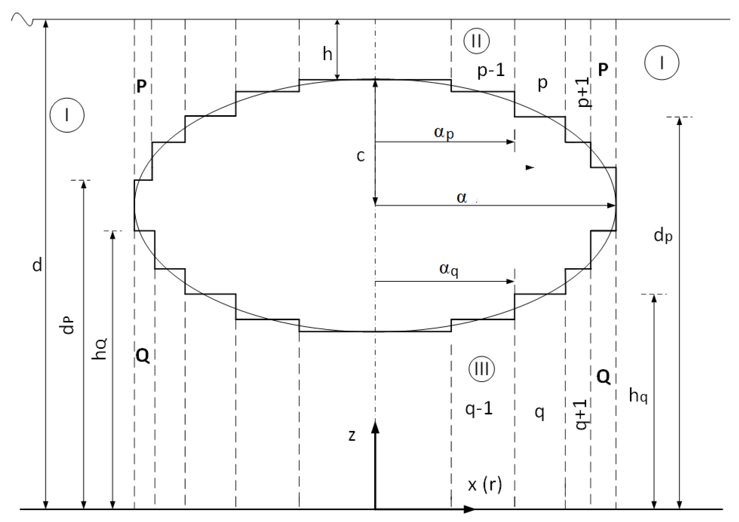
Figure 1. Discretization of the flow field around the considered submerged body with vertical axis of symmetry.
Jmse 12 00893 g001
Figure 2. 2D representation of the examined oblate spheroid (left image); 3D image of an axisymmetric oblate spheroid from AQWA (center image); 3D image of an axisymmetric oblate spheroid using the discretization of the flow field into coaxial ring-shaped fluid regions (right image).
Jmse 12 00893 g002
Figure 3. Dimensionless exciting forces and moments on an oblate spheroid calculated by theoretical and numerical formulations. The results are also compared with the outcomes of [51].
Jmse 12 00893 g003
Figure 4. 3D representation (left figure) and plane view (right figure) of the examined oblate spheroid.
Jmse 12 00893 g004
Figure 5. Dimensionless exciting forces and moments on an oblate spheroid calculated by theoretical and numerical formulations: (a,c,e) Dimensionless surge, heave force and pitch moment at the shallowest investigated submersion, h = α /10, respectively. The results are compared with the outcomes from AQWA; (b,d,f) Dimensionless surge, heave force and pitch moment at various levels of submergence h = α /10, α /5, α /2, α .
Jmse 12 00893 g005aJmse 12 00893 g005b
Figure 6. Dimensionless hydrodynamic added mass coefficient of an oblate spheroid calculated by theoretical and numerical formulations: (a,c,e,g) Dimensionless surge, α 11 , heave, α 33 , pitch, α 55 , and surge-pitch, α 15 , added mass coefficient at the shallowest investigated submersion, h = α /10. The results are compared with the outcomes from AQWA; (b,d,f,h) Dimensionless α 11 , α 33 , α 55 , and α 15 at various levels of submergence h = α /10, α /5, α /2, α .
Jmse 12 00893 g006aJmse 12 00893 g006b
Figure 7. Dimensionless hydrodynamic damping coefficient of an oblate spheroid calculated by theoretical and numerical formulations: (a,c,e,g) Dimensionless surge, b 11 , heave, b 33 , pitch, b 55 , and surge-pitch, b 15 , damping coefficient at the shallowest investigated submersion, h = α /10. The results are compared with the outcomes from AQWA; (b,d,f,h) Dimensionless b 11 , b 33 , b 55 , and b 15 at various levels of submergence h = α /10, α /5, α /2, α .
Jmse 12 00893 g007aJmse 12 00893 g007b
Figure 8. 3D representation (left figure) and plane view (right figure) of the examined prolate spheroid.
Jmse 12 00893 g008
Figure 9. Dimensionless exciting forces and moments on a prolate spheroid calculated by theoretical and numerical formulations: (a,c,e) Dimensionless surge, heave force and pitch moment at the shallowest investigated submersion, h = 2 α /10, respectively. The results are compared with the outcomes from AQWA; (b,d,f) Dimensionless surge, heave force and pitch moment at various levels of submergence h = 2 α /10, 2 α /5, α , 2 α .
Jmse 12 00893 g009
Figure 10. Dimensionless hydrodynamic added mass coefficient of a prolate spheroid calculated by theoretical and numerical formulations: (a,c,e,g) Dimensionless surge, α 11 , heave, α 33 , pitch, α 55 , and surge-pitch, α 15 , added mass coefficient at the shallowest investigated submersion, h = 2 α /10. The results are compared with the outcomes from AQWA; (b,d,f,h) Dimensionless α 11 , α 33 , α 55 , and α 15 at various levels of submergence h = 2 α /10, 2 α /5, α , 2 α .
Jmse 12 00893 g010aJmse 12 00893 g010b
Figure 11. Dimensionless hydrodynamic damping coefficient of a prolate spheroid calculated by theoretical and numerical formulations: (a,c,e,g) Dimensionless surge, b 11 , heave, b 33 , pitch, b 55 , and surge-pitch, b 15 , damping coefficient at the shallowest investigated submersion, h = 2 α /10. The results are compared with the outcomes from AQWA; (b,d,f,h) Dimensionless b 11 , b 33 , b 55 , and b 15 at various levels of submergence h = 2 α /10, 2 α /5, α , 2 α .
Jmse 12 00893 g011
Figure 12. 3D representation (left figure) and plane view (right figure) of the examined vertical cylinder.
Jmse 12 00893 g012
Figure 13. Dimensionless hydrodynamic coefficients of a vertical cylinder: (a) Dimensionless surge, a 11 , heave, a 33 , pitch, a 55 , and surge-pitch, a 15 , added mass coefficient; (b) Dimensionless b 11 , b 33 , b 55 , and b 15 for h = α /4.09.
Jmse 12 00893 g013
Figure 14. 3D representation of the examined sphere.
Jmse 12 00893 g014
Figure 15. Dimensionless hydrodynamic added mass coefficient of a sphere calculated by theoretical and numerical formulations: (a,c), Dimensionless surge, α 11 , and heave, α 33 , added mass coefficient at the shallowest investigated submersion, h = a /6.3. The results are compared with the outcomes from AQWA; (b,d), Dimensionless α 11 , α 33 , at various levels of submergence h = a /6.3, α /3.15, α / 1.26 , a / 0.63 .
Jmse 12 00893 g015aJmse 12 00893 g015b
Figure 16. Dimensionless hydrodynamic damping coefficient of a sphere calculated by theoretical and numerical formulations: (a,c), Dimensionless surge, b 11 , and heave, b 33 , damping coefficient at the shallowest investigated submersion, h = a /6.3. The results are compared with the outcomes from AQWA; (b,d), Dimensionless b 11 , b 33 , at various levels of submergence h = a /6.3, α /3.15, α / 1.26 , a / 0.63 .
Jmse 12 00893 g016
Figure 17. Dimensionless hydrodynamic added mass and damping coefficients of a sphere calculated for different values of region discretization: (a,b) Surge, a 11 , and heave, a 33 , added mass coefficients; (c,d) Surge and heave b 11 , b 33 , damping coefficients.
Jmse 12 00893 g017
Figure 18. Dimensionless hydrodynamic added mass of the three examined bodies, i.e. oblate, prolate and sphere: (a), Surge added mass coefficient; (b) Heave added mass coefficient.
Jmse 12 00893 g018
Disclaimer/Publisher’s Note: The statements, opinions and data contained in all publications are solely those of the individual author(s) and contributor(s) and not of MDPI and/or the editor(s). MDPI and/or the editor(s) disclaim responsibility for any injury to people or property resulting from any ideas, methods, instructions or products referred to in the content.