
A π-Theorem-Based Advanced Scaling Methodology for Similarity Assessment of Marine Shafting Systems


Abstract
:1. Introduction and Literature Trends
2. Small-Scale Model Development—Scope
- →
- Model Testing: Conducting experiments on full-scale marine propulsion systems is often impractical and cost-prohibitive. Scaled-down models provide a cost-effective alternative. Similarity ensures that the behaviors observed in model tests accurately represent those of the full-scale systems.
- →
- Performance Prediction: Engineers use similarity to predict the performance of full-scale marine propulsion systems based on model test results. By maintaining similarity in key parameters, such as flow rates and proper dimensionless numbers (e.g., the Reynolds number), they can extrapolate data obtained from model tests to real-world scenarios.
- →
- Prototype Development: Similarity aids in the development and validation of prototype systems. By conducting tests on scaled-down prototypes, engineers can refine designs and identify potential issues before constructing full-scale systems.
- →
- Research and Development: Engineering and research often require experimentation to explore new technologies and assess their impact on propulsion systems. Similarity ensures that the findings from model tests are relevant to real-world applications.
- Geometric similarity: the ratio of all corresponding lengths in model and prototype are the same (i.e., they have the same shape),
- Kinematic similarity: the ratio of all corresponding lengths and times (and hence the ratios of all corresponding velocities) in the model and prototype are the same,
- Dynamic similarity: the ratio of all forces in the model and prototype are the same, e.g., Re = (inertial force)/(viscous force), is the same in both.
- ➢
- Reynolds Number: This dimensionless number characterizes the flow regime within the system. Maintaining a consistent Reynolds number between the model and full-scale system ensures similarity in flow behavior.
- ➢
- Froude Number: The Froude number relates to the dynamic similarity of the system, particularly used in terms of wave resistance and free surface effects. Matching Froude numbers is essential for replicating these phenomena accurately.
- ➢
- Geometric Scaling: Properly scaling the geometry of the model in relation to the full-scale system is crucial. This includes considerations of length, width, and height ratios.
- ➢
- Flow Rates and Velocities: Ensuring that model flow rates and velocities match those of the full-scale system is vital for achieving similarity in propulsion characteristics.
- ➢
- Material Properties: Materials used in the model (hull and propellers) should mimic the properties of their full-scale counterparts to accurately replicate performance.
3. Theoretical Background for Dimensional Analysis of Marine Shafting Systems
- →
- Reducing Variables: Dimensional analysis serves as a powerful tool for reducing the multitude of variables, by distilling the essential dimensions.
- →
- Experiment Planning: Dimensional analysis can be employed to design experiments, ensuring that the selected variables align with the problem’s key dimensions.
- →
- Engineering Model Design: Dimensional analysis aids in the design of simulation models for real-world phenomena and a more accurate data interpretation.
- →
- Parameter Prioritization: Dimensional analysis emphasizes the relative importance of parameters within a problem, which is crucial in understanding the dominant factors affecting a system.
- →
- Unit Conversion: A relatively common application of dimensional analysis is unit conversion. It facilitates the seamless transition of measurement units from one system to another, ensuring consistency and clarity in engineering calculations.
3.1. Dimensional Analysis: Lubrication of Bearings
- Viscous Resistance: Viscous resistance occurs at the surfaces of both the rotating shaft and the bearing and is commonly quantified as friction force (F) or friction coefficient (μ). This resistance is a key factor in understanding the quantities related to the dynamics of the bearing (see Table 1).
- Pressure Difference: The pressure difference arises from the transfer of force, typically carried by the shaft, which is then distributed as pressure within the lubricating fluid. This distribution plays a significant role in the functioning of the bearing.
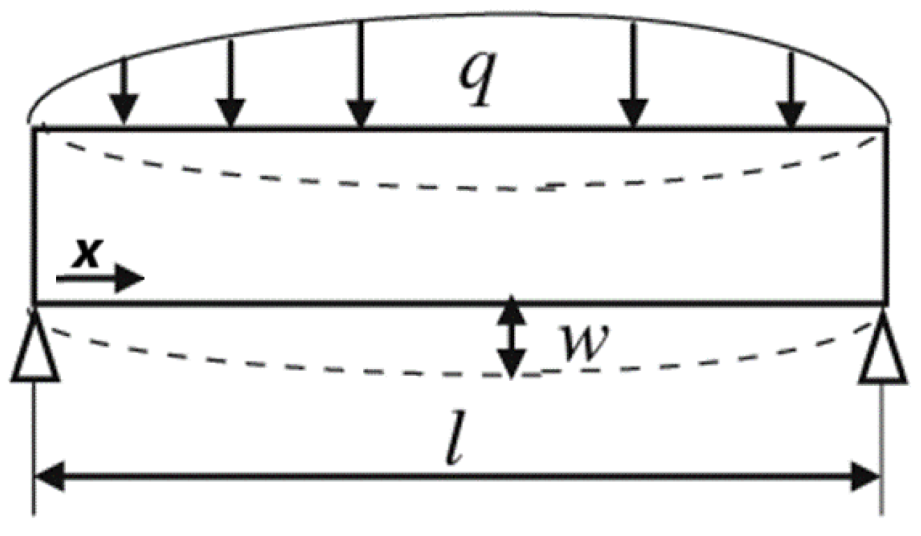
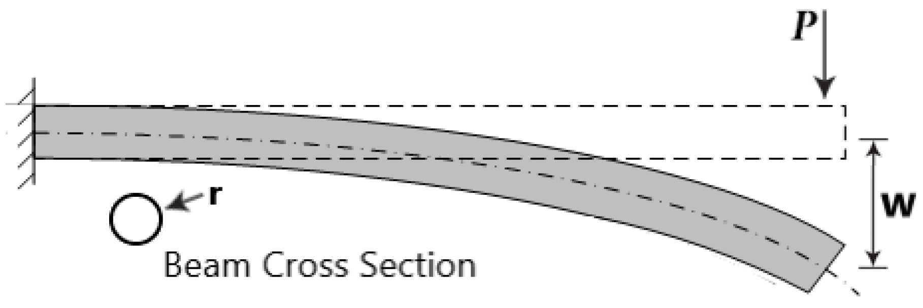
3.2. Dimensional Analysis: Deflection of Beams and Shafts
L: −2a1 + b1 = 0 → b1 = −2.
4. Method Assessment with Numerical Simulations
4.1. Advanced Dimensional Analysis for a Scaled Shafting System Model
- Geometric Parameters: Shaft length and Shaft diameter.
- Load-Related Parameters: Shaft weight, External loads, and Shaft speed.
- Material Properties Parameters: Modulus of elasticity and Shaft inertia.
- Support Configuration Parameters: Bearing locations and Vertical offset.
4.2. Dimensional Analysis for Journal Bearing Model
- Ease of Use: The Sommerfeld number is a straightforward, simple to use non-dimensional parameter applicable to any conventional journal bearing.
- Comprehensive Assessment: It encompasses both design and operational aspects.
- Performance Characterization: It effectively characterizes the bearing’s performance.
- Comparative Analysis: It facilitates comparisons between bearings under different operational conditions or with different designs.
- 1.
- Simplified Bearing Geometries: The Sommerfeld number approach relies on simplified bearing geometries, which may not accurately represent the complexities of real-world bearings.
- 2.
- Misalignment Influence: Investigations into journal bearings have revealed that misalignment, especially under heavy loads and significant misalignment angles, substantially affects both the static and dynamic characteristics of the bearings. Existing methods often fall short in assessing such scenarios.
- 3.
- Elastic Deformation Influence: It does not account for any elastic deformation effects.
- 4.
- Surface Detail Omission: Surface roughness or texturing data is not included.
- 5.
- Uniform Load Assumption: It assumes a uniform distribution of radial load W.
- 6.
- Static Operating Condition: It is applicable mainly for “static” operating conditions.
- 7.
- Inadequate Consideration of Operating Conditions: Traditional approaches struggle to account for various operating conditions and environmental factors that significantly impact bearing performance.
- 8.
- Lubricant Assumption: It assumes that the clearance is always filled with lubricant, without considering oil starvation scenarios.
4.3. Coupled Dimensional Analysis towards a Similar Small-Scale Model
- 1.
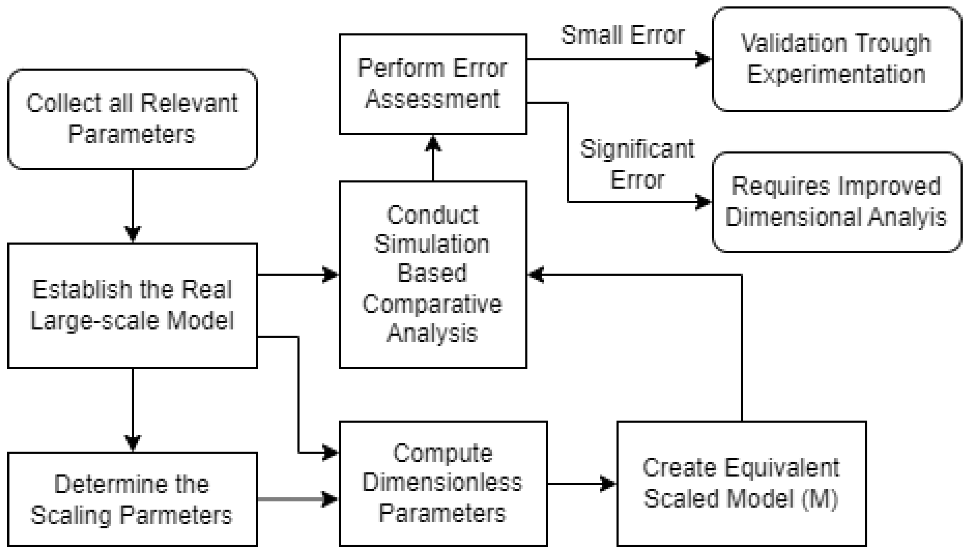
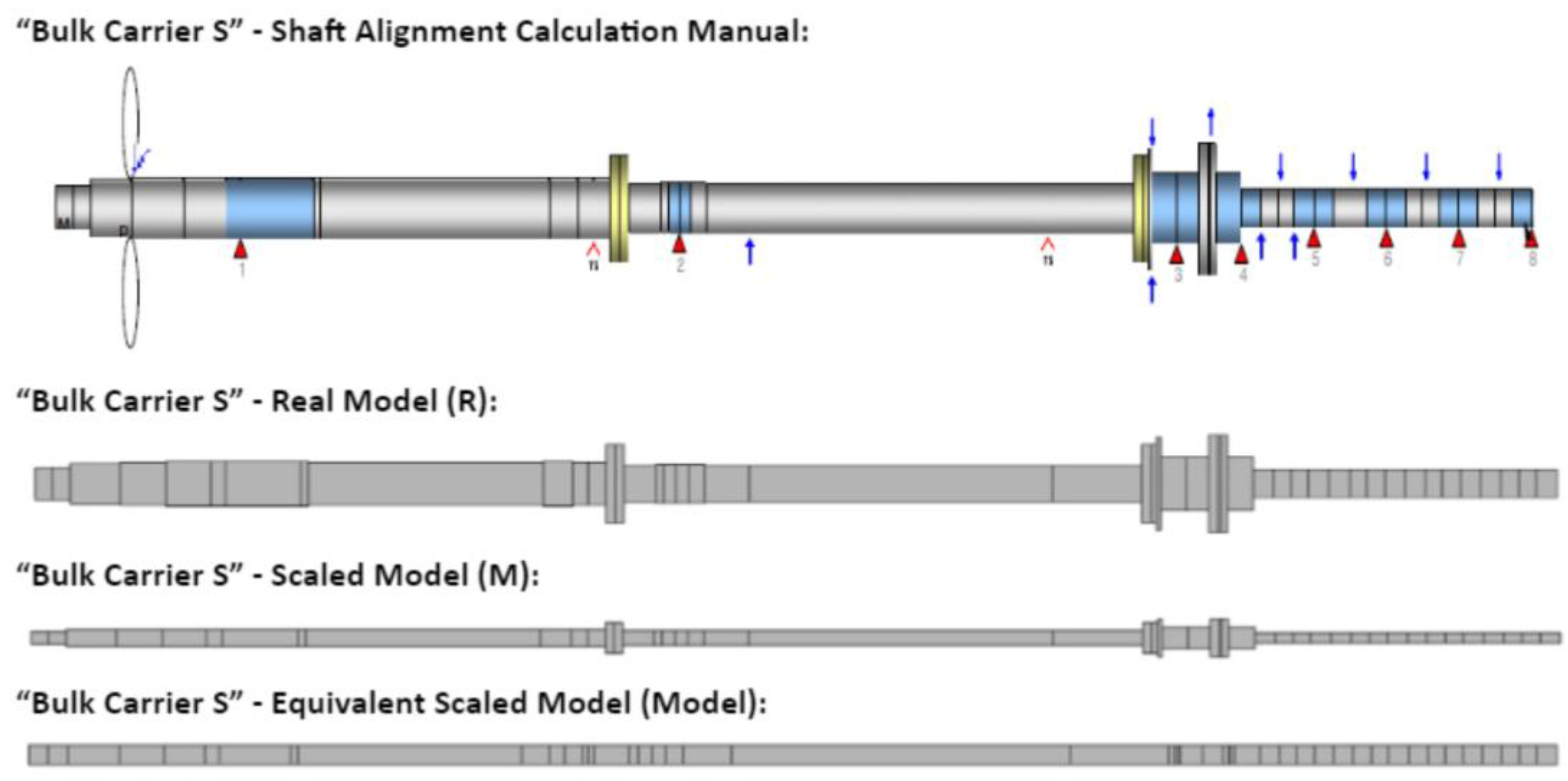
- Establish Real Model (R): Begin by developing a full-scale real model of the marine shafting system, following the Scaling Methodology. This real model serves as the reference for the scaled-down model.
- 2.
- Determine Scaling Parameters: Apply the Scaling Methodology to determine the appropriate scaling parameters and ratios.
- 3.
- Dimensional Analysis: Apply Advanced Dimensional Analysis Methodology to compute the dimensionless parameters that capture the system’s behavior under various operating conditions. These include geometric dimensions, material properties, loadings, and rotational speeds. This step allows for a deeper understanding of how different factors affect performance. Ensure that Equations (7)–(9) and (12)–(14) are satisfied to achieve similarity between the real and scaled models.
- 4.
- Create Equivalent Scaled Model (M): Using the scaling parameters obtained in the previous step, construct a scaled-down model that closely mimics the real model. This model is designed to adhere to the geometric and mechanical constraints dictated by the Scaling Methodology.
- 5.
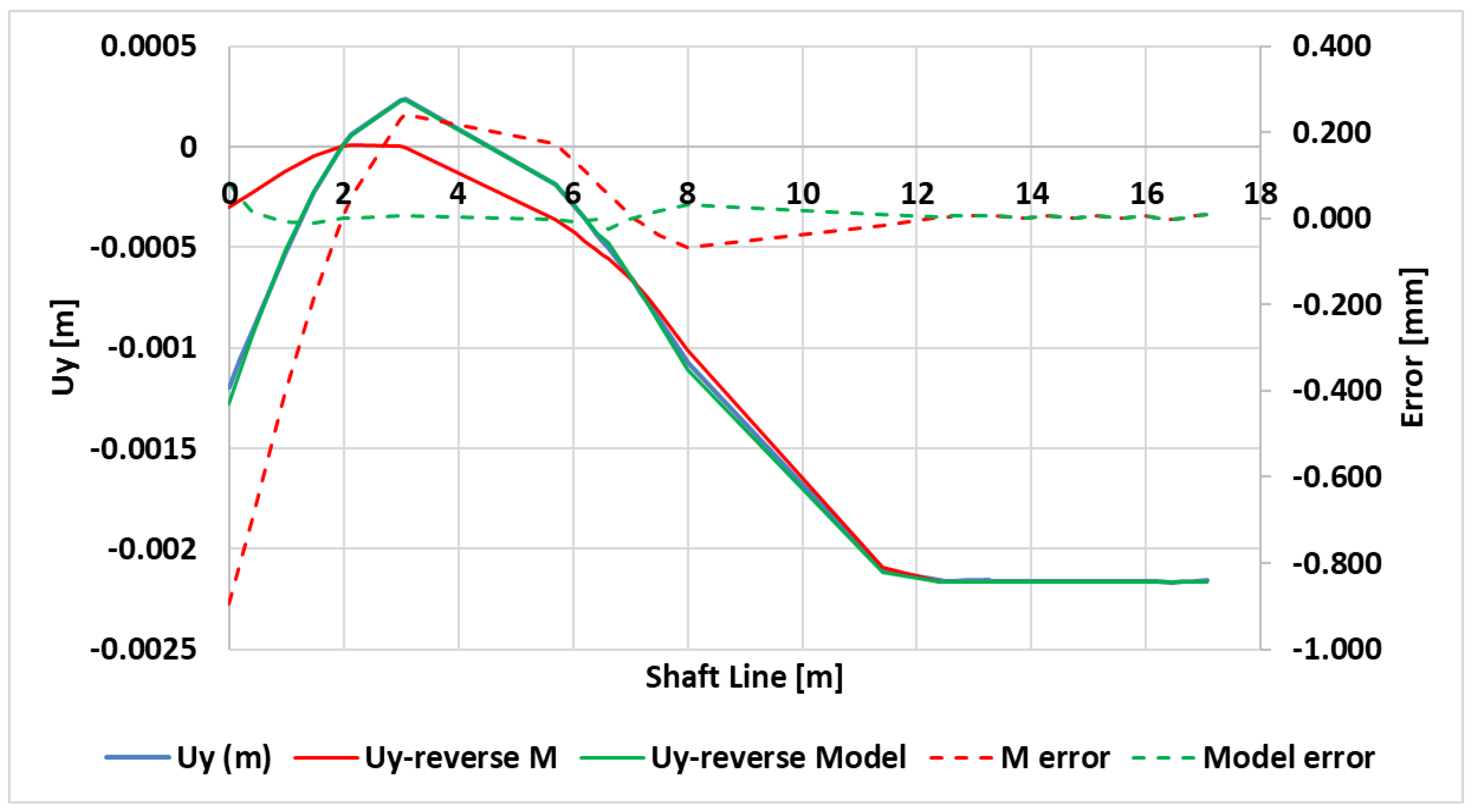
- Comparative Analysis: Conduct a comparative analysis (Shaft Alignment simulations) between the real and scaled models. Examine the performance of the scaled model under various conditions and compare it to the real system. This step ensures that the scaled model accurately represents the behavior of the full-scale system.
- 6.
- Error Assessment: Evaluate any discrepancies between the real and scaled models and assess the accuracy of the Equivalent Scaled Model.
- 7.
- Validation and Experimentation: Utilize the integrated framework for experimentation and validation. Perform laboratory tests and data collection using the scaled model to gain insights into the behavior of the full-scale shafting system.
5. Application Case Study—“Bulk Carrier S”
5.1. Model Development for Small-Scale Experimental Test-Rig
5.2. Preliminary Numerical Investigation—Available Bulk Carriers
5.3. Dimensional Analysis—“Bulk Carrier S”
- →
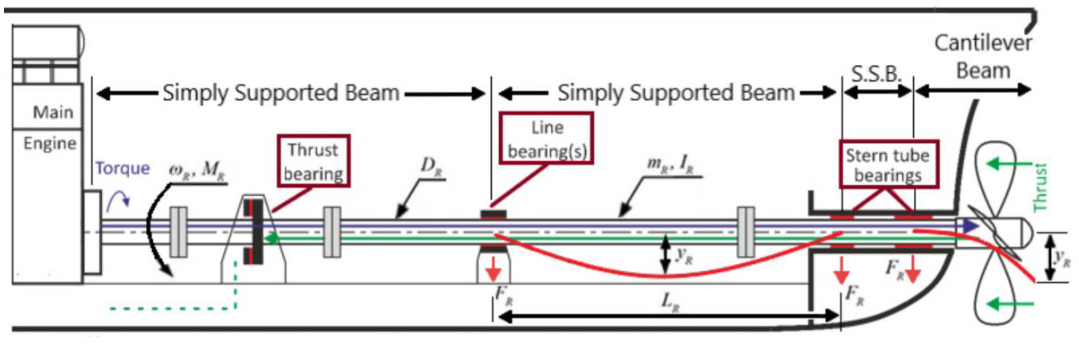
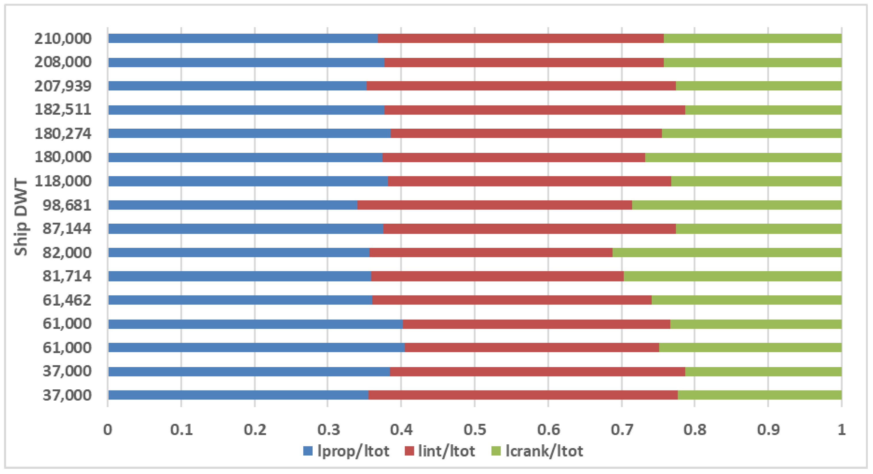
- Shaft length: The total length of the indivitual shafts, including the propeller shaft, intermediate shaft, and crankshaft.
- →
- Shaft diameters: The varying diameters of the individual shaft sections, namely the propeller shaft, intermediate shaft, and crankshaft.
- →
- Bearing types and position: The types and position of the bearings used along the shafline define the support type and location, respectively.
- →
- Bearing dimensions: Including all relevant sizes and aspect ratios.
- →
- Shaft material properties: The material composition of the shaft, including its modulus of elasticity.
- →
- Shaft weights: The weights of the different shaft sections are accounted for.
- →
- Shaft rotational speed: Shaft RPM is important for journal bearing performance.
- →
- Vertical offsets: The vertical offsets of each bearing define the shaft alignment.
- →
- Propeller loads: These details, include the propeller’s diameter, load, bending moment and eccentric trust, and determine a key external load on the system.
- →
- Main engine loads: The magnitudes and positions of these loads define most of the external loads applied on the propulsion system.
5.4. Scaled Journal Bearing Modeling and Manufacturing
- →
- Bearing Types: Different types of bearings can be identified in the ship’s “Shaft Arrangement” drawing, such as journal bearings, thrust bearings, or roller bearings.
- →
- Bearing Dimensions: Information about the dimensions of each bearing, including inner and outer diameters, width, and any specific design features can be extracted from relevant drawings.
- →
- Bearing Locations: The position of each bearing along the shaft can be determined from the “Shaft Arrangement” drawing, which helps to establish the correct support configuration and alignment in the scaled model.
- →
- Bearing Materials: The material properties influence bearing performance and should be replicated in the scaled model.
- →
- Bearing Lubrication: If available, any information regarding the lubrication systems used for the journal bearings can aid in simulating bearing behavior accurately.
- →
- Bearing Loads: The allowable load limits for each bearing along with the (expected) applied radial loads, axial loads, and bending moments should be accounted for.
- →
- Bearing Clearance: Specific information about the radial bearing clearance is critical for replicating the bearing’s operational characteristics.
- →
- Bearing Friction: If available, data associated with the coefficient of friction or the surface properties of the bearings can be essential for advanced modeling purposes.
- →
- Bearing Foundation: Details regarding the bearing’s foundation are necessary to determine the local stiffness of the support structure.
- →
- Bearing Wear: Information regarding expected bearing wear, maintenance schedules, and replacement intervals can inform the modeling of bearing performance over time.
- →
- Bearing Cooling Systems: If applicable, details about the cooling system integrated into the bearing can be crucial for accurately predicting the lubricant’s heat dissipation.
6. Discussion—Applications
7. Conclusions
Supplementary Materials
Author Contributions
Funding
Institutional Review Board Statement
Informed Consent Statement
Data Availability Statement
Conflicts of Interest
Abbreviation
| Symbol | Meaning | Unit |
| C | Bearing radial clearance | m |
| D, d | Bearing or shaft diameter | m |
| E | Young’s modulus of elasticity | Pa = N/m2 |
| F | Force (Normal or Friction) | N |
| h | Lubricant film thickness | m |
| I | Shaft inertia (cross section moment) | m4 |
| L | Bearing or shaft length | m |
| Lq | Length of distributed load | m |
| M | Shaft mass | kg |
| n | Scale ratio | - |
| Ns | Rotor angular velocity | RPS |
| p | Pressure | Pa = N/m2 |
| p0 | Environmental pressure | Pa = N/m2 |
| Q | Fluid flux | m3/s |
| qm | Mean distributed load | N/m |
| q(x) | Distributed load | N/m |
| R, r | Bearing or shaft radius | m |
| Uy | Shaft vertical position | m |
| v | Relative sliding velocity | m/s |
| W | Load | N |
| w | Shaft vertical deflection | m |
| x | Longitudinal position along the shaftline | m |
| yR | Maximum shaft deflection | m |
| η | Lubricant viscosity | Pa·s or kg/(m·s) |
| μ | Friction coefficient | - |
| ρ | Density | Kg/m3 |
| ω | Angular velocity | RPS or RPM |
References
- Buckingham, E. On Physically Similar Systems: Illustrations of the use of dimensional equations. Phys. Rev. 1914, 4, 345–376. [Google Scholar] [CrossRef]
- Buckingham, E. Physically similar systems. Acad. Sci. 1914, 93, 347–353. [Google Scholar]
- Korczewski, Z.; Marszałkowski, K. Energy analysis of the propulsion shaft fatigue process in a rotating mechanical system part III dimensional analysis. Pol. Marit. Res. 2021, 28, 72–77. [Google Scholar] [CrossRef]
- Korczewski, Z.; Marszałkowski, K. Energy analysis of propulsion shaft fatigue process in rotating mechanical system. Part I. Testing significance of influence of shaft material fatigue excitation parameters. Pol. Marit. Res. 2018, 25, 211–217. [Google Scholar] [CrossRef]
- Korczewski, Z.; Marszałkowski, K. Energy analysis of propulsion shaft fatigue process in rotating mechanical system. Part II. Identification studies—Developing the fatigue durability model of a propulsion shaft. Pol. Marit. Res. 2020, 27, 120–124. [Google Scholar] [CrossRef]
- Korczewski, Z. The conception of energetic investigations of the multisymptom fatigue of the simple mechanical systems constructional materials. J. Pol. CIMAC 2012, 7, 99–108. [Google Scholar]
- Zohuri, B. Dimensional Analysis beyond the Pi Theorem; Springer International Publishing: Cham, Switzerland, 2017; Volume 1. [Google Scholar]
- Tan, Q.M. Dimensional Analysis: With Case Studies in Mechanics; Springer Science & Business Media: Berlin/Heidelberg, Germany, 2011. [Google Scholar]
- Taylor, E.S. Dimensional Analysis for Engineers; Oxford University Press: Oxford, UK, 1974. [Google Scholar]
- Rossopoulos, G.N.; Papadopoulos, C.I.; Leontopoulos, C. Tribological comparison of an optimum single and double slope design of the stern tube bearing, case study for a marine vessel. Tribol. Int. 2020, 150, 106343. [Google Scholar] [CrossRef]
- Theofilis, P.; Rossopoulos, G.N.; Papadopoulos, C.I. Solution Space and Optimality Concerns for the Shafting System Alignment of a Typical Bulk Carrier. In Proceedings of the SNAME International Symposium on Ship Operations, Management and Economics, Athens, Greece, 7 March 2023; p. D021S006R002. [Google Scholar]
- Zhou, W.; Zhao, Y.; Yuan, H.; Ren, Z. Experimental Study on the Effect of Hull Deformation on the Relative Attitude between Shaft and Bearing. J. Mar. Sci. Eng. 2023, 11, 1992. [Google Scholar] [CrossRef]
- Zhou, W.; Zhao, Y.; Yuan, H.; Wang, X. Study of the Hull Structural Deformation Calculation Using the Matrix Displacement Method and Its Influence on the Shaft Alignment. J. Mar. Sci. Eng. 2023, 11, 1495. [Google Scholar] [CrossRef]
- Choi, S.P.; Lee, J.U.; Park, J.B. Application of deep reinforcement learning to predict shaft deformation considering hull deformation of medium-sized oil/chemical tanker. J. Mar. Sci. Eng. 2021, 9, 767. [Google Scholar] [CrossRef]
- Vignaux, G.A. Dimensional Analysis in Data Modelling. In Maximum Entropy and Bayesian Methods; Fundamental Theories of Physics (An International Book Series on The Fundamental Theories of Physics: Their Clarification, Development and Application); Smith, C.R., Erickson, G.J., Neudorfer, P.O., Eds.; Springer: Dordrecht, The Netherlands, 1992; Volume 50. [Google Scholar]
- Wen, X.; Zhou, R.; Yuan, Q.; Lei, J. Coupling Mathematical Model of Marine Propulsion Shafting in Steady Operating State. J. Shanghai Jiaotong Univ. Sci. 2020, 25, 463–469. [Google Scholar] [CrossRef]
- Jadhav, P.M.; Kumbhar, S.G.; Desavale, R.G.; Patil, S.B. Distributed fault diagnosis of rotor-bearing system using dimensional analysis and experimental methods. Measurement 2020, 166, 108239. [Google Scholar] [CrossRef]
- Vizentin, G.; Vukelic, G.; Murawski, L.; Recho, N.; Orovic, J. Marine propulsion system failures—A review. J. Mar. Sci. Eng. 2020, 8, 662. [Google Scholar] [CrossRef]
- Vizentin, G.; Vukelić, G.; Srok, M. Common failures of ship propulsion shafts. Pomorstvo 2017, 31, 85–90. [Google Scholar] [CrossRef]
- Rossopoulos, G.N.; Papadopoulos, C.I. AI techniques for evaluating misaligned journal bearing performance: An approach beyond the Sommerfeld number. Proc. Inst. Mech. Eng. Part J J. Eng. Tribol. 2024, 238, 733–743. [Google Scholar] [CrossRef]


| Quantity | Common Symbol (s) | Dimensions | |
|---|---|---|---|
| Geometry | Area | A | L2 |
| Second moment of area | I | L4 | |
| Volume | V | L3 | |
| Kinematics | Acceleration | α | LT−2 |
| Angle | θ | 1 (i.e., dimensionless) | |
| Angular velocity | ω | T−1 | |
| Mass flow rate | ṁ | MT−1 | |
| Quantity of flow | Q | L3T−1 | |
| Velocity | U | LT−1 | |
| Dynamics | Energy, work, heat | E, W | ML2T−2 |
| Force | F | MLT−2 | |
| Power | P | ML2T−3 | |
| Pressure, stress | p, τ | ML−1T−2 | |
| Torque, Moment | T | ML2T−2 | |
| Fluid properties | Bulk modulus | K | ML−1T−2 |
| Density | ρ | ML−3 | |
| Kinematic viscosity | ν | L2T−1 | |
| Specific heat | cp, cv | L2T−2Θ−1 | |
| Surface tension | σ | MT−2 | |
| Thermal conductivity | k | MLT−3Θ−1 | |
| Viscosity | η | ML−1T−1 |
| Prototype | R | h | W | p0 |
| Model | R/n | h/n | W/n | n × p0 |
| Quantity | Symbol | MLT |
|---|---|---|
| Applied Force | F | F |
| Deflection | w | L |
| Modulus of Elasticity | E | FL−2 |
| Beam Radius | R | L |
| Beam Length | L | L |
| Parameter Calculation | |
|---|---|
| Reality | Model |
| Dr | Dm = Dr/n |
| LR | Lm = Lr/n2/3 |
| ER | EM |
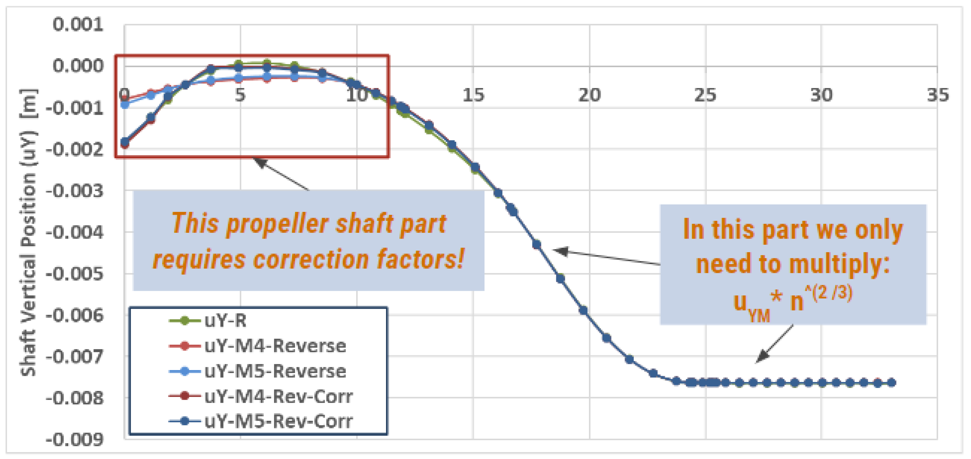
| Vertical_DisplacementR | Vertical_DisplacementM = Vertical_DisplacementR/n2/3 |
| ForceR | ForceM = ForceR/n3 |
| Model 4 Reverse | Model 5 Reverse | |
|---|---|---|
| n (shaft diameter ratio) | 69 | 27.6 |
| Dpropeller (at ASTB) | 10 mm | 25 mm |
| Average Relative Error % | 0.009 | 0.010 |
| Standard Deviation of Error | 0.0496 | 0.0560 |
| L/D | D [m] | L [m] | R [m] | c [m] | η [Pa s] | N [RPM] | W [N] | S | |
|---|---|---|---|---|---|---|---|---|---|
| R1 | 1 | 0.45 | 0.45 | 0.225 | 0.00045 | 0.05 | 90 | 100,000 | 0.03797 |
| R2 | 2 | 0.45 | 0.9 | 0.225 | 0.00045 | 0.05 | 90 | 500,000 | 0.01519 |
| M1 1:18 | 1 | 0.025 | 0.025 | 0.0125 | 0.00026 | 0.07 | 1440 | 63.9 | 0.03797 |
| M2 1:18 | 2 | 0.025 | 0.05 | 0.0125 | 0.00026 | 0.07 | 1440 | 319.6 | 0.01519 |
| Average | St.Dev. | |
|---|---|---|
| Lprop/Ltot | 0.368 | 0.023 |
| Lint/Ltot | 0.377 | 0.028 |
| Lcr/Ltot | 0.255 | 0.040 |
| Dprop/Dfl_prop | 0.617 | 0.066 |
| Dint/Dfl_int_aft | 0.506 | 0.057 |
| Dint/Dfl_int_fore | 0.431 | 0.055 |
| Dcr/Dfl_cr | 0.355 | 0.044 |
| Lfl_prop/Lprop | 0.015 | 0.003 |
| Lfl_int/Lint | 0.014 | 0.002 |
| Lfl_cr/Lcr | 0.015 | 0.008 |
| qmL3/EI | Average | St.Dev. |
|---|---|---|
| Prop | 0.705 | 0.167 |
| Int | 1.122 | 0.296 |
| Crank | 0.461 | 0.154 |
| Model | M | |
|---|---|---|
| n (ratio) | 20.4 | 20.4 |
| Dpropeller (ASTB) | 25 mm | 25 mm |
| Average Error % | 0.005 | −0.039 |
| St.Dev. of Error | 0.015 | 0.216 |
Disclaimer/Publisher’s Note: The statements, opinions and data contained in all publications are solely those of the individual author(s) and contributor(s) and not of MDPI and/or the editor(s). MDPI and/or the editor(s) disclaim responsibility for any injury to people or property resulting from any ideas, methods, instructions or products referred to in the content. |
© 2024 by the authors. Licensee MDPI, Basel, Switzerland. This article is an open access article distributed under the terms and conditions of the Creative Commons Attribution (CC BY) license (https://creativecommons.org/licenses/by/4.0/).
Share and Cite
Rossopoulos, G.N.; Papadopoulos, C.I. A π-Theorem-Based Advanced Scaling Methodology for Similarity Assessment of Marine Shafting Systems. J. Mar. Sci. Eng. 2024, 12, 894. https://doi.org/10.3390/jmse12060894
Rossopoulos GN, Papadopoulos CI. A π-Theorem-Based Advanced Scaling Methodology for Similarity Assessment of Marine Shafting Systems. Journal of Marine Science and Engineering. 2024; 12(6):894. https://doi.org/10.3390/jmse12060894
Chicago/Turabian StyleRossopoulos, Georgios N., and Christos I. Papadopoulos. 2024. "A π-Theorem-Based Advanced Scaling Methodology for Similarity Assessment of Marine Shafting Systems" Journal of Marine Science and Engineering 12, no. 6: 894. https://doi.org/10.3390/jmse12060894
APA StyleRossopoulos, G. N., & Papadopoulos, C. I. (2024). A π-Theorem-Based Advanced Scaling Methodology for Similarity Assessment of Marine Shafting Systems. Journal of Marine Science and Engineering, 12(6), 894. https://doi.org/10.3390/jmse12060894