Article

Combining Lightness and Stiffness through Composite-Reinforced Additive Manufacturing in the Yacht Industry: Case Study Analysis and Application on Large Functional Components

1
Nugae, 22074 Lomazzo, Italy
2
Dipartimento di Design, Politecnico di Milano, 20158 Milan, Italy
*
Author to whom correspondence should be addressed.
J. Mar. Sci. Eng. 2024, 12(6), 918; https://doi.org/10.3390/jmse12060918
Submission received: 11 April 2024 / Revised: 24 May 2024 / Accepted: 27 May 2024 / Published: 30 May 2024

Abstract

:
This paper explores applications of additive manufacturing (AM) for producing structural components in the yacht industry. Several case studies illustrate how AM is applied to create lightweight composite panels and complex geometries that are challenging to produce with traditional methods. Experimental and simulation studies demonstrate the mechanical performance of AM-produced parts. The key benefits demonstrated include design flexibility and zero-tool manufacturing. The potential roles of AM in addressing industry challenges, such as customisation possibilities and more sustainable production methods, are discussed. The case studies indicate the technical feasibility of 3D printing for functional yacht applications across various scales. Overall, AM shows promise in revolutionising design and manufacturing approaches by enabling optimised structures and on-demand production without traditional manufacturing constraints. This research study highlights the technology’s role in evolving yacht design and production practices.

1. Introduction

The main composite manufacturing techniques employed in the maritime industry are based on the use of moulds and dies not only to produce hulls and appendages but also to fabricate most of the components for interiors and decks. These processes present several limitations that slow down the evolution of the nautical industry because of their lack of flexibility, environmental impact [1], and high cost [2].
The tools employed represent a significant environmental challenge, especially when they cannot be reused on a sufficient number of products to balance their impact. Furthermore, the use of moulds limits the possibility of customising the product shape and requires new moulds even when minimal design changes are needed.
To address these challenges more effectively, the industry is actively embracing Industry 4.0 advancements via the gradual and increasing implementation of additive manufacturing (AM) [3].
The term AM, commonly known as 3D printing, refers to a wide range of technologies enabling the creation of objects layer by layer, starting from a digital model [4,5]. According to Attaran [6], the two most common AM technologies are fused deposition modelling (FDM) and selective laser sintering (SLS). FDM involves melting a thermoplastic filament through a heated extruder and depositing it layer by layer on a building platform. Known for its simplicity and cost-effectiveness, FDM is widely used for rapid prototyping and custom component manufacturing. SLS uses a laser to sinter powdered material, such as nylon or polyamide, into a solid structure. A laser scans the cross-sections generated from a 3D digital model, sintering only the powder needed to create each layer. Unused powder supports overhangs and thermally shields the material from the laser, allowing the production of complex geometric parts in a single operation. Weller et al. [7] observed that AM is particularly beneficial in settings with a high demand for tailored or personalised products, complex designs, and flexible production processes.
These findings underscore the suitability of 3D printing for the maritime industry, and a literature review regarding their implementation in this field shows that these technologies are mainly used in four areas of application: boat prototypes, moulds, spare parts, and custom components. Although the maritime industry lags behind the aerospace and automotive industries in adopting AM [8], this approach can potentially revolutionise production systems, paving the way for significant advantages.
Design freedom represents one of the most relevant aspects offered by these technologies. This unparalleled capability to craft complex shapes enables the optimisation of structures, resulting in reduced weight and enhanced performance [9,10]. This ability, therefore, facilitates innovative and cutting-edge solutions, allowing the exploration of pioneering scenarios in manufacturing advanced and highly efficient components. The Smart Wheel, printed by Superfici, exemplifies this potential [11]. This steering wheel prototype features intricately optimised shapes achieved through generative design tools. AM also has shown its effectiveness in the production of entire boats.
Another visionary approach is presented in the megayacht concept Pegasus 88m [12]. Designed by Jozeph Forakis, this visionary project features a 3D-printed framework for both the hull and superstructure.
The first 3D-printed motorboat is the MAMBO (Motor Additive Manufacturing BOat) [1,12,13]. At 800 kg, the prototype showcased a 30% reduction in weight compared to vessels of comparable sizes; in addition, it demonstrated the potential of the technology used, for example, in conceiving surface morphologies characterised by undercuts for which would be impossible or, in any case, complex to use laminating composites in moulds. The 3Dirigo patrol boat, fabricated by the University of Maine’s Advanced Composites Center through a bespoke 3D-printing system, initially held the distinction of being the largest single-operation 3D-printed object, at 7.62 m in length [14]. However, this record has since been surpassed by a water taxi collaboratively manufactured by Al Seer Marine and Abu Dhabi Maritime, with a length of 11.38 m [15].
As highlighted by Brun and Karaosman [16], the trend towards customisation is constantly increasing in the yacht market. AM could be a fundamental catalyst for this growing trend thanks to its flexible production processes that do not require traditional tools [17,18]. Therefore, each product can be unique and tailored to fit the specific needs of each end user or application [19]. The Sacs Marine 700 console [14] and the speaker housings for Tankoa Yachts [1], produced by Superfici, clearly demonstrate the extensive possibilities of AM in enabling customised solutions. Tanaruz, a Dutch company, specialises in the manufacture of customisable runabouts using additive techniques [12]. These boats vary in length from 4.5 to 7.5 m. Similarly, IMPACD Boats, another Dutch manufacturer, partners with firms like Royal 3D and 10XL to create small vessels utilising recycled materials, with a focus on sustainability [20].
Experimentations with AM have also been carried out for both positive and negative moulds. In 2017, Thermwood 3D printed a positive mould for a production-series skiff using its proprietary technology, Large Scale Additive Manufacturing (LSAM) [1]. Crafted in 12 sections, the negative catamaran hull mould created by Oak Ridge National Laboratory was produced through its developed technology, called Big Area Additive Manufacturing (BAAM). [14,21].
These changes in the production process allow the maritime industry to offer different configurations of its product ranges in the catalogue without incurring extra costs while maintaining time-to-market standards.
AM allows for precise material control, minimising waste by using only the amount required to create desired objects. This technique enhances sustainability by reducing production waste [6] and contributes to cost efficiencies across the production process.
This paper presents the benefits of this technology for creating boats and components with an optimised design and performance, examining its applications and related case studies in the maritime industry. In Section 2, the technology and main applications are introduced and thoroughly described. Selected case studies are presented in Section 3, while Section 4 discusses the strengths and limitations of the presented methodology, as well as future research scenarios. Finally, conclusions are drawn in Section 5.

2. Materials and Methods: Description of the Technology Used
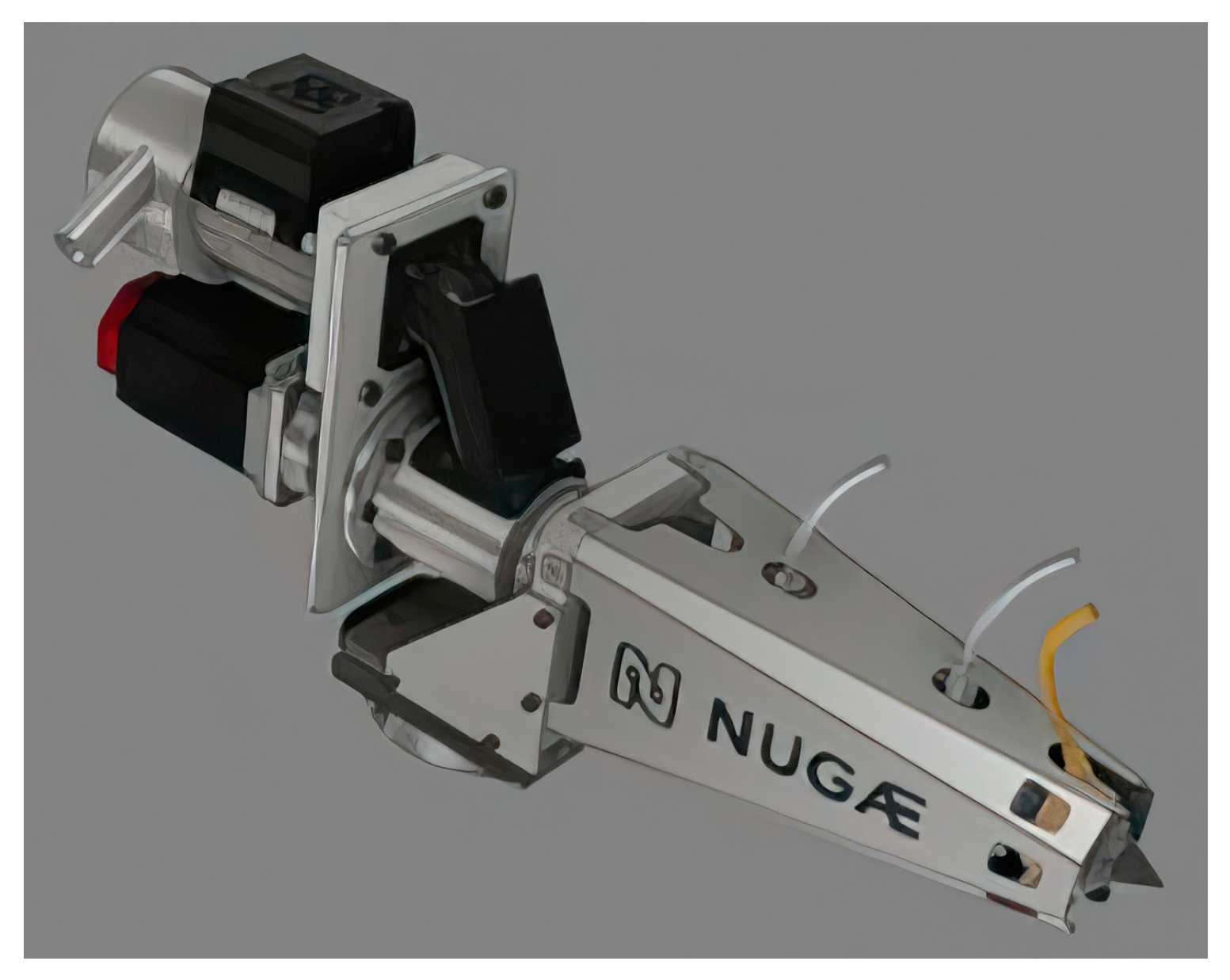
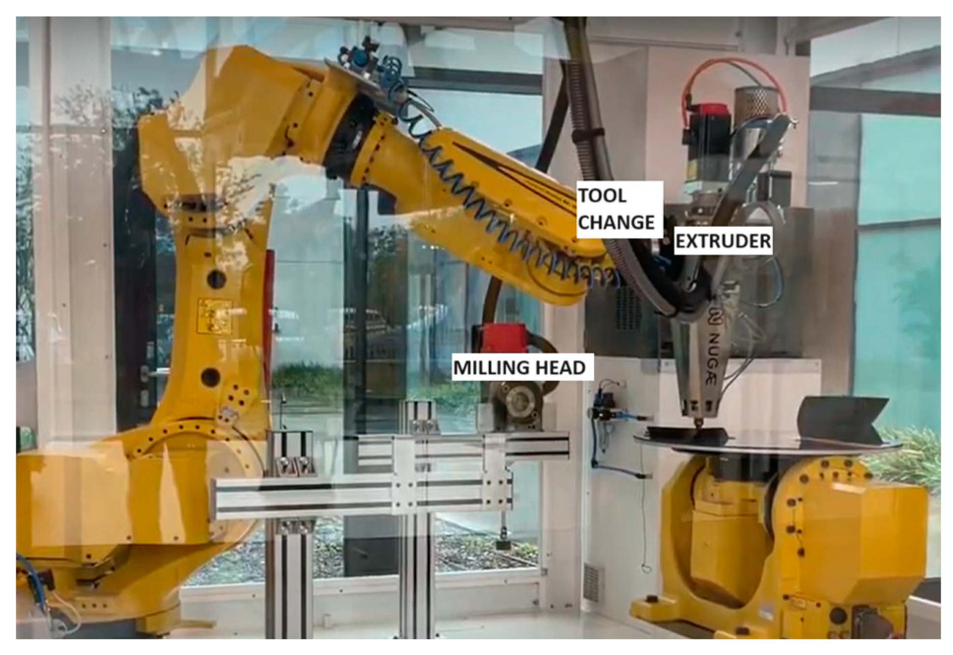
2.1. The Robot

The technology employed in our AM system involves the integration of an anthropomorphic robot, specifically the Fanuc M8001a model (Fanuc corporation, Shibokusa, Japan), with an innovative micro-extruder crafted by Nugae (Figure 1 and Figure 2). This micro-extruder utilises a 15 mm screw design with coaxial feeding; the extrusion nozzles range from 0.9 to 1.2 mm in diameter, with a 1 mm nozzle used for the applications detailed in the subsequent sections.
The Nugae extrusion head incorporates a liquid cooling system to regulate temperature throughout the extrusion process. A feed duct, incorporating a vibrator, serves the crucial function of preventing granule blockage, ensuring continuous and uninterrupted material flow during extrusion. Additionally, a Venturi suction system directs materials to a hopper positioned at the apex of the robotic system. The materials are then pushed into the barrel by the screw and melted through the heating band.
Downstream of the extrusion system, a suite of units contributes to the overall efficiency and precision of the manufacturing process. These units encompass facilities for granule drying, extruder cooling, and meticulous temperature control over the heating bands. The cohesive functioning of these components is paramount to achieving a controlled and optimised extrusion process, yielding high-quality printed components.
The arm has a maximum circular extension of a radius of 2040 mm and can print parts up to 1400 mm in height. Larger configurations include robotic arm extensions of up to 3100 mm.
Our system embodies a transformative tool change feature. This functionality facilitates the shift of the 3D-printing unit, allowing for the integration of a milling unit, which enables post-processing capabilities geared explicitly towards refining and smoothing the printed components. This strategic adaptability further underscores the system’s versatility and ability to cater to diverse post-processing requirements.
The nuanced features, such as liquid cooling, granule blockage prevention, and tool change capability, exemplify the commitment to achieving excellence in 3D-printing technology while anticipating and accommodating evolving demands in multifunctional AM processes.

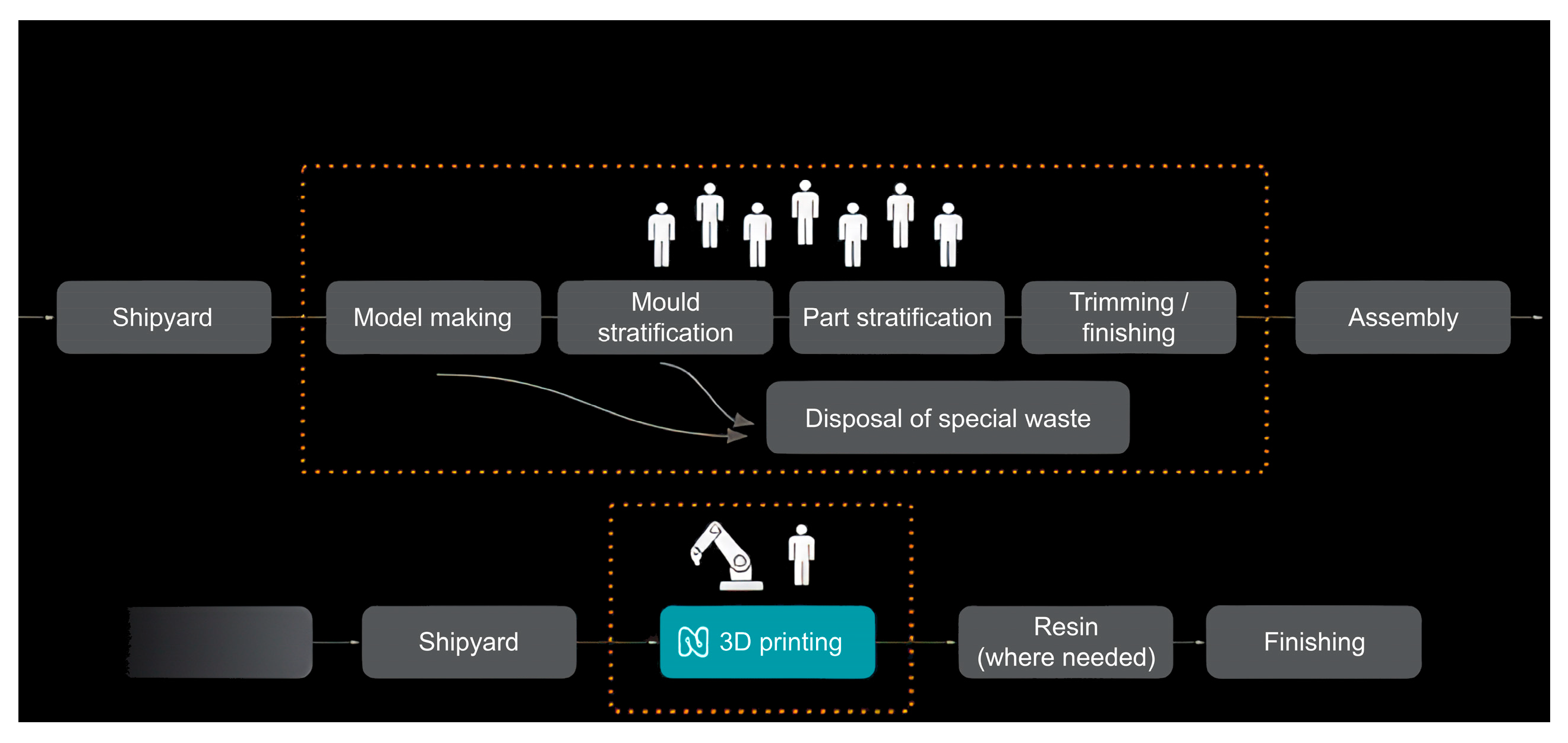
2.2. The Strategic Approach

The strategic approach for printing components involved maintaining a constant speed of 250–300 mm/s, with control points along the path (except at corners) at 3 mm intervals and a layer thickness of 0.4 mm. The width of the 3D-printed walls ranged between 1.5 and 2 mm.
The slicing approach was driven from a single continuous line without infills, using a constant extruder screw speed of 25 rpm. To reach adequate stiffness on planar surfaces, we used self-intersecting surfaces with hollow ribs, as illustrated in Figure 3. Curved surfaces were designed to have enough shape stiffness to counteract deformations due to thermal retraction.
The 3D-printing robot system underwent calibration for precision in producing large-sized components featuring thin walls and mechanical characteristics that are optimised for applications in the maritime industry.
The scope of the evaluated components encompasses critical elements such as hull and deck panels and boxed structures for superstructures. These components seamlessly integrate with external glass/carbon composite materials, providing strength and durability. Additionally, a novel technique allows for the internal integration of these composite materials, expanding design possibilities and structural capabilities.
Noteworthy is the capability of the system to manufacture components with secondary structural functions, particularly for interiors, without any additional composite reinforcement. This breakthrough streamlines the manufacturing process and underscores the technology’s versatility in producing lightweight yet robust interior components.
The customisation potential of this technology is exemplified by its ability to create bespoke components with dimensions reaching several metres and extremely thin thicknesses of 1–2 mm. As exemplified in Figure 4, this direct manufacturing approach significantly alleviates the burden on shipyards by obviating the necessity for traditional mould and model creation. Consequently, this substantially reduces both the labour hours required for models and mould realisation and the overall volume of generated waste.

2.3. The Software

The software used for model generation utilises Python Version Nugae.002 scripts within the Rhinoceros/Grasshopper platform. This software enables the creation of paths with geometric scaling and exports them with a discretisation of approximately 3 mm between successive points. The resulting files are then exported as ready-to-print scripts in the Fanuc language using Grasshopper, achieving seamless integration with the AM system.
File generation is based on two steps, the first being geometric processing that allows, starting from the selection of surfaces, for the generation of hollow ribs with a sinusoidal shape (shown in Figure 5). At this time, we can specify the amplitude and length of the curves and the section type, typically circular or rectangular, with dimensions suitable for constructing the object. These factors are not fully automated but benefit from the experience and assessment of the operator/CAD designer in achieving sufficiently rigid geometry and a frame that can support the object’s stress.
In this case, the main advantage of the software lies in its ability to automatically generate ribs on a surface, with options related to tapering the ends at the start and end points of the geometry to create self-supporting structures without the risk of structural collapse at the start and end points.
The slicing software is based on a Grasshopper diagram with 3 INPUT data sections. In the first section, called “geometries”, it is possible to select the reference geometry, the direction orthogonal to the slicing plane, and a line close to the object’s surface where the transitions between two sections occur. For this type of approach, closed geometries that generate closed sections are considered.
In the second section, called “slicing parameters”, it is possible to define the height of the layers and the width of the connection between one curve and the next.
Finally, parameters related to “point generation” are defined, allowing for a choice between a denser or less dense distribution of control points, thus balancing speed and precision.
A data file-writing section is also defined, which implements the encoding of robot commands and the file’s writing directories. After processing, the program can identify any unclosed curves; moreover, if several closed curves are present on the same plane, it is possible to join them with a path segment to generate a single and continuous path.
This approach is based on a patented technique (Patent No. 102020000023260) for creating ribbed structures. The patented technology addresses the challenge of providing shell-like or plate-like supporting structures, requiring a delicate balance between form rigidity and lightness. The software can achieve the rapid integration of boxed reinforcement structures, optimising the production process’s speed and the components’ intrinsic lightness.
In practical terms, the software controls the data export and generates self-intersecting tubular cavities along the object’s surface to be printed. In some applications, these cavities are reinforced internally with pre-impregnated composite sleeves compacted with inflated tubular bags within the structures. This method allows for significant composite stiffening in the transverse direction relative to that of the deposition without compromising the final finish. In other applications, as described later, 3D-printed parts are exclusively reinforced on the outer surface, highlighting the adaptability and versatility of the software in accommodating various structural requirements.

2.4. Materials

Comprehensive production tests and comparisons have been executed to identify the most suitable materials for maritime applications through extensive cooperation with specialised suppliers in plastic production. This evaluation phase spanned diverse critical parameters, carefully addressing the requirements and challenges inherent in the marine environment. These considerations included the adhesion of composite skins, resilience against atmospheric agents, dimensional stability, mechanical strength, and an unwavering resistance to salt spray. We aimed to select materials that meet and exceed the stringent standards demanded by the complex conditions of maritime applications.
The examination and testing of various materials commonly used in 3D printing, including PLA (polylactic acid), ASA-PC (acrylic–styrene–acrylate terpolymer plus polycarbonate), ABS CF (acrylonitrile butadiene styrene plus carbon fibre), PA 66, and PA 12 (also known as Nylon 12), were carried out. Each material was carefully evaluated based on the application’s requirements and critical factors, such as resistance to atmospheric agents and durability in marine conditions.
Following an analysis of the test results, we chose a polycarbonate reinforced with 20% carbon fibre as the material for the illustrated application: LNP THERMOCOMP DC004xxar. This selection was based on the materials’ good adhesion with composite materials and stability in humid conditions, which are crucial factors in maritime applications. However, it is essential to highlight that this material requires protection from ultraviolet (UV) rays since maritime applications are exposed to intense sunlight.
While an exhaustive examination was conducted on various materials, as shown in Table 1, PA 12 and ABS CF were not selected for the primary application; their properties and characteristics suggest potential suitability for specific requirements in forthcoming advancements or specialised applications within the maritime sector.

3. Results of Case Studies

3.1. Case Study 1: 3D-Printed Fibreglass Structural Panels

3.1.1. Objective

This case study aimed to demonstrate that 3D-printed and vacuum-laminated composite panels can match the mechanical performance of conventional sandwich balsa core panels that are widely used in the maritime industry, particularly regarding stiffness and weight. These panels have various applications in the maritime field, such as compartmentalisations, hull and deck panels, tanks, and superstructures.
It is also possible to rapidly fabricate components characterised by integrating shell structures reinforced with a network of stiffening hollow ribs. This method, encapsulated under the patent titled “Procedure for creating a load-bearing structure in the form of a shell or plate,” enables the customisation of the thermoplastic core’s geometry (in terms of the shape, density, and rib height) along with the strategic selection of materials for both the core and the laminates. Consequently, it is possible to adapt and engineer panels with tailored mechanical properties, adjusting stiffness and weight to meet specific requirements. Each component produced through this method is thus designed for its intended structural role. An illustrative example of this capability is demonstrated with a square panel (Figure 6) that is engineered to withstand hydrostatic pressures of up to 250 kPa, conforming to the standards outlined in ISO 12215.

3.1.2. Methodology

The panels were designed to have a global stiffness comparable to that of a conventional balsa sandwich panel (Type B panel) with a thickness of 42 mm and a 2 mm balanced vacuum-bagged vinyl ester composite skin when subjected to a three-point bending test. In pursuit of the case study objectives, the following procedure was executed:
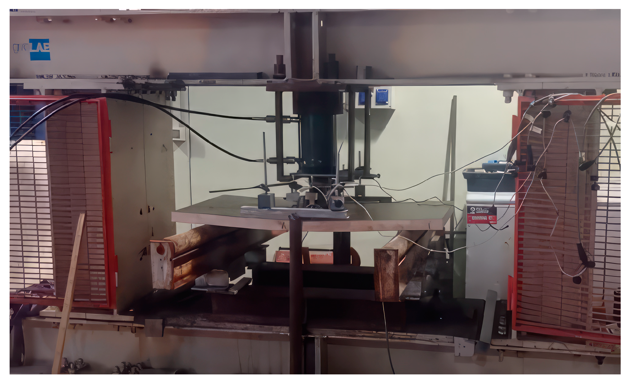
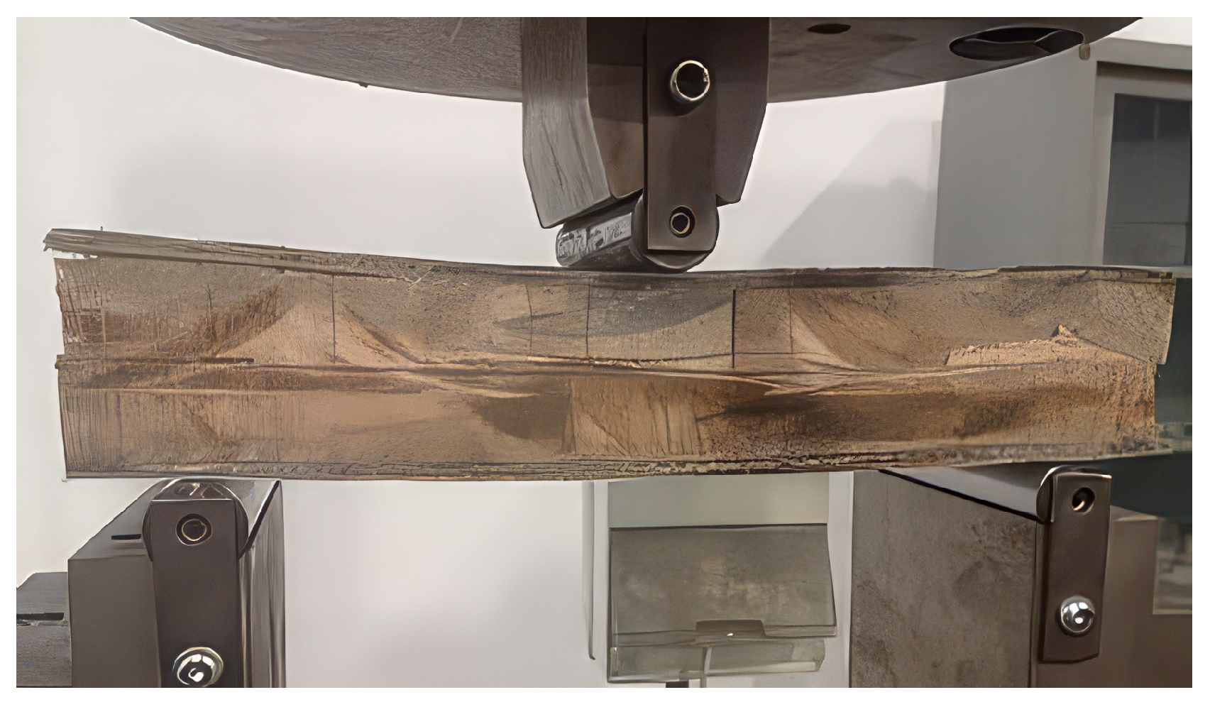
  • Three-point bending tests were performed following ASTM C393 standards on scaled-down test specimens (250 × 100 mm), involving three sets of specimens: (a) two samples derived from the Type B balsa sandwich panel, (b) two 3D-printed ribs vacuum-bag-laminated with polyester resin and glass fibre, and (c) two 3D-printed ribs vacuum-bag-laminated with epoxy resin and glass fibre;
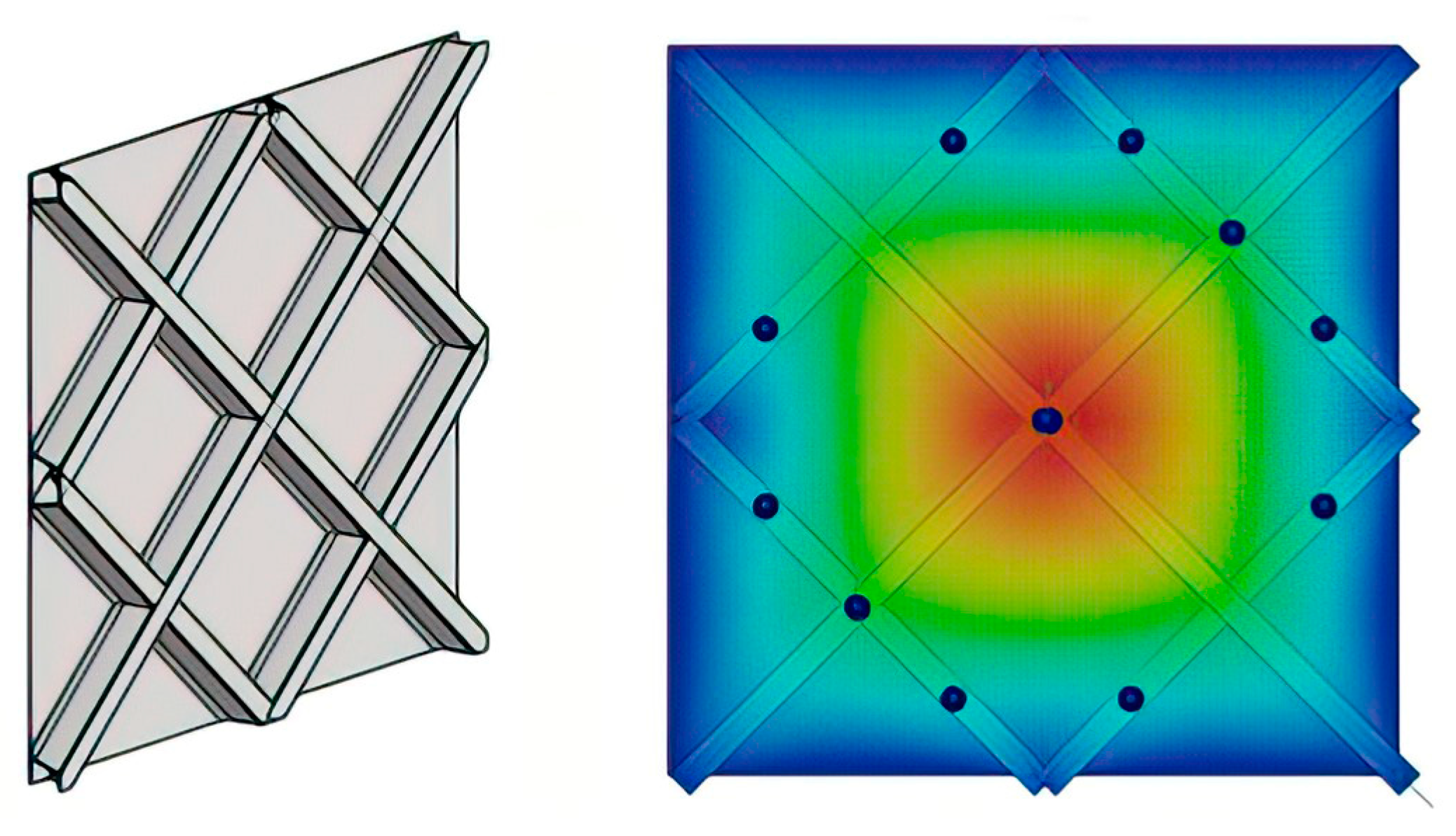
  • Finite element method (FEM) models were calibrated based on the data obtained from the tests in step 1, establishing the engineering constants for both the balsa core of the balsa sandwich panels and the thermoplastic core of the prototype panels;
  • FEM simulations of a large-scale three-point bending test were conducted on the Type B balsa sandwich panel (1150 × 565 × 47 mm), and FEM simulations were performed to design a prototype panel of comparable size and stiffness (1150 × 565 × 85 mm);
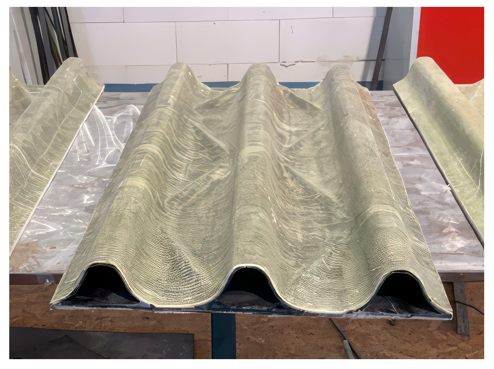
  • Two composite panels with thermoplastic cores (1150 × 565 × 85 mm) were manufactured, vacuum-bag-laminated with polyester resin and glass fibre, and then dispatched to the balsa sandwich panel testing laboratory;
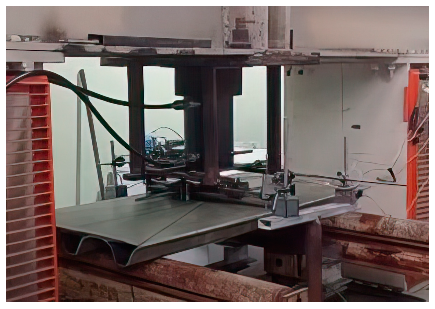
  • A large-scale three-point bending test was carried out on the Type B balsa sandwich panel (1150 × 565 × 47 mm), the FEM simulation results from step 3 were validated, and the overall stiffness of the balsa sandwich panels was redefined based on the test’s outcomes;
  • The thickness of the prototype panels was reduced to 78 mm to achieve the appropriate stiffness, two 1150 × 565 × 78 mm composite panels were produced (vacuum-bag-laminated with polyester resin and glass fibre), a large-scale three-point bending test was conducted on these newly optimised panels, and the accuracy of the FEM results from step 3 was confirmed.
The production of the panels sent to the balsa sandwich panel testing laboratory (step 4) was prioritised before the panel testing with the balsa core (step 5) to expedite the delivery process as much as possible. Therefore, the panels with a rib height of 85 mm were anticipated to demonstrate greater stiffness than those with a rib height of 78 mm (step 6). The primary findings from steps 1, 2, 5, and 6, alongside the relevant activities and conclusive insights, are summarised below.
Concerning the results reported below, it is essential to emphasise that the objective of these initial instrumental findings was not to carry out an exhaustive mechanical characterisation campaign but rather simply to obtain some reference parameters to guide further development in the approach to the morphological and structural design of the panels according to the technique described.

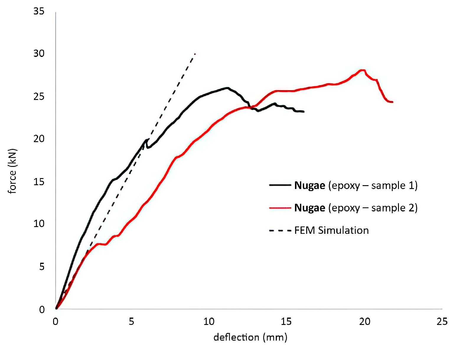
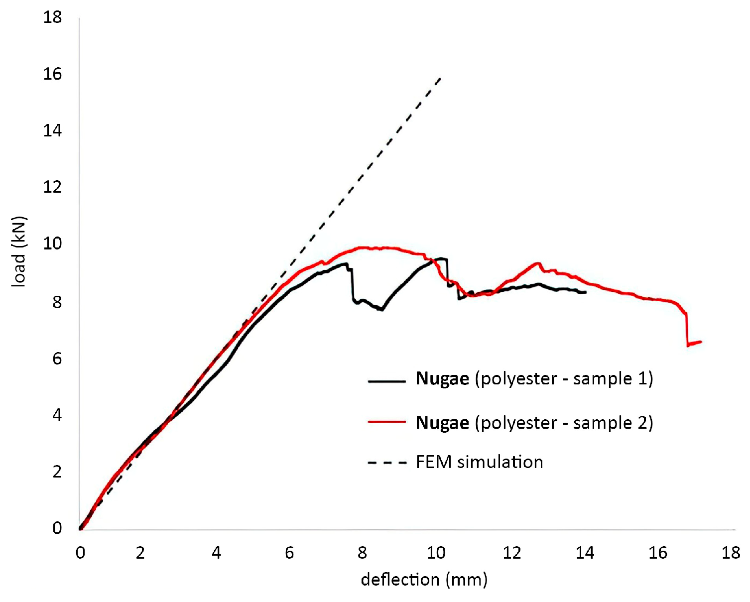
3.1.3. Test Findings and FEM Analysis for Small Specimens (Steps 1 and 2)

For the three-point bending assessments, three pairs of test pieces were prepared. The initial pair was sourced from one of the Type B balsa sandwich panels (Figure 7). Table 2 encapsulates the principal dimensions of the three specimen types. The thermoplastic core specimens were fabricated using 3D printing, featuring a hollow tubular configuration akin to the rib geometries of the ultimate panels (refer to Figure 6 and Figure 8). These four 3D-printed specimens, which are uniform with respect to the core’s design, underwent vacuum-bag lamination with two distinct resin types, employing varied methodologies:
  • Type 1. Polyester resin and glass fibre via a two-step vacuum-bag lamination process;
  • Type 2. Epoxy resin and glass fibre via a single-step vacuum-bag lamination.
The lamination techniques led to differing results: Type 2 specimens achieved a more significant volumetric proportion of glass fibre relative to resin (approximately 44%) than Type 1 specimens.
Per the norms for non-standard configurations, we set the span length to the specimen length minus 50 mm and the crosshead displacement speed to 6 mm/min.
The outcomes from the assessments conducted on the two Type B samples are depicted in Figure 9, showcasing the load–deflection curves. The failure mechanism was predominantly shear, leading to the cracking of the balsa core in both specimens. Sample 1 maintained its initial stiffness for most of the test, whereas sample 2 exhibited progressive skin delamination, resulting in reduced bending stiffness, as illustrated in Figure 10. The ultimate failure in both instances occurred under loads within the anticipated range based on the shear strength of the balsa.
To analyse these results, a comprehensive FEM model was developed for the specimen containing a balsa core. By adopting a linear elastic behaviour model for various composite materials and comparing it with experimental data, the average shear modulus G for the balsa core was deduced to be approximately 80 MPa. This value is in agreement with the literature’s values for materials exhibiting anisotropic properties. The load–deflection curve generated from the simulations using the calibrated FEM model is also shown in Figure 9, along with the experimental findings. This FEM model, with adjusted material parameters, was also applied to estimate the stiffness of a larger panel (1150 × 565 × 47 mm) with a balsa core under a three-point bending test. This stiffness value was subsequently used as a benchmark for designing a 3D-printed thermoplastic core panel in step 3.
Experimental data from tests on the remaining four specimens of both types (laminated with either epoxy or polyester) are presented in Figure 11 and Figure 12, respectively. Contrary to the balsa core specimens, the failure in the scaled-down Nugae rib models occurred in several distinct stages and was attributed to the complex shape and the interaction between the skin and the hollow thermoplastic 3D-printed core. Both epoxy and polyester specimens exhibited multiple failure modes with a gradual loss of stiffness, yet they continued to bear loads beyond the last significant failure event. The epoxy specimens demonstrated superior overall stiffness primarily due to having a thicker lamination than the polyester variants.
A detailed three-dimensional FEM model was similarly developed for the hollow specimens. The material parameters for the different layers constituting the laminated portion of the composite were meticulously determined based on the literature. For the core, the mechanical properties of the 3D-printed thermoplastic were considered.
The numerical results from the FEM simulations of the three-point bending tests were then juxtaposed with the experimental test data (as shown in Figure 11 and Figure 12). The load–deflection curves reveal that the FEM model successfully captured the mechanical behaviour of both specimen types, accounting for the variations in shear stiffness attributable to the differing resin-layer thicknesses.

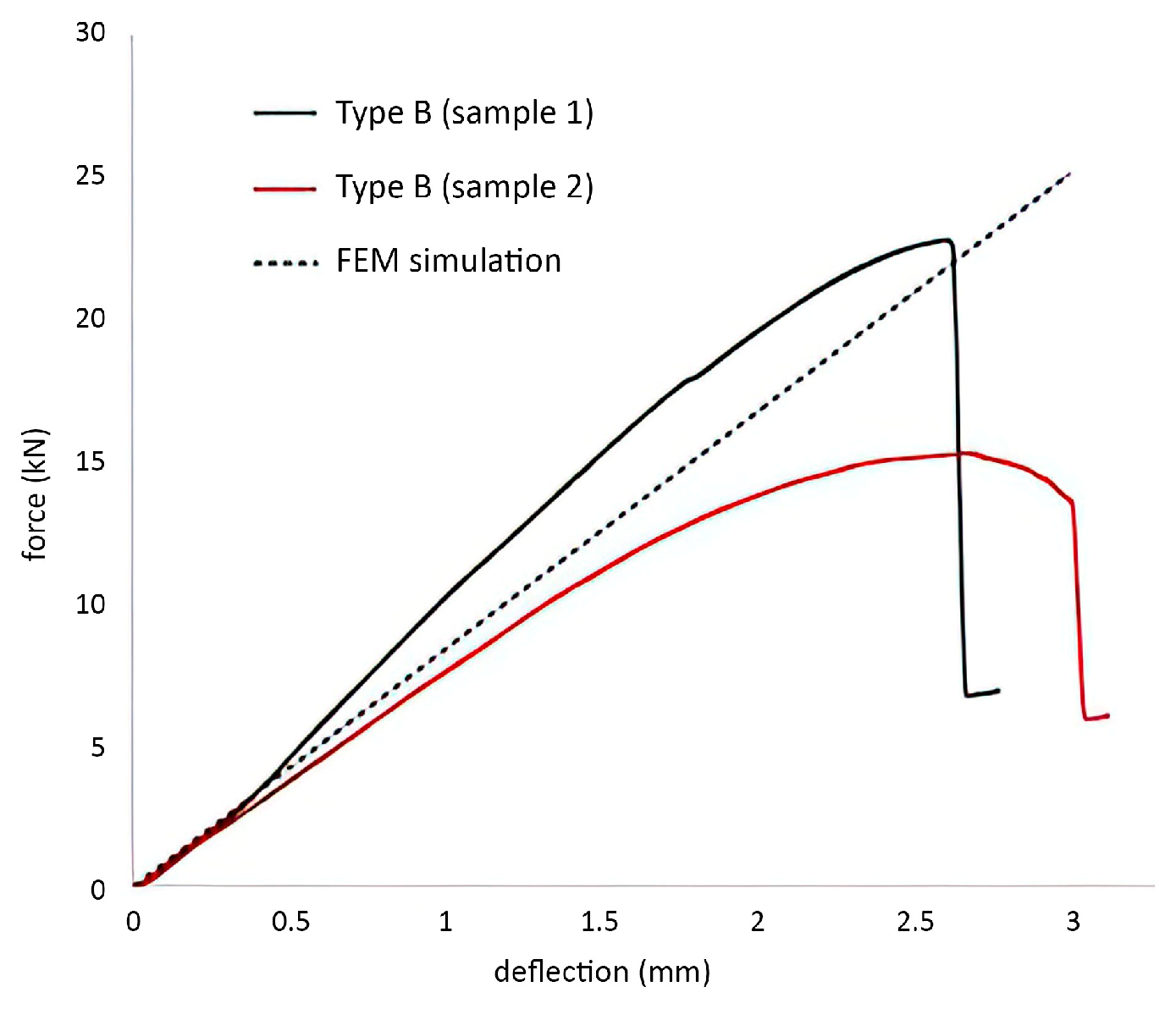
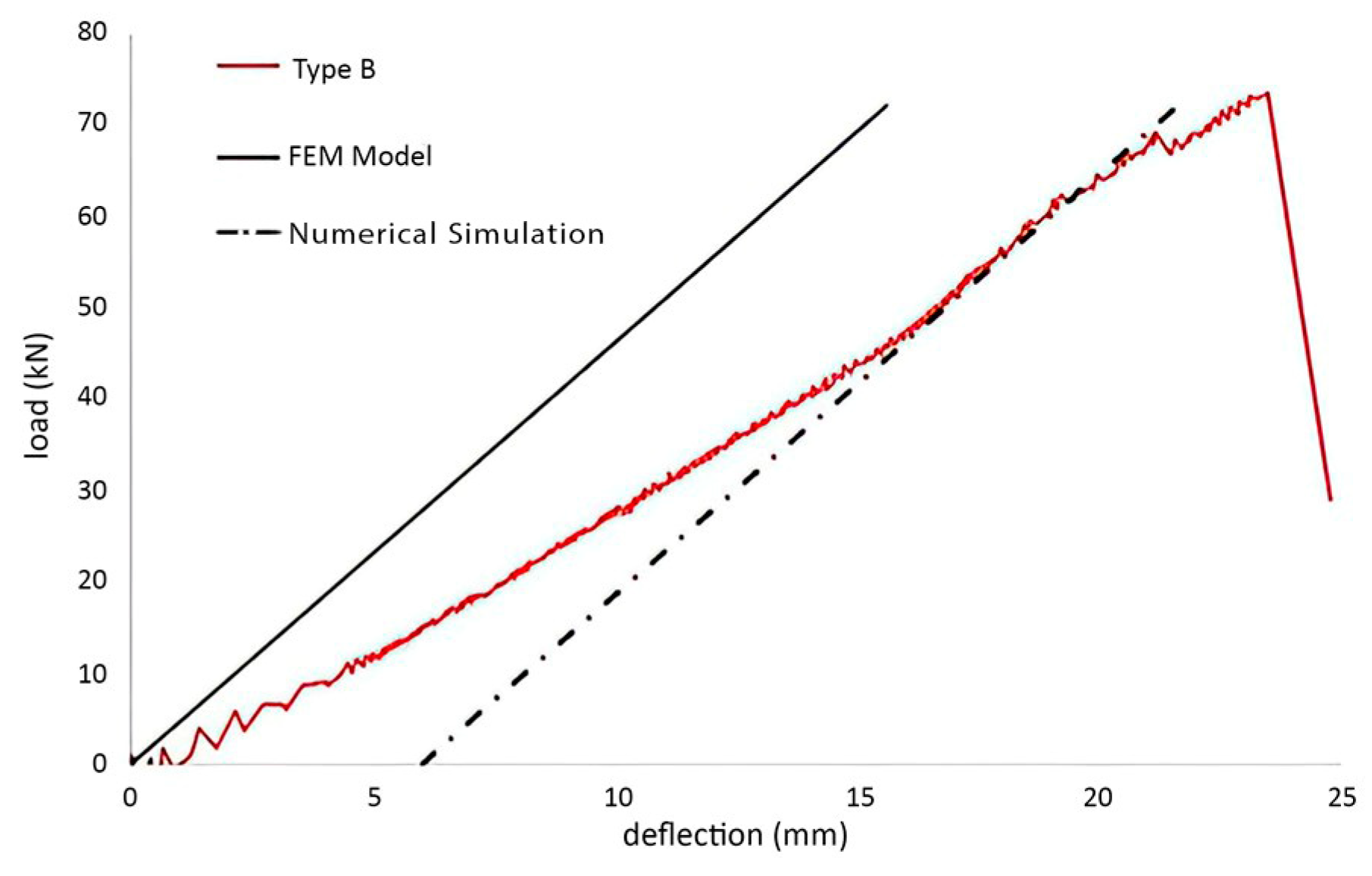
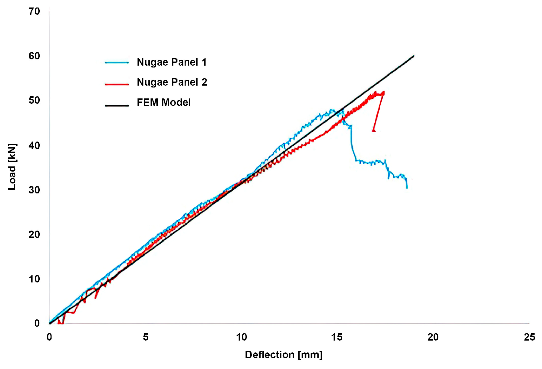
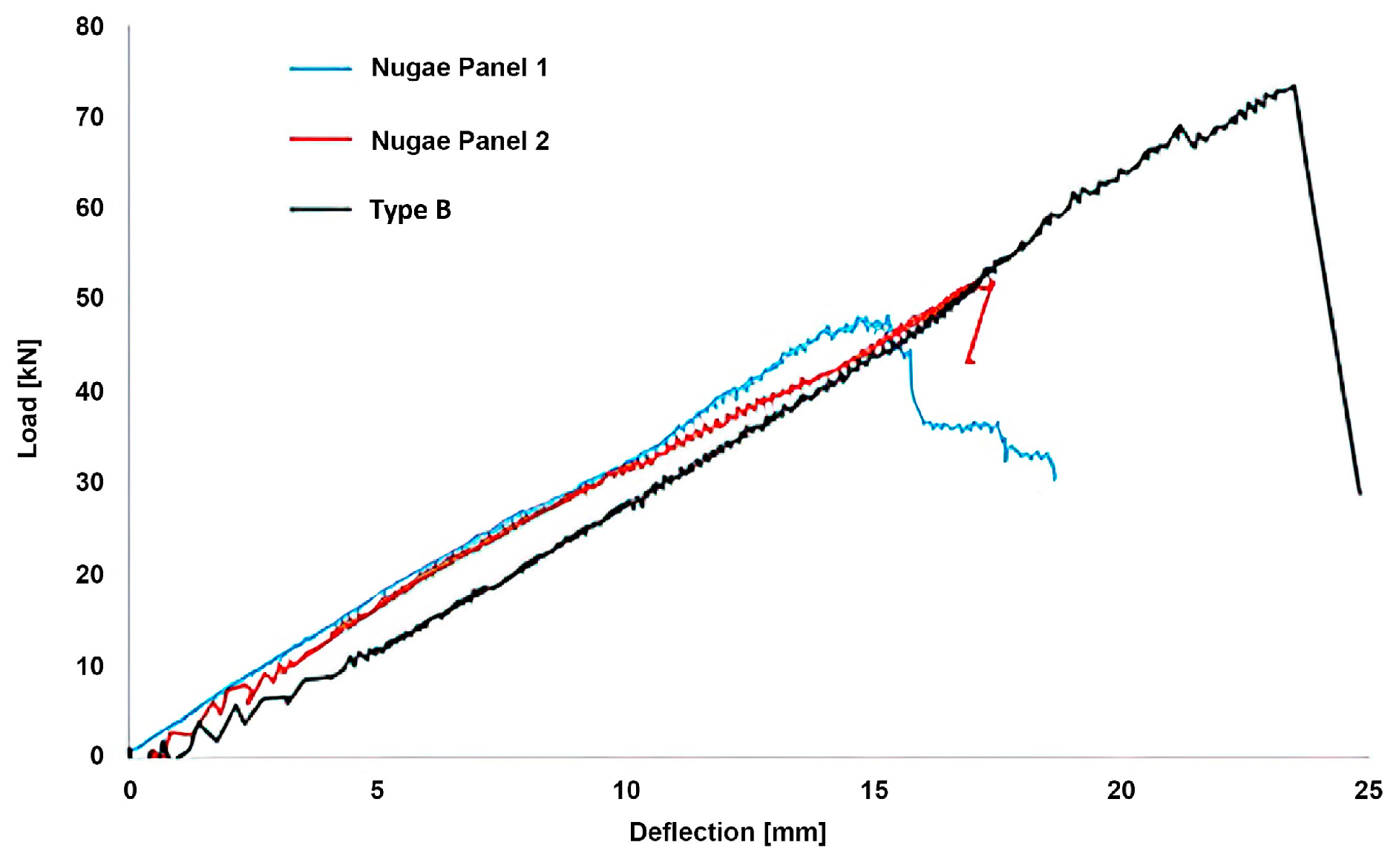
3.1.4. Test Results and FEM Modelling for Large Panels (Steps 5 and 6)

A three-point bending assessment was conducted on a full-sized Type B panel featuring an 850 mm span between the support points (Figure 13). Furthermore, a segment of fibreglass skin was removed from a comparable panel and measured to determine the actual glass volume fraction, approximately 46%. This figure aligns with the panel’s specified weight per unit area (around 27.5 kg/m2). The characteristics of the panel with the balsa core are compiled in Table 3.
The test results regarding the load–deflection curves are shown in Figure 14. Since the distance between the supports was longer than that on the smaller samples (but in the same proportion as the panel length), these latter results better represent the mechanical response of a beam since the influence of the shear stresses was less dominant compared to previous tests. The load–deflection curve simulated with the FEM model (which takes into account both the real layup and the elastic constants of the balsa core deduced throughout the previous tests) is also presented in Figure 14 as a comparison with the experimental results. For deflections of up to 16 mm, the panel’s stiffness was lower than that expected from numerical simulations. The stiffness aligns with the FEM result for more considerable deflections, probably due to a better fibre-load alignment as the woven fabric started to unwind.
Following the insights gained from these findings, the design of the rib-reinforced panel was revised using a FEM model. The redesigned panels feature ribs that were 10% lower than those initially produced. Consequently, two new panels were fabricated through 3D printing and vacuum-bag-laminated with polyester resin and glass fibre, optimising the glass volume fraction. The hollow core structure and selected layup strategy enabled us to maintain the weight per unit area within each panel’s 24–26 kg/m2 range. The details of these panels are documented in Table 4.
Subsequently, the two panels underwent three-point bending tests, mirroring the procedure used for the Type B panel (referenced in Figure 15). The experimental outcomes were then juxtaposed with the numerical predictions from the FEM model, as depicted in Figure 16. This comparison illustrates the congruence between the load–deflection curve derived from FEM simulations and empirical data. Furthermore, when contrasting these findings with those acquired from the small-scale rib specimens, it became apparent that the load–deflection relationship tended towards a more linear pattern under loading conditions, increasingly governed by bending rather than the shear.
A key takeaway (highlighted in Figure 17) is the successful fabrication of two composite panels (featuring a thermoplastic core) that match the stiffness of the Type B panel but with approximately 10% less mass. However, it is essential to note that the ultimate strength of the panels with a thermoplastic core was about 30% lower than that of panels with a balsa core, as shown in Figure 17.

3.1.5. Final Product Outcome

The described composite panels have the following properties:
  • Stiffness comparable to that of conventional panels;
  • Approximately 10% lighter than the reference panels (about 25 kg/m2 compared to 27.5 kg/m2);
  • Ultimate strength about 30% lower than that of the reference panels.

3.2. Case Study 2: RIB Windshield Design

3.2.1. Objective

In this windshield prototype, conceived and crafted for a RIB (rigid inflatable boat) by the Sicilian shipyard Noah Battelli, the primary objective is optimal protection for the boat driver during extended voyages without compromising the vessel’s style or aerodynamic performance. The solution called for a lightweight structure that is seamlessly integrated with the boat. The solution also maintained simplicity and adaptability and emphasised key features, such as ample windows and a suspended sunroof to shield against the sun during navigation.

3.2.2. Methodology

The design process of the windshield focused on different aspects:
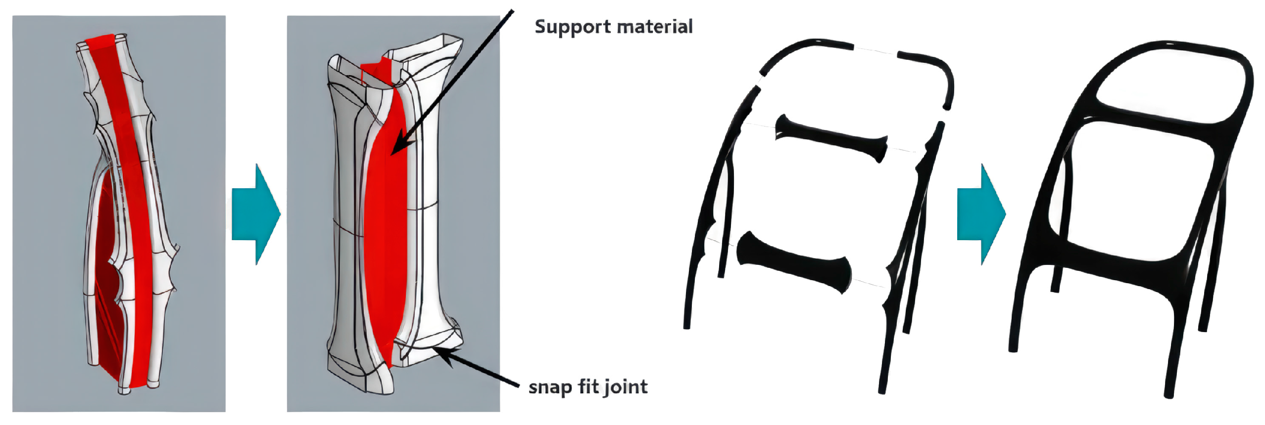
  • Topological optimisation. The design of the organic structure included a division into three segments. This design focuses on topological optimisation, ensuring the structure is ergonomic and fits seamlessly with the boat’s existing console. The design incorporates irregular and interconnected tubular forms, integrating carbon fibre for strength and lightness.
  • Milling of joints and eliminating support structures. The segments are designed with joints that allow them to fit together seamlessly (snap fit). These joints are milled for an optimal fit. The design process also eliminates the need for additional support flaps, which are standard in traditional AM methods.
  • Application of additional fixation to base. At the end of the printing process, additional fixation to the base was applied using thermoplastic glue. Subsequently, the piece was milled with a 1 mm-deep carving at each stage while maintaining a 10 mm connection to preserve the stability and integrity of the part. These connections were manually removed in a subsequent phase.
  • Preparation for single-element assembly (Figure 18). Although the structure is printed in three separate pieces, it is designed to be easily assembled into a single, cohesive unit. This modular approach allows for efficient printing and assembly.
  • Focus on innovative geometries. The design involves innovative geometries that enhance the aesthetic appeal and contribute to the structure’s aerodynamic efficiency and lightness.
  • Three-dimensional printing process. During printing, particular attention is given to support structures. These supports ensure stability during printing while being easy to remove afterwards, contributing to the final product’s overall lightness and clean finish.

3.2.3. Post-Printing Processes

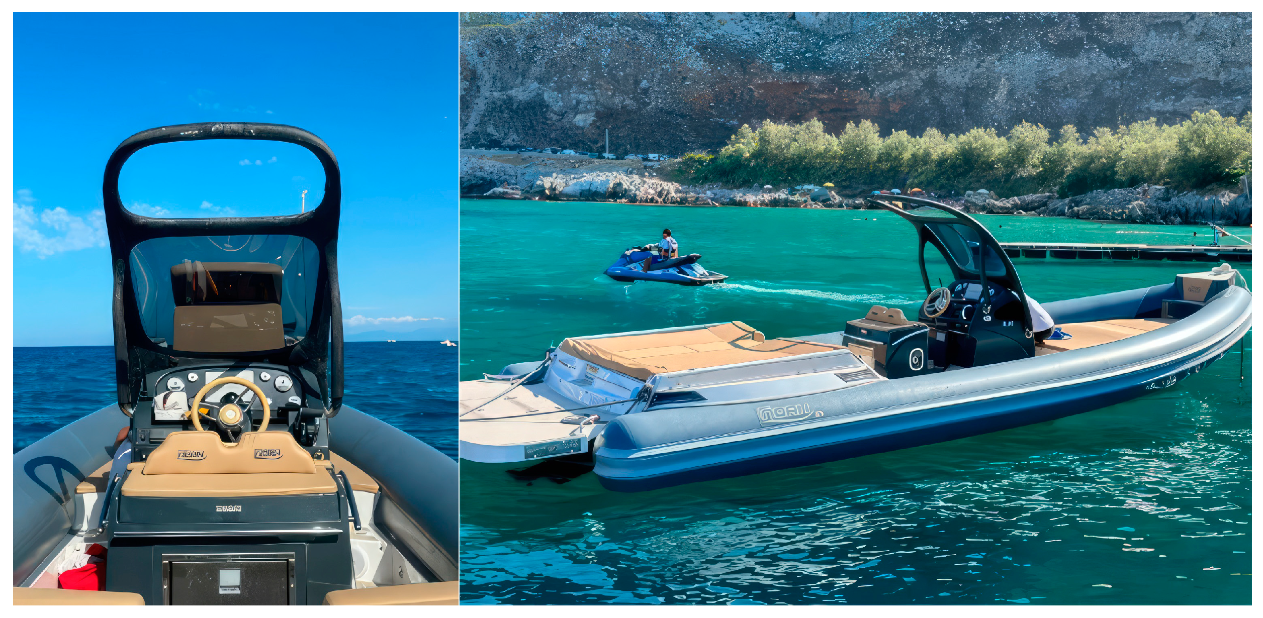
  • Lamination from the inside. As described above, the lamination step adds extra strength and weather resistance to the printed parts. The process involved inserting pre-impregnated carbon fibre sleeves around a tubular bag for internal laminating. Then, once inserted into the cavity using a probe, the sleeves were compacted against the 3D-printed part by inflating the sleeves to a pressure of 100 kPa.
  • Painting. The structure was painted, likely with marine-grade paint, to match the boat’s aesthetics and provide additional protection.
  • Assembly. The final step involved assembling the three printed parts into a single structure, achieving a seamless fit with the existing boat console.
  • Integration with the boat. The newly printed windshield was then integrated with the boat, protecting the elements without compromising style or aerodynamics.

3.2.4. Final Product Outcome

The parts (Figure 19) were 3D printed in two days, followed by a three-day resin-coating process. The overall weight of the assembly was 11 kg, with the 3D-printed part contributing 8 kg. The parts were tested over 150 h of navigation, which were divided as follows: 75 h at 28 knots and 75 h at variable speeds ranging from 4 to 28 knots. The parts demonstrated no structural compromise. This testing phase is crucial for assessing the durability and functionality of the newly designed boat windshield, especially under challenging marine conditions.

3.3. Case Study 3: Hardtop of 13 m RIB

3.3.1. Objective

This project aimed to create a distinctive and operational hardtop for a 13 m motorised RIB produced by Joy Marine and designed by architect Franco Gnessi. This endeavour presented several challenges due to the intricate nature of the product, requiring multiple moulds for production. Moreover, there was a constrained time frame to update the project, adding urgency to the boat’s completion. The objective was to produce a lightweight and hollow interior object, facilitating the passage of cables. The design needed to accommodate the boat’s complexity, substantial size, and curved form, and provide adequate rigidity and resistance. All these goals had to be achieved while maintaining a harmonious blend of style and aerodynamic efficiency.

3.3.2. Methodology

  • Design optimisation. The hardtop was designed with careful consideration of the boat’s specifications, particularly its curved and sinuous shape, to achieve seamless integration.
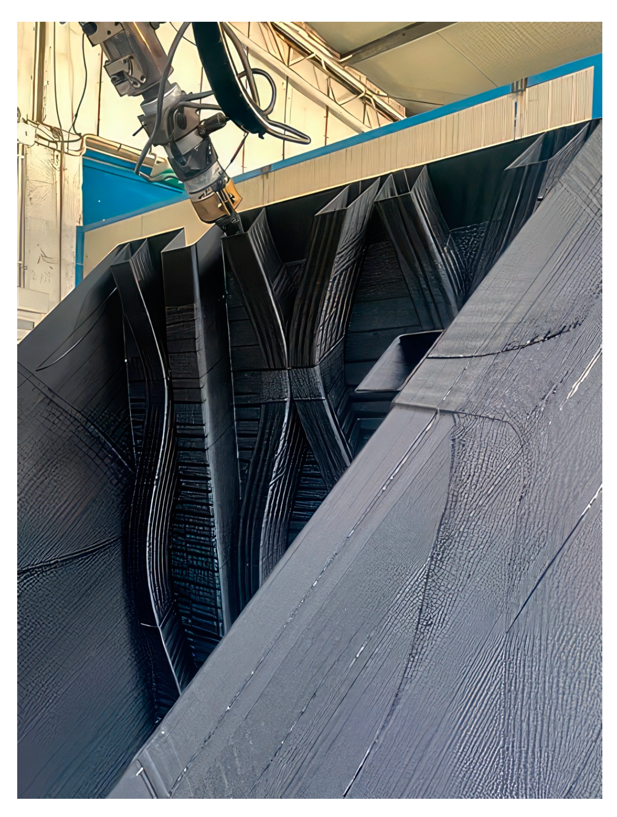
  • Segmentation and custom element printing. The complex design was segmented into manageable parts for efficient 3D printing and assembly. The segmentation of parts is visible in Figure 20.
  • Incorporating an iso-grid system. A patented iso-grid system was utilised to enhance structural integrity and stiffness, ensuring that the final product was lightweight yet robust.
  • Assembly system integration. These segments were assembled into one cohesive unit, wrapped with fibreglass, and then sanded and faired.

3.3.3. Final Product Outcome

Each segment of the hardtop was 3D printed over five days, allowing for precision in the complex details; the finished product amounted to 60 kg for a 40 m2 surface structure (Figure 21). The AM processes yielded a product that matched the original design well, offering high customisation and detail without moulds and reducing material usage. In addition, production was twice as fast compared to traditional milling methods. The boat was commercialised and tested in extensive and varied weather conditions, and no issues were detected.

4. Discussion

The presented study on 3D-printed structural panels revealed that they offer stiffness levels comparable to traditional panels while reducing the overall weight by approximately 10%. However, it is crucial to note that their ultimate strength is roughly 30% lower than that of conventional panels. This opens up the possibility of using these panels in maritime contexts where the priority is weight reduction rather than ultimate strength regarding serial-production boats.
It is worth noting that the significant bridging effect exhibited by the thermoplastic core suggests that the 3D-printed structures may be well suited for enduring fatigue loads without significant early damage. However, further investigations in this regard are necessary and will be the subject of already planned future studies. More stiffness and ultimate strength improvements can be implemented by incorporating unidirectional glass fibres aligned with the anticipated load directions. In addition, potential improvements can be achieved by optimising the rib aspect ratio and material layup.
The presented RIB windshield design exhibits promising outcomes, particularly excelling in efficiently producing lightweight components. This project employed advanced methodologies to craft a functional, aesthetically pleasing boat windshield tailored to specific preferences and needs. Tested rigorously in challenging sea conditions (i.e., reaching speeds of up to 28 knots for over 150 h), the design proved its reliability in various aspects:
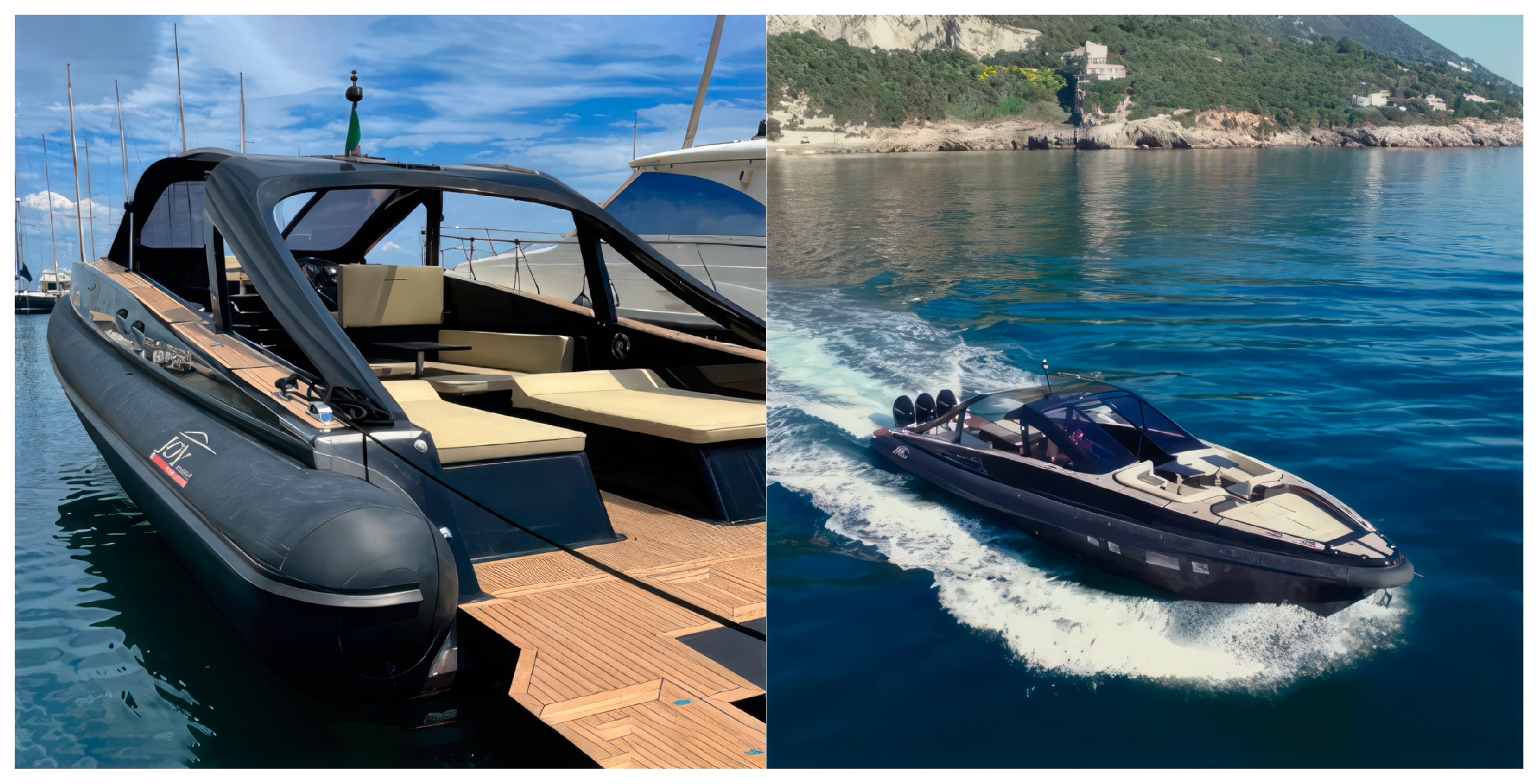
  • Durability assessment. The windshield demonstrated its structural integrity under stress, such as strong waves and wind pressure.
  • Performance analysis. Since the windshield was not compromised despite the rough testing conditions, qualities such as aerodynamics and stability at high speeds of the design were validated.
  • Shielding verification. The windshield provided a secure boating experience since it effectively protected the boat owner from elements such as splashing water and direct sunlight.
  • Longevity testing. The fact that the part was tested for an entire summer season demonstrated its ability to withstand prolonged exposure to various environmental factors, such as salt water, UV radiation, and temperature fluctuations.
The 13 m RIB’s hardtop demonstrates the achievement of a complex and large-scale design. This successful endeavour aligns seamlessly with the initial design goals and surpasses traditional speed and end-product quality methods. The hardtop is visually appealing and offers increased rigidity and resistance compared to its conventional counterparts. It is lighter, thus lowering the boat’s centre of gravity, improving its performance and stability, and simplifying installation. Incorporating an iso-grid system and advanced materials elevates the product’s durability and longevity. Environmental friendliness and economic efficiency are cornerstones of this project. Reducing material waste and eliminating moulds showcase a commitment to sustainability and add to the production process’s overall economic viability.
Regarding overall considerations, material studies exploring ways to improve composite formulations for 3D printing can drive further enhancements. Moreover, expanding mechanical testing to analyse behaviours such as buckling, impact resistance, and fatigue will generate data vital for certification. Additionally, it should be investigated whether different structural designs can enhance both stiffness and strength. Finally, studies directly comparing full-scale 3D-printed and traditionally constructed vessel components can provide insights into their feasibility at an industrial scale.

5. Conclusions

AM presents transformative potential for the maritime industry. The described new manufacturing method mirrors global trends and is at the forefront of adopting 3D printing for complete and weight-competitive vessel construction and spare part fabrication. The presented case studies demonstrate the feasibility of producing large-scale structures and essential components, marking a shift from traditional manufacturing methods. The prospects of additive techniques in maritime applications are promising, indicating the potential for constructing larger vessels and further innovations in the industry.
While AM offers benefits such as weight reduction, design flexibility, and environmental sustainability, this study also highlights the need for ongoing research and development, particularly in material innovation and scalability. The successful application in the presented maritime projects shows a significant step towards a more efficient, flexible, and environmentally conscious opportunity for industrial applications.

6. Patents

The presented technologies are based on patent n.102020000023260 by Nugae.
The invention pertains to methods for creating load-bearing structures in shell or slab form, such as boat hulls and aircraft structures, particularly fuselage structures, wing or tail structures, vehicle chassis, and subgroups. It also applies to structures like propeller blades and wind turbine rotors, generally featuring relatively thin-walled load-bearing structures, where structural strength and high lightness are required. Another potential application relates to moulds used in the manufacturing structures of the type mentioned above, particularly moulds for producing structures made of composite material. The invention is advantageous in producing large load-bearing structures in a shell or slab form, especially those requiring hydrodynamic or aerodynamic features. It addresses the limitations of traditional manufacturing methods by simplifying the process, allowing for intricate rib designs and ensuring a smooth exterior finish on the structure.

Author Contributions

Conceptualisation, A.R.; data curation, F.B.; funding acquisition, A.R.; investigation, F.B.; methodology, A.R.; supervision, A.R.; writing—original draft, F.B.; writing—review and editing, M.P. and A.R. All authors have read and agreed to the published version of the manuscript.

Funding

This research was funded by PNRR Made in Italy Circolare e Sostenibile (MICS)—Spoke 2, grant number PE_00000004. The APC was funded by the European Union (EU) and Ministero dell’Università e della Ricerca (MUR).

Data Availability Statement

Data are contained within the article.

Conflicts of Interest

Author Francesco Belvisi was employed by the company Nugae. The remaining authors declare that the research was conducted in the absence of any commercial or financial relationships that could be construed as a potential conflict of interest.

References

  1. Musio-Sale, M.; Nazzaro, P.L.; Peterson, E. Visions, concepts, and applications in additive manufacturing for yacht design. Adv. Intell. Syst. Comput. 2020, 975, 401–410. [Google Scholar] [CrossRef] [PubMed]
  2. Peterson, E. Technical challenges to adopting large-scale additive manufacturing for the production of yacht hulls. In Proceedings of the 3rd International Conference on Human Systems Engineering and Design (IHSED2020): Future Trends and Applications, Pula, Croatia, 22–24 September 2020. [Google Scholar] [CrossRef]
  3. Taş, Ş.O.; Şener, B. The use of additive manufacturing in maritime industry. Int. J. Eng. Trends Technol. 2019, 67, 47–51. [Google Scholar] [CrossRef]
  4. Gibson, I.; Rosen, D.; Stucker, B. Additive Manufacturing Technologies: 3D Printing, Rapid Prototyping, and Direct Digital Manufacturing, 2nd ed.; Springer: Berlin/Heidelberg, Germany, 2015. [Google Scholar] [CrossRef]
  5. Khajavi, S.H.; Partanen, J.; Holmström, J. Additive manufacturing in the spare parts supply chain. Comput. Ind. 2014, 65, 50–63. [Google Scholar] [CrossRef]
  6. Attaran, M. The rise of 3-D Printing: The advantages of additive manufacturing over traditional manufacturing. Bus. Horiz. 2017, 60, 677–688. [Google Scholar] [CrossRef]
  7. Weller, C.; Kleer, R.; Piller, F.T. Economic implications of 3D Printing: Market structure models in light of additive manufacturing revisited. Int. J. Prod. Econ. 2015, 164, 43–56. [Google Scholar] [CrossRef]
  8. De la Peña Zarzuelo, I.; Freire Soeane, M.J.; López Bermúdez, B. Industry 4.0 in the port and maritime industry: A literature review. J. Ind. Inf. Integr. 2020, 20, 100173. [Google Scholar] [CrossRef]
  9. Hao, L.; Raymond, D.; Strano, G.; Dadbakhsh, S. Enhancing the Sustainability of Additive Manufacturing. In Proceedings of the 5th International Conference on Responsive Manufacturing-Green Manufacturing, ICRM 2010, Ningbo, China, 11–13 January 2010. [Google Scholar] [CrossRef]
  10. Ziółkowski, M.; Dyl, T. Possible applications of additive manufacturing technologies in shipbuilding: A review. Machines 2020, 8, 84. [Google Scholar] [CrossRef]
  11. Superfici Prints Smart Wheel. Available online: https://www.proboat.com/2020/09/superfici-prints-smart-wheel/ (accessed on 1 October 2023).
  12. Navigating the Best Examples of 3D Printed Boats. Available online: https://www.3dnatives.com/en/3d-printed-boats-300320214/ (accessed on 21 September 2023).
  13. Can 3D Printing Transform the Way Boats Are Designed and Built? Available online: https://www.boatinternational.com/yachts/yacht-design/is-3d-printing-the-future-of-yacht-design (accessed on 4 October 2023).
  14. Peterson, E. Recent innovations in additive manufacturing for marine vessels. Marit. Technol. Res. 2022, 4, 257491. [Google Scholar] [CrossRef]
  15. World’s First 3D Printed Water Taxi Is Also Largest 3D Printed Boat. Available online: https://www.3dnatives.com/en/3d-printed-water-taxi-is-worlds-largest-3d-printed-boat-201120234/ (accessed on 20 February 2024).
  16. Brun, A.; Karaosman, H. Customer influence on supply chain management strategies: An exploratory investigation in the yacht Industry. Bus. Process Manag. J. 2019, 25, 288–306. [Google Scholar] [CrossRef]
  17. Ponche, R.; Hascoet, J.Y.; Kerbrat, O.; Mognol, P. A new global approach to design for additive manufacturing. In Additive Manufacturing Handbook: Product Development for the Defense Industry; Badiru, A.B., Valencia, V.V., Liu, D., Eds.; CRC Press: Boca Raton, FL, USA, 2017; pp. 169–186. [Google Scholar] [CrossRef]
  18. Kostidi, E.; Nikitakos, N. Exploring the potential of 3D Printing of the spare parts supply chain in the maritime industry. In Proceedings of the 12th International Conference on Marine Navigation and Safety of Sea Transportation (TransNav 2017), Gdynia, Poland, 21–23 June 2017. [Google Scholar]
  19. Ford, P.; Dean, L. Additive manufacturing in product design education: Out with the old in and in with the new? In Proceedings of the E&PDE 2013, the 15th International Conference on Engineering and Product Design Education, Dublin, Ireland, 5–6 September 2013. [Google Scholar]
  20. 3D Printing in Boat Manufacturing. Available online: https://ceadgroup.com/3d-printing-in-boat-manufacturing/ (accessed on 23 April 2024).
  21. Post, B.K.; Chesser, P.C.; Lind, R.F.; Roschli, A.; Love, L.J.; Gaul, K.T.; Sallas, M.; Blue, F.; Wu, S. Using big area additive manufacturing to directly manufacture a boat hull mould. Virtual Phys. Prototyp. 2019, 14, 123–129. [Google Scholar] [CrossRef]
Figure 1. The Nugae extruder.
Jmse 12 00918 g001
Figure 2. The Nugae extruder, tool-change system, and milling system on Fanuc M8001a.
Jmse 12 00918 g002
Figure 3. Examples of possible ribbing strategies explored in the patent for a single line and no infill pattern.
Jmse 12 00918 g003
Figure 4. The suggested alternative boatbuilding process.
Jmse 12 00918 g004
Figure 5. The 3D printing of a panel with rectangular-section sinusoidal ribs.
Jmse 12 00918 g005
Figure 6. Panel with dimensions of 1000 × 1000 × 60 mm optimised for hydrostatic loads (left) and a contour plot from the finite element method (FEM) simulation (right).
Jmse 12 00918 g006
Figure 7. Testing rig for the three-point bending test of a standard panel.
Jmse 12 00918 g007
Figure 8. Nugae structural composite panel optimised for a large-scale three-point bending test (1150 × 565 × 85 mm).
Jmse 12 00918 g008
Figure 9. Three-point bending test results for standard sandwich panel Type B samples 1 and 2, along with simulation.
Jmse 12 00918 g009
Figure 10. Skin detachment on Type B sample 2.
Jmse 12 00918 g010
Figure 11. Three-point bending test results for Nugae epoxy samples along with FEM simulation.
Jmse 12 00918 g011
Figure 12. Three-point bending test results for Nugae polyester samples along with FEM simulation.
Jmse 12 00918 g012
Figure 13. Testing rig for the three-point bending test (Type B panel).
Jmse 12 00918 g013
Figure 14. Three-point bending test results for the Type B panel along with FEM simulation.
Jmse 12 00918 g014
Figure 15. Testing rig for three-point bending test (Nugae panels).
Jmse 12 00918 g015
Figure 16. Three-point bending test results for Nugae panels along with FEM simulation.
Jmse 12 00918 g016
Figure 17. Three-point bending test results for Nugae panels and Type B panels.
Jmse 12 00918 g017
Figure 18. Assembly scheme of RIB windshield.
Jmse 12 00918 g018
Figure 19. Final product mounted on the RIB.
Jmse 12 00918 g019
Figure 20. Production of the RIB hardtop.
Jmse 12 00918 g020
Figure 21. Three-dimensional-printed hardtop mounted on the RIB.
Jmse 12 00918 g021
Table 1. Technical general specifications of tested materials.
MaterialTensile Strength [MPa]Flexural Strength [MPa]Flexural Strength [kJ/m2]Heat Deflection Temperature [°C]Max Water Absorption [%]Ultraviolet (UV) Resistance
PLA60952.557.50.25Low
ASA-PC100115251050.35High
ABS428016980.6Moderate
PA 6690135402551.3Moderate
PA 1252.560701650.25High
PC6590801400.15High
Table 2. Geometrical dimensions of the three different couples of specimens.
Specimen TypeQuantityLength [mm]Width [mm]Thickness [mm]
Type B225010047
Type 1225010078
Type 2225010078
Table 3. Data for Type B panel.
NumberLength [mm]Width [mm]Thickness [mm]Weight [kg/m2]
111505654727.5
Table 4. Data for the Type 2 Nugae panel.
QuantityLength [mm]Width [mm]Ribs Thickness [mm]Ribs Width [mm]Weight [kg/m2]
211505657810824–26
Disclaimer/Publisher’s Note: The statements, opinions and data contained in all publications are solely those of the individual author(s) and contributor(s) and not of MDPI and/or the editor(s). MDPI and/or the editor(s) disclaim responsibility for any injury to people or property resulting from any ideas, methods, instructions or products referred to in the content.

