Abstract
Offshore structures and ships can be progressively damaged due to repeated mass impacts induced by contacts with ships, ice floes, and dropped and/or floating other objects while in service. This paper aims to predict the residual deflection evolution of the marine structures under such impact repetitions. The side hull structures of the general ice-class vessels were selected for this study. The numerical simulations were performed to predict the deflection response of repeatedly impacted stiffened plates by using the software package Abaqus 6.13. For the simulations, the strain hardening of the relevant ice-class steel grade was adopted using the proposed constitutive equations, and the strain-rate hardening effects were taken into account by employing the existing formulations. The developed numerical model was substantiated against tests available in the open literature. Based on the validated model, a parametric study on various stiffened plates was performed. The evolution of the residual deflection of the repeatedly impacted plates with actual scantlings and various impact scenarios was investigated. A practical formula for the prediction of the residual deflection evolution of the plates under repeated mass impacts was proposed based on the regression analysis of the parametric study results. The reliability and accuracy of the proposed formula were confirmed through comparisons with numerical simulations and existing analytical formulations. It is expected that the proposed formula can be efficiently employed as a quick-hand tool for the reliable prediction of the residual deflection evolution incurred by repeated mass impacts.
1. Introduction
While in service, marine engineering structures, including offshore structures and ships, are exposed to various types of repeated loads, including repeated mass impacts induced by contacts with other objects (floating objects, dropped objects, and/or ice floes…) and repeated impulsive pressures arising from slamming, sloshing, and green water. Such repeated impacts can damage the structure progressively, possibly leading to the loss of the crew’s life and property. As an example, the damages of the repeatedly impacted marine structures due to noticed ice collisions can be found in Figure 1. The prediction of such damage to structures has become an essential task for structural design against repeated impacts. This paper focuses on the prediction of the residual deformation evolution of the repeatedly mass-impacted plates with actual scantling used in marine structures.

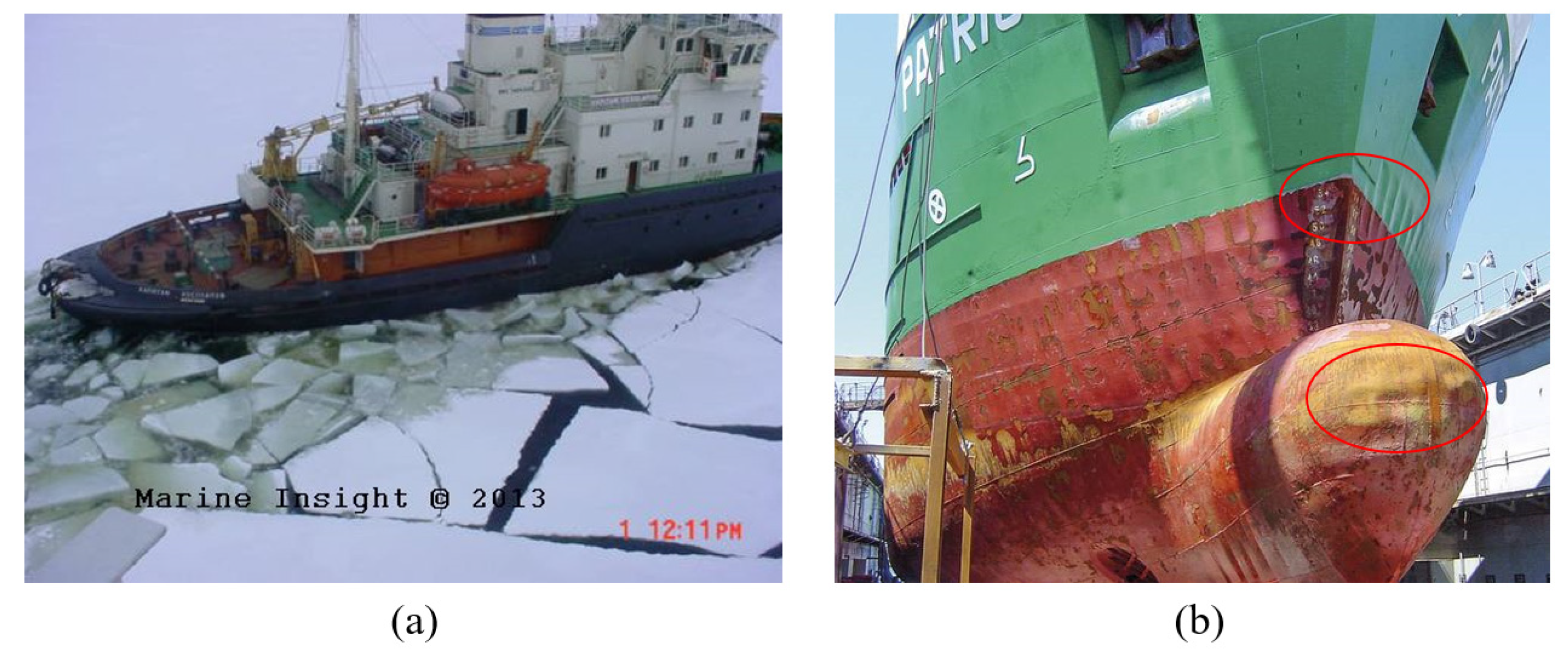
Figure 1.
(a) A ship on ice-covered sea and (b) damages to MV Patriot’s hull (see the red circles) due to repeated ice floe impacts.
Many studies have focused on the plastic response of simple structural components to repeated mass impacts [1,2,3,4,5,6,7,8,9,10,11,12,13,14,15,16,17,18,19,20,21,22,23]. Zhu and Faulkner [1] experimentally investigated the structural responses of clamped unstiffened plates under repeated impacts, in which steel and aluminum alloys were used for the testing plates, and they also proposed a theoretical method for the estimation of damage extents. Later, the repeated impact response of a clamped square and circular plates was studied experimentally by Huang et al. [2], and the conditions for the pseudo-shakedown state occurrence, which was first introduced by Jones [24], were discussed accordingly. By utilizing the theoretical analysis for repeated impacts from the previous studies (i.e., not retaining the masses) reported by Zhu and Faulkner [1], Jones [4] studied the effect of the remaining masses on a plate surface after each impact on the accumulation of structural damage, and the phenomenon of the pseudo-shakedown was examined accordingly.
Unlike the previous studies that considered room temperature only when evaluating the effect of load repetition, Cho et al. [5] explored the plastic response of steel beams to repeated mass impacts, considering low-temperature effects by several tests and numerical simulations. Truong et al. [6,7] extended the previous study [5] by considering various structure configurations (beams, grillages), materials, and striking body shapes. Consequently, a discussion on the effects of repeated impacts and a low temperature with more realistic impact conditions, structures, and material types on structural impact response was reported. Zhu et al. [8] performed several repeated impact tests to examine the deflection accumulation of the small-scaled steel stiffened plates, and an analytical method was proposed and validated with simulations. Later, in a series investigating the repeated impact response, several repeated impact tests on aluminum foam sandwich plates were further conducted by Zhu et al. [9] and Guo et al. [10,11], in which the effect of a low temperature was explored by Zhu et al. [9].
Duan et al. [12] and Zeng et al. [13] investigated the behavior of circular aluminum alloy plates with initial small cracks to repeated mass impacts and the effect of the crack size (depth and length) on the impact response of the plate was discussed based on only the numerical and experimental results. They concluded that the effect of surface cracks on the structural response was considerable. Robbins [14] conducted repeated mass rigid impacts on the steel stiffened plate of a navy ship, and numerical simulations were performed for various impact scenarios. By carrying out a series of repeated impact tests, Zhang et al. [15] studied the behavior and energy absorption of honeycomb sandwich panels made of aluminum alloys subjected to repeated impacts; they also performed numerical simulations to evaluate the accumulation processes of the plastic deformation of the tested models.
He and Guedes Soares [16,17,18,22] and He et al. [20] presented investigation results of the repeated impact response of small structural components, i.e., beams and plates, in which the pseudo-shakedown state was evaluated based on the experimental and numerical simulation results. Unlike the usage of the rigid striker in studying the repeated mass impact response in the previous studies, Cai et al. [19] adopted a deformable striker made of laboratory-made ice blocks to examine the behaviors of steel plates subjected to repeated ice impacts; with consideration for the crushable and failure behavior of the ice striker, the effect of the rigidity level of the striking body on the structural response was discussed. Based on the previous studies [9], Zhu et al. [21] also performed further repeated impact tests on the unstiffened steel plate with different indenter shapes, and the effect of the indenter shape on the pseudo-shakedown of the tested plates was investigated experimentally and theoretically. Recently, Xu et al. [23] proposed a simplified method for the prediction of the deformations of the small stiffened steel plates having initial cracks due to repeated impacts; the effect of the initial cracks on the impact resistance is examined through numerical simulations and experiments.
It is apparent from the above-mentioned survey that studies on the prediction of the dynamic response of structures under repeated mass impacts include experiments, theoretical investigations, and simulations. Nevertheless, in most of those cases, the structural analysis models considered were small and even, if not representative of full-impact loadings as collisions arising from contact with ice floes or contact with attendant service vessels; in fact, actual impacts are characterized by the heavy mass of a striking body, which is considerable with respect to the structural components. As a result, the existing methods either seem inefficient or may not directly be adopted for design purposes against such actual impact loads. Moreover, thanks to its simplicity, the analytical method is widely used to predict the extent of damage to repeatedly impacted structures. Nevertheless, the prediction by the analytical method is less accurate due to many assumptions for simplification [4,6,8,23].
In an earlier study, regarding the repeated impulsive pressures induced by slamming, Truong et al. [25] proposed several empirical formulae to predict the damage extents of steel plates used for marine vessels. However, the damages to the structures resulting from the repeated impulsive loads were, in fact, significantly different from those caused by the repeated mass impacts; unlike the damages due to slamming loads, the deformation is highly local by the point load of mass impacts, which is a distinctive feature of collision events. It is evident that though these formulae are useful in designing marine structures against slamming, they would not be suitable for the case of repeated mass impacts due to differences in those two types of loading characteristic consequences. Therefore, it was decided to propose simple yet accurate formulations for the reliable prediction of the residual deflection of stiffened steel plates having actual scantlings under repeated mass impacts.
In this study, a practical approach for the prediction of the residual deformation of stiffened steel plates due to repeated mass impacts, which can be efficiently employed for the structural design, is proposed. For this, the plastic deflection response of stiffened plates having actual scantlings used in marine applications under repeated mass impacts is investigated. Since only a few experimental data of the deformation for such actual structures are available, numerical simulations are adopted to generate the repeated impact response deformation of the stiffened plates. The validity of the numerical analysis model is confirmed through a comparison with the relevant published test data. A parametric study is performed on various plate scantlings to predict the structural deformation considering the main structure design parameters and mass impact loading conditions. Finally, an empirical formula is derived to predict the residual deflection evolution of the steel plate structures due to repeated mass impacts. To the best authors’ knowledge, it seems that no formulation for the prediction of the plastic damage evolution of stiffened steel plates with actual scantlings due to such repeated impacts has been introduced so far. It is expected that the formula proposed in this study will be efficiently employed as a quick tool for the prediction of residual deflection evolution incurred from repeated impacts.
This paper proceeds as follows. Section 2 describes the methodology for the prediction of the residual deflection of marine-graded stiffened steel plates due to repeated mass impacts; the main parameters are also presented in this section for the parametric study. Section 3 presents the validation of the numerical analysis model by comparison with relevant test data. In Section 4, typical numerical results obtained from the parametric study for the dynamic response of the repeatedly impacted steel plates having actual scantlings used in ice-class vessels are described. Section 5 illustrates the proposed formula for the prediction of the residual deflection evolution of stiffened steel plates under repeated mass impacts. Finally, a summary of the main findings of the study and anticipative future work are given in Section 6.
2. Methodology
2.1. Selection of Stiffened Plates and Striking Object
In this study, various stiffened steel plates which have actual scantlings of a hull’s side of ice-class vessels are selected for rigorous parametric studies, and their configuration is indicated in Figure 2. The assumption that strong bulkheads or girders surround the type of unidirectionally stiffened plate is considered. Here, each analyzing plate model was generated from the actual range of the design parameters of the aspect ratio α, plate slenderness ratio β, and column slenderness ratio λ, as defined in Equations (1)–(6), where a, b, and tp are the length, stiffener spacing, and thickness of the stiffened plate, respectively, I is the inertia moment of a stiffener with its attached plating, z0 is the distance between neutral axis and outer surface of plates–tiffener combination, A is cross-sectional area of stiffener with attached plating, σY is the yield strength, and E is Young’s modulus. The selected range of α was 5 to 10, and the ranges of β and λ are 0.418 to 2.607 and 0.127 to 0.444, respectively. The scantlings of the stiffened plates applied for the parametric study are generally similar to what were adopted by Daley and Kim [26]. The configuration of the stiffened plates is indicated in Table 1.
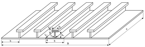
Figure 2.
Configuration of a stiffened plate with 6 stiffeners adopted in the parametric study.

Table 1.
Geometry of the stiffened plates and selected load scenarios.
It is noted that the striking body, in reality, can sometimes be damaged during collision events. However, for simplicity and conservativeness, a rigid body is considered in this study. In addition, considering possible extreme loading cases, the rigid striker’s header shape is assumed to be the semi-sphere with three cases of the diameter Ds = 0.4 m, 0.8 m, and 1.2 m. The initial impact velocity (V0) is selected in a range of 3.0 m/s to 6.0 m/s, corresponding to the actual velocity of marine vessels at the impact movement that occurred. To achieve severe plastic deformation, sufficient impact energy should be defined, in which the mass of the striker (Ms) is chosen from 10 tons to 15 tons.
2.2. Finite Element Modeling
The finite element (FE) software package Abaqus 6.13 is utilized for the modeling and analysis. The FE model contains two components: a stiffened plate and a striker, as displayed in Figure 3, in which the former is uniformly meshed with the shell element with reduced integration and hourglassing control (S4R). The optimum mesh size with an element’s edge length of twice the plating thickness, regardless of the plate dimensions, is sufficient for capturing local and global deformations of the impacted plate. Note that using this mesh size is also in line with the observations of other scholars [25,27]. The striker is modeled with rigid elements (R3D4) from the Abaqus 6.13 library.
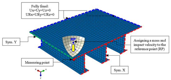
Figure 3.
A quarter FE model of a stiffened plate under repeated mass impacts (Sym. denotes symmetric).
The boundary conditions of the stiffened plates are assumed to be full clamping, marked with the dash-line in blue, as indicated in Figure 3. Owing to its symmetry condition, a quarter FE model is adopted in order to reduce computation time and save resources. The mass and initial impact velocity of the striker are assigned to the referent point (RP) (see Figure 3). The striker is allowed to freely move in the vertical translation only.
The coefficient of friction for the contact between the stiffened plate and the striker is assumed as 0.3 to account for the slipping between two bodies [6,28,29].
2.3. Definition of Material Properties
High-tensile steel (HTS) with a yield strength of 360 MPa, which is commonly used in a range of ice-class marine structures from IACS PC2 to PC4 [26], is used in this study. For simplicity, the same material is assumed for both the plate and the stiffeners. The mechanical properties of the material are listed in Table 2. The structural response involving large plastic deformations depends on the definition of plastic behavior including strain-hardening and strain-rate hardening models [30]. To realistically reflect the deformation of the impacted plate, the strain hardening model is herein adopted. To do this, the equations proposed by Cho et al. [31] are successfully adopted for constructing the corresponding parameters of the engineering stress–strain curve [25], as in Equations (7)–(9), where σT is the ultimate stress, εT is the ultimate strain, εHS is the hardening start strain, as follows:
Table 2.
Mechanical properties of stiffened plate material adopted in the present parametric study.
Next, the resulting engineering values are converted to the true stress–strain data using Equations (10) and (11), where σe is the engineering stress, σtr is the true stress, εe is the engineering strain, and εtr is the true strain:
Substituting the calculated true stress–strain values into Equations (12)–(16) [31], the relation of true stress and true strain can be formed [7].
where σHS,tr and σT,tr are the true values for the hardening start stress and the ultimate stress, respectively, and εHS,tr and εT,tr are the true hardening start strain and true ultimate strain, respectively. Additionally, for the numerical model, the true plastic strain value should be introduced, which is calculated by Equation (17). The calculated true stress–plastic strain curve adopted in this study is shown in Figure 4.
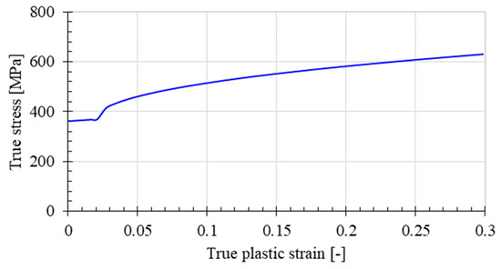
Figure 4.
The true stress–plastic strain curve applied to the current numerical simulations.
To take account for the strain rate effect, Equation (18), proposed by Cowper–Symonds [32], is adopted, where σYD is the dynamic yield stress and is the strain rate. The constants D and q therein are reasonably assumed as 3200/s and 5, respectively, for high-tensile steel material [7]. In this study, no fracture criterion is defined because only the plastic deflection mode is considered.
2.4. Definition of Repeated Impact Scenario
The repeated impact loadings are defined by multiple steps, in which identical impact energy (the remaining impact velocity and mass) is applied to each impact event. In particular, after the completion of the first impact simulation with the permanent stage, the same mass and velocity are re-introduced for the striker, and the simulation of the next impact event is started. The residual stresses and strains resulting from the previous impacts are preserved as the initial state of the model for the currently restarted analyses. Each stiffened plate is repeatedly loaded with five identical kinetic energies. With the above-noted impact energies, i.e., the striker velocity and mass and scantlings mentioned above, 192 cases are analyzed. The duration time of each impact simulation is set as 0.1 s to sufficiently capture the peak response and the permanent state of the impacted stiffened plate.
3. Repeated Mass Impact Tests on Structural Components for Validation
Numerous experimental studies on the effect of load repetition induced by slamming or collisions on the response of marine structural components have been performed. Therein, only a few repeated impact test data for stiffened plates with actual scantlings have been reported; these test data would be useful for the validation purposes of other methods such as analytical and numerical methods for the prediction of the residual deflection of marine structures subjected to repeated impacts. In this study, therefore, the results of the repeated rigid mass impact tests on large-scale stiffened steel plates conducted by Robbins [14] are employed to validate the current numerical analysis models. The experimental conditions are reflected in the numerical analyses, and the residual deflection data measured at the center of the plates, i.e., the maximum residual deflection, are utilized for the validations.
3.1. Brief Description of Repeated Mass Impact Tests
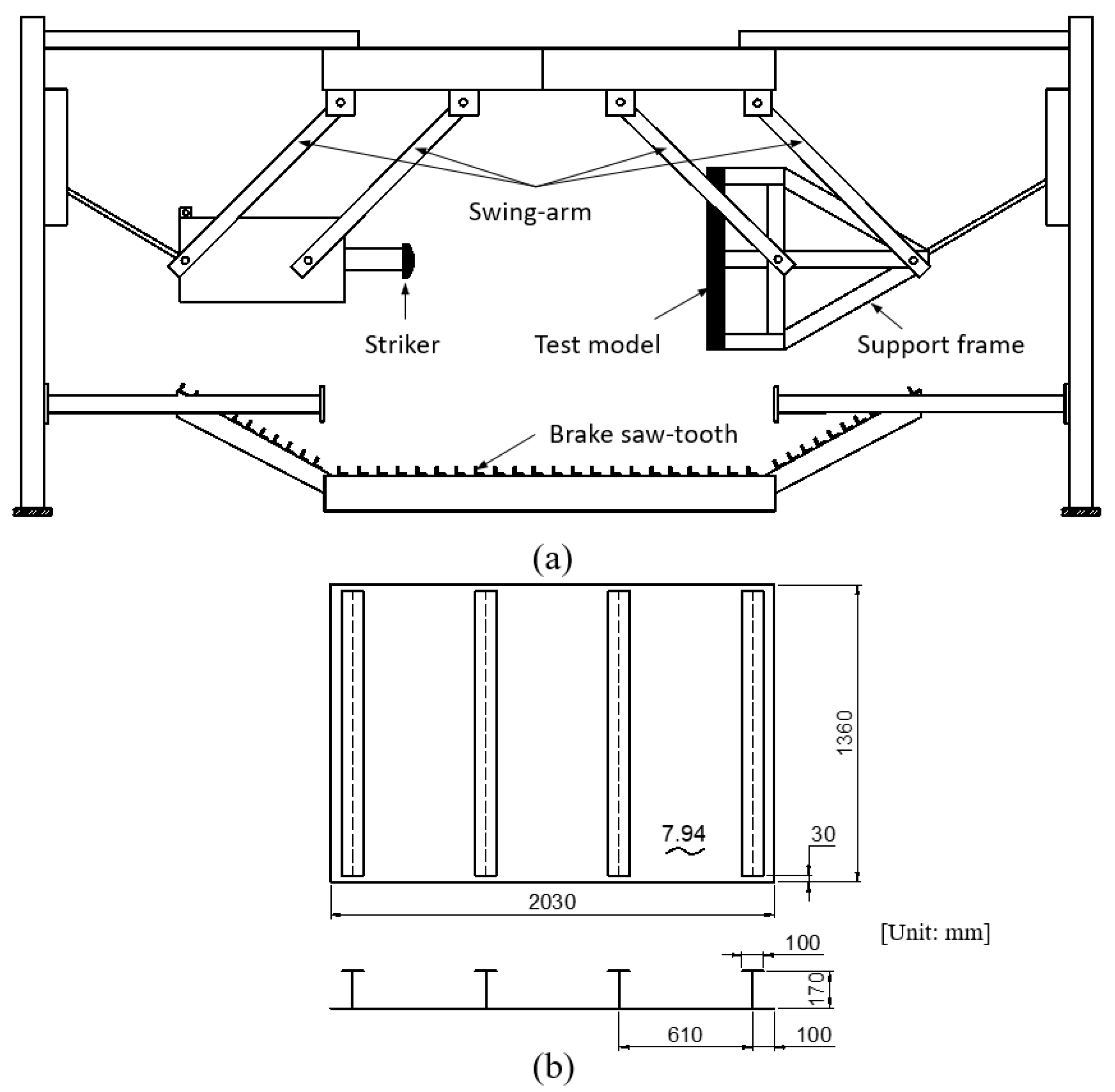
In the experiments [14], four consecutive impact tests were carried out using a large pendulum apparatus, as shown in Figure 5a. The testing machine was designed with a dual pendulum for conveniently producing repeatable mass impacts on a structural component, where one side of the pendulum, connected to a striker, hit the test model mounted on a strong support frame hung on the right of the pendulum. A pillow-block-bearing tool was used to keep the test frame top. The setting allowed each pendulum mass to freely swing with its horizontal orientation relative to the other. The test model was a stiffened plate that was fabricated as the scaled model of midship structures, and its scantling is illustrated in Figure 5b. Mild steel was used for both the plate and stiffeners; the mechanical properties of the plate model materials which were obtained from tensile coupon tests are listed in Table 3. The striker was a rigid spherical indenter made of HS-100 steel. Both the stiffened plate and the striker mounted on the pendulum arms were released simultaneously from a 50° angle and impacted each other horizontally at the bottom of the pendulum arc length. The FARO arm system was used to measure the residual deflection of the tested plate. The impact test conditions and measured deflection results are indicated in Table 4. A detailed description of the experimental setup can be found in Robbins [14].
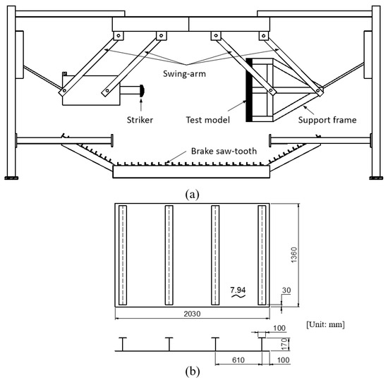
Figure 5.
(a) Schematic of the experimental set-up and (b) geometry of the stiffened plate. The data were from Reference [14].
Table 3.
Mechanical properties of the material of the tested plate model.
Table 4.
Repeated impact test conditions and results.
3.2. Numerical Simulations
The experimental works by Robbins [14] are simulated, in which the boundary conditions are reflected as close as in the tests. The numerical simulations are performed using the Abaqus software 6.13. The FE model consists of the striker and the stiffened plate. The stiffened plate is modeled using shell elements S4R with a mesh size of approximately 15 mm × 15 mm based on the convergence test, while the striker is modeled as a rigid surface. The mechanical properties of the material (Table 3) and the impact test conditions (Table 4) are introduced in the numerical analysis model. The definition of the rest of the numerical model (i.e., the contact algorithm, material, and boundary conditions) is generally similar to what is described in Section 2. Note that the strain rate effect was also considered by using the Cowper–Symonds constitutive equation [32], (see Equation (18)), in which the constants D and q are set as 40.4/s and 5, respectively. The simulation duration time of each impact is set as 0.05 s.
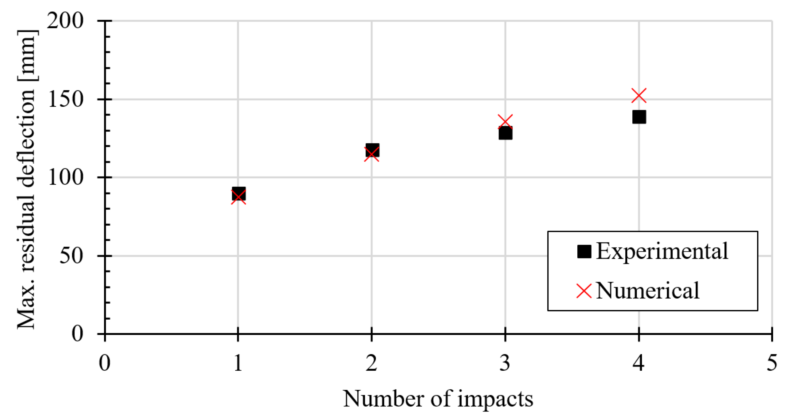
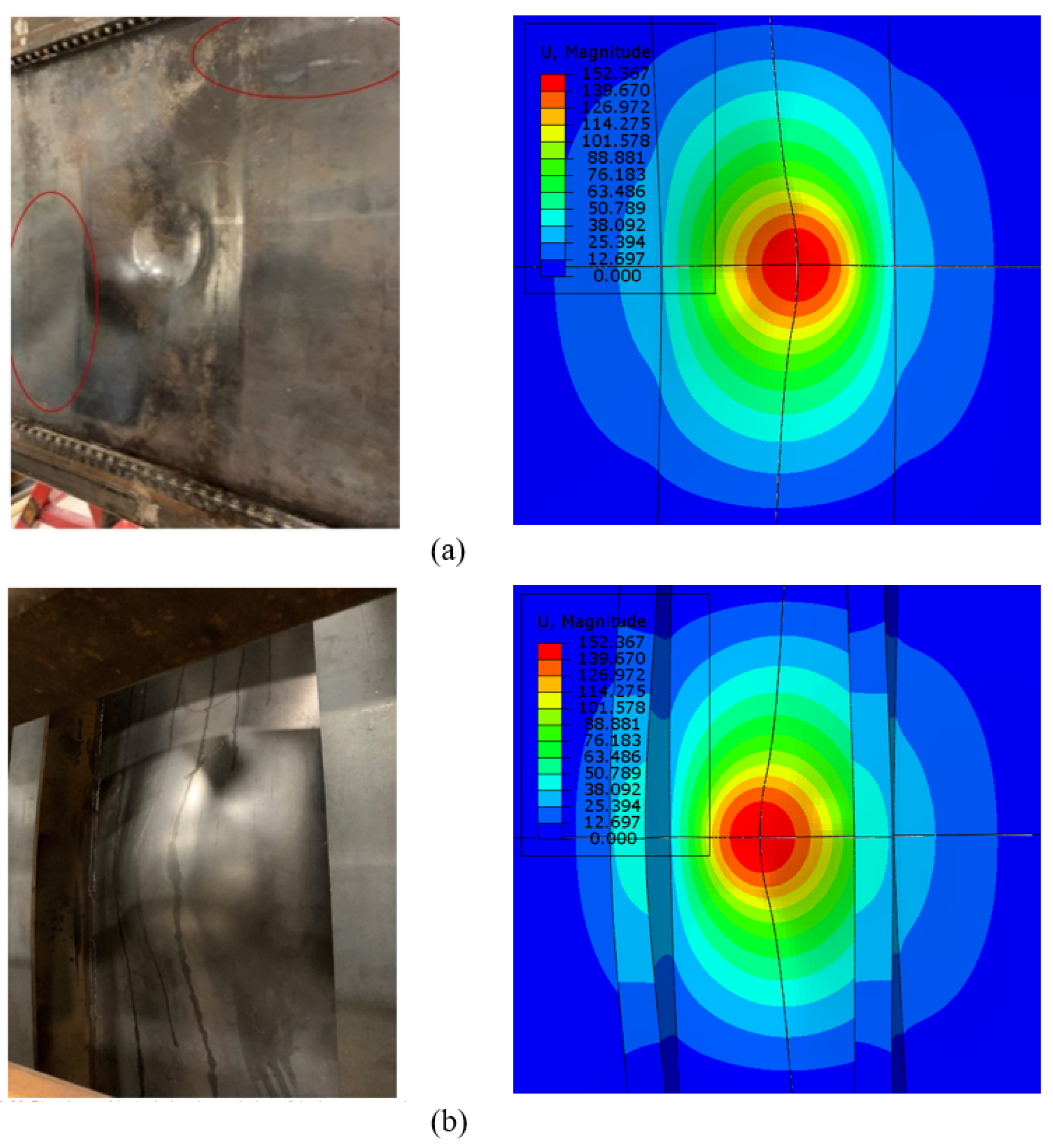
The comparison of the numerical prediction and test results for the maximum residual deflections (i.e., measured at the plate center) is shown in Figure 6, and the results are also given in Table 4. It can be seen that a good correlation between the numerical results and experimental data is obtained. Figure 7 shows the deformed shape of the tested plate model after the 4th impact, in which maximum deflection was visually captured at the plate center, and the stiffeners in both methods experienced a slight deformation. In addition, there was no fracture or tripping in the simulation, which was the same as in the tests, meaning there was considerable agreement between the residual deformation shapes from the test and the simulation. It is concluded that the accuracy of the numerical analysis model is satisfactory. For further validation, by using the same simulation techniques, several experimental works in the previous studies conducted by the author group [3,6,7] were numerically reproduced, and satisfactorily predicted residual deflection evolution of the unstiffened plates [3], grillages [6], and beams [7] under repeated mass impacts was also obtained. Therefore, it can be concluded that the numerical model developed in this study can be used to predict the structural response for marine structures under repeated impact conditions. A discussion on the parametric study results and the derived empirical formulation will be presented in the following sections.

Figure 6.
Comparison of the prediction and test results for the maximum residual deflection of the tested plate throughout four impact events.

Figure 7.
Comparison of the residual deformation shape of the plate model after 4th impact between tests and simulations: (a) plate’s outer side and (b) plate’s inner side (Unit: mm). The red circles denote changes in the curvature of the peripheral surface due to shear buckling behavior.
4. Calculation Results and Discussion
The numerically obtained results for the maximum deflection of the stiffened plates are listed in Table 1, and the impact force and striker velocity time history are discussed. For readability, only typical results will be presented for evaluating the influence of geometry and loading parameters on the structural response; this will be helpful for the development of a practical method for predicting the residual deflections of the repeatedly impacted structures. As discussed in the following subsections, the normalized residual deflection (wr/tp) is plotted with the impact number and with combination parameters to represent the damage evolution of the stiffened plates. Finally, a simple practical formula for predicting the wr/tp of the stiffened plates due to repeated impacts is empirically derived.
4.1. Plastic Strain Distribution and Damage Extent
Figure 8 indicates the typical equivalent plastic strain distribution and deformed shape, for example, of stiffened plates No. 1, No. 2, and No. 3 after the impact load of 15 tons in mass and 3.0 m/s in impact velocity with a striker diameter of 0.8 m throughout five identical impacts. Note that models No. 1 and No. 3 are the same in length, but they differ in width, while the length of model No. 2 is twice (see Table 1); all the analyzing models consist of six stiffeners. It can be seen that the maximum plastic strain occurred at the intersections of the stiffener and middle plate around the impact areas, as well as at the middle plate center for all three models No. 1, No. 2, and No. 3, for the later stage of each impact event. It is apparent that the plastic strain increases, and its distribution spreads out when the impact number increases, regardless of the plate scantlings. In addition, the deformation of the plate after each impact event mainly occurred at the impact location, and it accumulated with the impact number; the stiffener near the impact location is deformed when the impact load is repeated, as noticed in Figure 8.
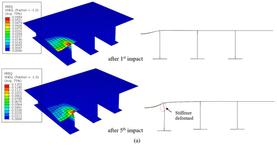
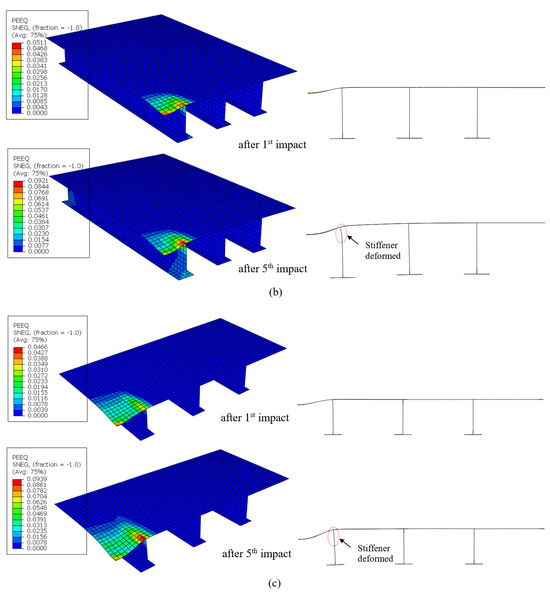
Figure 8.
Equivalent plastic strain distribution (Left) and deformed shape (Right) of quarter stiffened plate models (a) No. 1, (b) No. 2, and (c) No. 3 after 1st impact and 5th impact with the impact condition M15V3 (M15V3 means the striker mass Ms = 15 tons, initial impact velocity V0 = 3.0 m/s).
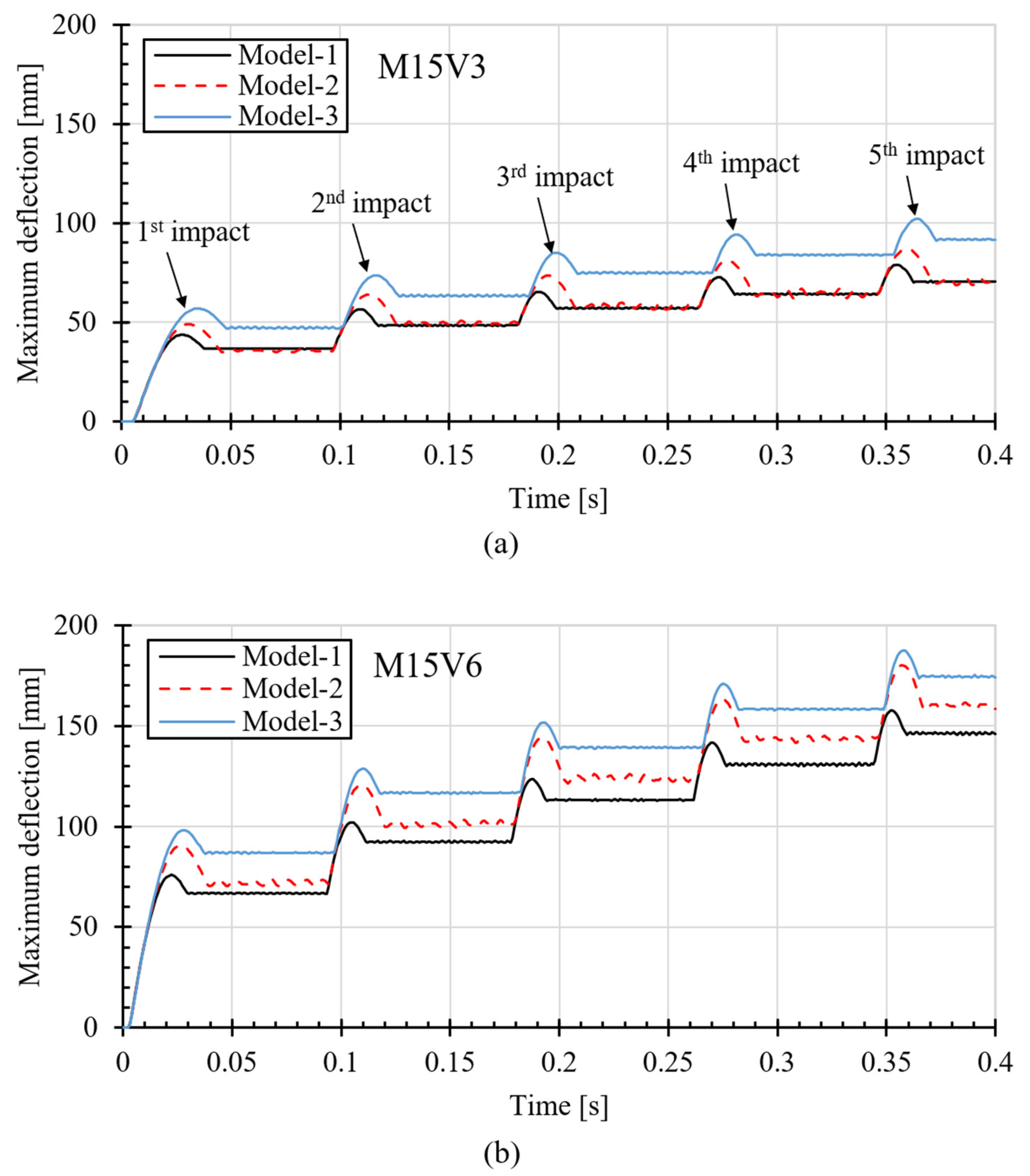
The typical maximum deflection time histories at the plate’s center of models No. 1, No. 2, and No. 3, throughout five impacts with two cases M15V3 and M15V6 (i.e., striker mass of 15 tons and two impact velocity cases of 3.0 m/s and 6.0 m/s), are shown in Figure 9. The structural response feature of the stiffened plates under five impacts is presented, in which during each impact event, the impacted plate experiences a peak response first, and then it rebounds (spring-back) before observing a permanent response, regardless of the model geometry and impact energy. It is seen that the deflection increased with the impact number, while its increment reduced accordingly; it, as expected, also increased with the higher impact energy, while the response time that reached the peak deformations of model No. 1 was shorter than those of models No. 2 and No. 3, having either a longer span (a) or a wider stiffener spacing (b), and this response time decreased when a higher impact velocity was applied throughout all impacts regardless of the scantlings. As also seen in the figures, it is not surprising that the deformation of model No. 3 is greater than that of models No. 1 and No. 2, which has a higher stiffness (a smaller stiffener spacing (No. 1), a longer span (No. 2)), and the vibration after the peak response increased with a reduction in the plate stiffness.

Figure 9.
Time histories of deflection results for models 1–3 with two load cases, (a) M15V3 and (b) M15V6.
4.2. Impact Force and Striker Velocity Time History
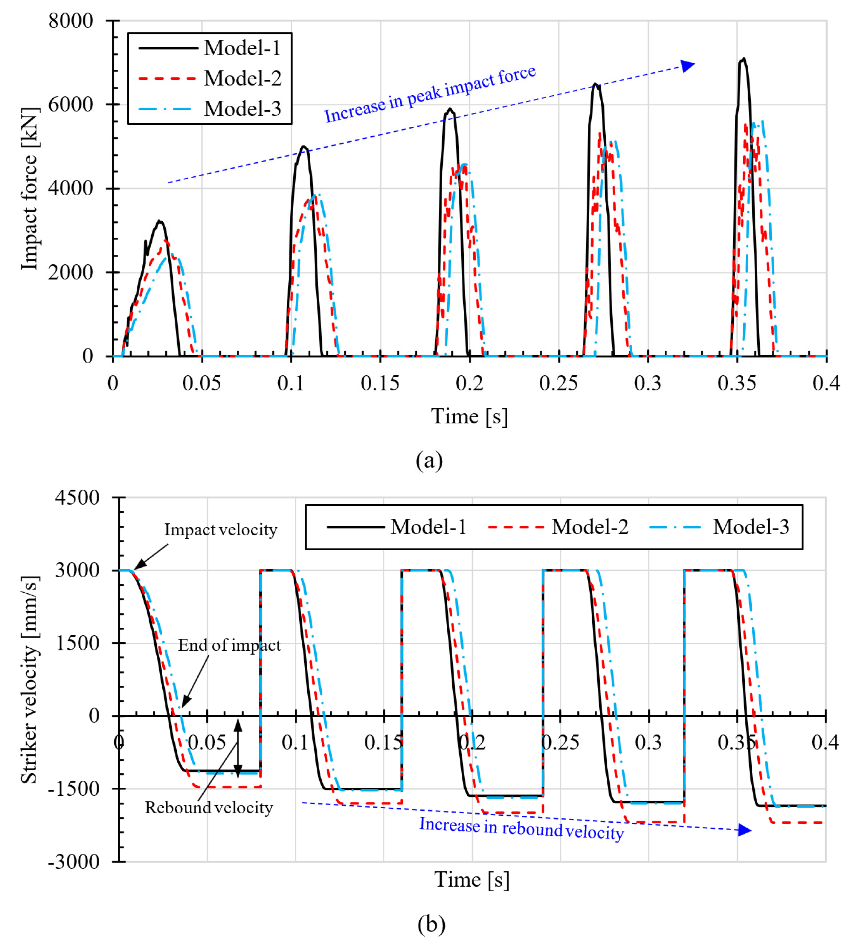
Figure 10 shows the time histories of the impact force and impact velocity during five impacts with an impact case, M15V3, having a striker diameter of 0.8 m. It can be seen that the peak impact force increases while the impact duration decreases with the number of impacts (see Figure 10a), suggesting that the material can recover the elasticity when the impact number rises. This observation is in line with that from the previous research, for example, [5,6,7,16,22]. As a typical time history of the striker velocity, as shown in Figure 10b, for example, for models No. 1, No. 2, and No. 3, there is a slight increase in the rebound velocity when increasing the impact number; this is due to the plate’s elastic energy capacity which increases with the finite deflections [22], indicating the higher rebound velocity found for model No. 2.

Figure 10.
Time histories of (a) impact force and (b) striker velocity with a case of impact load of M15V3.
5. Derivation of Empirical Formulation for Prediction of Residual Deflection Evolution
5.1. General Procedure
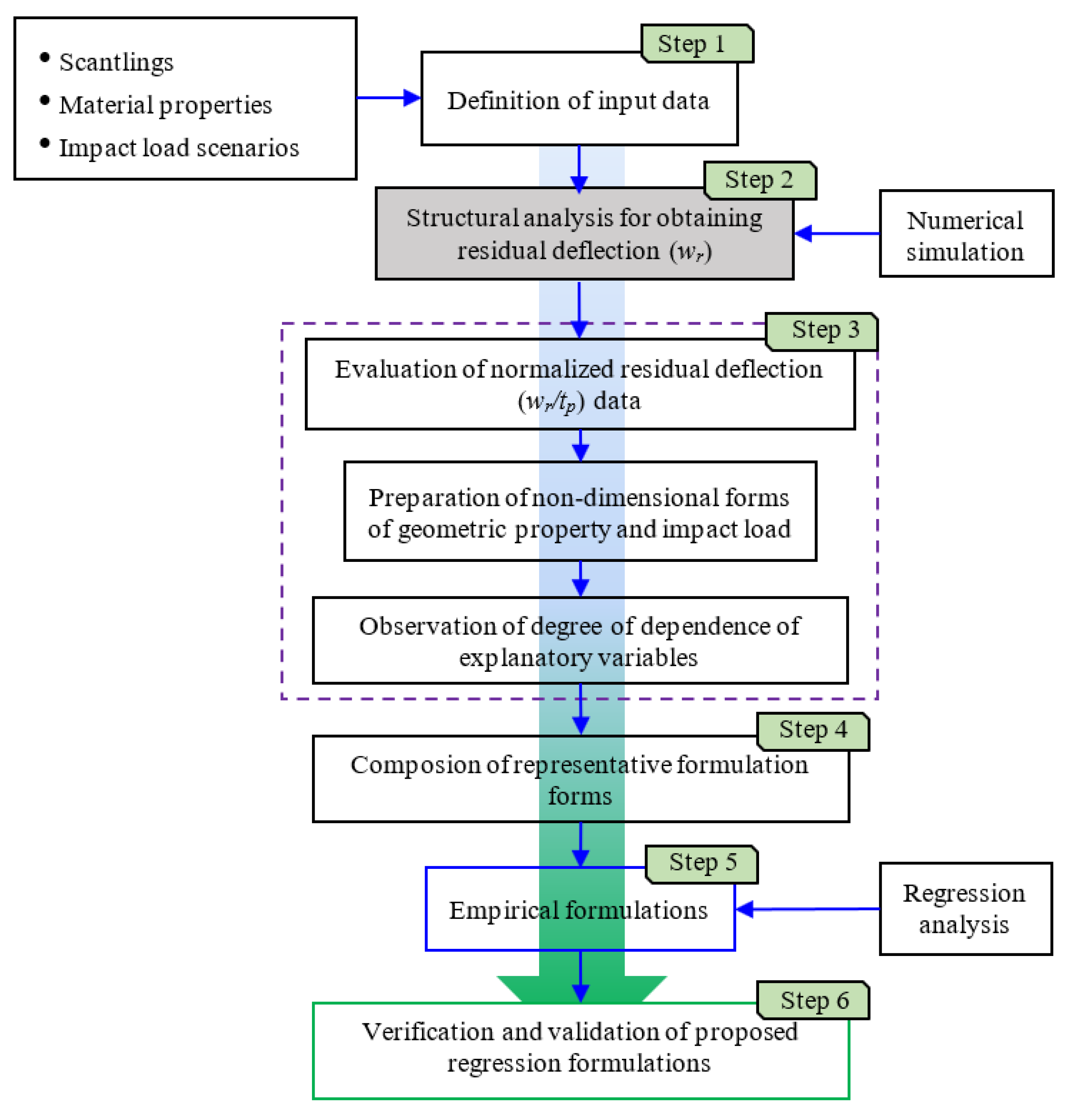
For the design of ice-class vessels, the reliable prediction of the residual deflection evolution of plates subjected to repeated impacts induced by ice collisions is necessary. Several formulae for estimating the damage extents of plates caused by the type of single-impact load have been reported, for example, in Reference [33]. However, as mentioned earlier, while in service, ice-class structures are inherently exposed to repeated impact loads, inferring that the single load may not be a suitable representation of realistic ice impact loads. Several studies [4,6,8,23] developed the analytical method for the prediction of the deflection of structural components due to repeated impacts, but this method seems less accurate because a lot of assumptions for simplicity are inherently made. Truong et al. [25] proposed formulations for the prediction of the residual deflection evolution of steel plates subjected to repeated impact pressures arising from slamming; those formulations could be useful for the design of marine vessels under slamming loads, but might not be suitably applied in solving the same problem for repeated mass impact loadings. Therefore, it is decided to develop formulations for a more reliable prediction of the residual deflection evolution. Here, the parametric study results presented in Section 4 will be used for the derivation of the empirical formulations by regression analysis. The procedure of deriving the formula is summarized in Figure 11; it should be noted that a generally similar procedure of the formulation deviation can be found in Reference [25].
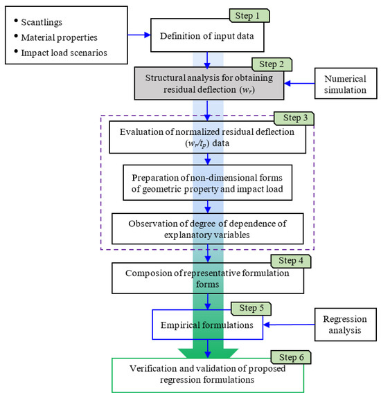
Figure 11.
General procedure for empirical formulation derivation for estimation of residual deflection evolution of plates under repeated impacts.
5.2. Derivation of Empirical Formulation
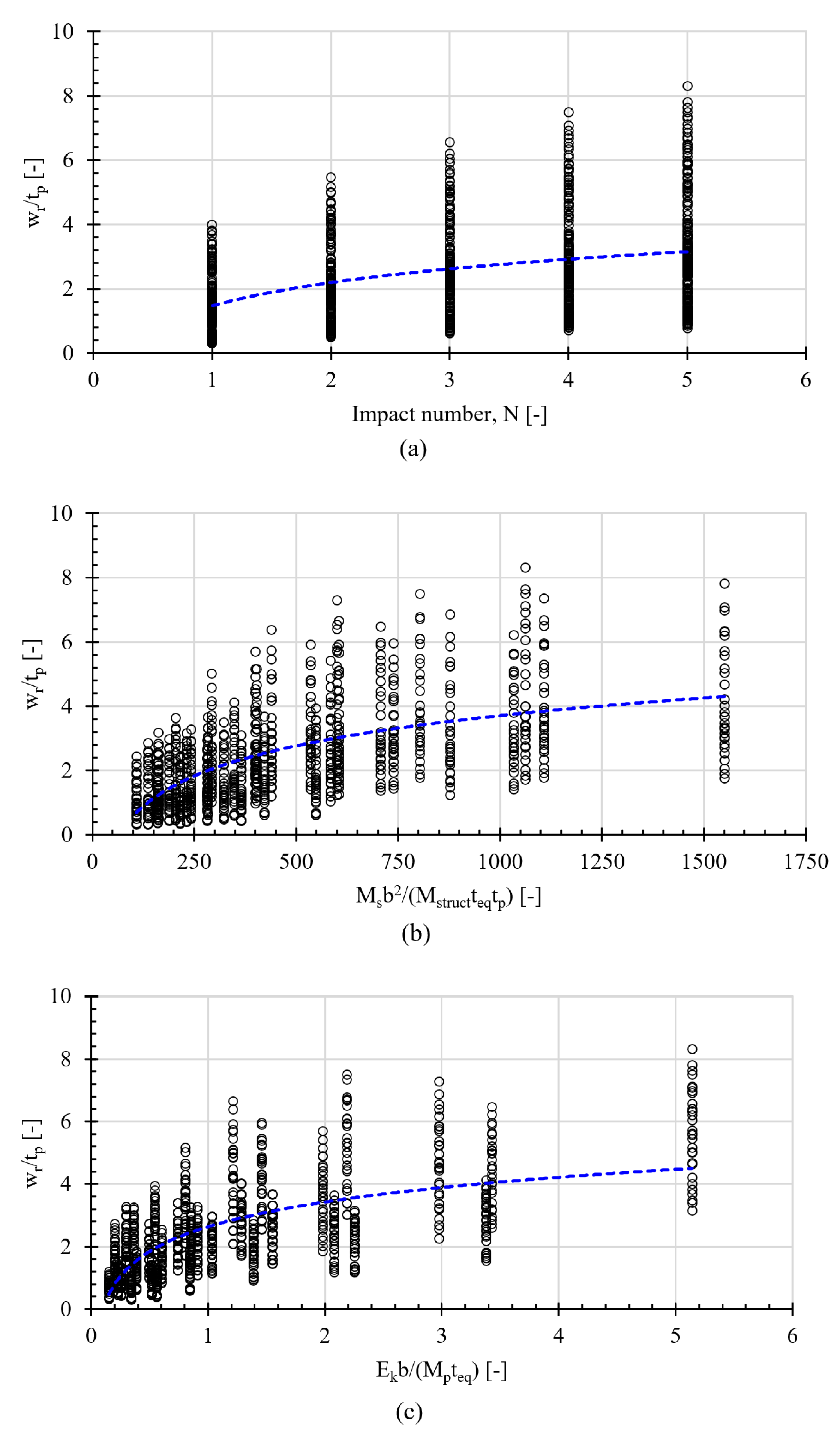
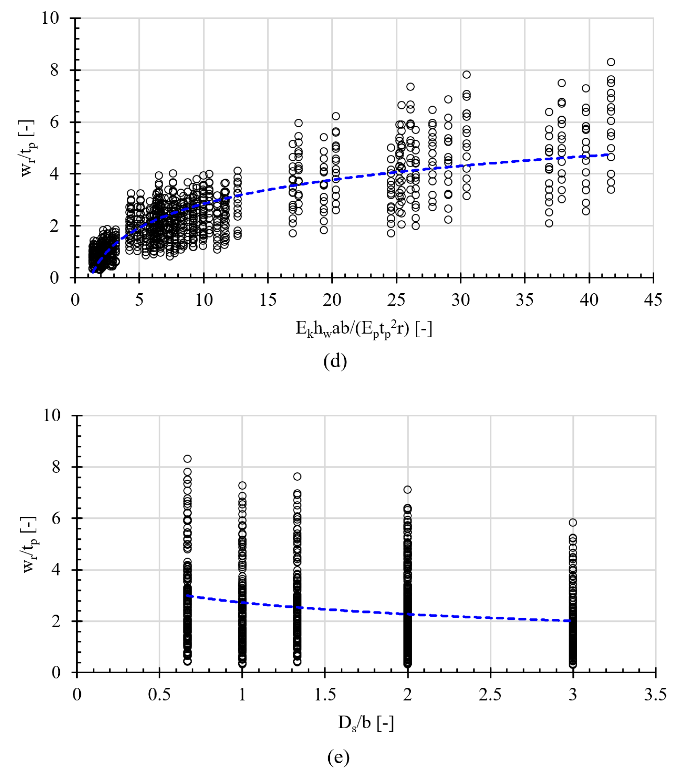
Before deriving the formula, the tendency of the residual deflection with the key non-dimensional parameters is examined based on the results of the parametric study presented in Section 4. Figure 12 shows the tendency of wr/tp with various non-dimensional combination parameters for all of the analysis data. Note that the strongly influenced parameters, including stiffened plate scantlings (i.e., a, b, tp, hw, teq, and r), the mass of the stiffened plate (Mstruct), the striker diameter (Ds), striker mass (Ms), kinetic energy (Ek), and strain energy absorption capacity (Ep) are used to introduce the non-dimensional parameters with combination forms (Rm, Rp, Rs, and Rstr). The relationship between wr/tp and the combining parameter and impact number (N) is defined. This step is taken to analyze the appropriate dependent non-dimensional parameter to derive the formulation. As can be observed from the figure, the residual deflection of the stiffened plates (wr/tp) is monotonically increased or decreased with the non-dimensional combined parameters, except for wr/tp against the number of impacts. When the impact number is increased, the increment of the residual deflection is reduced gradually, i.e., the residual deflection tends to approach certain values; as a result, the equation form for the prediction of the residual deflection against N can be selected as Equation (19) and its modification factors can serve on other parameters. Note that this form has been used in several studies [25,34] for the derivation of formulations for predicting the residual deflection of aluminum alloy and steel plates under a single impulse or repeated impact pressures.
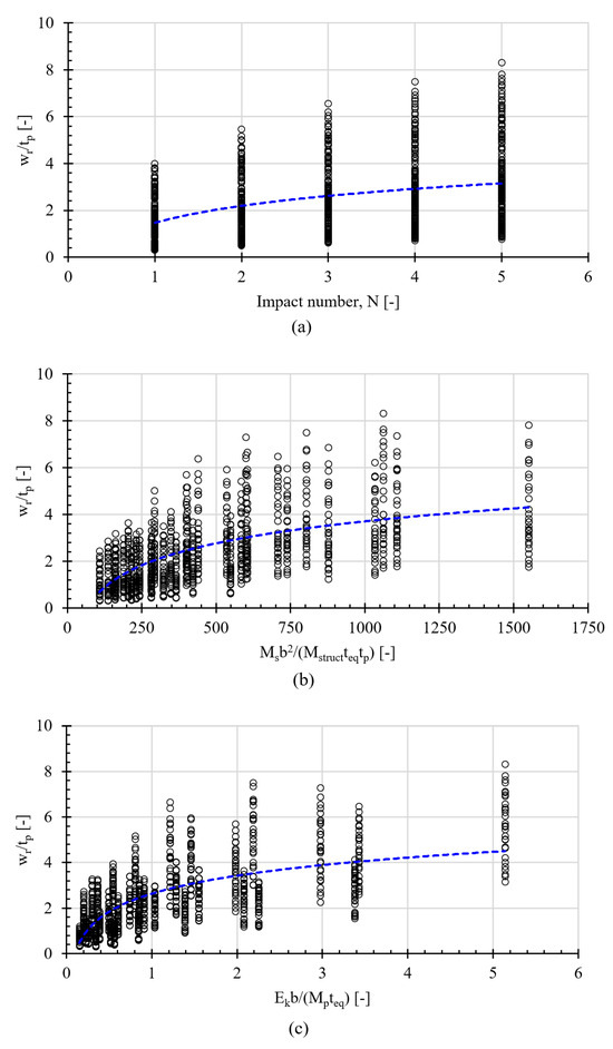
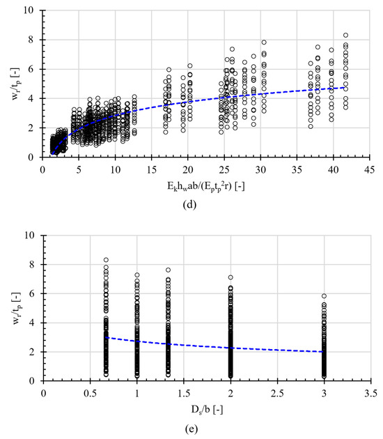
Figure 12.
Tendencies of wr/tp with parameters: (a) N, (b) Rm, (c) Rp, (d) Rs, and (e) Rstr. The blue dotted line denotes the trendline.
Through the nonlinear regression analysis, a set of equations is proposed to predict the residual deflection evolution of stiffened plates under repeated mass impacts, which is expressed as a function of five parameters, including plate scantlings, impact characteristics, and the number of impacts. With the consideration of the strain rate hardening effect in the numerical analysis model, the proposed formula would implicitly comprise the strain rate hardening effect arising from dynamic impacts.
where Rm, Rp, Rs, and Rstr are the design parameters which are determined by the following equations:
where Vstruct is the volume of the stiffened plate and Ns is the number of stiffeners. Note that σT and εT can be calculated by Equations (7) and (8) [31], respectively.
5.3. Verification of Empirical Formulation
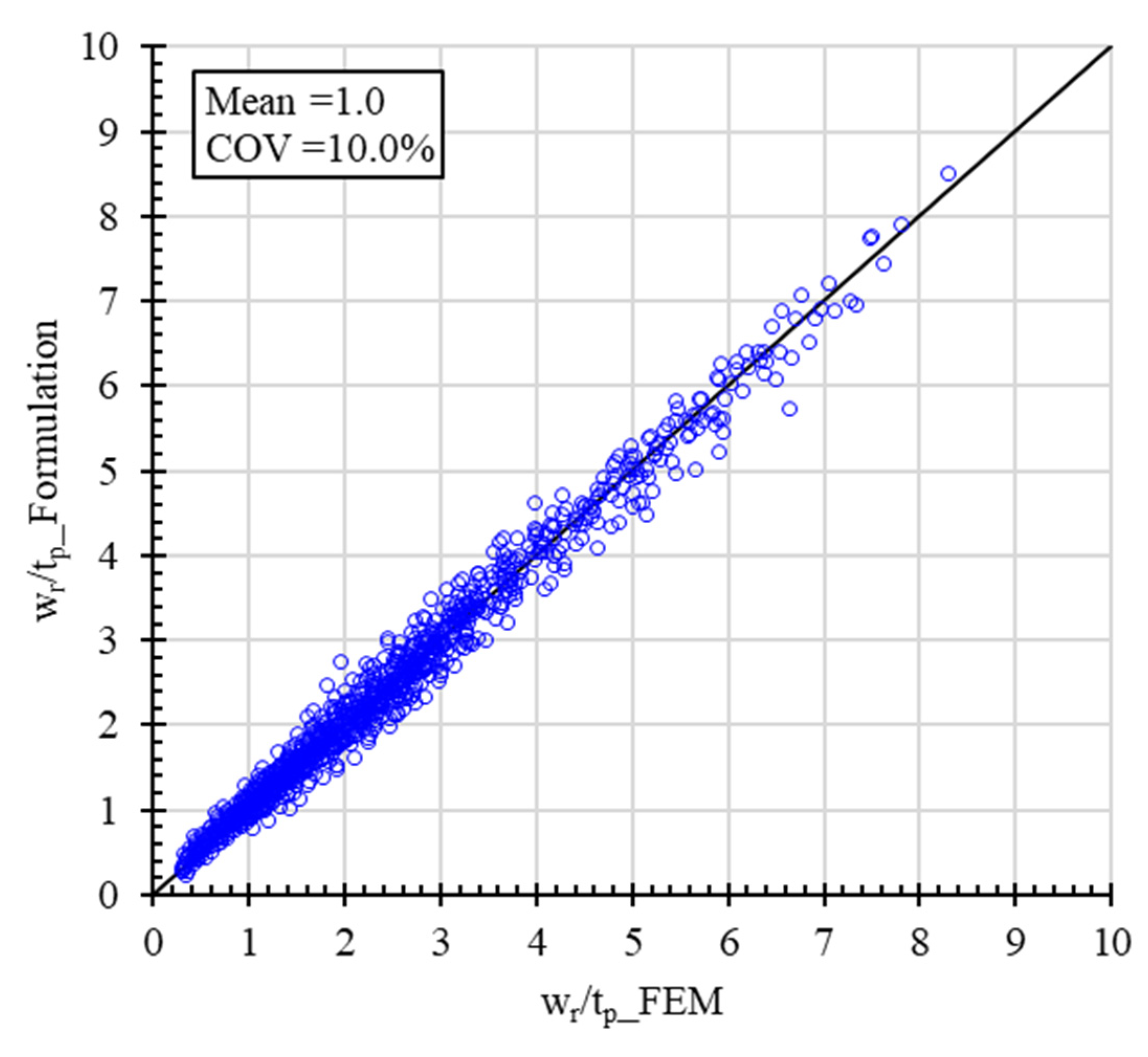
To evaluate the skewness of the predictions, a cross-validation chart is plotted from the derived formulae against numerical results, as illustrated in Figure 13. The diagnostics for the derived formula are further made by plotting Xm (i.e., the ratio of the numerical results to the proposed formulation results) with all of the parameters, as shown in Figure 14. It is evident that no apparent skewness and no trend line of sharpness are found. In addition, the correlation between the residual deflection predicted from the proposed formula and the numerical method is close to unity together with a COV (coefficient of variation) of 10.0%. This observation indicates that the proposed formula can be used as an alternative practical way for numerical simulations. With the proposed one, the residual deflection evolution of stiffened plates with actual scantlings subjected to repeated mass impacts can be conveniently and quickly predicted without any extreme efforts in simulations, as mentioned earlier.

Figure 13.
Comparison of the predicted residual deflection of stiffened plates using the proposed formula and the numerically obtained data.


Figure 14.
Plotting of Xm against non-dimensional parameters: (a) N, (b) Rm, (c) Rp, (d) Rs, and (e) Rstr for the residual deflection evolution of stiffened plates. The black circle and red dotted line denote Xm and the skewness trendline, respectively.
5.4. Accuracy of Proposed Formulation
To verify the accuracy of the proposed formula, comparisons of existing methods and numerical simulations with the proposed formula in predicting residual deflection are conducted.
5.4.1. Comparison with Existing Formulations
A comparison of the results obtained from the derived formula with those from published formulations related to the repeated mass impact-induced residual deflection of actual marine structures would be preferable. Nevertheless, it seems that no related formulations for the prediction of the residual deflections of stiffened plates are available. The simplified analytical method proposed by Jones [4], even for unstiffened plates (with supported and fully clamped conditions), is herein referred to as an early validation. Note that Jones’s equations [4], Equations (30)–(33), were based on an assumption of rigid, perfectly plastic material for unstiffened plates, and the strain rate hardening effect was not taken into account for those existing formulations. Figure 15 shows the comparison of the results calculated from Jones’s equations and those from the proposed empirical formula.
where N is the impact number, m is the boundary condition (i.e., m = 0, and m = 1 are for the simply supported condition and the fully clamped condition, respectively), Ω is the non-dimensional initial kinetic energy, γ is the mass ratio, and βJ is the aspect ratio (0 < βJ ≤ 1); these variables are defined as in Equations (30)–(33) [4].

Figure 15.
Comparison of the residual deflection predicted by the newly proposed formula with existing formulation and FEM [4].
As shown in Figure 15, although the material behavior used in both methods is different (i.e., Jones [4] adopted a rigid, perfectly plastic material without strain rate hardening effect, while the current formulation implicitly considers both the strain hardening and strain rate effect which were already considered in FEM), Jones’s formulations with the simply supported condition show a somewhat accurate prediction of the residual deflection of stiffened plates, especially for the lower deflection range. Nevertheless, a large uncertainty (i.e., high COV) is observed, and a significant variation in the tendency of deflection evolution when it becomes more serious (high-impact energy cases) is also noticed. In the case of using the fully clamped condition, a less accurate solution is detected, indicating the large mean and COV values. It should be noted that these existing formulations were derived only for unstiffened plates, and the ideal boundary conditions (fully clamped or simply supported) are quite different from those of the stiffened plate where the interaction of stiffeners with plates is provided. Recall that Jones’s formulations were derived using a rigid, perfectly plastic material, neglecting the strain rate effect. The omission of the strain hardening and strain rate effect probably caused a large variation in the estimated plastic response of the marine steel structures subjected to high dynamic loadings (i.e., impacts or impulse). This suggests that Jones’s formulations were not sufficiently validated in predicting the residual deflection evolution of steel structures due to repeated impacts, since the important feature of the steel material was not fully reflected. Furthermore, unlike the formulations proposed in this study, Jones’s formulations could not consider a wide range of strikers, which may vary in size in reality. It is revealed that conducting experimental tests on actual scantling models with realistic impact scenarios is extremely arduous; hence, the numerical simulation method is often promisingly preferable for the further validation of the derived formulations.
5.4.2. Comparison with Numerical Simulations
Since experimental residual deflection data for actual stiffened plates subjected to repeated mass impacts are still limited, specific configurations that have scantlings of actual polar class vessels, listed in Table 5, are used to further verify the proposed formula through the numerical simulations using the Abaqus software. A total of three stiffened plates (see Table 5) were analyzed. Two 0.8 m-diameter striker masses of 12 tons and 20 tons and two initial impact velocities of 5.0 m/s and 7.0 m/s are considered. Five identical impacts for each stiffened plate are performed. The numerical modeling technique described in Section 2, involving the type and size of elements, material properties, boundary conditions, and computation time, is generally applied to the current validation simulations.
Table 5.
Scantling of stiffened plates and load conditions for verification of the proposed formula.
The residual deflection results obtained from the numerical analyses and the proposed formula for all cases are shown in Figure 16. As seen from the figure, the value of Xm is close to unity together with a COV of 3.6% for all residual deflections, while larger uncertainty is found when the existing formulations are used. Therefore, it can be inferred that the proposed formula delivered good accuracy and its reliability is confirmed.
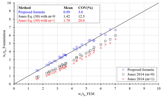
Figure 16.
Verification of predicted maximum residual deflections using the proposed formula with numerically obtained data [4].
6. Conclusions
In this study, a practical formula was developed to predict the residual deflection evolution of stiffened steel plates in marine vessels against repeated mass impacts. The numerical analysis model was first developed and substantiated against published relevant test data. A parametric study was performed for various stiffened plates with actual scantlings with different impact load scenarios, and subsequently, the numerically obtained residual deflection results were utilized to propose the empirical formula. The proposed formula was validated through comparison with existing formulations and numerical simulations. Based on the results of the study, the following conclusions can be drawn:
- The numerical simulation results showed that the deformation after each impact mainly occurred at the impact location, and the stiffeners near the impact location progressively deformed when the impact number rose. The residual deflection of the stiffened steel plates due to the first impact was the most significant and after consecutive impacts, the deflection tended to approach a certain value regardless of the plate scantlings, impact energy, or stiffener shapes. The peak impact force and the rebound velocity of the striker increased, whereas the impact duration reduced with the number of impacts.
- The accuracy and reliability of the newly proposed formula were verified using relevant existing formulations and numerical simulations. The proposed formula is expected to reliably estimate the residual deflection of steel-stiffened plates due to repeated impacts induced by contact with floating objects or ice floes. The formula can be conveniently used in the early marine structure design stage without the need for any numerical simulations or analytical works.
- Furthermore, the proposed numerical simulation techniques, validated with existing test data, are capable of estimating the deflection accumulation of stiffened plates under repeated mass impacts with reasonable accuracy and reliability. Hence, the techniques may be confidently applied for further research on relevant structures in damage-collision assessments.
Comparisons with the existing formulae demonstrate that the proposed method is better, but it might be valid only for the range of the scantlings and loadings considered in this study. Further studies seem to be required to widen the range of validity of the proposed formula, especially for the effects of impact loads involving shapes and rigidity of the striking body, as well as different boundary conditions (i.e., more complicated structure scantlings containing adjacent structural components), benefitting a more reliable assessment method for the marine structural design.
Author Contributions
Conceptualization, V.-V.H., S.-R.C. and D.D.T.; methodology, V.-V.H. and D.D.T.; software, D.D.T.; validation, V.-V.H., X.-P.D. and D.D.T.; formal analysis, V.-V.H., S.-R.C. and D.D.T.; investigation, X.-P.D.; resources, D.D.T.; data curation, V.-V.H. and D.D.T.; writing—original draft preparation, V.-V.H. and D.D.T.; writing—review and editing, S.-R.C. and D.D.T.; visualization, X.-P.D.; supervision, D.D.T.; project administration, V.-V.H. and D.D.T.; funding acquisition, D.D.T. All authors have read and agreed to the published version of the manuscript.
Funding
This research was funded by the Nha Trang University, Vietnam (Grant No. TR2023-13-04).
Institutional Review Board Statement
Not applicable.
Informed Consent Statement
Not applicable.
Data Availability Statement
The original contributions presented in this study are included in the article. Further inquiries can be directed to the corresponding author.
Conflicts of Interest
Author Sang-Rai Cho was employed by the company UlsanLab Inc. The remaining authors declare that the research was conducted in the absence of any commercial or financial relationships that could be construed as a potential conflict of interest.
References
- Zhu, L.; Faulkner, D. Damage estimate for plating of ships and platforms under repeated impacts. Mar. Struct. 1996, 9, 697–720. [Google Scholar] [CrossRef]
- Huang, Z.; Chen, Q.; Zhang, W. Pseudo-shakedown in the collision mechanics of ships. Int. J. Impact Eng. 2000, 24, 19–31. [Google Scholar] [CrossRef]
- Chae, G.I. Nonlinear Structural Behavior Due to Repeated Interaction between Ice Breaking Commercial Ships and Sea Ice. Master’s Thesis, University of Ulsan, Ulsan, Republic of Korea, 2008. [Google Scholar]
- Jones, N. Pseudo-shakedown phenomenon for the mass impact loading of plating. Int. J. Impact Eng. 2014, 65, 33–39. [Google Scholar] [CrossRef]
- Cho, S.-R.; Truong, D.D.; Shin, H.K. Repeated lateral impacts on steel beams at room and sub-zero temperatures. Int. J. Impact Eng. 2014, 72, 75–84. [Google Scholar] [CrossRef]
- Truong, D.D.; Shin, H.K.; Cho, S.-R. Repeated lateral impacts on steel grillage structures at room and sub-zero temperatures. Int. J. Impact Eng. 2018, 113, 40–53. [Google Scholar] [CrossRef]
- Truong, D.D.; Jung, H.-J.; Shin, H.K.; Cho, S.-R. Response of low-temperature steel beams subjected to single and repeated lateral impacts. Int. J. Nav. Arch. Ocean Eng. 2018, 10, 670–682. [Google Scholar] [CrossRef]
- Zhu, L.; Shi, S.; Jones, N. Dynamic response of stiffened plates under repeated impacts. Int. J. Impact Eng. 2018, 117, 113–122. [Google Scholar] [CrossRef]
- Zhu, L.; Guo, K.L.; Li, Y.G.; Yu, T.X.; Zhou, Q.W. Experimental study on the dynamic behavior of aluminum foam sandwich plates under single and repeated impacts at low temperature. Int. J. Impact Eng. 2018, 114, 123–132. [Google Scholar] [CrossRef]
- Guo, K.L.; Zhu, L.; Li, Y.G.; Yu, T.X.; Shenoi, A.; Zhou, Q.W. Experimental investigation on the dynamic behavior of aluminum foam sandwich plate under repeated impacts. Compos. Struct. 2018, 200, 298–305. [Google Scholar] [CrossRef]
- Guo, K.; Zhu, L.; Li, Y.; Yu, T. Numerical study on mechanical behavior of foam core sandwich plates under repeated impact loadings. Compos. Struct. 2019, 224, 111030. [Google Scholar] [CrossRef]
- Duan, F.; Liu, J.; Wang, G.; Yu, Z.L. Dynamic behavior of aluminum alloy plates with surface cracks subjected to repeated impacts. Ships Offshore Struct. 2019, 14, 478–491. [Google Scholar] [CrossRef]
- Zeng, Y.; Chen, H.; Yu, R.; Shen, Z.; Yu, Z.; Liu, J. Experimental research on dynamic behavior of circular mild steel plates with surface cracks subjected to repeated impacts in low temperature. Shock Vib. 2020, 2020, 3713709. [Google Scholar] [CrossRef]
- Robbins, M.L. Characterization of Post-Yield Behavior of a Warship Grillage Subject to Repeated Impacts. Master’s Thesis, Memorial University of Newfoundland, St. John’s, NL, Canada, 2020. [Google Scholar]
- Zhang, Y.; Li, Y.; Guo, K.; Zhu, L. Dynamic mechanical behaviour and energy absorption of aluminium honeycomb sandwich panels under repeated impact loads. Ocean Eng. 2021, 219, 108344. [Google Scholar] [CrossRef]
- He, X.; Guedes Soares, C. Experimental study on the dynamic behaviour of beams under repeated impacts. Int. J. Impact Eng. 2021, 147, 103724. [Google Scholar] [CrossRef]
- He, X.; Soares, C.G. Numerical study on the pseudo-shakedown of beams under repeated impacts. Ocean Eng. 2021, 242, 110137. [Google Scholar] [CrossRef]
- He, X.; Soares, C.G. Pseudo-shakedown of rectangular plates under repeated impacts. Mar. Struct. 2022, 85, 103258. [Google Scholar] [CrossRef]
- Cai, W.; Zhu, L.; Qian, X. Dynamic responses of steel plates under repeated ice impacts. Int. J. Impact Eng. 2021, 162, 104129. [Google Scholar] [CrossRef]
- He, X.; Garbatov, Y.; Soares, C.G. Analysis of pseudo-shakedown of rectangular plates under repeated impacts. Ocean Eng. 2022, 265, 112609. [Google Scholar] [CrossRef]
- Zhu, L.; Wang, X.; Guo, K.; Cai, W.; Jones, N.; Dai, S. Effects of indenter geometry on pseudo-shakedown of steel plates under repeated mass impacts. Int. J. Impact Eng. 2023, 185, 104865. [Google Scholar] [CrossRef]
- He, X.; Soares, C.G. Experimental and numerical study on the dynamic response of rectangular plates under repeated impacts. Mar. Struct. 2024, 96, 103606. [Google Scholar] [CrossRef]
- Xu, J.; Guo, Y.; He, Z.; Li, Z.; Liu, G.; He, Y. Simplified analytical method for predicting the large deformation of stiffened plates with initial cracks under repeated impacts. Ocean Eng. 2024, 304, 117886. [Google Scholar] [CrossRef]
- Jones, N. Slamming damage. J. Ship Res. 1973, 17, 80–86. [Google Scholar] [CrossRef]
- Truong, D.D.; Huynh, V.V.; Jang, B.-S.; Quach, H.N.; Dang, X.-P.; Duong, H.D.; Cho, S.-R. Empirical formulations for prediction of permanent set evolution of steel plates due to repeated impulsive pressure loadings induced by slamming. Ocean Eng. 2023, 268, 113430. [Google Scholar] [CrossRef]
- Daley, C.; Kim, H.W. Ice collision forces considering structural deformation. In Proceedings of the ASME 2010 29th International Conference on Ocean, Offshore and Arctic Engineering (OMAE2010), Shanghai, China, 6–11 June 2010. [Google Scholar]
- Zhang, M.; Liu, J.X. Experimental and numerical analysis of tanker double-hull structures punched by a wedge indenter. In Proceedings of the 6th International Conference on Marine Structures (MARSTRUCT 2017), Lisbon, Portugal, 8–10 May 2017. [Google Scholar]
- Villavicencio, R.; Soares, C.G. Numerical modelling of the boundary conditions on beams stuck transversely by a mass. Int. J. Impact Eng. 2011, 38, 384–396. [Google Scholar] [CrossRef]
- Villavicencio, R.; Liu, B.; Soares, C.G. Experimental and numerical analysis of a tanker side panel laterally punched by a knife edge indenter. Mar. Struct. 2014, 37, 173–202. [Google Scholar] [CrossRef]
- Storheim, M.; Amdahl, J. On the sensitivity to work hardening and strain-rate effects in nonlinear FEM analysis of ship collisions. Ships Offshore Struct. 2015, 12, 100–115. [Google Scholar] [CrossRef]
- Cho, S.-R.; Choi, S.I.; Son, S.K. Dynamic material properties of marine steels under impact loadings. In Proceedings of the 2015 World Congress on Advances in Structural Engineering and Mechanics, ASEM15, Incheon, Republic of Korea, 25–29 August 2015. [Google Scholar]
- Cowper, G.; Symonds, P. Strain Hardening and Strain Rate Effects in the Loading of Cantilever Beams; Report No. 28 1957; Brown University: Providence, RI, USA.
- Liu, B.; Villavicencio, R.; Guedes Soares, C. Simplified analytical method to evaluate tanker side panels during minor collision incidents. Int. J. Impact Eng. 2015, 78, 20–33. [Google Scholar] [CrossRef]
- Cerik, B.C. Large inelastic deformation of aluminium alloy plates in high-speed vessels subjected to slamming. J. Mar. Sci. Technol. 2017, 22, 301–312. [Google Scholar] [CrossRef]


Disclaimer/Publisher’s Note: The statements, opinions and data contained in all publications are solely those of the individual author(s) and contributor(s) and not of MDPI and/or the editor(s). MDPI and/or the editor(s) disclaim responsibility for any injury to people or property resulting from any ideas, methods, instructions or products referred to in the content. |
© 2024 by the authors. Licensee MDPI, Basel, Switzerland. This article is an open access article distributed under the terms and conditions of the Creative Commons Attribution (CC BY) license (https://creativecommons.org/licenses/by/4.0/).