Article

Conceptual Design and Structural Performance Analysis of an Innovative Deep-Sea Aquaculture Platform

1
School of Naval Architecture and Ocean Engineering, Dalian University of Technology, Dalian 116024, China
2
PowerChina Huadong Engineering Corporation Limited, Hangzhou 311122, China
*
Authors to whom correspondence should be addressed.
J. Mar. Sci. Eng. 2024, 12(7), 1058; https://doi.org/10.3390/jmse12071058
Submission received: 11 May 2024 / Revised: 12 June 2024 / Accepted: 20 June 2024 / Published: 24 June 2024
(This article belongs to the Section Ocean Engineering)

Abstract

:
This paper proposes a conceptual design of an innovative deep-sea aquaculture platform that integrates a steel structural framework and high-density polyethylene (HDPE) floats. It aims to overcome the limitations of prevailing aquaculture equipment, including inadequate resistance to strong wind and waves, complex technologies, and prohibitively high costs. The design scheme and key parameters of the main platform, the netting system, and the mooring systems are presented. Based on the stochastic design wave method, the characteristic load response scenarios and design wave parameters are determined and analyzed. Strength analysis is conducted to assess the structural performance, vulnerabilities, and overall safety of the platform under various characteristic load conditions. The results indicate that the Von Mises stress levels across different sections of the platform conform to the allowable stress thresholds under various characteristic load conditions. However, the stress levels of the platform are notably higher when subjected to characteristic loads associated with vertical shear, vertical bending moments, and torsion about the horizontal axis, which requires further efforts in the design process to enhance the structural safety of the platform. The proposed design methodology and the presented research results can provide a wide range of references for the design and analysis of deep-sea fisheries aquaculture equipment.

1. Introduction

Being confronted with the demanding challenges of increasing pollution and constrained environmental carrying capacities in nearshore seas, marine aquaculture in deeper sea regions has attracted extensive attention worldwide [1,2]. This strategic relocation effectively addresses issues related to nearshore environmental degradation, limited capacity, and recurrent disease outbreaks. Meanwhile, it helps augment the space available for aquaculture, thus improving both operational efficiency and production yield. However, conventional high-density polyethylene (HDPE) aquaculture cages demonstrate inadequate resistance to wind and wave forces in demanding marine environments. Although large steel cages provide enhanced durability under such conditions, their costs and the complexity concerning the design and construction inevitably increase aquaculture expenses. Therefore, it is of great significance to develop high-performance, cost-effective, and environmentally sustainable equipment for deep-sea aquaculture.
The structural performance of aquaculture equipment represents a critical aspect of its design and optimization. The finite element method (FEM) and physical experiments are typically used for structural strength analyses of such equipment [3,4,5,6]. Such analyses help identify potential failure modes and optimize the equipment’s structural configuration. Aquaculture equipment generally comprises three main components: the main structures, the netting systems, and the mooring systems. The main structure, which sustains the primary load from wave forces, is crucial for ensuring the safety of the cage structure. Current research on the structural performance of aquaculture equipment primarily concentrates on the main structures, with a particular focus on the use of HDPE materials for float frames. In contrast, studies on large steel structural cage frameworks are limited.
Lee et al. [7] employed a mass-spring model to simulate various components of aquaculture cages. In their study, mathematical modeling was utilized to analyze the vibrations and deformations under the influence of waves and currents. Zhao et al. [8] developed failure criteria for local stresses on cage floats through FEM geometrical model tests. Huang et al. [9,10,11,12] applied the FEM and conducted associated experiments to investigate the deformation, yield strength, failure phenomena, and fatigue strength of circular and hexagonal cage floats. Li et al. [13,14,15] examined the dynamic responses of aquaculture cage float systems to sea currents and waves based on three-dimensional hydroelasticity theory. Xu et al. [16] constructed a finite element model of the cage with ANSYS to analyze stresses and deformations under wave action. The model and the numerical analysis were validated through a series of physical model tests. Zhang et al. [17] explored the structural performance of aquaculture cages in wave environments via theoretical analysis, hydroelastic modeling, and wave numerical simulations, which identified the floats as particularly vulnerable components.
In addition to HDPE aquaculture cages, several scholars have proposed diverse conceptual aquaculture equipment and investigated its structural performance. Sun et al. [18] proposed a truss-type offshore cage and calculated the load responses of the cage float structure using the Morison equation. Meanwhile, the FEM was employed to verify the yield strength of the float structure. Zitti et al. [19,20] introduced a cylindrical cage with a central column and investigated its dynamic behavior under various environmental loads. Ma [21] designed a platform-type aquaculture cage and carried out hydrodynamic calculations, structural strength analysis, and fatigue life assessments. Zhang [22] developed a truss cage analysis model based on the Morison formula and rigid body kinematics theory. The structural strength of the cage under wave loads was analyzed. Pang et al. [23] used ANSYS to create a finite element analysis model of a jack-up offshore net cage. The structural performance analyses were then conducted to determine the structural deformations and stress distributions of various components under operational and self-storage conditions.
This study proposes an innovative design for a deep-sea aquaculture platform. The motivation is to address the limitations of existing cages concerning inadequate resistance to wind and waves, technical complexities, and high costs. The presented design integrates a steel structural frame with HDPE floats based on an extensive review of current research advances and trends in deep-sea equipment technology [24,25,26,27]. In comparison with conventional HDPE circular cages, the proposed design demonstrates enhanced wave resistance with less consumption of steel, which contributes to a reduction in initial investment costs relative to large-scale steel structures. The floats employed in the presented design are highly corrosion-resistant and modular. It facilitates straightforward assembly, disassembly, and replacement of individual units to ensure operational safety throughout their service life. The aquaculture platform must possess adequate structural strength to withstand various wave load conditions and enhance its safety. Hence, it is essential to identify and evaluate the most critical wave load conditions and draw on the structural characteristics of the platform.
The structure of this paper is organized as follows: Section 2 proposes the concept of an innovative deep-sea aquaculture platform. Section 3 elaborates on the adopted methodology and principles, including the interactive conceptual design method, the principal dimension design method, and the structural strength analysis and verification method of the platform. Section 4 describes the design scheme and numerical model of the aquaculture platform. In Section 5, the optimization results of the main dimensional parameters are presented, and the structure is analyzed and calibrated under various characteristic load conditions. Finally, Section 6 concludes the study.

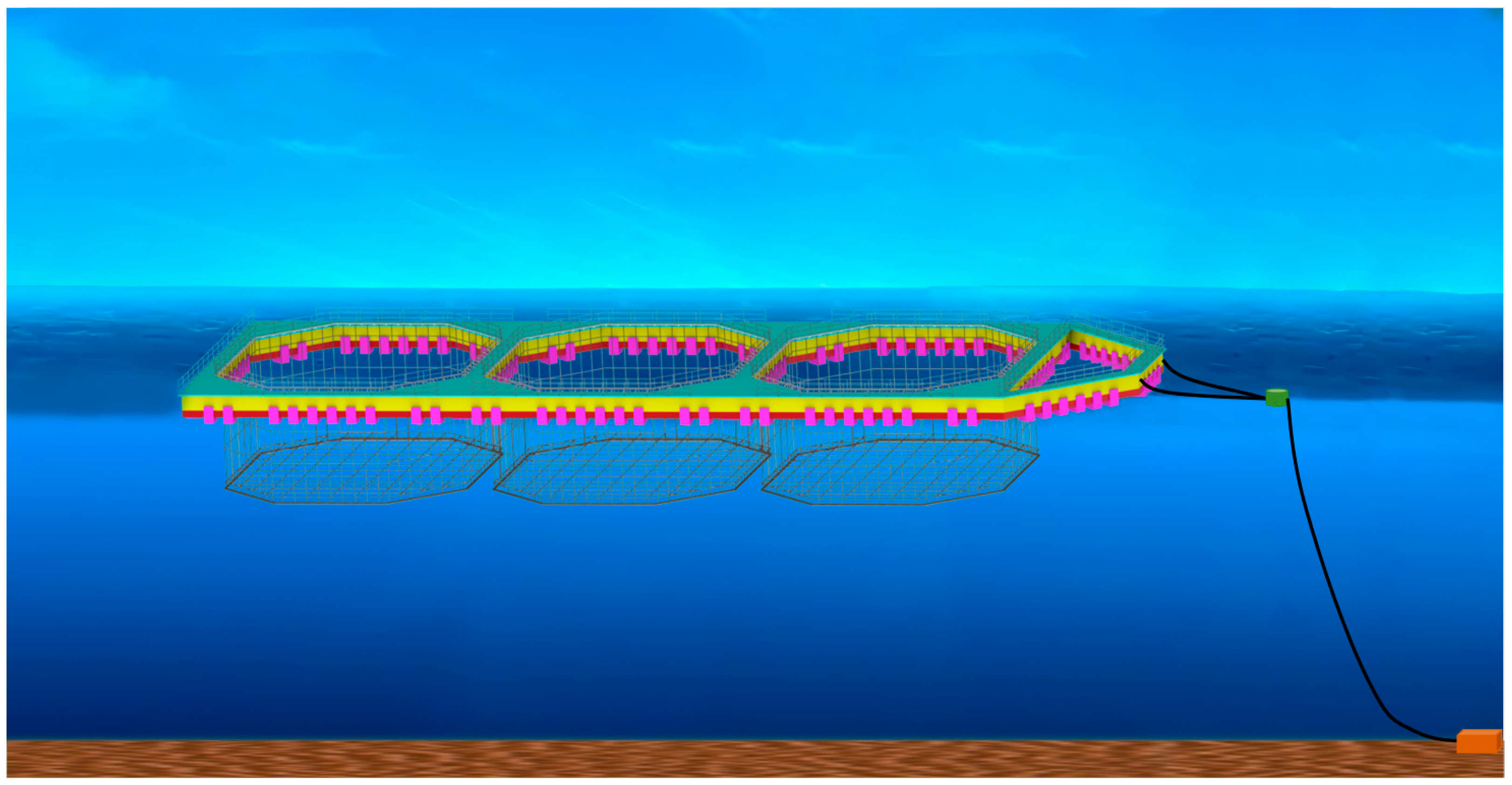
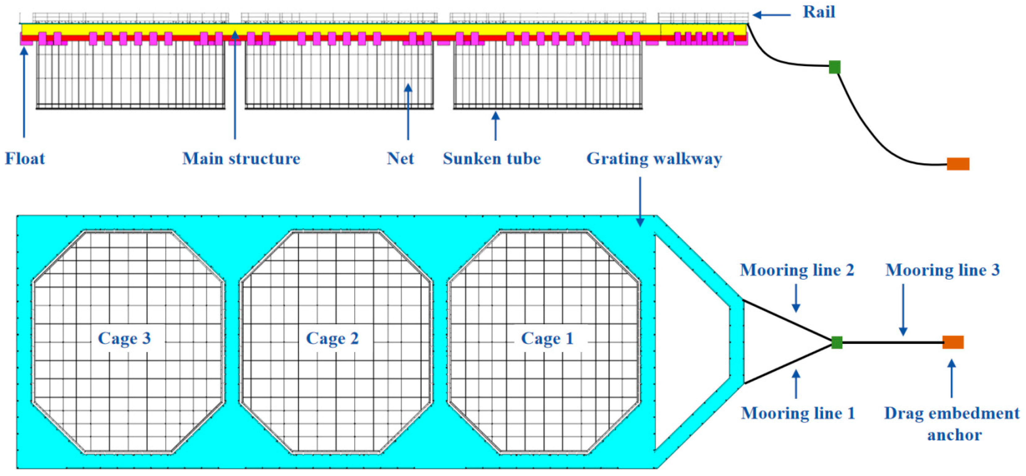
2. Proposed Conceptual Design of the Deep-Sea Aquaculture Platform

As illustrated in Figure 1, this section proposes the design of an innovative deep-sea aquaculture platform, comprising three principal components: the main structure, the netting system, and the mooring system. The main structure provides the foundational support for the platform to ensure buoyancy and structural integrity. The netting system maintains a specified aquatic space conducive to fish habitation, which prevents fish escape and effectively blocks external predators. The mooring system secures the platform within the designated aquaculture zone to prevent drift in adverse wind and wave conditions, thereby reducing economic losses.
The main structure of the aquaculture platform comprises a steel structural frame integrated with HDPE floats. The steel framework ensures structural integrity and provides essential reserve buoyancy for the platform, while the HDPE floats reduce the usage of steel materials, enhance corrosion resistance, and contribute additional buoyancy. The HDPE floats can be securely attached to the steel frame using bolts and clips. This connection method is simple and reliable, allowing for easy assembly and disassembly of the floats. In case a single float is damaged, it can be conveniently replaced, ensuring the safety of the cage during its service life. The overall configuration of the netting is designed according to the structural layout of each cage area on the platform. A single-point mooring system is employed, which employs the weathervane effect to reduce the forces acting on the cages under windy and wavy conditions. It thus mitigates the risk of structural damage and mooring failures. Such an arrangement also facilitates the dispersion of aquaculture waste over a broader marine area to reduce accumulation.
The innovative deep-sea aquaculture platform proposed in this study differs from traditional HDPE cage structures. This platform employs a steel structural frame instead of conventional floating rings and frames, overcoming their inability to withstand harsh sea conditions. Compared to traditional HDPE circular cages, the proposed platform exhibits superior wave resistance, ensuring it can support larger and heavier loads. This effectively addresses the limitations of traditional HDPE aquaculture cages in developing offshore and large-scale applications. Additionally, HDPE floats require less maintenance than steel components, enhancing the platform’s durability and reducing the need for frequent replacements, thus lowering long-term operational costs. The HDPE floats are easy to assemble, disassemble, and transport, providing flexibility to adapt to various marine environments and operational requirements. The platform can accommodate three aquaculture cages, consolidating multiple cages into a single platform to facilitate integrated, large-scale, and intelligent offshore aquaculture operations. Overall, the combination of the steel structural frame with HDPE floats enhances the platform’s wave resistance and durability, addressing the limitations of using a single material, reducing structural complexity, and saving construction costs.

3. Methodology for Conceptual Design and Structural Performance Analysis

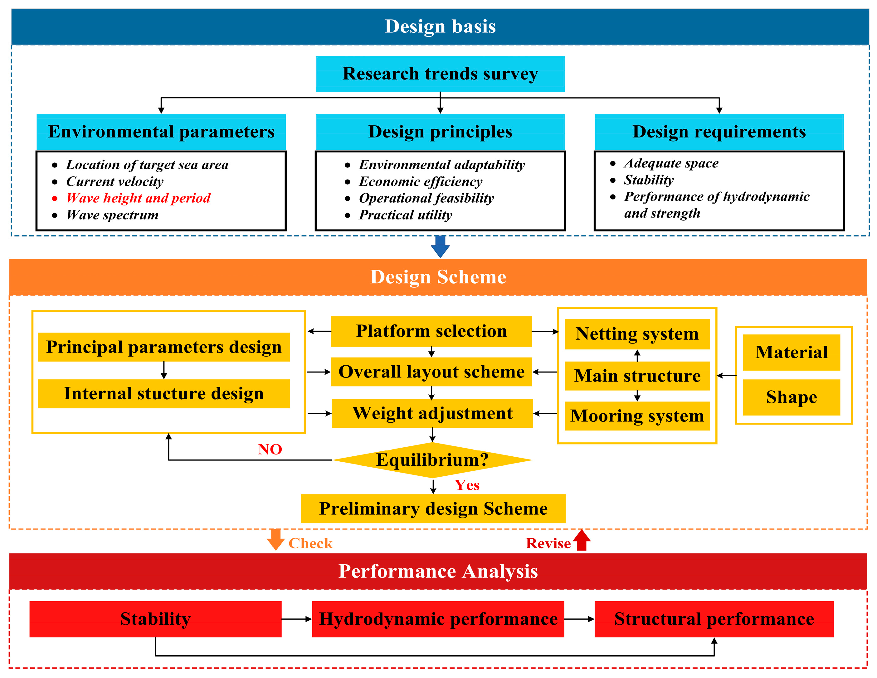
3.1. Framework and Key Process of the Methodology

Figure 2 depicts the interactive design method for the conceptual design and performance analysis of the proposed innovative deep-sea aquaculture platform. The framework and key processes are summarized as follows:
(1)
Design basis. At this stage, an extensive review was conducted to explore the current research trends in deep-sea aquaculture equipment. On this basis, the environmental parameters of the designated deployment area were determined for the innovative deep-sea aquaculture platform, including current speed, wave height, wave period, and wave spectrum. These factors were integrated with the design principles and requirements of aquaculture equipment to define essential parameters for the design and analysis of the platform.
(2)
Design scheme. At this stage, an interactive conceptual design approach was utilized to initiate the design of an innovative deep-sea aquaculture platform, covering the main structure, the mooring system, and the netting system. Orthogonal experimental methods were applied to select the optimal principal dimensions and configure the internal structure of the platform. The initial design phase set the basis for subsequent performance analyses by providing essential model parameters.
(3)
Performance analysis. Based on the conceptual design, a novel method was proposed suitable for selecting characteristic load conditions for the innovative deep-sea aquaculture platform. Based on the stochastic design wave method, design wave parameters were calculated to evaluate the platform’s strength performance, structural vulnerabilities, and overall safety under various characteristic load conditions.

3.2. Design Principles and Methods of the Platform

3.2.1. Design Principles

To ensure the rationality and practicality of the design, the conceptual approach adheres to principles such as adaptability to marine environments, ample aquaculture space, cost-effectiveness, operability, and practicality. The design of the innovative deep-sea aquaculture platform adheres to the Guidelines for Offshore Fishery Aquaculture Facilities [28] by the China Classification Society (CCS). The guidelines dictate the design loads, structural design, strength verification, stability analysis, and design requirements for mooring systems specific to marine aquaculture equipment. These standards serve as a robust framework, providing critical references and foundations for the design and performance analysis of the innovative deep-sea aquaculture platform in this study.

3.2.2. Conceptual Design Method

The novel design conception of the innovative deep-sea aquaculture platform combines a combination of a steel structural frame with HDPE floats. In this design, floats are evenly distributed around the steel framework to facilitate easy replacement of any damaged units, which replaces traditional floating frames used in aquaculture cages. As depicted in Figure 2, an interactive design process has been developed, which draws on the design principles of both domestic and international floating marine structures and incorporates the unique structural characteristics of the innovative aquaculture platform.
This process includes a comparative evaluation of existing aquaculture platforms to guide the selection and dimensional scaling based on specific design requirements. Meanwhile, it formulates the designs for the net and mooring systems of the platform. In addition, it takes into account the safety of aquaculture personnel during routine operations. Such a process produces a preliminary overall parameter configuration of the platform. Following the initial setup, the weight and center of gravity of the platform are iteratively adjusted to satisfy stability requirements. The hydrodynamic and structural performance are analyzed based on the marine environmental conditions at the location of the platform. Should these analyses reveal deficiencies that fail to meet performance standards, the principal dimensional parameters are subsequently modified until compliance with the design specifications is achieved.

3.2.3. Optimization Method for the Platform Principal Scales

The selection of principal dimensional parameters for the innovative aquaculture platform adheres to the essential principle that the net buoyancy of the platform must balance its weight and the vertical loads from the mooring system. The selection process of the principal dimensions of the platform requires a comprehensive evaluation of their impact on the choice of internal structures, the overall layout, and the buoyancy state of the platform. Moreover, it is essential to evaluate the effects of the principal dimensional parameters of the main structure on hydrodynamic performance and construction costs. Figure 3 depicts the design workflow for the principal dimensions of the main structure of the proposed deep-sea aquaculture platform.
Based on relevant data from the main structure, netting system, and mooring system, the required net buoyancy for the platform is calculated and determined to achieve positive buoyancy and the available displacement volume. After the initial principal dimensions are determined, these must satisfy the spatial requirements for the netting, upper walkways, and net buoyancy. Subsequently, the static buoyancy of the platform is assessed to ensure compliance with established criteria. If the requirements are met, further development will be based on these dimensions. Otherwise, it is necessary to reassess and reselect the principal dimensions.
Based on the initial selection of principal dimensions of the platform, orthogonal experimentation is used to analyze the hydrodynamic performance and cost coefficient of the main structure, aiming to identify the most advantageous principal dimensional parameters. The cost coefficient is a critical metric for assessing the economic efficiency of the platform. To evaluate the optimal principal dimensional scheme for the aquaculture platform, the platform cost coefficient, denoted as α, is defined as follows:
α = c s
where α is the cost coefficient, c is the perimeter of the platform frame, and s is the area enclosed by the platform frame.
The proposed innovative aquaculture platform combines a steel structural frame and HDPE floats. The selection range for the optimal principal dimensions is strategically set to fall between the characteristics of steel structure vessel-shaped aquaculture platforms and HDPE vessel-shaped aquaculture cages. The preliminary dimensions of the platform may include a length ranging from 65 m to 85 m and a width ranging from 21 m to 25 m. Following the principles of orthogonal design, three levels are selected for the length, width, and bow width of the platform, which intentionally disregards the interactions between factors. Table 1 details the choices for these factors and levels.

3.3. Environmental Design Criteria

The proposed innovative deep-sea aquaculture platform will be deployed in the Yellow Sea and Bohai Sea regions. Due to its single-point mooring system, the platform exhibits a weathervane effect under wave action. Considering the sea conditions of the Yellow Sea and Bohai Sea areas, a wave height of 5 m, a wave period of 4.5 s, and a wave direction of 180 degrees [29] have been selected for the simulation wave conditions in the principal dimensional optimization study of the platform.
The short-term forecasting of characteristic loads requires integration with wave spectra. The Jonswap spectrum and the Pierson–Moskowitz (P–M) spectrum are commonly utilized in engineering. The P–M spectrum, derived from empirical data collected in the North Atlantic, represents a theoretical model for describing fully developed sea waves. It is typically employed for waves generated by prolonged constant wind speeds in open ocean conditions. This spectral model is predicated on observations of oceanic wind wave data, assuming the waves have reached an equilibrium state with the wind speed. The density function of the P–M spectrum is expressed in Equation (2). This is a two-parameter spectrum, where the spectral shape is determined by the significant wave height (HS) and the peak period (TP).
S P M = 5 16 H S 2 ω P 2 ω 5 e x p [ 5 4 ( ω ω P 4 ) 4 ]
ω P = 2 π T P
where ω is the angular frequency of the waves, HS is the significant wave height, and TP is the peak period of the spectrum.
The Jonswap spectrum, derived from wave data measured in the North Sea, is utilized to provide a more precise characterization of the growth properties of wind-generated waves in actual marine environments. Unlike the P–M spectrum, the Jonswap spectrum introduces a peak at a specific frequency to illustrate the concentration of energy typical of waves generated by brief intense winds. Empirical evidence indicates that the Jonswap spectrum closely aligns with observed results and applies to wind waves at various developmental stages. Hence, the Jonswap spectrum is widely adopted. The density function of the Jonswap spectrum is outlined in Equation (4). This three-parameter spectrum is shaped by HS, TP, and γ, where γ essentially quantifies the concentration of wave energy. For identical HS and TP values, an increased γ leads to a greater concentration of energy around TP, resulting in a more pronounced spectral peak.
S J O N ω = A S P M ω γ e x p [ 0.5 ( ω ω P σ ω P ) 2 ]
A = 1 0.287 l n ( γ )
where γ is the peak enhancement factor, averaging 3.3, σ is the spectral shape parameter, set to 0.09 when the wave frequency ω exceeds ωp, and 0.07 otherwise, and A is a dimensionless parameter.
The relationship between the zero-crossing period (TZ) and the peak period (TP) is shown in Equation (6).
T Z T P = 0.6637 + 0.05037 γ 0.00623 γ 2 + 0.0003341 γ 3
The Jonswap spectrum is selected for calculating the characteristic load responses of the platform, with a peak enhancement factor set at 3.3. A short-term simulation duration of three hours is selected to forecast the characteristic load response under various operational conditions.
Following the Guidelines for Offshore Fishery Aquaculture Facilities [28] by the CCS, the design loads for the aquaculture platform include wind loads, current loads, wave loads, gravity loads, net loads, and other functional loads. The platform is designed to withstand a 50-year wave recurrence period. During the calculation of environmental loads, the effects of sea currents and wind loads can be temporarily excluded to solely focus on the impact of wave loads. The proposed innovative deep-sea aquaculture platform is typical of a large offshore floating structure. Its wave loads will be calculated using potential flow theory. Utilizing wave parameters derived from the stochastic design wave method, the AQWA-WAVE 18.0 software calculates the wave load files for different design wave scenarios, which facilitates the transfer of wave loads to the structural finite element model.

3.4. Wave Load Calculation Methods

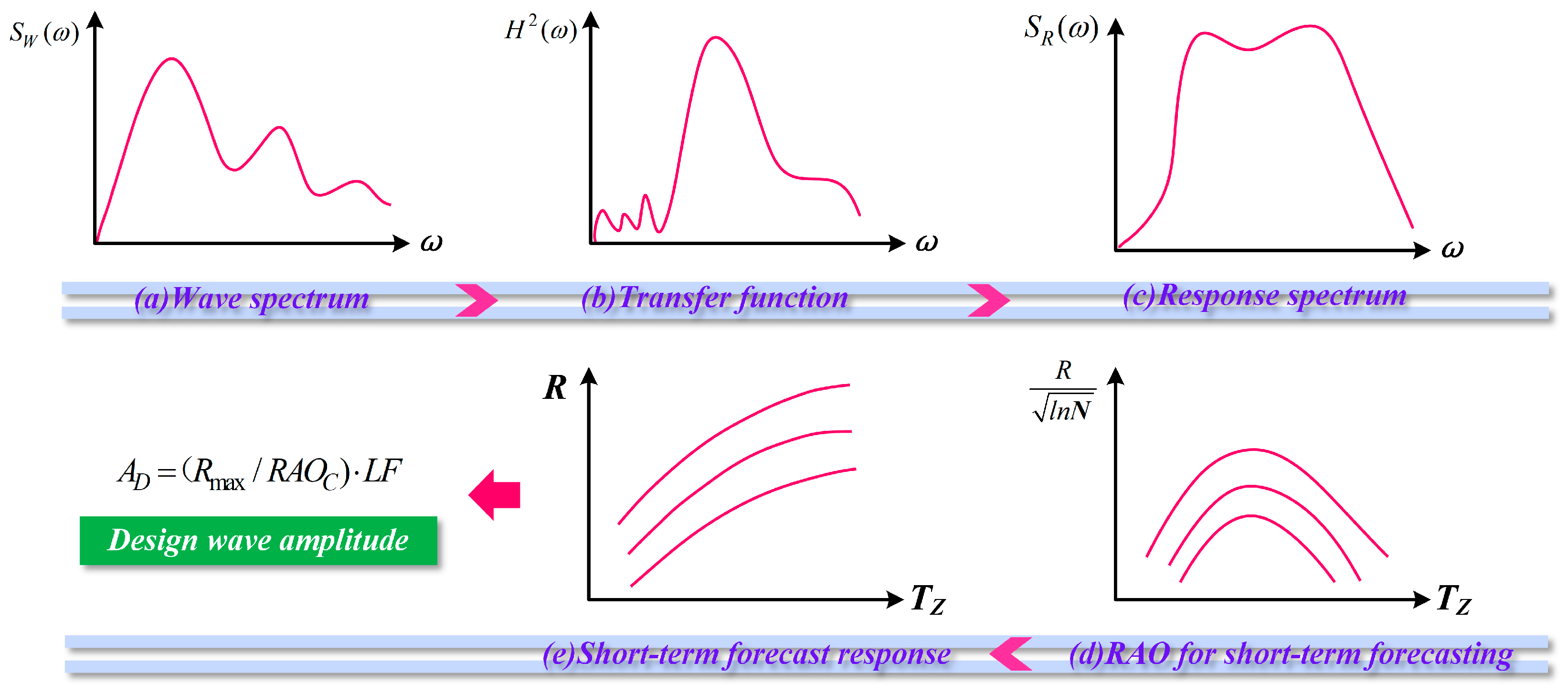
3.4.1. Stochastic Design Wave Method

The stochastic design wave method integrates short-term sea wave spectra within a specified timeframe to predict wave loads. It can effectively account for the irregularity and randomness of the waves and thereby provide a more accurate reflection of actual marine conditions. A fundamental distinction between the stochastic design wave method and the deterministic design wave method lies in their differing approaches to determining wave height. The stochastic method offers higher computational accuracy and produces results that are more scientifically robust compared to the deterministic approach. Figure 4 outlines the process of determining design parameters using the stochastic design wave method. It involves the following specific steps:
(1)
Based on the structural characteristics and the specific maritime region of the structure, select suitable wave directions, periods (frequencies), and increments to calculate the Response Amplitude Operator (RAO) function, RAO(ω).
(2)
Select the wave direction and period (frequency) corresponding to the maximum value on the characteristic load response curve to serve as the direction and period (frequency) of the design wave. Determine the wave phase through phase-frequency analysis.
(3)
Define a zero-crossing period interval for irregular waves between 3 and 18 s, with a step size of 0.1 s, and calculate the significant wave height using the wave steepness formula for irregular waves within this interval [30], as presented in Equation (8) as follows:
S S = 2 π H S g T Z 2
s s =     1 10                                                                                     T Z < 6   s 1 15                                                                                         T Z > 12   s l i n e a r   i n t e r p o l a t i o n                             6   s < T Z < 12   s
where HS is the significant wave height of irregular waves, TZ is the zero-crossing period of irregular waves, SS is the wave steepness of irregular waves, and g is the gravitational acceleration.
(4)
Select an appropriate wave spectrum and compute the wave spectrum density function, SW(ω), for each short-term sea condition.
(5)
Multiply the square of the RAO(ω) amplitude by the wave spectrum density function, SW(ω), to derive the characteristic load response spectrum, SR(ω), for each short-term sea condition.
(6)
Forecast the maximum response value, Rmax, of the characteristic loads under each short-term sea condition using the characteristic load response spectrum, SR(ω).
R m a x = m n 2 l n N
m n = 0 ω n S R ( ω ) d ω
N = D / T a
T a = 2 π m n / m 2
where mn is the nth-order moment of the response spectrum. Specifically, m0 represents the total wave energy, quantified as the variance across either unit area or the process, m2 is the variance of the first derivative of wave elevation, while m4 pertains to the variance of the second derivative of wave elevation, indicative of the acceleration variance of the wave profile. N is the number of cycles, Ta is the average zero-crossing period of the response, and D is the duration, which is typically assumed to be 3 h for short-term sea conditions.
(7)
Calculate the wave amplitude, AD, of the stochastic design wave method using Equation (13), where the design wave height is twice the wave amplitude.
A D = ( R m a x / R A O C ) · L F
where LF is the load factor, which is generally taken to be between 1.1 and 1.3.

3.4.2. Wave Load Conditions Selection Method

In the selection process of selecting design wave parameters through the design wave method, the primary step involves choosing appropriate characteristic load response conditions. The current DNV and ABS [30,31] standards specify several typical characteristic load conditions for semi-submersible platforms. However, the structural form of the proposed deep-sea aquaculture platform in this study deviates from traditional semi-submersible platform structures. It thus renders the use of standard semi-submersible platform characteristic load conditions unsuitable for selecting design wave parameters. Consequently, this paper introduces a novel approach to sectional load control, divergent from other floating structures, to comprehensively assess the impact of various wave load conditions on the structural performance of the platform.
The platform is sectioned along the y-axis and x-axis, as illustrated in Figure 5. Given the large open slender body structure of the platform, it is likely to experience significant vertical shear forces, vertical bending moments, and torsion under wave action. These loads serve as the basis for selecting characteristic load conditions. The response values of characteristic loads at various transverse and longitudinal sectional positions are calculated to identify the maximum characteristic load and its location to establish the characteristic load response condition. It thus enables an accurate assessment of the structural strength of the platform. This method effectively resolves the issues associated with the poor universality and low accuracy of traditional characteristic load selection methods for new structures, which offers a reference framework for selecting wave load conditions for innovative structural forms.

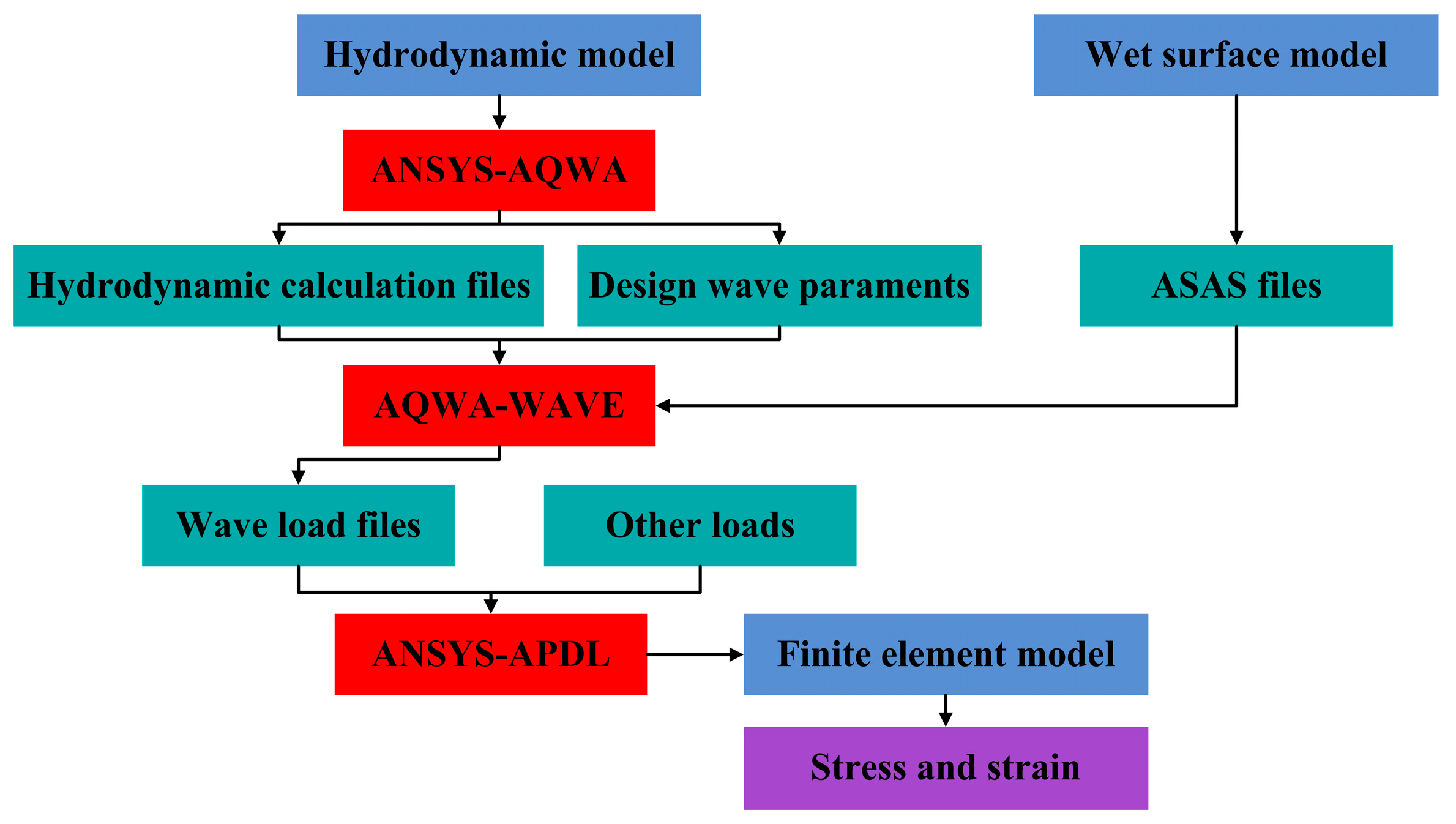
3.5. Structural Strength Analysis Method

Based on the guidelines specified in the Rules for the Classification of Mobile Offshore Units [32] by the CCS, the structural yield strength verification is conducted by the stipulations of Equations (14) and (15). The procedure for verifying structural strength is depicted in Figure 6.
σ e q = σ x 2 + σ y 2 σ x σ y + 3 τ x y 2
σ e q [ σ ] = σ s S
where σeq is the equivalent stress, σx is the stress in the x-direction of the element, σy is the stress in the y-direction of the element, τxy is the shear stress within the plane of the element in the xy-direction, σs is the yield strength of the material, and S is the safety coefficient of the material, which should be selected as presented in Table 2.

4. Case Study

4.1. Design Scheme of the Deep-Sea Aquaculture Platform

According to the design method and principle of Section 3, the designed schematic of the innovative deep-sea aquaculture platform is illustrated in Figure 7. The primary structure consists of a steel framework integrated with HDPE floats. The design accommodates three aquaculture cages arranged sequentially on the platform, with adjacent cages sharing a steel cross-brace to enhance structural integrity. Diagonal braces within each cage serve to consolidate multiple cages on a single platform, facilitating integrated, large-scale, and automated deep-sea aquaculture operations. The platform also features an upper grating walkway to facilitate routine operations by aquaculture personnel and to allow the installation of supplementary equipment, such as lifting gear. Safety rails are installed on both sides of the walkway to ensure the safety of personnel during operations.
The net cages are designed to conform to the structural framework of each area on the platform, generally adopting a cubic form with an octagonal plan view. Modular connectors inside each cage area enable easy and flexible installation and removal of the netting. It ensures that net installation is both straightforward and reliable across various sections of the platform.
A catenary single-point mooring system is utilized to significantly reduce the forces exerted by wind and waves on the platform. In regions with strong waves and wind, this mooring method provides substantial buffering, thereby reducing the risk of structural damage. The design includes two mooring chains installed on both sides of the bow of the platform, which are designated as mooring line 1 and mooring line 2. These chains connect to the upper end of mooring line 3, whose lower end is anchored securely to the seabed with a drag embedment anchor (DEA) to ensure robust stability under adverse conditions.
The structural framework of the proposed innovatively designed aquaculture platform employs Q345 steel. The buoyancy blocks are uniformly arranged atop the framework, which is fabricated from HDPE. The relevant material parameters are detailed in Table 3. Moreover, the preliminary specifications for the anchor chains in the mooring system are provided in Table 4.
Based on the overarching conceptual design of the innovative deep-sea aquaculture platform, the internal components were designed employing normative design principles, as outlined in the Rules for the Classification of Mobile Offshore Units [32] by the CCS. Figure 8 illustrates the schematic of the internal structure of the platform, which incorporates critical structural elements such as bulkhead, floor, longitudinal, and girder. This design ensures that the main framework of the aquaculture platform possesses adequate structural strength to withstand various operational demands.
Based on the conceptual design and the comprehensive layout scheme, the principal parameters of the innovative deep-sea aquaculture platform are detailed in Table 5. These parameters provide a robust data foundation for subsequent sections of the study.

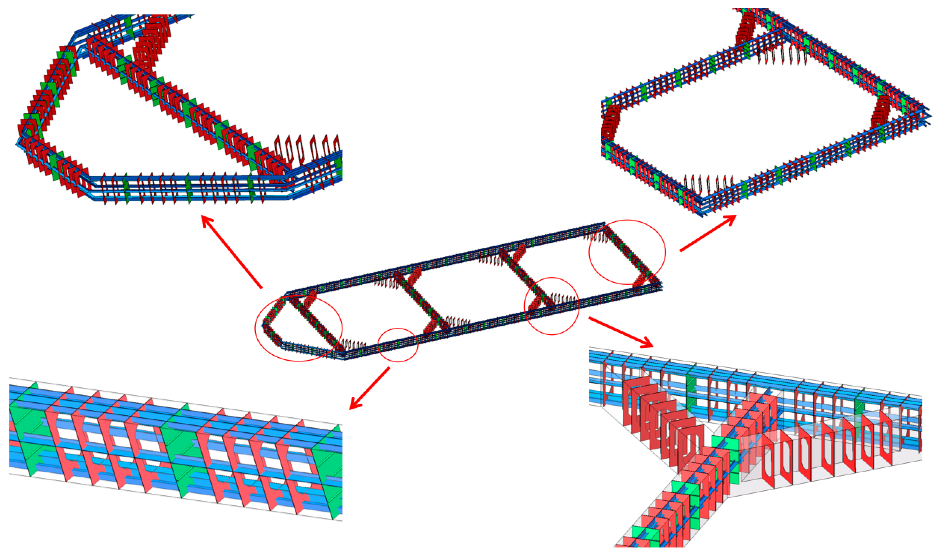
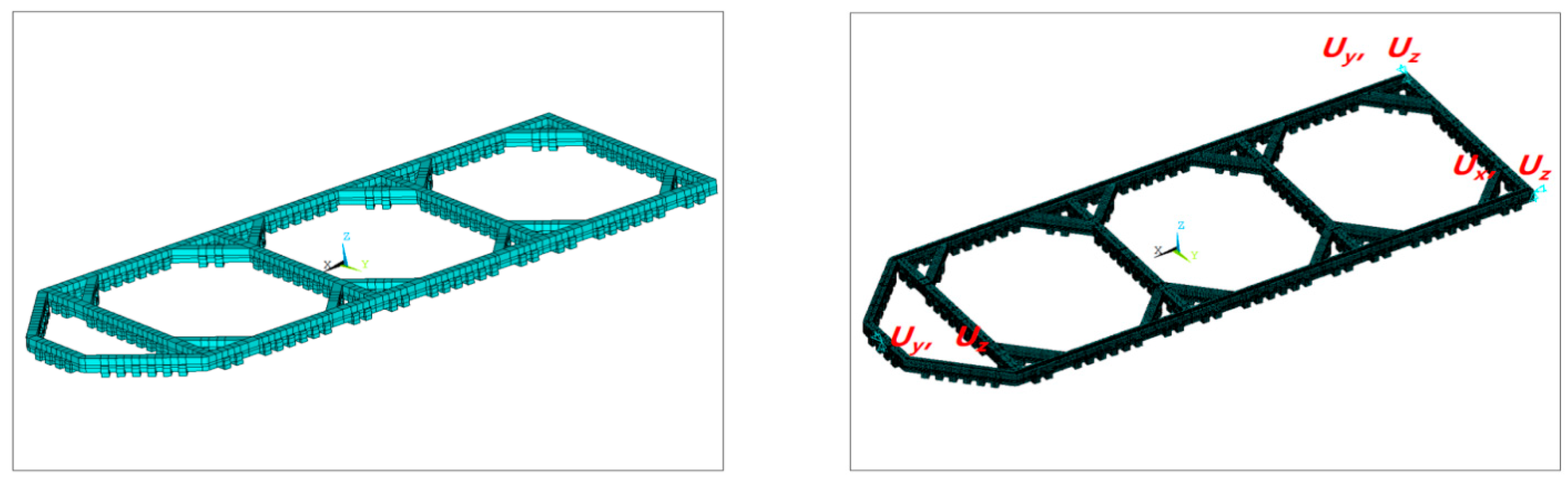
4.2. Numerical Model of the Deep-Sea Aquaculture Platform

In this section, the hydrodynamic and structural finite element models of the innovative aquaculture platform are established using the ANSYS 18.0 software. When establishing the hydrodynamic model utilizing ANSYS-AQWA 18.0, the wave direction analysis can be restricted to the range between 0 degrees and 180 degrees due to the symmetry of the platform. In addition, the wave direction along the positive x-axis is designated as 0 degrees, while the direction along the positive y-axis is set at 90 degrees. In the calculation and analysis of characteristic load responses for the platform under various operational conditions, an initial wave direction increment of 15 degrees is employed. The frequency range for regular waves is defined from 0.2 rad/s to 2.1 rad/s, with wave frequencies spaced at intervals of 0.5 rad/s between 0.4 rad/s and 1.2 rad/s, and at 1 rad/s intervals within other frequency ranges.
Regarding the hydrodynamic model based on the conceptual design, only the external structure of the platform needs to be modeled. The internal structures such as bulkheads and floors can be omitted. The final mesh of the platform’s hydrodynamic model features a maximum cell size of 0.3 m, comprising 37,184 nodes and 37,242 elements.
According to the design scheme, a finite element model of the innovative aquaculture platform is established. Unlike the hydrodynamic model, the finite element model of the platform structure includes the hull model and the complete internal structural model. When modeling the overall structure of the platform, minor structures such as mooring hooks, grating walkways, and railings were excluded. The main structural frame, bulkhead, floor, girder, and longitudinal were modeled using shell elements (SHELL 181), while the fill material inside the floats was represented with solid elements (SOLID 185). The finite element geometric model of the platform is depicted in Figure 9a.
The proposed aquaculture platform, designed with a vessel-shaped structure, required careful selection of boundary conditions to avoid impacting strength calculations. According to Section 8.2.3.4 of the Rules for the Classification of Floating Offshore Installations by the CCS [33], a three-point constraint system was utilized. It includes constraining displacement in the y and z directions at a structurally robust node at the bow and the stern. The nodes at the intersections with the side shells are selected to constrain displacement in the x and z directions, and in the y and z directions, respectively, as illustrated in Figure 9b.

5. Results Analysis

5.1. Optimization Results of the Principal Scale Parameters

The orthogonal experimental method is employed to analyze three principal dimensional factors of the platform: length, width, and bow width. A three-factor, three-level orthogonal design is implemented. The findings concerning the main structural heave amplitude, pitch angle, and cost coefficient of the platform are presented in Table 6.
Table 6 details the results based on the range analysis method. Figure 10a–c depict the variations in heave amplitude, pitch angle, and cost coefficient in response to changes in the experimental factors.
As depicted in Figure 10a, the length of the aquaculture platform significantly influences the heave amplitude. That is, the heave amplitude decreases as the platform length increases. The platform width and the bow width affect the heave amplitude similarly. As is seen, the trend of the curves initially decreases and then increases, albeit with relatively minor variations. Generally, longer structures exhibit lower natural frequencies. This significantly impacts the heave amplitude of the aquaculture platform. In contrast, increasing the width has a lesser effect on the natural frequency, thereby having a smaller impact on the heave amplitude. From a heave amplitude perspective, the optimal combination is identified as A2B3C2, i.e., a bow width of 7 m, a length of 81 m, and a width of 23 m.
The pitch angle serves as a crucial metric for assessing the performance of aquaculture platforms. Large pitch angles can potentially lead to platform capsizing and induce movements in the net cages, which consequently compress the cultivated water space and endanger the fish. As illustrated in Figure 10b, changes in the length of the platform substantially affect the pitch angle, displaying a trend of initially decreasing and then increasing. The pitch angles at lengths of 69 m and 81 m are nearly identical. This is primarily because an increase in length significantly raises the platform’s moment of inertia. Although the restoring moment coefficient also increases, it is insufficient to counteract the increased moment of inertia, ultimately reducing the platform’s natural roll frequency and affecting the pitch angle. When the platform width or bow width increases, the pitch angle into account, the optimal configuration is A3B2C3, i.e., a bow width of 8 m, a length of 75 m, and a width of 25 m.
As Figure 10c reveals, the cost coefficient of the aquaculture platform decreases while platform frame length, width, and bow width increase. The most significant reduction is observed when the frame width increases. This is because increasing the same length and width does not change the platform’s perimeter, while increasing the width encloses a larger area than increasing the length, resulting in a more significant change in the cost coefficient. From a cost-efficiency standpoint, the optimal combination is A3B3C3, i.e., a bow width of 8 m, a length of 81 m, and a width of 25 m.
The analysis indicates that the influence of factors on heave follows the order B > C > A. The influence on the pitch shows the same pattern. The relative influences on the cost coefficient follow the sequence C > B > A, differing from their effects on heave and pitch. Consequently, a new index termed comprehensive coefficient E is introduced, which is calculated as the product of the pitch and cost coefficient of the platform frame. As shown in Figure 10d, the trend of the comprehensive coefficient with the trend of the influence on pitch. A comprehensive analysis of the trade-off between performance and construction costs of the aquaculture platform indicates that the optimal configuration, according to the comprehensive coefficient, is A3B2C3, i.e., a bow width of 8 m, a length of 75 m, and a width of 25 m.

5.2. Structural Performance Analysis under the Characteristic Load Conditions

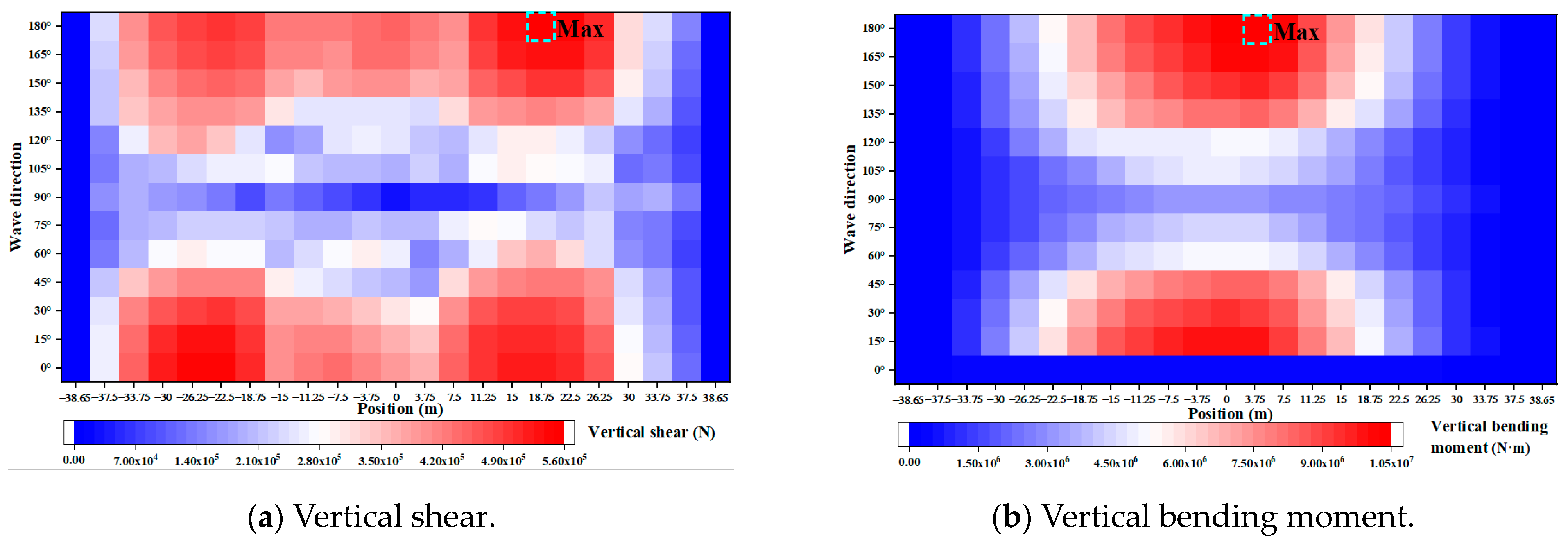
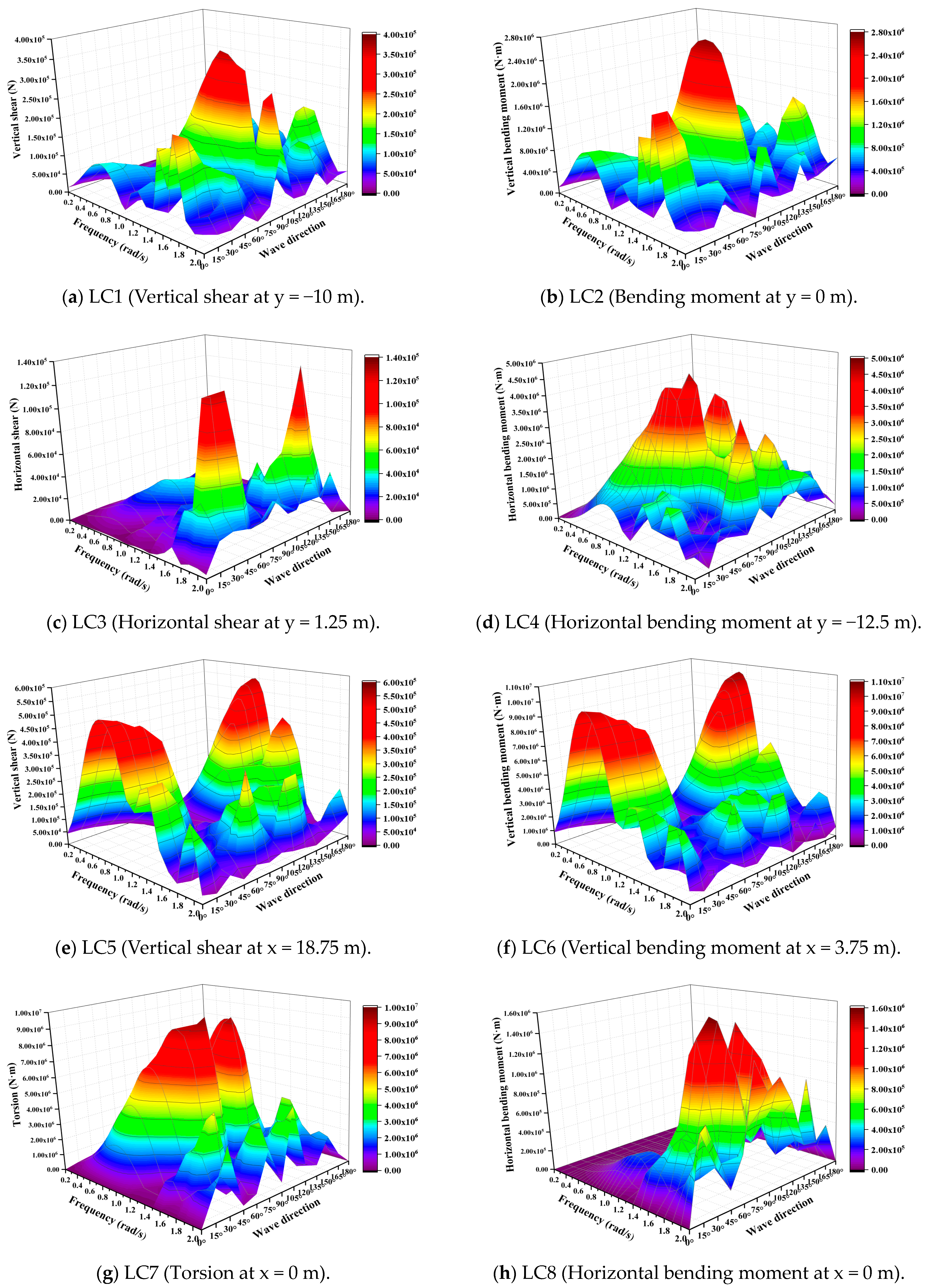
5.2.1. Selection of the Characteristic Load Conditions

Figure 11 and Figure 12 present the load distribution results at the sectioned positions along the y-axis and x-axis under various loads, as analyzed using AQWA.
From Figure 11, the maximum vertical shear response appears at the section at y = −10 m, with a corresponding wave direction of 90 degrees (beam waves). The maximum vertical bending moment is observed at the section at y = 0 m, also with a wave direction of 90 degrees (beam waves). The maximum horizontal shear response occurs at y = 1.25 m, with the wave direction of 135 degrees (oblique waves). The maximum horizontal bending moment is observed at y = −12.5 m, with the wave direction of 75 degrees (oblique waves).
From Figure 12, the maximum vertical shear response is located at x = 18.75 m, with the wave direction of 180 degrees (head waves). The maximum vertical bending moment occurs at x = 3.75 m, with the wave direction also of 180 degrees (head waves), the highest torsion is observed at x = 0 m, with the wave direction at 75 degrees (oblique waves). The maximum horizontal bending moment is at x = 0 m, with the wave direction of 75 degrees (oblique waves). The above eight types of sectional loads are designated as characteristic loads, with the corresponding response conditions detailed in Table 7.
In head wave conditions, while the platform’s mass distribution remains constant, the buoyancy along the direction of wave propagation undergoes significant changes. The variation in buoyancy relative to the static water condition generates vertical shear forces and bending moments. Specifically, the dynamic pressure of the waves distributes unevenly on the bottom and sides of the platform, causing significant vertical shear forces along its length. Additionally, the differential hydrodynamic pressure between the bottom and top of the platform alters the shear force. This pressure difference, varying with wave amplitude and frequency, leads to dynamic changes in vertical shear force. As waves pass over the platform, alternating peaks and troughs cause the buoyancy to fluctuate, creating notable vertical bending moments along the platform’s length. Typically, the maximum vertical bending moment occurs within the central 0.4 times the platform length, where wave loads induce the most significant bending stress. This finding is consistent with the results shown in Figure 11 and Figure 12.
In oblique wave conditions, the wave-induced pressure distribution on the platform is usually asymmetrical, leading to differential forces at various points and generating horizontal torque. The platform tilts in oblique waves, altering the position of the center of buoyancy. The offset between the center of buoyancy and the center of gravity creates a restoring moment, attempting to return the platform to a horizontal state. However, due to continuous wave action, this moment manifests as dynamic horizontal torque. Moreover, oblique waves change the platform’s frontal area, resulting in asymmetrical hydrodynamic forces. For instance, one side may experience greater fluid impact than the other, further increasing horizontal torsion.

5.2.2. Analysis of the Design Wave Parameters

The transfer functions for each characteristic load of the innovative deep-sea aquaculture platform are calculated based on three-dimensional potential flow theory, as shown in Figure 13.
As seen in Figure 13, it is apparent that the RAO curves exhibit notable variations across different characteristic load conditions. The wave directions and frequencies corresponding to the RAO peaks under each characteristic load condition are selected as the wave direction and frequency for the design wave. The Jonswap spectrum is employed to compute parameters for each short-term sea state, integrated with the response transfer functions for each characteristic load condition. The integration facilitates the short-term forecasting of load responses. Subsequently, the height of the design wave is calculated using Equation (13). Table 8 presents the extreme values of the short-term forecasts, along with the design wave parameters under each characteristic load condition.
The stochastic design wave method leverages short-term wave spectra over a specified period to predict wave loads under short-term sea conditions, which comprehensively accounts for the irregularity and randomness of waves. This method aligns more closely with the actual environmental conditions affecting marine platforms and offers more precise, scientifically valid, and rational results compared to the deterministic design wave method.

5.2.3. Structural Strength Analysis and Calibration

To verify the quality of the finite element model’s mesh division, a parameter sensitivity analysis was conducted using six mesh models with sizes of 0.14 mm, 0.16 mm, 0.18 mm, 0.20 mm, 0.22 mm, and 0.24 mm, as shown in Figure 14. As illustrated in Figure 14, the overall stress distribution of the platform remains essentially unchanged across different mesh sizes. The maximum Von Mises stress value increases gradually as the mesh size decreases and eventually stabilizes. Considering both the number of elements and the computational results, a mesh size of 0.2 mm was selected for the finite element model of the platform to perform subsequent yield strength verification.
Static analysis of the overall aquaculture platform structure provides Von Mises stress contour maps for both the overall structure and specific components (including the main frame, bulkhead, floor, girder, longitudinal, and float shells) under various characteristic load response conditions. Specifically, the overall stress distribution and the stress distribution within internal structures under the LC6 condition (vertical bending moment at x = 3.75 m) are presented in Figure 15.
As observed in Figure 15, the overall stress distribution within the main structural frame of the platform is uniformly moderate, except for pronounced high-stress areas at the connections between the diagonal braces and the main frame. This high stress is attributed to potential local deformations at these junctions, which cause internal stress redistribution to form high-stress concentrations at the corners. Additionally, due to the influence of wave loads, these regions of junction connection may be subjected to uneven load distributions, which compound the complexity of loads at the connection corners and exacerbate stress concentrations.
For plate and shell structures, yield strength verification typically employs the Von Mises stress criterion, which mandates that the calculated Von Mises stress should not surpass the allowable stress of the material. Table 9 summarizes the Von Mises stresses across various structural sections of the proposed aquaculture platform under different load conditions.
The data in Table 9 reveal that the Von Mises stress values in conditions LC1, LC2, LC3, and LC8 are relatively low, which all remain below 100 MPa. The maximum Von Mises stress is observed in the LC6 condition (vertical bending moment at x = 3.75 m), reaching 297 MPa. In addition, the LC5 condition (vertical shear at x = 18.75 m) and the LC7 condition (torsion at x = 0 m) also exhibit relatively high Von Mises stresses, exceeding 200 MPa. Due to the requirements for aquaculture space, a substantial area is allocated within the platform for net cage installation. However, the primary frame of the platform exhibits a relatively small width and depth, resulting in high length-to-width and length-to-depth ratios. These geometric characteristics predispose the structure to significant bending and torsional deformations under wave loads. The critical wave conditions for the overall strength of the platform include scenarios that generate maximum vertical shear and bending moments in head waves as well as maximum torsion in oblique waves. These scenarios should be prioritized in the design phase to ensure structural integrity under wave actions. The outer shell of the float, constructed using HDPE material, has an allowable stress of 27 MPa. The strength of this shell under various conditions conforms to the standards, as indicated in Table 9. The main frame, bulkhead, floor, girder, and longitudinal are fabricated by Q345 steel, which possesses a yield strength of 345 MPa. A safety factor of 1.1 is adopted for the design. Figure 16 presents the results of the yield strength verification for the structure.
As illustrated in Figure 16, the Stress variations under different conditions exhibit a consistent trend across components of the platform, with the main frame enduring the highest Von Mises stress. The design scheme of the platform is characterized by the large-opening, slender, vessel-shaped main structure, which inherently leads to lower resistance to bending moment and torsion. Under extreme environmental loads, the primary longitudinal components such as the girder and longitudinal must endure considerable axial pressure, bending moments, or shear forces to maintain structural stability, leading to elevated Von Mises stress levels in these elements. The yield strength verification of the platform structure revealed that the Von Mises stresses in components such as the main frame, bulkhead, floor, girder, longitudinal, and float shell all remain below the allowable stress values as specified in the Rules for the Classification of Offshore Mobile Platforms by the CCS. Consequently, it is affirmed that the structural strength of all components of the proposed aquaculture platform adheres to regulatory standards.

6. Conclusions

This paper proposes an innovative conceptual design of a deep-sea aquaculture platform that integrates a steel structural frame and HDPE floats. The structural performance, vulnerabilities, and overall safety of the platform under various characteristic load conditions are systematically analyzed. The main conclusions are summarized as follows.
(1)
The length of the platform significantly influences the heave and pitch amplitudes, while its width prominently affects the cost coefficient. An optimal set of primary dimensions was identified, comprising a bow width of 8 m, a length of 75 m, and a width of 25 m, which balances the hydrodynamic performance and construction costs effectively.
(2)
The short-term forecasts of characteristic loads reveal that the vertical bending moment at x = 3.75 m and the torsion at x = 0 m exhibit higher response values compared to other conditions, indicating the need for targeted structural reinforcement at these locations in the design phase.
(3)
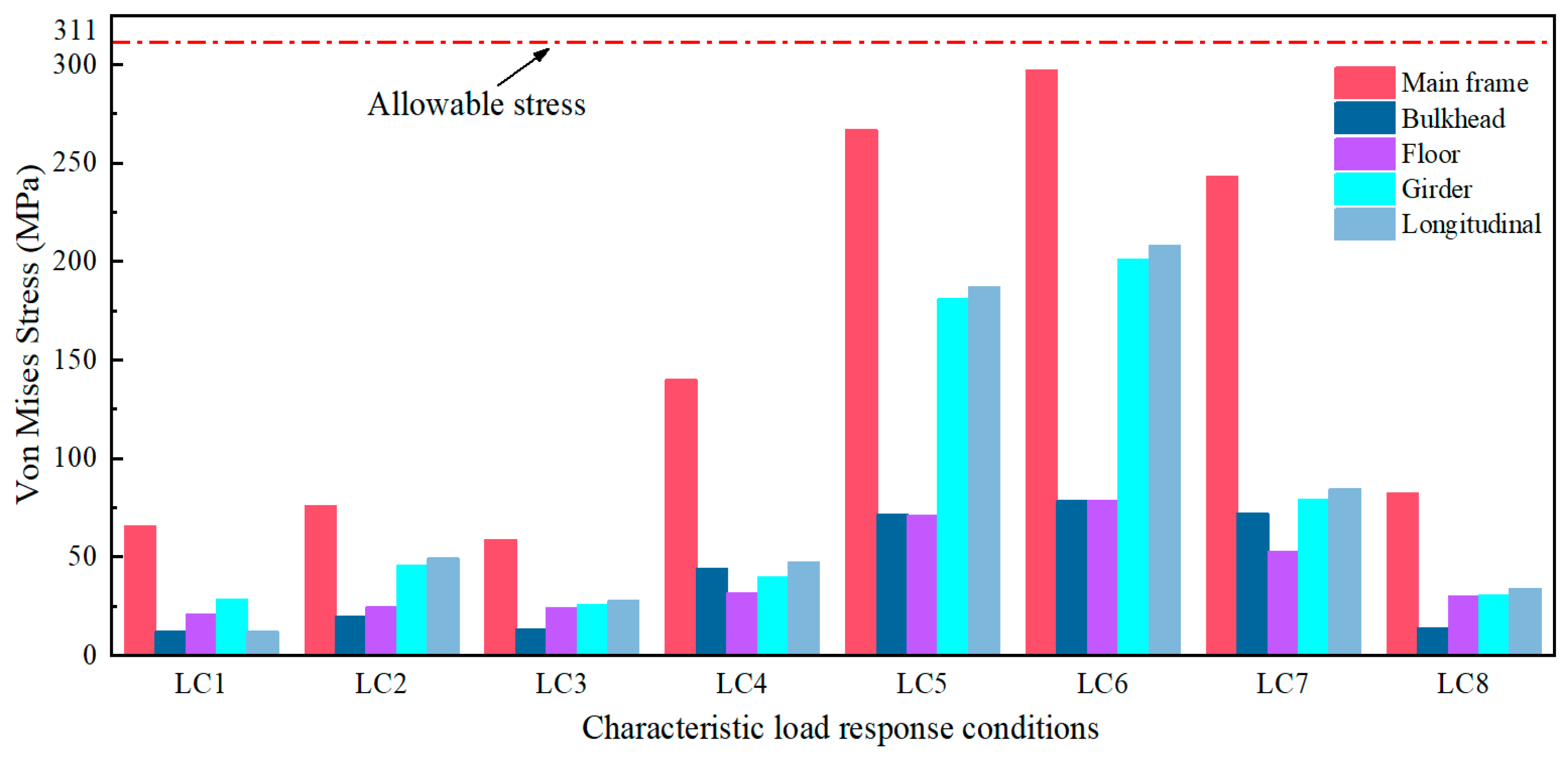
The Von Mises stresses of all sections of the platform are lower than the allowable limits of the materials used. However, stress levels were relatively higher under vertical shear, vertical bending, and horizontal torsion conditions. These scenarios require special attention in the design phase to ensure the overall structural integrity under wave action. In addition, high-stress regions are identified as the connections between diagonal braces and the main frame and where the bow diagonally connects to the first cage area, which targets fatigue life assessments.
(4)
The innovative deep-sea aquaculture platform proposed in this paper is still in the preliminary stages of design and analysis and requires further refinement. Future work should focus on the following tasks to enhance and validate the design scheme. To further improve and verify the design, it is essential to optimize the conceptual design of the novel deep-sea aquaculture platform, as well as to develop physical models and conduct experiments. Additionally, incorporating a netting system is necessary to evaluate the structural performance of the platform. Comparative analysis of the platform’s structural performance with and without the netting system should also be conducted.

Author Contributions

Conceptualization, Y.L., X.Z. and Y.Z.; methodology, Y.L., X.Z. and H.L.; software, Y.L., L.Z. and Y.Z.; validation, Y.L., X.Z. and Y.H.; formal analysis, Y.L.; Y.Z. and L.Z.; investigation, X.Z.; Y.L. and Y.Z.; resources, Y.H. and X.Z.; data curation, Y.L.; writing—original draft preparation, Y.L.; writing—review and editing, X.Z., Y.H. and H.L.; visualization, X.Z. and Y.L.; supervision, Y.H., X.Z. and H.L.; project administration, Y.H. and X.Z.; funding acquisition, X.Z. All authors have read and agreed to the published version of the manuscript.

Funding

This research is financially supported by the National Natural Science Foundation of China (No. 52171249).

Institutional Review Board Statement

Not applicable.

Informed Consent Statement

Not applicable.

Data Availability Statement

Data underpinning the findings of this study can be obtained from the corresponding author upon reasonable request.

Conflicts of Interest

Author Yesen Zhu was employed by the company PowerChina Huadong Engineering Corporation Limited. The remaining authors declare that the research was conducted in the absence of any commercial or financial relationships that could be construed as a potential conflict of interest.

References

  1. Sievers, M.; Korsoen, O.; Warren-Myers, F.; Oppedal, F.; Macaulay, G.; Folkedal, O.; Dempster, T. Submerged cage aquaculture of marine fish: A review of the biological challenges and opportunities. Rev. Aquac. 2022, 14, 106–119. [Google Scholar] [CrossRef]
  2. Chu, Y.; Wang, C.M.; Park, J.C.; Lader, P.F. Review of cage and containment tank designs for offshore fish farming. Aquaculture 2020, 519, 734928. [Google Scholar] [CrossRef]
  3. Liu, H.Y.; Pang, G.; Xiong, Y.; Yang, S.; Yuan, T.; Chen, X.; Huang, X.; Yuan, S. Material mechanics properties and critical analyses of fish farm netting and trusses. Ocean Eng. 2024, 292, 116512. [Google Scholar] [CrossRef]
  4. Gutierrez-Romero, J.E.; Lorente-Lopez, A.J.; Zamora-Parra, B. Numerical analysis of fish farm behaviour in real operational conditions. Ships Offshore Struct. 2020, 15, 737–752. [Google Scholar] [CrossRef]
  5. Kristiansen, T.; Faltinsen, O.M. Experimental and numerical study of an aquaculture net cage with floater in waves and current. J. Fluids Struct. 2015, 54, 1–26. [Google Scholar] [CrossRef]
  6. Fu, S.; Moan, T. Dynamic analyses of floating fish cage collars in waves. Aquac. Eng. 2012, 47, 7–15. [Google Scholar] [CrossRef]
  7. Lee, C.W.; Lee, J.; Park, S. Dynamic behavior and deformation analysis of the fish cage system using mass-spring model. China Ocean Eng. 2015, 29, 311–324. [Google Scholar] [CrossRef]
  8. Zhao, Y.; Bai, X.; Dong, G.; Bi, C. Deformation and stress distribution of floating collar of net cage in steady current. Ships Offshore Struct. 2019, 14, 371–383. [Google Scholar] [CrossRef]
  9. Liu, H.; Huang, X.; Pang, G.; Yuan, T.; Hu, Y.; Yuan, S. Structural mechanical properties of circular fish cages determined by finite element analysis and material test. Ocean Eng. 2022, 261, 112083. [Google Scholar] [CrossRef]
  10. Liu, H.; Huang, X.; Wang, S.; Hu, Y.; Yuan, T.; Guo, G. Evaluation of the structural strength and failure for floating collar of a single-point mooring fish cage based on finite element method. Aquac. Eng. 2019, 85, 32–48. [Google Scholar] [CrossRef]
  11. Huang, X.; Guo, G.; Tao, Q.; Hu, Y.; Liu, H.; Wang, S.; Hao, S. Dynamic deformation of the floating collar of a net cage under the combined effect of waves and current. Aquac. Eng. 2018, 83, 47–56. [Google Scholar] [CrossRef]
  12. Huang, X.; Guo, G.; Tao, Q.; Hu, Y.; Liu, H.; Wang, S.; Hao, S. Numerical simulation of deformations and forces of a floating fish cage collar in waves. Aquac. Eng. 2016, 74, 111–119. [Google Scholar] [CrossRef]
  13. Li, L.; Fu, S.; Li, R. Dynamic analysis of aquaculture fish cages in irregular waves. In Proceedings of the ASME 32nd International Conference on Ocean, Offshoreand Arctic Engineering, Nantes, France, 9–14 June 2013; Volume 3. [Google Scholar]
  14. Li, L.; Fu, S.; Xu, Y.; Wang, J.; Yang, J. Dynamic responses of floating fish cage in waves and current. Ocean Eng. 2013, 72, 297–303. [Google Scholar] [CrossRef]
  15. Li, L.; Fu, S.; Xu, Y. Nonlinear hydroelastic analysis of an aquaculture fish cage in irregular waves. Mar. Struct. 2013, 34, 56–73. [Google Scholar] [CrossRef]
  16. Xu, T.; Hou, H.; Dong, G.; Zhao, Y.; Guo, W. Structural analysis of float collar for metal fish cage in waves. Turk. J. Fish. Quat. Sci. 2017, 17, 257–268. [Google Scholar]
  17. Zhang, Y.; Guo, H.; Liu, S.; Liu, Q.; Guo, J. Fatigue vulnerability of sea cage to storm wave loads. J. Mar. Sci. Technol. 2023, 28, 153–164. [Google Scholar] [CrossRef]
  18. Sun, S.; Li, H.; Muk, C.O.; Li, L. Design load and yielding strength analyses of the floating structure of a truss-type offshore cage. J. Harbin Eng. Univ. 2022, 43, 340–347. [Google Scholar]
  19. Zitti, G.; Novelli, N.; Brocchini, M. Dynamics of a pile-moored fish cages in current and waves: A numerical study. Ocean Eng. 2023, 269, 113571. [Google Scholar] [CrossRef]
  20. Zitti, G.; Novelli, N.; Brocchini, M. Preliminary results on the dynamics of a pile-moored fish cage with elastic net in currents and waves. J. Mar. Sci. Eng. 2021, 9, 14. [Google Scholar] [CrossRef]
  21. Ma, H. Study on Structural Strength and Ftigue Analyses of Platform Net Cage. Ph.D. Thesis, Wuhan University of Technology, Wuhan, China, 2022. [Google Scholar]
  22. Zhang, J. Research on Design Load and Structural Strength Assessment Methods of Deep-Sea Floating Cage. Ph.D. Thesis, Harbin Engineering University, Harbin, China, 2023. [Google Scholar]
  23. Pang, G.; Huang, X.; Chen, C.; Yuan, T.; Hu, Y.; Wang, S.; Sun, C. Research on structural safety evaluation of jack-up offshore net cage under different conditions. Prog. Fish. Sci. 2022, 43, 56–68. [Google Scholar]
  24. Milich, M.; Drimer, N. Design and analysis of an innovative concept for submerging open-sea aquaculture system. IEEE J. Ocean. Eng. 2019, 44, 707–718. [Google Scholar] [CrossRef]
  25. Zhang, Y.C.; Zhang, J.; Jiang, C.Q.; Zhang, Z.D.; Xu, P.; Zhang, Y. Hydrodynamic and structural optimization of a truss-floating aquaculture vessel. J. Mar. Sci. Eng. 2023, 11, 2385. [Google Scholar] [CrossRef]
  26. Cao, Y.; Li, Z.; Wang, K.W.; Ye, Q. Sensitivity of dynamic response of truss-type aquaculture platform to floating body arrangement. J. Mar. Sci. Eng. 2024, 12, 431. [Google Scholar] [CrossRef]
  27. Wang, C.M.; Nguyen, H.P. Advances in research and developments on offshore aquaculture and renewable energy production. In Proceedings of the Third International Conference on Sustainable Civil Engineering and Architecture, Da Nang City, Vietnam, 19–21 July 2023; Lecture Notes in Civil Engineering. Springer: Singapore, 2024; pp. 3–22. [Google Scholar]
  28. CCS. Guidelines for Offshore Aquaculture Facilities; China Communications Press: Beijing, China, 2023. [Google Scholar]
  29. Qiao, S.; Sun, J.; Shi, H.; Sun, Q. Spatial and temporal characteristics of wave engergy resources in the yellow sea and bohai sea using era5 datasets. Oceanol. Limnol. Sin. 2020, 51, 1350–1358. [Google Scholar]
  30. DNV. Column-Stabilized Units; Det Norske Veritas: Høvik, Norway, 2012. [Google Scholar]
  31. ABS. Rules for Building and Classing Mobile Offshore Drilling Unit; American Bureau of Shipping: Houston, TX, USA, 2016. [Google Scholar]
  32. CCS. Rules for the Classification of Mobile Offshore Units; China Communications Press: Beijing, China, 2023. [Google Scholar]
  33. CCS. Rules for the Classification of Floating Offshore Installations; China Communications Press: Beijing, China, 2023. [Google Scholar]
Figure 1. Sketch of the innovative deep-sea aquaculture platform.
Jmse 12 01058 g001
Figure 2. Framework and process of the methodology of conceptual design and performance analysis.
Jmse 12 01058 g002
Figure 3. Optimization method for the principal scales of the platform.
Jmse 12 01058 g003
Figure 4. Flowchart of the stochastic design wave method.
Jmse 12 01058 g004
Figure 5. Position of platform section division.
Jmse 12 01058 g005
Figure 6. Structural strength analysis flowchart.
Jmse 12 01058 g006
Figure 7. Schematic of the platform layout scheme.
Jmse 12 01058 g007
Figure 8. Schematic of the platform internal structure of the platform.
Jmse 12 01058 g008
Figure 9. Finite element model and boundary constraint.
Jmse 12 01058 g009
Figure 10. Variation curve of each performance indicator with test factors.
Jmse 12 01058 g010
Figure 11. Distribution of characteristic loads along the y-axis.
Jmse 12 01058 g011
Figure 12. Distribution of characteristic loads along the x-axis.
Jmse 12 01058 g012aJmse 12 01058 g012b
Figure 13. Characteristic load response transfer function for each condition.
Jmse 12 01058 g013
Figure 14. Stress values and stress distribution under different mesh sizes.
Jmse 12 01058 g014
Figure 15. Stress distribution of platform under LC6 condition (vertical bending moment at x = 3.75 m).
Jmse 12 01058 g015
Figure 16. Results of yield strength calibration.
Jmse 12 01058 g016
Table 1. Orthogonal test factors and levels.
FactorsLevels
A (Bow width)/m678
B (Length)/m697581
C (Width)/m212325
Table 2. Summary of the safety coefficients.
ConditionType of StressSafety
Coefficient
ConditionType of StressSafety
Coefficient
Static load
condition
Axial and bending stress1.67Combined load
conditions
Axial and bending stress1.25
Shear stress2.50Shear stress1.88
Composite stress1.43Composite stress1.11
Table 3. Material parameters of the aquaculture platform.
MaterialParametersValueMaterialParametersValue
Q345 steelYield strength345 MPaHDPEYield strength30 MPa
Density7850 kg/m3Density953 kg/m3
Young’s
modulus
2.1 × 10⁵ MPaYoung’s
modulus
9.0 × 10² MPa
Poisson’s ratio0.3Poisson’s ratio0.38
Table 4. Material properties of mooring lines.
Number of
Mooring Line
MaterialDiameter
/mm
Dry Weight
/(kg/m)
Wet Weight
/(kg/m)
Axial Stiffness
/kN
Fracture Tension
/kN
Mooring lines 1–2Stud chain70107.393.24.95 × 1053687.9
Mooring line 3Stud chain100219.0190.21.01 × 1067056.0
Table 5. Key design parameters of the platform.
ParametersValueParametersValue
Length overall77.5 mBreadth extreme27.5 m
Length of netting22.8 mWidth of netting19.2 m
Height of netting8 mHeight of main structure2.3 m
Designed draught1.07 mScantling draught1.4 m
Length of floats2 mWidth of floats0.8 m
Height of floats1.4 mBuoyancy of floats152.144 m3
Mass of floats10.404 tTotal weight328.084 t
Center of gravity(−1.085 m, 0 m, 1.238 m)Ixx3.720 × 107 kg·m2
Iyy1.759 × 108 kg·m2Izz2.114 × 108 kg·m2
Table 6. Calculation results of platform main structure performance given different main scale parameters.
NumberA
Bow Width/m
B
Length/m
C
Width/m
Heave
/m
Pitch
Perimeter
/m
Area
/m2
Cost
Coefficient
1669210.7743.402171.2201392.7500.123
2675230.7191.620186.0401652.7500.113
3681250.6841.932200.8801934.7500.104
4769230.7411.767174.5401523.0000.115
5775250.7400.765189.4601794.0000.106
6781210.6452.672195.8001652.0000.119
7869250.7681.830178.0401652.7500.108
8875210.7270.873184.3801532.7500.120
9881230.6702.316199.2201806.7500.110
Table 7. Characteristic load conditions of the platform.
ConditionsCharacteristic LoadsConditionsCharacteristic Loads
LC1Vertical shear at y = −10 mLC5Vertical shear at x = 18.75 m
LC2Bending moment at y = 0 mLC6Vertical bending moment at x = 3.75 m
LC3Horizontal shear at y = 1.25 mLC7Torsion at x = 0 m
LC4Horizontal bending moment at y = −12.5 mLC8Horizontal bending moment at x = 0 m
Table 8. Short-term forecast extremes of characteristic loads and design wave parameters.
ConditionsWave Direction
Frequency
/(rad/s)
Forecast ExtremumsPhase
Wave Height
/m
LC1901.44.94 × 105 N150.833.485
LC2901.44.10 × 106 N·m−9.563.944
LC31351.97.11 × 104 N01.398
LC4751.34.26 × 106 N·m−69.142.366
LC51800.958.35 × 105 N−22.663.956
LC61800.91.55 × 107 N·m161.743.871
LC7751.41.18 × 107 N·m−32.933.156
LC8751.69.79 × 105 N·m105.791.605
Table 9. The structural Von Mises stress value of each part of the platform (MPa).
ConditionsCharacteristic LoadMain FrameBulkheadFloorGirderLongitudinalFloat Shell
LC1Vertical shear at
y = −10 m
65.412.220.928.412.01.10
LC2Bending moment at
y = 0 m
75.819.624.645.449.31.27
LC3Horizontal shear at
y = 1.25 m
58.813.124.225.527.70.68
LC4Horizontal bending moment at y = −12.5 m14044.331.739.947.40.88
LC5Vertical shear at
x = 18.75 m
26771.770.91811871.24
LC6Vertical bending moment at x = 3.75 m29778.478.42012081.18
LC7Torsion
at x = 0 m
24372.152.679.284.31.10
LC8Horizontal bending moment at x = 0 m82.514.029.830.434.00.70
Disclaimer/Publisher’s Note: The statements, opinions and data contained in all publications are solely those of the individual author(s) and contributor(s) and not of MDPI and/or the editor(s). MDPI and/or the editor(s) disclaim responsibility for any injury to people or property resulting from any ideas, methods, instructions or products referred to in the content.

